EP2851240A1 - System manuelle und automatische Doppel Rampe für Rollstuhlfahrer in einem Transportmittel - Google Patents
System manuelle und automatische Doppel Rampe für Rollstuhlfahrer in einem Transportmittel Download PDFInfo
- Publication number
- EP2851240A1 EP2851240A1 EP14002759.0A EP14002759A EP2851240A1 EP 2851240 A1 EP2851240 A1 EP 2851240A1 EP 14002759 A EP14002759 A EP 14002759A EP 2851240 A1 EP2851240 A1 EP 2851240A1
- Authority
- EP
- European Patent Office
- Prior art keywords
- pallet
- manual
- automatic
- ramp
- axis
- Prior art date
- Legal status (The legal status is an assumption and is not a legal conclusion. Google has not performed a legal analysis and makes no representation as to the accuracy of the status listed.)
- Withdrawn
Links
- 230000009977 dual effect Effects 0.000 title abstract description 8
- 230000000295 complement effect Effects 0.000 claims description 5
- 230000004048 modification Effects 0.000 description 4
- 238000012986 modification Methods 0.000 description 4
- 238000009434 installation Methods 0.000 description 3
- 230000000284 resting effect Effects 0.000 description 3
- 240000000966 Allium tricoccum Species 0.000 description 2
- 230000006378 damage Effects 0.000 description 2
- 238000001514 detection method Methods 0.000 description 2
- 230000000694 effects Effects 0.000 description 2
- 230000000670 limiting effect Effects 0.000 description 2
- 238000012423 maintenance Methods 0.000 description 2
- 241001080024 Telles Species 0.000 description 1
- 208000027418 Wounds and injury Diseases 0.000 description 1
- 230000006978 adaptation Effects 0.000 description 1
- 230000007547 defect Effects 0.000 description 1
- 238000006073 displacement reaction Methods 0.000 description 1
- 229930195733 hydrocarbon Natural products 0.000 description 1
- 150000002430 hydrocarbons Chemical class 0.000 description 1
- 208000014674 injury Diseases 0.000 description 1
- 230000010354 integration Effects 0.000 description 1
- 210000000056 organ Anatomy 0.000 description 1
- 230000003449 preventive effect Effects 0.000 description 1
- 230000000135 prohibitive effect Effects 0.000 description 1
- 230000002829 reductive effect Effects 0.000 description 1
- 230000035939 shock Effects 0.000 description 1
Images

Classifications
-
- B—PERFORMING OPERATIONS; TRANSPORTING
- B60—VEHICLES IN GENERAL
- B60P—VEHICLES ADAPTED FOR LOAD TRANSPORTATION OR TO TRANSPORT, TO CARRY, OR TO COMPRISE SPECIAL LOADS OR OBJECTS
- B60P1/00—Vehicles predominantly for transporting loads and modified to facilitate loading, consolidating the load, or unloading
- B60P1/43—Vehicles predominantly for transporting loads and modified to facilitate loading, consolidating the load, or unloading using a loading ramp mounted on the vehicle
- B60P1/433—Vehicles predominantly for transporting loads and modified to facilitate loading, consolidating the load, or unloading using a loading ramp mounted on the vehicle the loading floor or a part thereof being movable to form the ramp
-
- A—HUMAN NECESSITIES
- A61—MEDICAL OR VETERINARY SCIENCE; HYGIENE
- A61G—TRANSPORT, PERSONAL CONVEYANCES, OR ACCOMMODATION SPECIALLY ADAPTED FOR PATIENTS OR DISABLED PERSONS; OPERATING TABLES OR CHAIRS; CHAIRS FOR DENTISTRY; FUNERAL DEVICES
- A61G3/00—Ambulance aspects of vehicles; Vehicles with special provisions for transporting patients or disabled persons, or their personal conveyances, e.g. for facilitating access of, or for loading, wheelchairs
- A61G3/02—Loading or unloading personal conveyances; Facilitating access of patients or disabled persons to, or exit from, vehicles
- A61G3/06—Transfer using ramps, lifts or the like
- A61G3/061—Transfer using ramps, lifts or the like using ramps
-
- B—PERFORMING OPERATIONS; TRANSPORTING
- B60—VEHICLES IN GENERAL
- B60P—VEHICLES ADAPTED FOR LOAD TRANSPORTATION OR TO TRANSPORT, TO CARRY, OR TO COMPRISE SPECIAL LOADS OR OBJECTS
- B60P1/00—Vehicles predominantly for transporting loads and modified to facilitate loading, consolidating the load, or unloading
- B60P1/43—Vehicles predominantly for transporting loads and modified to facilitate loading, consolidating the load, or unloading using a loading ramp mounted on the vehicle
- B60P1/431—Vehicles predominantly for transporting loads and modified to facilitate loading, consolidating the load, or unloading using a loading ramp mounted on the vehicle the ramp being stored under the loading floor when not in use
Definitions
- the transport of people with reduced mobility, and more specifically wheelchair users, is one of the public service tasks entrusted to public transport networks.
- the chosen solution, cassette or subframe, is not the key element for the end user of the ramp. It is especially the mode of actuation of the ramp which has a great importance for the network. Indeed, the two modes of operation each have strong advantages and disadvantages.
- the manual ramp is typically made of a fixed panel secured to the frame and a movable panel articulated around a hinge which is at the threshold of the door. At rest, the mobile panel is superimposed on the fixed panel. The movable panel is pivoted about the axis of the hinge to rest its front end on the sidewalk and thereby create the inclined plane necessary for the passage of the wheelchair.
- the automatic ramps integrate a multitude of functions and components to realize them, for example motor, drive, guidance, sensors, safety, etc.
- Another solution would be to equip the means of transport with a manual ramp on one door and an automatic on another.
- the manual ramp would be used as a backup in case of failure of the automatic model. This represents an expensive solution.
- the means of transport are designed to receive a single ramp on the door closest to the wheelchair user location.
- a modification to a second door to install a second ramp could be considered but the standard corridors are not suitable for a wheelchair user to its location.
- This solution therefore has many defects from the point of view of the manufacturers of means of transport that can not install multiple ramps in a means of transport without heavy modifications.
- the problem underlying the present invention is to design a ramp access system for wheelchair users in a means of transport that can have the advantages of a manual ramp and an automatic ramp.
- an access ramp system for a wheelchair user in a means of transport, this system having a manual ramp comprising a manual pallet that can be deployed from a rest position in which it is integrated in the floor of the means of transport to a working position where the pallet extends inclined by having a first end at the floor of the means of transport while its opposite end rests on the sidewalk or the roadway, the manual pallet then forming a raceway for the ascent or descent of a wheelchair in the or of the means of transport, characterized in that it incorporates an automatic ramp comprising an automatic pallet deployed from a rest position in the automatic pallet is below the manual ramp to a working position similar to that of the manual pallet position manual or automatic pallets that can be selectively deployed in the working position.
- the technical effect of the present invention is to provide a solution that is suitable for all actors and their respective constraints, this by providing a dual ramp system consisting of a manual ramp superimposed on an automatic ramp. This system is compact enough to integrate into the standard ramp locations already provided in the conveyor floors.
- the manual ramp comprises a fixed panel at one end of which the manual pallet is articulated around a first hinge pin fixed in the frame so as to pass from a rest position in which the manual pallet is superimposed on the panel fixed to an extended working position in which the manual pallet has rotated more than 180 ° about the first axis of articulation relative to the fixed panel.
- each connecting element is articulated about the first axis of articulation with the fixed panel and the second end of each connecting element being articulated around a second axis of movable articulation with the manual pallet, the second axis of articulation being parallel to the first axis of fixed articulation, the connecting elements pivoting about 90 ° extending vertically in the position resting and substantially horizontally in the deployed working position of the manual pallet.
- the manual ramp is equipped with gripping means and / or means for detecting its setting in the rest position or in the working position and / or locking means in at least one of the two positions.
- the automatic ramp comprises a sliding carriage pushing the automatic pallet of the ramp outside the means of transport as well as rods interposed between the carriage and the automatic pallet, the rods being hinged at one end with the carriage around a first axis of automatic ramp articulation secured to the carriage and at the other end with the automatic pallet around a second axis automatic ramp articulation extending parallel to the first, the second automatic ramp articulation axis being movable with the automatic pallet.
- each link carries a hook provided with an open receiving groove disposed towards the end of the articulated link with the carriage, the hook extending in the length of the associated connecting rod being integral with it and being articulated around the second automatic ramp articulation axis integral with the automatic pallet.
- each open receiving groove under the action of the carriage, is pushed against a fixed abutment axis by partially surrounding it, the groove and the associated connecting rod then pivoting around the first hinge axis fixed relative to the carriage while the automatic pallet pivots around the second automatic ramp axis relative to the associated link.
- the fixed stop axis coincides with the first axis of fixed articulation of the manual pallet.
- the carriage comprises driving and guiding means for pushing the automatic pallet from a rest position to an extended working position.
- the system comprises a frame embedded in its interior manual and automatic ramps in the rest position.
- the frame comprises a vertical branch being intended to form the innermost part of the frame in the transport means and the horizontal branch forming the base of the frame in the transport means on which are mounted the manual and automatic ramps.
- the so-called opposite end of the manual pallet intended to rest on the sidewalk or the roadway in its deployed position is opposite the vertical branch of the chassis, the surfaces facing the manual pallet and the vertical leg comprising complementary shapes leaving a space between them just enough for these surfaces do not rub against each other.
- the facing surface carried by the vertical leg of the frame is beveled forming a slope in extension of the manual pallet deployed for the passage of the chair.
- the invention relates to a transport means characterized in that it comprises such an access ramp system.
- the access ramp system is embedded in a housing provided in the floor of the transport means, the upper face of the system being in the extension of the floor of the transport means in the rest position.
- the dual ramp system for access of a wheelchair user in a means of transport comprises a frame 1 which is fixed inside the floor transport means, this means of transport can be advantageously but not limited to a means of road transport, including a bus or a bus.
- the dual ramp system of the present invention integrates both the manual ramp and automatic ramp functions, as will be detailed hereinafter.
- the manual and automatic ramps are selectively put in deployed working position according to the choice of the authorized personnel, namely the most frequently the driver of the means of transport.
- the system comprises a first pallet 4, hereinafter called manual pallet, which can be deployed manually. It also includes a second pallet 8, hereinafter called automatic pallet, which can be deployed automatically.
- Each pallet 4, 8 is a flat surface that can be inclined in the deployed position between the sidewalk or the roadway on the one hand and the floor of the means of transport on the other hand.
- first manual pallet 4 or second automatic pallet 8 that can roll the wheelchair of the user, the manual pallet 4 or automatic 8 being selectively put in the deployed position.
- the manual pallet 4 or automatic 8 In this deployed position, the manual pallet 4 or automatic 8 is arranged in an inclined manner by connecting the sidewalk or the pavement on which it then rests at one end, the other of its ends being at the floor of the means of transport.
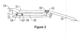
- the two deployment positions of the manual pallet 4 or automatic 8 are respectively shown to figures 2 and 3 .
- the frame 1 of the system occupies a substantially parallelepipedal volume in the means of transport.
- This frame 1 may comprise a substantially horizontal branch and a substantially vertical branch.
- the vertical branch is intended to form the innermost part of the chassis 1 in the means of transport and the horizontal branch forms the base of the frame 1 on which are mounted the manual and automatic ramps.
- This volume corresponds, with a near functional game, to that classically reserved in a means of transport for the integration of a standard access ramp for wheelchair user or UFR.
- the system according to the present invention can replace a standard access ramp without requiring specific adaptation.
- the manual ramp with its manual pallet 4 is disposed above the automatic ramp provided with its automatic pallet 8.
- the double ramp system provides for forming the manual ramp to associate with the manual pallet 4 a first panel 2 fixed and rigid.
- the first fixed and rigid panel 2 is secured to one of its longitudinal edges to the frame 1 while on its other longitudinal edge is pivotally articulated the manual pallet 4, this directly or indirectly, in this last case by elements of link 3.
- the longitudinal edge on which is articulated the manual pallet 4 comprises a first axis of articulation 10 parallel to the axis of the transport means around which the connecting elements 3 can pivot.
- link 3 connects the end of the manual pallet 4 other than that intended to land on the sidewalk or pavement at the longitudinal edge of the fixed panel 2.
- the first hinge axis 10 is fixed.
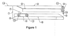
- the geometry of the connecting elements 3 and the front of the panel 2 is designed in such a way as to limit the angular displacement of the connecting elements 3 with respect to the panel 2 at 90 °, this between a vertical position and a substantially horizontal position, the substantially horizontal position being shown at the figure 1 while the vertical position is shown at the figure 2 .
- the connecting elements 3 comprise a second hinge axis 11 around which the manual pallet 4 can pivot freely. In the rest position, shown in FIG. figure 1 , the connecting elements 3 are in the vertical position and the manual pallet 4 is folded horizontally on the panel 2.
- the second hinge axis 11 is advantageously mobile during the deployment of the manual pallet 4.
- the opposite end to that connected to the fixed and rigid panel 2 of the manual pallet 4 and intended to rest on the pavement or the roadway in its deployed position is vis-à-vis the vertical leg of the frame 1.
- This end is also called the front end of the manual pallet 4.
- the facing surfaces of the manual pallet 4 and the vertical leg of the frame 1 advantageously comprise complementary shapes leaving a space between them just sufficient for these surfaces do not rub the l against each other.
- FIG. figure 2 The deployed position of the manual pallet 4 is shown in FIG. figure 2 . This position is reached by rotating the manual pallet 4 around the second hinge axis 11 and the connecting elements 3 around the first hinge axis 10. The connecting elements 3 are then locked in a horizontal position.
- the pivoting of the pallet 4 around the second hinge axis 11 is not limited, this pivoting continues until the previously mentioned front end of the manual pallet 4 is resting on the sidewalk or pavement, the pallet manual 4 is then inclined downward.
- the hinge pins 10 and 11 can be combined if a simple piano hinge is used as articulation between the manual pallet 4 and the rigid and fixed panel 2, the hinge also replacing the connecting elements. 3.
- the front end of the manual pallet 4 is of beveled shape pointing towards the sidewalk or the roadway as well as the upper rear part of the chassis 1.
- the facing surfaces of the manual pallet 4 and the vertical leg of the frame comprising complementary shapes leaving a space between them just enough for these surfaces do not rub against each other
- detection means may warn a central control unit of the transport means to lock the brakes of the transport means until the manual pallet 4 is in its rest position.
- the manual pallet 4 with a gripping handle retracted in the thickness of the manual pallet 4 or provide a simple hole to ensure the passage and action of a traction element allows easy handling manual pallet 4 and maneuver without excessive effort.
- a locking device of the handle and / or the manual pallet 4 in the rest position can also be provided to prohibit its manipulation by unauthorized or malicious people.
- the shape of the automatic pallet 8 is substantially equivalent to the shape of the manual pallet 4 with its front end intended to meet the sidewalk or the pavement in its unfolded position of beveled shape. Its rear end can integrate a second axis of articulation 12 called automatic ramp, this axis being said second axis in analogy with the second axis of articulation 10 of the manual pallet 4.
- the links 6 can be provided at the rear end of the automatic pallet 8 a set of rods 6, the links extending parallel to each other and spaced apart.
- the links 6 have a first articulated end with the rear end of the automatic pallet 8 around the second axis of articulation 12 of automatic ramp.
- the other end of the rods 6 is articulated about an axis said first axis of articulation 13 of automatic ramp extending parallel to the second axis 12 of automatic ramp.
- the second hinge axis 12 is movable with the automatic pallet 8 while the first hinge axis 13 is movable by being secured to a carriage 5 which will now be described.
- a carriage 5 which pushes the rods 6 towards the outside of the transport means, this by sliding on the lower part of the frame 1, advantageously a horizontal sliding for example, if necessary, on the horizontal branch that includes the chassis 1.
- the carriage 5 then drives the first axis of articulation 13 automatic ramp.
- the carriage 5 can be moved in translation by a drive device of the chain, belt, worm, cylinder or other type.
- each link 6 with a pivoting hook 7.
- the hook 7 is provided with an open receiving groove disposed towards the end of the rod 6 hinged with the carriage 5.
- the hook 7 can extend in the length of the link 6 associated with it being integral and being articulated around the second articulation axis 12 of automatic ramp secured to the automatic pallet 8.
- the automatic pallet 8 is then positioned with its front end resting on the sidewalk or the roadway and its rear end at the upper part of the frame 1 which is then made at least by the manual pallet 4 in the rest position not deployed because no used, this manual pallet 4 then being substantially horizontal.
- the abutment axis 9 of the automatic pallet 8 and the first hinge axis 10 of the manual pallet 4 can be merged then being the same.
- the final deployed position of the automatic pallet 8 shown at the figure 3 is reached when the rods 6 are vertical and the rear end of the automatic pallet 8 is at the floor of the means of transport.
- the corresponding position of the carriage 5 is advantageously detected by an end-of-travel sensor.
- the automatic pallet 8 In its deployed position, the automatic pallet 8 then forms the gently inclined inclined plane necessary for the passage of a wheelchair user from the pavement or roadway to the inside of the means of transport. At the climb, the wheelchair of the user walks on the automatic pallet 8, then on the manual pallet 4 then not deployed and forming a large portion of the upper part of the frame 1 and finally on the upper part of the rear of the frame 1 which is at the floor of the means of transport.
- the automatic pallet 8 can integrate all the functions and security requirements for this kind of equipment. It can be cited without being limiting a sensitive edge on the front end of the automatic pallet 8, a sensitive mat on its upper face acting as a raceway for the wheelchair of the user, an overcurrent detection of the motor moving in translation the carriage 5, a rest position sensor with the automatic pallet 8 completely retracted into the chassis 1 in order to immobilize the means of transport if the automatic pallet 8 is not in this position.
Landscapes
- Engineering & Computer Science (AREA)
- Transportation (AREA)
- Mechanical Engineering (AREA)
- Health & Medical Sciences (AREA)
- Public Health (AREA)
- Life Sciences & Earth Sciences (AREA)
- Animal Behavior & Ethology (AREA)
- General Health & Medical Sciences (AREA)
- Veterinary Medicine (AREA)
- Escalators And Moving Walkways (AREA)
Applications Claiming Priority (1)
| Application Number | Priority Date | Filing Date | Title |
|---|---|---|---|
| FR1301888A FR3009525B1 (fr) | 2013-08-06 | 2013-08-06 | Systeme a rampe double manuelle et automatique pour usager en fauteuil roulant dans un moyen de transport |
Publications (1)
| Publication Number | Publication Date |
|---|---|
| EP2851240A1 true EP2851240A1 (de) | 2015-03-25 |
Family
ID=49667211
Family Applications (1)
| Application Number | Title | Priority Date | Filing Date |
|---|---|---|---|
| EP14002759.0A Withdrawn EP2851240A1 (de) | 2013-08-06 | 2014-08-06 | System manuelle und automatische Doppel Rampe für Rollstuhlfahrer in einem Transportmittel |
Country Status (2)
| Country | Link |
|---|---|
| EP (1) | EP2851240A1 (de) |
| FR (1) | FR3009525B1 (de) |
Citations (3)
| Publication number | Priority date | Publication date | Assignee | Title |
|---|---|---|---|---|
| US20020110444A1 (en) * | 2001-01-26 | 2002-08-15 | Navarro Sebastian Garcia | Drive mechanism for a vehicle access system |
| FR2887504A1 (fr) * | 2005-06-28 | 2006-12-29 | Metalic Sarl | Rampe escamotable d'acces a un vehicule, vehicule de transport public notamment |
| DE202007006863U1 (de) * | 2007-05-10 | 2007-08-23 | Schliess- Und Sicherungssysteme Gmbh | Ein- und Ausstiegshilfe für Fahrzeuge des Personenverkehrs |
-
2013
- 2013-08-06 FR FR1301888A patent/FR3009525B1/fr active Active
-
2014
- 2014-08-06 EP EP14002759.0A patent/EP2851240A1/de not_active Withdrawn
Patent Citations (3)
| Publication number | Priority date | Publication date | Assignee | Title |
|---|---|---|---|---|
| US20020110444A1 (en) * | 2001-01-26 | 2002-08-15 | Navarro Sebastian Garcia | Drive mechanism for a vehicle access system |
| FR2887504A1 (fr) * | 2005-06-28 | 2006-12-29 | Metalic Sarl | Rampe escamotable d'acces a un vehicule, vehicule de transport public notamment |
| DE202007006863U1 (de) * | 2007-05-10 | 2007-08-23 | Schliess- Und Sicherungssysteme Gmbh | Ein- und Ausstiegshilfe für Fahrzeuge des Personenverkehrs |
Also Published As
| Publication number | Publication date |
|---|---|
| FR3009525A1 (fr) | 2015-02-13 |
| FR3009525B1 (fr) | 2015-09-04 |
Similar Documents
| Publication | Publication Date | Title |
|---|---|---|
| EP2663705B1 (de) | Handgriff eines öffnungselements eines fahrzeugs mit einem griffteil | |
| FR3018052A1 (fr) | Machine de travail, notamment camion a benne | |
| EP3450363B1 (de) | Gesicherte rampe zum entladen von abfall aus einem fahrzeug in einer lagereinrichtung | |
| EP2917069B1 (de) | Anordnung zur formung einer zugangsrampe für personen mit eingeschränkter mobilität und damit ausgestattetes fahrzeug | |
| EP2810825B1 (de) | Vorrichtung zum Rückwärtssehen für ein Kraftfahrzeug | |
| EP2252493B1 (de) | Fahrzeug zur handhabung von schwerlasten, insbesondere schienen, und verwendung eines derartigen fahrzeuges in gegenwart eines fahrleitungssystems | |
| EP2851240A1 (de) | System manuelle und automatische Doppel Rampe für Rollstuhlfahrer in einem Transportmittel | |
| EP2958771B1 (de) | Nutzfahrzeug mit modularem aufbau | |
| EP4408785B1 (de) | Maschine zur handhabung einer last oder einer person | |
| FR3094705A1 (fr) | Niveleur de quai avec éléments latéraux réglables, poste d'accostage et centre de distribution équipé de celui-ci, ainsi que méthode associée | |
| FR3074157A1 (fr) | Equipement amovible d'acces pour intervention sur panneau en hauteur | |
| WO2017042391A1 (fr) | Système d'ouverture de hayon présentant plusieurs cinématiques d'ouverture | |
| FR2878433A1 (fr) | Dispositif de transfert et de chargement de fauteuil roulant a bord d'un vehicule | |
| FR2999551A1 (fr) | Equipement de securite pour quai, systeme et procedes afferents | |
| EP3260405B1 (de) | Vorrichtung zur immobilisierung einer beweglichen struktur mit lastaufnahmestützen, und entsprechendes anwendungsverfahren | |
| EP2228262A1 (de) | Unterstützungsvorrichtung für das Be-oder Entladen eines Fahrzeugkofferraums und Fahrzeug hierfür | |
| EP0377222B1 (de) | Ausziehleiter auf einem Fahrgestell | |
| EP0802143A1 (de) | Mechanische Sicherheitsvorrichtung für den Benutzer eines Aufzuges zwischen zwei Stockwerken | |
| WO2024047306A1 (fr) | Engin de manutention de charge | |
| FR3020351A1 (fr) | Dispositif de chargement en dechets d'une benne de dechetterie depuis une plateforme | |
| EP2756989B1 (de) | Halte- und/oder Verstauungssystem von Waren, insbesondere für Straßentransportfahrzeuge | |
| EP3524457B1 (de) | Lastkraftwagen mit kipperaufbau, und abdeckvorrichtung, mit der ein solcher lkw ausgerüstet ist | |
| FR2918322A1 (fr) | Betaillere comprenant au moins un plancher mobile | |
| FR2922169A1 (fr) | Systeme de galerie escamotable pour vehicule automobile, commande par un levier, et vehicule correspondant | |
| FR2857638A1 (fr) | Dispositif de relevage d'un moyen de protection arriere d'un vehicule industriel et vehicule industriel equipe d'un tel dispositif |
Legal Events
| Date | Code | Title | Description |
|---|---|---|---|
| PUAI | Public reference made under article 153(3) epc to a published international application that has entered the european phase |
Free format text: ORIGINAL CODE: 0009012 |
|
| 17P | Request for examination filed |
Effective date: 20140806 |
|
| AK | Designated contracting states |
Kind code of ref document: A1 Designated state(s): AL AT BE BG CH CY CZ DE DK EE ES FI FR GB GR HR HU IE IS IT LI LT LU LV MC MK MT NL NO PL PT RO RS SE SI SK SM TR |
|
| AX | Request for extension of the european patent |
Extension state: BA ME |
|
| R17P | Request for examination filed (corrected) |
Effective date: 20160108 |
|
| RBV | Designated contracting states (corrected) |
Designated state(s): AL AT BE BG CH CY CZ DE DK EE ES FI FR GB GR HR HU IE IS IT LI LT LU LV MC MK MT NL NO PL PT RO RS SE SI SK SM TR |
|
| STAA | Information on the status of an ep patent application or granted ep patent |
Free format text: STATUS: THE APPLICATION IS DEEMED TO BE WITHDRAWN |
|
| 18D | Application deemed to be withdrawn |
Effective date: 20180301 |