EP2851235A2 - Anordnung zum Verbinden von Stromschienen-Elementen eines Fahrleitungssystems - Google Patents
Anordnung zum Verbinden von Stromschienen-Elementen eines Fahrleitungssystems Download PDFInfo
- Publication number
- EP2851235A2 EP2851235A2 EP14185236.8A EP14185236A EP2851235A2 EP 2851235 A2 EP2851235 A2 EP 2851235A2 EP 14185236 A EP14185236 A EP 14185236A EP 2851235 A2 EP2851235 A2 EP 2851235A2
- Authority
- EP
- European Patent Office
- Prior art keywords
- contact
- busbar
- connection profile
- elements
- arrangement according
- Prior art date
- Legal status (The legal status is an assumption and is not a legal conclusion. Google has not performed a legal analysis and makes no representation as to the accuracy of the status listed.)
- Granted
Links
Images

Classifications
-
- B—PERFORMING OPERATIONS; TRANSPORTING
- B60—VEHICLES IN GENERAL
- B60M—POWER SUPPLY LINES, AND DEVICES ALONG RAILS, FOR ELECTRICALLY- PROPELLED VEHICLES
- B60M1/00—Power supply lines for contact with collector on vehicle
- B60M1/30—Power rails
- B60M1/305—Joints
Definitions
- the invention relates to an arrangement for connecting busbar elements of a catenary system, which are arranged at a collision distance from one another and have a horizontally oriented in the installed position carrier.
- busbars For traction power supply electrically operated tracks are known overhead catenaries busbars that are part of a catenary system. For the establishment of a route multiple busbars are interconnected because the busbars for transport reasons have a maximum length.
- the individual busbar pieces of a route are hereinafter referred to as busbar elements.
- the busbar elements are subject to changes in length due to changes in ambient temperature and changes in current, so that without a length compensation only a limited number of busbar elements can be joined together in bursts.
- the invention has for its object to provide an arrangement for connecting busbar elements of a catenary system, which has a simple and safe structure.
- connection of the individual busbar elements of a catenary system in a collision distance from each other takes place in the inventive arrangement with a U-shaped connection profile, which has a central leg and two outer legs and is characterized by a relatively low weight and high rigidity.
- the middle leg of the connection profile is displaceable with the carrier of the first busbar element in the longitudinal direction of the busbar element and fixedly connected to the carrier of the second busbar element, so that a length compensation due to changes in the ambient temperature or the current is possible.
- the outer limbs of the connection profile laterally comprise the busbar elements, so that the electrical connection can take place in the surrounding area of the connection profile and the busbar elements. Therefore, the arrangement forms a compact unit.
- contact elements are electrically connected, which are resiliently biased to the contact rails.
- the contact elements and contact rails allow a length compensation over a large expansion range without the risk of cable breakage. Furthermore, only a small space is claimed.
- connection arrangement provides for electrical busbar elements, which have two in the installed position of the upper carrier downwardly extending legs, an electrical connection of the two legs of the first busbar element, which is longitudinally displaceably connected to the connection profile, each with at least one extending in the longitudinal direction of the busbar element contact rail and an electrical connection of the outer legs of the U-shaped connection profile, each with at least one resiliently biased to the contact rail contact element ,
- electrical busbar elements which have two in the installed position of the upper carrier downwardly extending legs, an electrical connection of the two legs of the first busbar element, which is longitudinally displaceably connected to the connection profile, each with at least one extending in the longitudinal direction of the busbar element contact rail and an electrical connection of the outer legs of the U-shaped connection profile, each with at least one resiliently biased to the contact rail contact element ,
- one contact element and one contact rail on each side of the busbar element are sufficient in each case.
- a further preferred embodiment provides that the at least one contact element is electrically connected to the outer leg of the connection profile by means of at least one flexible conductor, one end of which is electrically connected to the contact element and the other end is electrically connected to the outer leg of the connection profile.
- the electrical connection between the connection profile and the contact element preferably takes place with a plurality of flexible conductors, in particular copper cables. This cable bridge is not used in the connection arrangement according to the invention to compensate for the changes in length of the busbar elements, but only to compensate for minor tolerances.
- the at least one contact element preferably has a resiliently biased against the contact rail contact plate on which at least one contact piece is attached, which contacts the contact rail.
- On the outer legs of the connection profile clamping members are preferably provided, with which one ends of the flexible conductors are connected to the outer legs of the connection profile, and on the contact plates of the contact elements clamping parts are provided, with which the other ends of the flexible conductors to the contact plates are connected.
- the clamping parts and contact plates are arranged in housing parts, which are provided on the outer limbs of the connection profile. This protects the electrical connections from dirt and moisture.
- the housing parts attached laterally to the connection profiles can be flat so that only little space is available in the horizontal direction is claimed. In any case, the overall height is not increased, which allows the use of the connection assembly according to the invention in tunnels in which a low overall height is required.
- the upper carrier of the busbar elements on the upper side in the longitudinal direction of the busbar elements extending recess for receiving a guide plate, wherein the central leg of the connection profile with the upper carrier of the first busbar element by means of guide pins longitudinally displaceable is connected, which are bolted to the guide plate, which is inserted into the recess of the first busbar element.
- the middle leg of the connection profile and the upper support of the first busbar element sliding elements are preferably arranged so that busbar element and connection profile can move against each other largely wear.
- the sliding elements can be part of a replaceable unit which is attached to the connection profile, so that the maintenance effort is low.
- the upper carrier of the second busbar element and the middle leg of the connection profile are preferably screwed tightly together, so that a relative movement is not possible.
- a further preferred embodiment provides two parallel arranged skids, which are fastened in the transition region between the first and second busbar element on the legs of the busbar elements.
- the respective ends of the skids are arranged with the contact wire or overlapping each other.
- the runners are preferably arranged at a small distance parallel to each other, so that they can be run over quickly by the pantograph.
- Fig. 1 shows the two busbar elements 1, 2 and the connection profile 3 in the side view.
- a busbar element which is hereinafter referred to as the first busbar element 1, slidably connected in the longitudinal direction of the busbar element with the connection profile 3, while the in Fig. 1 on the right side busbar element, which is hereinafter referred to as the second busbar element 2, is fixedly connected to the connection profile 3. Consequently, a compensation of length changes only on the left side is possible.
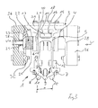
- Fig. 3 shows the connection arrangement in a partially sectional view.
- the busbar elements 1, 2 have an upper horizontal carrier 4 in the installed position, from which two parallel outer legs 5, 6 extend downwards.
- To the outer legs 5, 6 of the busbar element 1, 2 join inwardly extending clamping arms 7, 8, which hold a contact wire 9 by clamping outside the transition region of the busbar elements.
- the two skids 10, 11 extend at a predetermined distance a parallel to each other in the longitudinal direction of the busbar elements, wherein one end of the one skid 10 with the contact wire 9 of a busbar element 1 and one end of the other running skids 11 overlaps with the contact wire 9 of the other busbar element 2 and the other ends of the skids 10, 11 overlap each other, so that the contact wire route is not interrupted.
- the upper support 4 of the first busbar element 1 rests with the interposition of sliding elements 14, 15 on the underside of the middle leg 3A of the connection profile 3.
- the carrier 4 has at the top a extending in the longitudinal direction of the busbar element recess 16 into which a guide plate 17 is inserted.
- the guide plate 17 is screwed with guide pin 18 such that the upper carrier 4 of the busbar element 1 and the connecting profile 3 are connected to each other in the longitudinal direction displaceable.
- the outer legs 3A, 3B of the connection profile 3 laterally comprise the outer legs 5, 6 of the busbar elements 1, 2.
- connection profile 3 The electrical connection of the first busbar element 1 to the one end of the connection profile 3 will be described below.
- a contact rail 21 which extends in the longitudinal direction of the busbar element 1.
- a contact rail 21 which extends in the longitudinal direction of the busbar element 1.
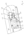
- the contact elements 22 on both sides of the busbar element 1 each have an outer contact plate 23, on which an inner contact piece 24, in particular a metal carbon is fixed, which contacts with the associated contact rail 21.
- connection profile 3 contact plates 23 are resiliently biased against the contact rails 21 ( Fig. 4 ).
- the lateral recesses 25 of the connection profile 3 are sealed with housing parts 26.
- the bias voltage is applied to seated on guide pins 28 springs 29, which are supported on the one hand on the inside of the housing parts 26 and on the other hand on the contact plates 23 ( Fig. 4 ).
- the other ends of the copper cables 30 are electrically connected to the contact plates 23 attached to the contact plates 23 clamping members 33 with the contact plates 23, so that the current from the contact plates 23 via the copper cables 30 to the Connection profile 3 can flow, which is electrically connected to the second busbar element 2.
- connection profile 3 and the second busbar element 2 is not critical, since the second busbar element 2 and the connection profile 3 can not move relative to one another.
- the electrical connection can be designed differently. Both components can be screwed together to produce the electrical connection.
Landscapes
- Engineering & Computer Science (AREA)
- Mechanical Engineering (AREA)
- Current-Collector Devices For Electrically Propelled Vehicles (AREA)
- Supply And Distribution Of Alternating Current (AREA)
Abstract
Description
- Die Erfindung betrifft eine Anordnung zum Verbinden von Stromschienen-Elementen eines Fahrleitungssystems, die in einem Stoßabstand zueinander angeordnet sind und einen in der Einbaulage horizontal ausgerichteten Träger aufweisen.
- Zur Fahrstromversorgung elektrisch betriebener Bahnen sind neben Oberleitungen Stromschienen bekannt, die Teil eines Fahrleitungssystems sind. Für die Errichtung einer Fahrstrecke werden mehrere Stromschienen miteinander verbunden, da die Stromschienen aus Transportgründen eine maximale Länge haben. Die einzelnen Stromschienenstücke einer Fahrstrecke werden nachfolgend als Stromschienen-Elemente bezeichnet.
- Die Stromschienen-Elemente sind aufgrund von Änderungen der Umgebungstemperatur sowie Änderungen der Stromstärke Längenänderungen unterworfen, so dass ohne einen Längenausgleich nur eine begrenzte Anzahl von Stromschienen-Elementen Stoß an Stoß aneinandergefügt werden können.
- Aus der
WO 2012/130582 A2 ist bekannt, die Stromschienen-Elemente nicht direkt aneinander zufügen, sondern in einem Stoßabstand zueinander anzuordnen, so dass sich die Stromschienen-Elemente in einem Überlappungsbereich ausdehnen können. - Bei der Anordnung der Stromschienen-Elemente in einem Stoßabstand zueinander stellt sich dass Problem der elektrischen Verbindung der Stromschienen-Elemente. Es ist bekannt, die Stromschienen-Elemente mit einer Kabelbrücke elektrisch zu verbinden. Eine Kabelbrücke lässt aber nur eine eingeschränkte Bewegung der Stromschienen-Elemente zu. Weiterhin beansprucht eine Kabelbrücke relativ viel Raum, da das Kabel wegen der Bewegung der Stromschienen-Elemente als Schleife gelegt werden muss. Darüber hinaus sind die Anschüsse der Kabel stark bruchgefährdet.
- Der Erfindung liegt die Aufgabe zugrunde, eine Anordnung zum Verbinden von Stromschienen-Elementen eines Fahrleitungssystems zu schaffen, die einen einfachen und sicheren Aufbau hat.
- Die Lösung dieser Aufgabe erfolgt erfindungsgemäß mit den Merkmalen des Patentanspruchs 1. Die Gegenstände der abhängigen Ansprüche betreffen vorteilhafte Ausführungsformen der Erfindung.
- Die Verbindung der einzelnen Stromschienen-Elemente eines Fahrleitungssystems in einem Stoßabstand zueinander erfolgt bei der erfindungsgemäßen Anordnung mit einem U-förmigen Verbindungsprofil, das einen mittleren Schenkel und zwei äußere Schenkel aufweist und sich durch ein relativ geringes Gewicht und eine hohe Steifigkeit auszeichnet. Der mittlere Schenkel des Verbindungsprofils ist mit dem Träger des ersten Stromschienen-Elements in Längsrichtung des Stromschienen-Elements verschiebbar und mit dem Träger des zweiten Stromschienen-Elements fest verbunden ist, so dass ein Längenausgleich aufgrund von Änderungen der Umgebungstemperatur oder der Stromstärke möglich ist. Dabei umfassen die äußeren Schenkel des Verbindungsprofils die Stromschienen-Elemente seitlich, so dass in dem Umfassungsbereich des Verbindungsprofils und der Stromschienen-Elemente die elektrische Verbindung erfolgen kann. Daher bildet die Anordnung eine kompakte Einheit.
- Bei der erfindungsgemäßen Anordnung sind mit dem ersten Stromschienen-Element sich in Längsrichtung des Stromschienen-Elements erstreckende Kontaktschienen elektrisch verbunden, und mit den äußeren Schenkeln des U-förmigen Verbindungsprofils sind Kontaktelemente elektrisch verbunden, die auf die Kontaktschienen federnd vorgespannt sind. Die Kontaktelemente und Kontaktschienen erlauben einen Längenausgleich über einen großen Dehnungsbereich ohne die Gefahr eines Kabelbruchs. Weiterhin wird ein nur geringer Raum beansprucht.
- Eine bevorzugte Ausführungsform der erfindungsgemäßen Verbindungsanordnung sieht für Stromschienen-Elemente, die zwei sich in der Einbaulage von dem oberen Träger nach unten erstreckende Schenkel aufweisen, eine elektrische Verbindung der beiden Schenkel des ersten Stromschienen-Elements, das längsverschiebbar mit dem Verbindungsprofil verbunden ist, mit jeweils mindestens einer sich in Längsrichtung des Stromschienen-Elements erstreckenden Kontaktschiene und eine elektrische Verbindung der äußeren Schenkel des U-förmiges Verbindungsprofils mit jeweils mindestens einem auf die Kontaktschiene federnd vorgespannten Kontaktelement vor. In der Praxis sind jeweils ein Kontaktelement und jeweils eine Kontaktschiene auf einer Seite des Stromschienen-Elements ausreichend.
- Eine weitere bevorzugte Ausführungsform sieht vor, dass das mindestens eine Kontaktelement mit dem äußeren Schenkel des Verbindungsprofils mittels mindestens eines flexiblen Leiters elektrisch verbunden ist, von dem das eine Ende elektrisch mit dem Kontaktelement und das andere Ende elektrisch mit dem äußeren Schenkel des Verbindungsprofils verbunden ist. Vorzugsweise erfolgt die elektrische Verbindung von Verbindungsprofil und Kontaktelement mit mehreren flexiblen Leitern, insbesondere Kupferseilen. Diese Kabelbrücke dient bei der erfindungsgemäßen Verbindungsanordnung nicht dem Ausgleich der Längenänderungen der Stromschienen-Elemente, sondern nur zum Ausgleich geringfügiger Toleranzen.
- Das mindestens eine Kontaktelement weist vorzugsweise eine federnd gegen die Kontaktschiene vorgespannte Kontaktplatte auf, an der mindestens ein Kontaktstück befestigt ist, das die Kontaktschiene kontaktiert. An den äußeren Schenkeln des Verbindungsprofils sind vorzugsweise Klemmteile vorgesehen, mit denen die einen Enden der flexiblen Leiter an den äußeren Schenkeln des Verbindungsprofils angeschlossen sind, und an den Kontaktplatten der Kontaktelemente sind Klemmteile vorgesehen sind, mit denen die anderen Enden der flexiblen Leiter an den Kontaktplatten angeschlossen sind. Dadurch ist eine einfache Montage bzw. Demontage der Bauteile möglich.
- Zum Schutz vor äußeren Einflüssen sind die Klemmteile und Kontaktplatten in Gehäuseteilen angeordnet sind, die an den äußeren Schenkeln des Verbindungsprofils vorgesehen sind. Dadurch sind die elektrischen Verbindungen vor Schmutz und Feuchtigkeit geschützt. Die seitlich an den Verbindungsprofilen angebrachten Gehäuseteile können flach sein, so dass in horizontaler Richtung nur wenig Raum beansprucht wird. Auf jeden Fall wird die Bauhöhe nicht erhöht, was den Einsatz der erfindungsgemäßen Verbindungsanordnung in Tunneln erlaubt, in denen eine nur geringe Bauhöhe gefordert wird.
- Bei einer weiteren bevorzugten Ausführungsform weist der obere Träger der Stromschienen-Elemente an der Oberseite eine sich in Längsrichtung der Stromschienen-Elemente erstreckende Ausnehmung zur Aufnahme einer Führungsplatte auf, wobei der mittlere Schenkel des Verbindungsprofils mit dem oberen Träger des ersten Stromschienen-Elements mittels Führungsbolzen längsverschiebbar verbunden ist, die mit der Führungsplatte verschraubt sind, die in die Ausnehmung des ersten Stromschienen-Elements eingesetzt ist. Zwischen dem mittleren Schenkel des Verbindungsprofils und dem oberen Träger des ersten Stromschienen-Elements sind vorzugsweise Gleitelemente angeordnet, so dass sich Stromschienen-Element und Verbindungsprofil weitgehend verschleißfrei gegeneinander bewegen können. Die Gleitelemente können Teil einer austauschbaren Einheit sein, die an dem Verbindungsprofil befestigt wird, so dass der Wartungsaufwand gering ist.
- Der obere Träger des zweiten Stromschienen-Elements und der mittlere Schenkel des Verbindungsprofils sind vorzugsweise fest miteinander verschraubt, so dass eine Relativbewegung nicht möglich ist.
- Eine weitere bevorzugte Ausführungsform sieht zwei parallel zueinander angeordnete Fahrkufen vor, die im Übergangsbereich zwischen dem ersten und zweiten Stromschienen-Element an den Schenkeln der Stromschienen-Elemente befestigt sind. Damit eine saubere Übergabe des Pantografen von der festen auf die geführte Seite gewährleistet ist, sind die jeweiligen Enden der Fahrkufen mit dem Fahrdraht bzw. einander überlappend angeordnet. Die Fahrkufen sind vorzugsweise in einem geringen Abstand parallel zueinander angeordnet, so dass sie von dem Pantografen schnell überfahren werden können.
- Im Folgenden wird ein Ausführungsbeispiel der Erfindung unter Bezugnahme auf die Zeichnungen näher erläutert.
- Es zeigen:
- Fig. 1
- ein Ausführungsbeispiel der erfindungsgemäßen Anordnung zum Verbinden von zwei Stromschienen-Elementen in der Seitenansicht,
- Fig. 2
- die Anordnung zum Verbinden von zwei Stromschienen-Elementen in der Draufsicht,
- Fig. 3
- die Verbindungsanordnung in teilweiser geschnittener Darstellung und
- Fig. 4
- eine Ansicht der Verbindungsanordnung von
Fig. 1 aus der Richtung des Pfeils V bei abgenommenem Gehäuseteil. - Für die Errichtung eines Fahrleitungssystems werden die einzelnen Stromschienen-Elemente 1, 2 mit den Stirnseiten in einem vorgegebenen Stoßabstand, der zwischen 500 mm und 1000 mm liegen kann, zueinander angeordnet. Die stirnseitige Verbindung erfolgt mit einem U-förmigen Verbindungsprofil 3, insbesondere ein Aluminium-Profil, das einen mittleren Schenkel 3A und zwei äußere Schenkel 3B, 3C aufweist (
Fig. 3 ). -
Fig. 1 zeigt die beiden Stromschienen-Elemente 1, 2 und das Verbindungsprofil 3 in der Seitenansicht. Auf der inFig. 1 linken Seite ist das eine Stromschienen-Element, das nachfolgend als erstes Stromschienen-Element 1 bezeichnet wird, in Längsrichtung des Stromschienen-Elements verschiebbar mit dem Verbindungsprofil 3 verbunden, während das inFig. 1 auf der rechten Seite gezeigte Stromschienen-Element, das nachfolgend als zweites Stromschienen-Element 2 bezeichnet wird, fest mit dem Verbindungsprofil 3 verbunden ist. Folglich ist ein Ausgleich von Längenänderungen nur auf der linken Seite möglich. -
Fig. 3 zeigt die Verbindungsanordnung in teilweiser geschnittener Darstellung. Die Stromschienen-Elemente 1, 2 weisen einen in der Einbaulage oberen, horizontalen Träger 4 auf, von dem sich zwei parallele äußere Schenkel 5, 6 nach unten erstrecken. An die äußeren Schenkel 5, 6 des Stromschienen-Elements 1, 2 schließen sich nach innen erstreckende Klemmarme 7, 8 an, die außerhalb des Übergangsbereichs der Stromschienen-Elemente einen Fahrdraht 9 klemmend halten. - Im Übergangsbereich der Stromschienen-Elemente 1, 2 ist an den äußeren Schenkeln 5, 6 jeweils eine Fahrkufe 10, 11 befestigt. Die Befestigung der Fahrkufen 10, 11 an den äußeren Schenkeln 5, 6 erfolgt mittels geeigneter Befestigungsteile 12, 13. Die beiden Fahrkufen 10, 11 verlaufen in einem vorgegebene Abstand a parallel zueinander in Längsrichtung der Stromschienen-Elemente, wobei das eine Ende der einen Fahrkufe 10 mit dem Fahrdraht 9 des einen Stromschienen-Elements 1 und das eine Ende der anderen Fahrkufe 11 mit dem Fahrdraht 9 des anderen Stromschienen-Elements 2 überlappt und die anderen Enden der Fahrkufen 10, 11 einander überlappen, so das die Fahrdrahtstrecke nicht unterbrochen ist.
- Der obere Träger 4 des ersten Stromschienen-Elements 1 liegt unter Zwischenlage von Gleitelementen 14, 15 an der Unterseite des mittleren Schenkels 3A des Verbindungsprofils 3 an. Der Träger 4 weist an der Oberseite eine sich in Längsrichtung des Stromschienen-Elements erstreckende Ausnehmung 16 auf, in die eine Führungsplatte 17 eingesetzt ist. Die Führungsplatte 17 ist mit Führungsbolzen 18 derart verschraubt, dass der obere Träger 4 des Stromschienen-Elements 1 und das Verbindungsprofil 3 in Längsrichtung verschiebbar miteinander verbunden sind. Dabei umfassen die äußeren Schenkel 3A, 3B des Verbindungsprofils 3 seitlich die äußeren Schenkel 5, 6 der Stromschienen-Elemente 1, 2.
- Die feste Verbindung von dem zweiten Stromschienen-Element 2 und dem Verbindungsprofil 3 erfolgt mittels Befestigungsschrauben 19, die sich durch den mittleren Schenkel 3A des Verbindungsprofils 3 und den oberen Träger 4 des Stromschienen-Elements 2 erstrecken und mit an der Unterseite des Trägers 4 anliegenden Befestigungsplatten verschraubt sind, die in den Figuren nicht dargestellt sind (
Fig. 1 und Fig. 2 ). - Nachfolgend wird die elektrische Verbindung des ersten Stromschienen-Elements 1 mit dem einen Ende des Verbindungsprofils 3 beschrieben.
- An den beiden äußeren Schenkeln 5, 6 des ersten Stromschienen-Elements 1 ist unter Zwischenlage von geeigneten Kontaktmitteln 20, die einen verbesserten elektrischen Kontakt herstellen, jeweils eine Kontaktschiene 21 befestigt, die sich in Längsrichtung des Stromschienen-Elements 1 erstreckt. Auf der Höhe der Kontaktschienen 21 befindet sich an den äußeren Schenkeln 3B, 3C des Verbindungsprofils 3 jeweils ein Kontaktelement 22. Die Kontaktelemente 22 auf beiden Seiten des Stromschienen-Elements 1 weisen jeweils eine äußere Kontaktplatte 23 auf, an der ein inneres Kontaktstück 24, insbesondere eine Metallkohle, befestigt ist, die mit der zugehörigen Kontaktschiene 21 kontaktiert.
- Die in Ausnehmungen 25 der äußeren Schenkel 3B, 3C des Verbindungsprofils 3 angeordneten Kontaktplatten 23 sind federnd gegen die Kontaktschienen 21 vorgespannt (
Fig. 4 ). Die seitlichen Ausnehmungen 25 des Verbindungsprofils 3 sind mit Gehäuseteilen 26 dicht verschlossen. Die Vorspannung wird mit auf Führungsbolzen 28 sitzenden Federn 29 aufgebracht, die sich einerseits an der Innenseite der Gehäuseteile 26 und andererseits an den Kontaktplatten 23 abstützen (Fig. 4 ). - Folglich kann ein Strom über das erste Stromschienen-Element 1, die Kontaktschienen 21, die Kontaktstücke 24 und die Kontaktplatten 23 fließen. Die Herstellung einer elektrischen Verbindung zwischen den beiden Kontaktplatten 23 und den äußeren Schenkeln 3B, 3C des ersten Stromschienen-Elements erfolgt mittels flexibler Leiter 30, insbesondere Kupferseile 30, die einerseits mit der Kontaktplatte 23 und andererseits mit dem äußeren Schenkel 3B, 3C des Verbindungsprofils 3 elektrisch verbunden sind. An den äußeren Schenkeln 3B, 3C des Verbindungsprofils 3 sind Klemmteile 31 befestigt, mit denen die einen Enden der Kupferseile 30 an dem jeweiligen äußeren Schenkel 3B, 3C des Verbindungsprofils 3 unter Zwischenlage von geeigneten Kontaktmitteln 32 angeschlossen sind. Als Kontaktmittel können mit einer Cu-Schicht versehene Al-Platten 32 (Cupal-Blech) Verwendung finden. Die anderen Enden der Kupferseile 30 sind mit an den Kontaktplatten 23 befestigten Klemmteilen 33 mit den Kontaktplatten 23 elektrisch verbunden, so dass der Strom von den Kontaktplatten 23 über die Kupferseile 30 zu dem Verbindungsprofil 3 fließen kann, das elektrisch mit dem zweiten Stromschienen-Element 2 verbunden ist.
- Die elektrische Verbindung des Verbindungsprofils 3 und des zweites Stromschienen-Elements 2 ist unkritisch, da sich das zweite Stromschienen-Element 2 und das Verbindungsprofil 3 nicht gegeneinander bewegen können. Die elektrische Verbindung kann unterschiedlich ausgebildet sein. Beide Bauteile können zur Herstellung der elektrischen Verbindung miteinander verschraubt sein.
Claims (12)
- Anordnung zum Verbinden von Stromschienen-Elementen (1, 2) eines Fahrleitungssystems, die in einem Stoßabstand zueinander angeordnet sind und einen in der Einbaulage horizontal ausgerichteten Träger (4) aufweisen,
dadurch gekennzeichnet, dass
die Verbindungsanordnung ein U-förmiges Verbindungsprofil (3) mit einem mittleren Schenkel (3A) und zwei äußeren Schenkeln (3B, 3C) aufweist, wobei
der mittlere Schenkel (3A) des Verbindungsprofils (3) mit dem Träger (4) des ersten Stromschienen-Elements (1) in Längsrichtung des Stromschienen-Elements verschiebbar und mit dem Träger (4) des zweiten Stromschienen-Elements (2) fest verbunden ist, und die äußeren Schenkel (3B, 3C) des Verbindungsprofils (3) die Stromschienen-Elemente (1, 2) seitlich umfassen, und
mit dem ersten Stromschienen-Element (1) sich in Längsrichtung des Stromschienen-Elements erstreckende Kontaktschienen (21) elektrisch verbunden sind, und mit den äußeren Schenkeln des U-förmigen Verbindungsprofils (3) Kontaktelemente (22) elektrisch verbunden sind, die auf die Kontaktschienen federnd vorgespannt sind. - Anordnung nach Anspruch 1, dadurch gekennzeichnet, dass die Stromschienen-Elemente (1, 2) zwei sich in der Einbaulage von dem oberen Träger (4) nach unten erstreckende Schenkel (5, 6) aufweisen, wobei mit den beiden Schenkeln (5, 6) des ersten Stromschienen-Elements (1) jeweils mindestens eine sich in Längsrichtung des Stromschienen-Elements erstreckende Kontaktschiene (21) elektrisch verbunden ist, und mit den äußeren Schenkeln (3B, 3C) des U-förmiges Verbindungsprofils jeweils mindestens ein auf die Kontaktschiene (21) federnd vorgespanntes Kontaktelement (22) elektrisch verbunden ist.
- Anordnung nach Anspruch 2, dadurch gekennzeichnet, dass das mindestens eine Kontaktelement (22) mit dem äußeren Schenkel (3B, 3C) des Verbindungsprofils (3) mittels mindestens eines flexiblen Leiters (30) elektrisch verbunden ist, von dem das eine Ende elektrisch mit dem Kontaktelement (22) und das andere Ende elektrisch mit dem äußeren Schenkel (3B, 3C) des Verbindungsprofils (3) verbunden ist.
- Anordnung nach Anspruch 2 oder 3, dadurch gekennzeichnet, dass das mindestens eine Kontaktelement (22) eine federnd gegen die Kontaktschiene (21) vorgespannte Kontaktplatte (23) aufweist, an der mindestens ein Kontaktstück (24) befestigt ist, das die Kontaktschiene (21) kontaktiert.
- Anordnung nach Anspruch 4, dadurch gekennzeichnet, dass an den äußeren Schenkeln (3A, 3B) des Verbindungsprofils (3) Klemmteile (31) vorgesehen sind, mit denen die einen Enden der flexiblen Leiter an den äußeren Schenkeln (3B, 3C) des Verbindungsprofils (3) angeschlossen sind, und an den Kontaktplatten (23) der Kontaktelemente Klemmteile (33) vorgesehen ist, mit denen die anderen Enden der flexiblen Leiter (30) an den Kontaktplatten (23) angeschlossen sind.
- Anordnung nach Anspruch 5, dadurch gekennzeichnet, dass die Klemmteile (31, 33) und Kontaktplatten (23) in Gehäuseteilen (26) angeordnet sind, die an den äußeren Schenkeln (3B, 3C) des Verbindungsprofils (3) vorgesehen sind.
- Anordnung nach Anspruch 6, dadurch gekennzeichnet, dass zwischen den Gehäuseteilen (26) und der Kontaktplatte (23) Federn (29) angeordnet sind, die die Kontaktplatte (23) federnd gegen die Kontaktschiene (21) vorspannen.
- Anordnung nach einem der Ansprüche 1 bis 7, dadurch gekennzeichnet, dass der obere Träger (4) der Stromschienen-Elemente (1, 2) an der Oberseite eine sich in Längsrichtung der Stromschienen-Elemente erstreckende Ausnehmung (16) zur Aufnahme einer Führungsplatte (17) aufweist, wobei der mittlere Schenkel (3A) des Verbindungsprofils (3) mit dem oberen Träger (4) des ersten Stromschienen-Elements (1) mittels Führungsbolzen (18) längsverschiebbar verbunden ist, die mit der Führungsplatte (17) verschraubt sind, die in die Ausnehmung (16) des ersten Stromschienen-Elements (1) eingesetzt ist.
- Anordnung nach Anspruch 8, dadurch gekennzeichnet, dass zwischen dem mittleren Schenkel (3A) des Verbindungsprofils (3) und dem oberen Träger (4) des ersten Stromschienen-Elements (1) Gleitelemente (14, 15) angeordnet sind.
- Anordnung nach einem der Ansprüche 1 bis 9, dadurch gekennzeichnet, dass der obere Träger (4) des zweiten Stromschienen-Elements (2) und der mittlere Schenkel (3A) des Verbindungsprofils (3) miteinander verschraubt sind.
- Anordnung nach einem der Ansprüche 2 bis 10, dadurch gekennzeichnet, dass sich an die Schenkel (5, 6) der Stromschienen-Elemente (1, 2) nach innen erstreckende Klemmarme (7, 8) anschließen, die einen Fahrdraht (9) klemmend halten.
- Anordnung nach einem der Ansprüche 2 bis 11, dadurch gekennzeichnet, dass im Übergangsbereich zwischen dem ersten und zweiten Stromschienen-Element (1, 2) an den Schenkeln (5, 6) der Stromschienen-Elemente zwei parallel zueinander angeordnete Fahrkufen (10, 11) befestigt sind, wobei die einen Enden der Fahrkufen (10, 11) mit dem Fahrdraht (9) und die anderen Enden der Fahrkufen (10, 11) einander überlappen.
Priority Applications (2)
| Application Number | Priority Date | Filing Date | Title |
|---|---|---|---|
| PL14185236T PL2851235T3 (pl) | 2013-09-23 | 2014-09-17 | Układ do łączenia elementów szyn energetycznych sieci trakcyjnej |
| HRP20201716TT HRP20201716T1 (hr) | 2013-09-23 | 2020-10-23 | Uređaj za spajanje elemenata elektrificiranih tračnica kod kontaktnog sustava voznih vodova |
Applications Claiming Priority (1)
| Application Number | Priority Date | Filing Date | Title |
|---|---|---|---|
| DE102013015874.5A DE102013015874B3 (de) | 2013-09-23 | 2013-09-23 | Anordnung zum Verbinden von Stromschienen-Elementen eines Fahrleitungssystems |
Publications (3)
| Publication Number | Publication Date |
|---|---|
| EP2851235A2 true EP2851235A2 (de) | 2015-03-25 |
| EP2851235A3 EP2851235A3 (de) | 2015-10-21 |
| EP2851235B1 EP2851235B1 (de) | 2020-08-26 |
Family
ID=51584965
Family Applications (1)
| Application Number | Title | Priority Date | Filing Date |
|---|---|---|---|
| EP14185236.8A Active EP2851235B1 (de) | 2013-09-23 | 2014-09-17 | Anordnung zum Verbinden von Stromschienen-Elementen eines Fahrleitungssystems |
Country Status (10)
| Country | Link |
|---|---|
| EP (1) | EP2851235B1 (de) |
| KR (1) | KR102293167B1 (de) |
| DE (1) | DE102013015874B3 (de) |
| DK (1) | DK2851235T3 (de) |
| ES (1) | ES2831608T3 (de) |
| HR (1) | HRP20201716T1 (de) |
| HU (1) | HUE050982T2 (de) |
| LT (1) | LT2851235T (de) |
| PL (1) | PL2851235T3 (de) |
| PT (1) | PT2851235T (de) |
Cited By (1)
| Publication number | Priority date | Publication date | Assignee | Title |
|---|---|---|---|---|
| CN117962703A (zh) * | 2024-04-01 | 2024-05-03 | 中铁建电气化局集团轨道交通器材有限公司 | 一种刚性接触网导线局部磨损的修正装置 |
Families Citing this family (2)
| Publication number | Priority date | Publication date | Assignee | Title |
|---|---|---|---|---|
| CN105128702B (zh) * | 2015-08-26 | 2017-08-08 | 苏州东玉华电气有限公司 | 一种无卡阻刚性悬挂接触网汇流排导滑系列装置 |
| DE102017115137A1 (de) * | 2017-07-06 | 2019-01-10 | Dr. Ing. H.C. F. Porsche Aktiengesellschaft | Kontaktschieneneinrichtung für ein wenigstens teilweise elektrisch angetriebenes Fahrzeug |
Citations (1)
| Publication number | Priority date | Publication date | Assignee | Title |
|---|---|---|---|---|
| WO2012130582A2 (de) | 2011-03-29 | 2012-10-04 | Siemens Aktiengesellschaft | Dehnverbindungsanordnung aneinanderstossender stromschienen einer oberleitungsanlage für elektrische triebfahrzeuge |
Family Cites Families (7)
| Publication number | Priority date | Publication date | Assignee | Title |
|---|---|---|---|---|
| JP3322013B2 (ja) * | 1993-11-26 | 2002-09-09 | 日立電線株式会社 | トロリー導体用接続装置 |
| JPH11192864A (ja) * | 1998-01-05 | 1999-07-21 | Furukawa Electric Co Ltd:The | 絶縁トロリの伸縮接続部 |
| JP2000318493A (ja) * | 1999-05-10 | 2000-11-21 | Sumitomo Electric Ind Ltd | 剛体電車線用接合構造 |
| KR100611048B1 (ko) * | 2004-11-23 | 2006-08-09 | 한국철도공사 | 전차선 구분장치의 스키드 |
| CN101746281B (zh) * | 2010-01-30 | 2012-05-23 | 浙江旺隆轨道交通设备有限公司 | 一种刚性接触网膨胀接头 |
| CN201604537U (zh) * | 2010-01-30 | 2010-10-13 | 浙江旺隆轨道交通设备有限公司 | 一种膨胀接头内导电轨的电连接结构 |
| DE102012000117B3 (de) * | 2012-01-05 | 2013-04-04 | Bicc Holdings Gmbh | Stromschiene |
-
2013
- 2013-09-23 DE DE102013015874.5A patent/DE102013015874B3/de not_active Expired - Fee Related
-
2014
- 2014-09-05 KR KR1020140118799A patent/KR102293167B1/ko active Active
- 2014-09-17 PL PL14185236T patent/PL2851235T3/pl unknown
- 2014-09-17 EP EP14185236.8A patent/EP2851235B1/de active Active
- 2014-09-17 LT LTEP14185236.8T patent/LT2851235T/lt unknown
- 2014-09-17 HU HUE14185236A patent/HUE050982T2/hu unknown
- 2014-09-17 ES ES14185236T patent/ES2831608T3/es active Active
- 2014-09-17 DK DK14185236.8T patent/DK2851235T3/da active
- 2014-09-17 PT PT141852368T patent/PT2851235T/pt unknown
-
2020
- 2020-10-23 HR HRP20201716TT patent/HRP20201716T1/hr unknown
Patent Citations (1)
| Publication number | Priority date | Publication date | Assignee | Title |
|---|---|---|---|---|
| WO2012130582A2 (de) | 2011-03-29 | 2012-10-04 | Siemens Aktiengesellschaft | Dehnverbindungsanordnung aneinanderstossender stromschienen einer oberleitungsanlage für elektrische triebfahrzeuge |
Cited By (2)
| Publication number | Priority date | Publication date | Assignee | Title |
|---|---|---|---|---|
| CN117962703A (zh) * | 2024-04-01 | 2024-05-03 | 中铁建电气化局集团轨道交通器材有限公司 | 一种刚性接触网导线局部磨损的修正装置 |
| CN117962703B (zh) * | 2024-04-01 | 2024-05-28 | 中铁建电气化局集团轨道交通器材有限公司 | 一种刚性接触网导线局部磨损的修正装置 |
Also Published As
| Publication number | Publication date |
|---|---|
| PL2851235T3 (pl) | 2021-03-08 |
| KR102293167B1 (ko) | 2021-08-25 |
| HRP20201716T1 (hr) | 2020-12-25 |
| PT2851235T (pt) | 2020-09-03 |
| EP2851235B1 (de) | 2020-08-26 |
| KR20150033539A (ko) | 2015-04-01 |
| HUE050982T2 (hu) | 2021-01-28 |
| EP2851235A3 (de) | 2015-10-21 |
| DE102013015874B3 (de) | 2015-02-12 |
| DK2851235T3 (da) | 2020-11-23 |
| ES2831608T3 (es) | 2021-06-09 |
| LT2851235T (lt) | 2020-10-12 |
Similar Documents
| Publication | Publication Date | Title |
|---|---|---|
| DE102017100039A1 (de) | Elektrische Sammelschienenleitungsverbindung mit Längeneinstelleinrichtung | |
| DE102017100143A1 (de) | Elektrische Sammelschienenleitungsverbindung mit selbsteinstellenden Stützen | |
| EP2363314B1 (de) | Vorrichtung zur Kopplung von elastischen und starren Fahrleitungssystemen | |
| EP2805847B1 (de) | Vorrichtung mit zwei starren Stromschienen und einem Streckentrenner | |
| DE102017100140A1 (de) | Elektrische Sammelschienenleitungsverbindung mit externen Schraubklemmstützen | |
| DE102017100142A1 (de) | Verstellbare elektrische Sammelschienenleitungsverbindung mit gegabelten Sammelschienen | |
| DE102014114828B4 (de) | Anordnung mit einem Leistungshalbleitermodul, mit einer Gleichspannungsverschienung und mit einer Kondensatoreinrichtung | |
| EP3446384B1 (de) | Antriebssystem mit einer zwischenkreisverschienung | |
| EP2612788B1 (de) | Fahrdrahtaufhängung | |
| DE102013015874B3 (de) | Anordnung zum Verbinden von Stromschienen-Elementen eines Fahrleitungssystems | |
| EP2691256B1 (de) | Dehnverbindungsanordnung aneinanderstossender stromschienen einer oberleitungsanlage für elektrische triebfahrzeuge | |
| EP4204254B1 (de) | Vorrichtung zum ausgleichen einer längenänderung einer stromschiene | |
| EP3480054B1 (de) | Elektrische trennungen in deckenstromschienen | |
| DE102017130205B3 (de) | Elektrische Trennungen in Deckenstromschienen | |
| DE19631995A1 (de) | System zum Verbinden einer Weicheisenstromschiene mit einem Stromleiter | |
| DE2654073C2 (de) | StTomschienenanlage für spurgebundene Transportmittel, insbesondere elektrische Bahnen | |
| DE102014208280A1 (de) | Energieverteilungseinrichtung zur elektrischen Energieverteilung für eine Mittelspannungs- oder Hochspannungs-Schaltungsanlage | |
| DE4023914C2 (de) | ||
| WO2025168324A1 (de) | Schnellladesystem und verfahren zur elektrischen verbindung eines fahrzeugs mit einer ladestation | |
| DE102017216781A1 (de) | Befestigungssystem zur Befestigung von Batteriemodulen in einem Batteriegehäuse | |
| DE102024127898A1 (de) | Dehnverbindungsvorrichtung und Schleifleitungssystem | |
| AT16844B (de) | Stromabnehmer für elektrisch betriebene Fahrzeuge. | |
| DE102020134830A1 (de) | Fahrweg für ein Fahrzeug und Schienenanordnung eines Fahrwegs | |
| DE1540649A1 (de) | Sammelschienensystem | |
| DE102018126319A1 (de) | Lasttragelement |
Legal Events
| Date | Code | Title | Description |
|---|---|---|---|
| PUAI | Public reference made under article 153(3) epc to a published international application that has entered the european phase |
Free format text: ORIGINAL CODE: 0009012 |
|
| 17P | Request for examination filed |
Effective date: 20140917 |
|
| AK | Designated contracting states |
Kind code of ref document: A2 Designated state(s): AL AT BE BG CH CY CZ DE DK EE ES FI FR GB GR HR HU IE IS IT LI LT LU LV MC MK MT NL NO PL PT RO RS SE SI SK SM TR |
|
| AX | Request for extension of the european patent |
Extension state: BA ME |
|
| PUAL | Search report despatched |
Free format text: ORIGINAL CODE: 0009013 |
|
| AK | Designated contracting states |
Kind code of ref document: A3 Designated state(s): AL AT BE BG CH CY CZ DE DK EE ES FI FR GB GR HR HU IE IS IT LI LT LU LV MC MK MT NL NO PL PT RO RS SE SI SK SM TR |
|
| AX | Request for extension of the european patent |
Extension state: BA ME |
|
| RIC1 | Information provided on ipc code assigned before grant |
Ipc: B60M 1/30 20060101AFI20150917BHEP |
|
| RAP1 | Party data changed (applicant data changed or rights of an application transferred) |
Owner name: RAIL POWER SYSTEMS GMBH |
|
| R17P | Request for examination filed (corrected) |
Effective date: 20160421 |
|
| RBV | Designated contracting states (corrected) |
Designated state(s): AL AT BE BG CH CY CZ DE DK EE ES FI FR GB GR HR HU IE IS IT LI LT LU LV MC MK MT NL NO PL PT RO RS SE SI SK SM TR |
|
| STAA | Information on the status of an ep patent application or granted ep patent |
Free format text: STATUS: EXAMINATION IS IN PROGRESS |
|
| 17Q | First examination report despatched |
Effective date: 20180601 |
|
| GRAP | Despatch of communication of intention to grant a patent |
Free format text: ORIGINAL CODE: EPIDOSNIGR1 |
|
| STAA | Information on the status of an ep patent application or granted ep patent |
Free format text: STATUS: GRANT OF PATENT IS INTENDED |
|
| INTG | Intention to grant announced |
Effective date: 20200415 |
|
| GRAS | Grant fee paid |
Free format text: ORIGINAL CODE: EPIDOSNIGR3 |
|
| GRAA | (expected) grant |
Free format text: ORIGINAL CODE: 0009210 |
|
| STAA | Information on the status of an ep patent application or granted ep patent |
Free format text: STATUS: THE PATENT HAS BEEN GRANTED |
|
| AK | Designated contracting states |
Kind code of ref document: B1 Designated state(s): AL AT BE BG CH CY CZ DE DK EE ES FI FR GB GR HR HU IE IS IT LI LT LU LV MC MK MT NL NO PL PT RO RS SE SI SK SM TR |
|
| REG | Reference to a national code |
Ref country code: GB Ref legal event code: FG4D Free format text: NOT ENGLISH |
|
| REG | Reference to a national code |
Ref country code: CH Ref legal event code: EP |
|
| REG | Reference to a national code |
Ref country code: PT Ref legal event code: SC4A Ref document number: 2851235 Country of ref document: PT Date of ref document: 20200903 Kind code of ref document: T Free format text: AVAILABILITY OF NATIONAL TRANSLATION Effective date: 20200827 |
|
| REG | Reference to a national code |
Ref country code: AT Ref legal event code: REF Ref document number: 1306056 Country of ref document: AT Kind code of ref document: T Effective date: 20200915 |
|
| REG | Reference to a national code |
Ref country code: IE Ref legal event code: FG4D Free format text: LANGUAGE OF EP DOCUMENT: GERMAN |
|
| REG | Reference to a national code |
Ref country code: DE Ref legal event code: R096 Ref document number: 502014014663 Country of ref document: DE |
|
| REG | Reference to a national code |
Ref country code: SE Ref legal event code: TRGR |
|
| REG | Reference to a national code |
Ref country code: CH Ref legal event code: NV Representative=s name: AMMANN PATENTANWAELTE AG BERN, CH |
|
| REG | Reference to a national code |
Ref country code: GR Ref legal event code: EP Ref document number: 20200402585 Country of ref document: GR Effective date: 20201014 |
|
| REG | Reference to a national code |
Ref country code: HR Ref legal event code: TUEP Ref document number: P20201716 Country of ref document: HR |
|
| REG | Reference to a national code |
Ref country code: EE Ref legal event code: FG4A Ref document number: E019720 Country of ref document: EE Effective date: 20200930 |
|
| REG | Reference to a national code |
Ref country code: FI Ref legal event code: FGE |
|
| REG | Reference to a national code |
Ref country code: RO Ref legal event code: EPE |
|
| REG | Reference to a national code |
Ref country code: DK Ref legal event code: T3 Effective date: 20201119 |
|
| REG | Reference to a national code |
Ref country code: NL Ref legal event code: FP |
|
| REG | Reference to a national code |
Ref country code: HR Ref legal event code: ODRP Ref document number: P20201716 Country of ref document: HR Payment date: 20201023 Year of fee payment: 7 |
|
| REG | Reference to a national code |
Ref country code: HR Ref legal event code: T1PR Ref document number: P20201716 Country of ref document: HR |
|
| REG | Reference to a national code |
Ref country code: HU Ref legal event code: AG4A Ref document number: E050982 Country of ref document: HU |
|
| REG | Reference to a national code |
Ref country code: NO Ref legal event code: T2 Effective date: 20200826 |
|
| PG25 | Lapsed in a contracting state [announced via postgrant information from national office to epo] |
Ref country code: RS Free format text: LAPSE BECAUSE OF FAILURE TO SUBMIT A TRANSLATION OF THE DESCRIPTION OR TO PAY THE FEE WITHIN THE PRESCRIBED TIME-LIMIT Effective date: 20200826 Ref country code: IS Free format text: LAPSE BECAUSE OF FAILURE TO SUBMIT A TRANSLATION OF THE DESCRIPTION OR TO PAY THE FEE WITHIN THE PRESCRIBED TIME-LIMIT Effective date: 20201226 |
|
| REG | Reference to a national code |
Ref country code: SK Ref legal event code: T3 Ref document number: E 36427 Country of ref document: SK |
|
| PG25 | Lapsed in a contracting state [announced via postgrant information from national office to epo] |
Ref country code: SM Free format text: LAPSE BECAUSE OF FAILURE TO SUBMIT A TRANSLATION OF THE DESCRIPTION OR TO PAY THE FEE WITHIN THE PRESCRIBED TIME-LIMIT Effective date: 20200826 |
|
| REG | Reference to a national code |
Ref country code: DE Ref legal event code: R097 Ref document number: 502014014663 Country of ref document: DE |
|
| PG25 | Lapsed in a contracting state [announced via postgrant information from national office to epo] |
Ref country code: MC Free format text: LAPSE BECAUSE OF FAILURE TO SUBMIT A TRANSLATION OF THE DESCRIPTION OR TO PAY THE FEE WITHIN THE PRESCRIBED TIME-LIMIT Effective date: 20200826 Ref country code: AL Free format text: LAPSE BECAUSE OF FAILURE TO SUBMIT A TRANSLATION OF THE DESCRIPTION OR TO PAY THE FEE WITHIN THE PRESCRIBED TIME-LIMIT Effective date: 20200826 |
|
| REG | Reference to a national code |
Ref country code: ES Ref legal event code: FG2A Ref document number: 2831608 Country of ref document: ES Kind code of ref document: T3 Effective date: 20210609 |
|
| PLBE | No opposition filed within time limit |
Free format text: ORIGINAL CODE: 0009261 |
|
| STAA | Information on the status of an ep patent application or granted ep patent |
Free format text: STATUS: NO OPPOSITION FILED WITHIN TIME LIMIT |
|
| 26N | No opposition filed |
Effective date: 20210527 |
|
| PG25 | Lapsed in a contracting state [announced via postgrant information from national office to epo] |
Ref country code: SI Free format text: LAPSE BECAUSE OF FAILURE TO SUBMIT A TRANSLATION OF THE DESCRIPTION OR TO PAY THE FEE WITHIN THE PRESCRIBED TIME-LIMIT Effective date: 20200826 |
|
| REG | Reference to a national code |
Ref country code: HR Ref legal event code: ODRP Ref document number: P20201716 Country of ref document: HR Payment date: 20210908 Year of fee payment: 8 |
|
| PG25 | Lapsed in a contracting state [announced via postgrant information from national office to epo] |
Ref country code: MT Free format text: LAPSE BECAUSE OF FAILURE TO SUBMIT A TRANSLATION OF THE DESCRIPTION OR TO PAY THE FEE WITHIN THE PRESCRIBED TIME-LIMIT Effective date: 20200826 Ref country code: CY Free format text: LAPSE BECAUSE OF FAILURE TO SUBMIT A TRANSLATION OF THE DESCRIPTION OR TO PAY THE FEE WITHIN THE PRESCRIBED TIME-LIMIT Effective date: 20200826 |
|
| PG25 | Lapsed in a contracting state [announced via postgrant information from national office to epo] |
Ref country code: MK Free format text: LAPSE BECAUSE OF FAILURE TO SUBMIT A TRANSLATION OF THE DESCRIPTION OR TO PAY THE FEE WITHIN THE PRESCRIBED TIME-LIMIT Effective date: 20200826 |
|
| REG | Reference to a national code |
Ref country code: HR Ref legal event code: ODRP Ref document number: P20201716 Country of ref document: HR Payment date: 20220907 Year of fee payment: 9 |
|
| REG | Reference to a national code |
Ref country code: HR Ref legal event code: ODRP Ref document number: P20201716 Country of ref document: HR Payment date: 20230904 Year of fee payment: 10 |
|
| REG | Reference to a national code |
Ref country code: HR Ref legal event code: ODRP Ref document number: P20201716 Country of ref document: HR Payment date: 20240913 Year of fee payment: 11 |
|
| PGFP | Annual fee paid to national office [announced via postgrant information from national office to epo] |
Ref country code: BG Payment date: 20240917 Year of fee payment: 11 |
|
| PGFP | Annual fee paid to national office [announced via postgrant information from national office to epo] |
Ref country code: FI Payment date: 20240919 Year of fee payment: 11 Ref country code: HR Payment date: 20240913 Year of fee payment: 11 Ref country code: IE Payment date: 20240919 Year of fee payment: 11 Ref country code: LT Payment date: 20240903 Year of fee payment: 11 |
|
| PGFP | Annual fee paid to national office [announced via postgrant information from national office to epo] |
Ref country code: GR Payment date: 20240918 Year of fee payment: 11 Ref country code: DK Payment date: 20240920 Year of fee payment: 11 |
|
| PGFP | Annual fee paid to national office [announced via postgrant information from national office to epo] |
Ref country code: GB Payment date: 20240923 Year of fee payment: 11 Ref country code: PT Payment date: 20240905 Year of fee payment: 11 |
|
| PGFP | Annual fee paid to national office [announced via postgrant information from national office to epo] |
Ref country code: BE Payment date: 20240920 Year of fee payment: 11 Ref country code: LU Payment date: 20240919 Year of fee payment: 11 |
|
| PGFP | Annual fee paid to national office [announced via postgrant information from national office to epo] |
Ref country code: NL Payment date: 20240920 Year of fee payment: 11 |
|
| PGFP | Annual fee paid to national office [announced via postgrant information from national office to epo] |
Ref country code: EE Payment date: 20240917 Year of fee payment: 11 Ref country code: CZ Payment date: 20240904 Year of fee payment: 11 |
|
| PGFP | Annual fee paid to national office [announced via postgrant information from national office to epo] |
Ref country code: SK Payment date: 20240905 Year of fee payment: 11 Ref country code: HU Payment date: 20240916 Year of fee payment: 11 |
|
| PGFP | Annual fee paid to national office [announced via postgrant information from national office to epo] |
Ref country code: LV Payment date: 20240918 Year of fee payment: 11 |
|
| PGFP | Annual fee paid to national office [announced via postgrant information from national office to epo] |
Ref country code: RO Payment date: 20240905 Year of fee payment: 11 Ref country code: NO Payment date: 20240919 Year of fee payment: 11 Ref country code: SE Payment date: 20240923 Year of fee payment: 11 |
|
| PGFP | Annual fee paid to national office [announced via postgrant information from national office to epo] |
Ref country code: TR Payment date: 20240906 Year of fee payment: 11 |
|
| PGFP | Annual fee paid to national office [announced via postgrant information from national office to epo] |
Ref country code: ES Payment date: 20241018 Year of fee payment: 11 |
|
| REG | Reference to a national code |
Ref country code: CH Ref legal event code: U11 Free format text: ST27 STATUS EVENT CODE: U-0-0-U10-U11 (AS PROVIDED BY THE NATIONAL OFFICE) Effective date: 20251001 |
|
| PGFP | Annual fee paid to national office [announced via postgrant information from national office to epo] |
Ref country code: PL Payment date: 20250905 Year of fee payment: 12 |
|
| PGFP | Annual fee paid to national office [announced via postgrant information from national office to epo] |
Ref country code: FR Payment date: 20250925 Year of fee payment: 12 Ref country code: AT Payment date: 20250918 Year of fee payment: 12 |
|
| PGFP | Annual fee paid to national office [announced via postgrant information from national office to epo] |
Ref country code: DE Payment date: 20250925 Year of fee payment: 12 |
|
| PGFP | Annual fee paid to national office [announced via postgrant information from national office to epo] |
Ref country code: IT Payment date: 20250930 Year of fee payment: 12 |
|
| PGFP | Annual fee paid to national office [announced via postgrant information from national office to epo] |
Ref country code: CH Payment date: 20251001 Year of fee payment: 12 |
|
| REG | Reference to a national code |
Ref country code: HR Ref legal event code: PBON Ref document number: P20201716 Country of ref document: HR Effective date: 20250917 |
|
| REG | Reference to a national code |
Ref country code: LT Ref legal event code: MM4D Effective date: 20250917 |
|
| PG25 | Lapsed in a contracting state [announced via postgrant information from national office to epo] |
Ref country code: FI Free format text: LAPSE BECAUSE OF NON-PAYMENT OF DUE FEES Effective date: 20250917 |
|
| PG25 | Lapsed in a contracting state [announced via postgrant information from national office to epo] |
Ref country code: RO Free format text: LAPSE BECAUSE OF NON-PAYMENT OF DUE FEES Effective date: 20250917 |
|
| REG | Reference to a national code |
Ref country code: DK Ref legal event code: EBP Effective date: 20250930 |
|
| PG25 | Lapsed in a contracting state [announced via postgrant information from national office to epo] |
Ref country code: PT Free format text: LAPSE BECAUSE OF NON-PAYMENT OF DUE FEES Effective date: 20260317 Ref country code: CZ Free format text: LAPSE BECAUSE OF NON-PAYMENT OF DUE FEES Effective date: 20250917 |
|
| PG25 | Lapsed in a contracting state [announced via postgrant information from national office to epo] |
Ref country code: LV Free format text: LAPSE BECAUSE OF NON-PAYMENT OF DUE FEES Effective date: 20250917 |
|
| REG | Reference to a national code |
Ref country code: SK Ref legal event code: MM4A Ref document number: E 36427 Country of ref document: SK Effective date: 20250917 |