EP2849316B1 - Electric motor with a connecting plate for a portable power tool - Google Patents
Electric motor with a connecting plate for a portable power tool Download PDFInfo
- Publication number
- EP2849316B1 EP2849316B1 EP14184351.6A EP14184351A EP2849316B1 EP 2849316 B1 EP2849316 B1 EP 2849316B1 EP 14184351 A EP14184351 A EP 14184351A EP 2849316 B1 EP2849316 B1 EP 2849316B1
- Authority
- EP
- European Patent Office
- Prior art keywords
- short circuiting
- power tool
- stator
- insulator
- coils
- Prior art date
- Legal status (The legal status is an assumption and is not a legal conclusion. Google has not performed a legal analysis and makes no representation as to the accuracy of the status listed.)
- Active
Links
- 239000012212 insulator Substances 0.000 claims description 65
- 229910052751 metal Inorganic materials 0.000 claims description 42
- 238000004804 winding Methods 0.000 claims description 40
- 239000002184 metal Substances 0.000 claims description 25
- 238000009413 insulation Methods 0.000 claims description 15
- 238000001514 detection method Methods 0.000 claims description 10
- 239000011347 resin Substances 0.000 claims description 5
- 229920005989 resin Polymers 0.000 claims description 5
- 230000008878 coupling Effects 0.000 description 11
- 238000010168 coupling process Methods 0.000 description 11
- 238000005859 coupling reaction Methods 0.000 description 11
- 238000010586 diagram Methods 0.000 description 9
- 230000007246 mechanism Effects 0.000 description 8
- WABPQHHGFIMREM-UHFFFAOYSA-N lead(0) Chemical compound [Pb] WABPQHHGFIMREM-UHFFFAOYSA-N 0.000 description 6
- 230000013011 mating Effects 0.000 description 4
- 230000000717 retained effect Effects 0.000 description 4
- 239000000969 carrier Substances 0.000 description 3
- 230000002829 reductive effect Effects 0.000 description 3
- 230000005355 Hall effect Effects 0.000 description 2
- 230000004323 axial length Effects 0.000 description 2
- 238000002788 crimping Methods 0.000 description 2
- 230000000670 limiting effect Effects 0.000 description 2
- 238000004519 manufacturing process Methods 0.000 description 2
- 239000000463 material Substances 0.000 description 2
- 238000000034 method Methods 0.000 description 2
- 229910000576 Laminated steel Inorganic materials 0.000 description 1
- 230000009471 action Effects 0.000 description 1
- 239000000853 adhesive Substances 0.000 description 1
- 230000001070 adhesive effect Effects 0.000 description 1
- 238000005452 bending Methods 0.000 description 1
- 230000005540 biological transmission Effects 0.000 description 1
- 230000015572 biosynthetic process Effects 0.000 description 1
- 239000000919 ceramic Substances 0.000 description 1
- 230000008859 change Effects 0.000 description 1
- 239000011248 coating agent Substances 0.000 description 1
- 238000000576 coating method Methods 0.000 description 1
- 239000004020 conductor Substances 0.000 description 1
- 230000003247 decreasing effect Effects 0.000 description 1
- 230000001419 dependent effect Effects 0.000 description 1
- 238000011161 development Methods 0.000 description 1
- 230000018109 developmental process Effects 0.000 description 1
- 238000005553 drilling Methods 0.000 description 1
- 238000010413 gardening Methods 0.000 description 1
- 238000005286 illumination Methods 0.000 description 1
- 238000005304 joining Methods 0.000 description 1
- 239000000203 mixture Substances 0.000 description 1
- 238000000465 moulding Methods 0.000 description 1
- 238000005192 partition Methods 0.000 description 1
- 230000009467 reduction Effects 0.000 description 1
- 230000002441 reversible effect Effects 0.000 description 1
- 230000035945 sensitivity Effects 0.000 description 1
- 238000004904 shortening Methods 0.000 description 1
Images


Classifications
-
- H—ELECTRICITY
- H02—GENERATION; CONVERSION OR DISTRIBUTION OF ELECTRIC POWER
- H02K—DYNAMO-ELECTRIC MACHINES
- H02K7/00—Arrangements for handling mechanical energy structurally associated with dynamo-electric machines, e.g. structural association with mechanical driving motors or auxiliary dynamo-electric machines
- H02K7/14—Structural association with mechanical loads, e.g. with hand-held machine tools or fans
- H02K7/145—Hand-held machine tool
-
- H—ELECTRICITY
- H02—GENERATION; CONVERSION OR DISTRIBUTION OF ELECTRIC POWER
- H02K—DYNAMO-ELECTRIC MACHINES
- H02K3/00—Details of windings
- H02K3/04—Windings characterised by the conductor shape, form or construction, e.g. with bar conductors
- H02K3/28—Layout of windings or of connections between windings
-
- B—PERFORMING OPERATIONS; TRANSPORTING
- B25—HAND TOOLS; PORTABLE POWER-DRIVEN TOOLS; MANIPULATORS
- B25F—COMBINATION OR MULTI-PURPOSE TOOLS NOT OTHERWISE PROVIDED FOR; DETAILS OR COMPONENTS OF PORTABLE POWER-DRIVEN TOOLS NOT PARTICULARLY RELATED TO THE OPERATIONS PERFORMED AND NOT OTHERWISE PROVIDED FOR
- B25F5/00—Details or components of portable power-driven tools not particularly related to the operations performed and not otherwise provided for
- B25F5/008—Cooling means
-
- B—PERFORMING OPERATIONS; TRANSPORTING
- B25—HAND TOOLS; PORTABLE POWER-DRIVEN TOOLS; MANIPULATORS
- B25F—COMBINATION OR MULTI-PURPOSE TOOLS NOT OTHERWISE PROVIDED FOR; DETAILS OR COMPONENTS OF PORTABLE POWER-DRIVEN TOOLS NOT PARTICULARLY RELATED TO THE OPERATIONS PERFORMED AND NOT OTHERWISE PROVIDED FOR
- B25F5/00—Details or components of portable power-driven tools not particularly related to the operations performed and not otherwise provided for
- B25F5/02—Construction of casings, bodies or handles
-
- H—ELECTRICITY
- H02—GENERATION; CONVERSION OR DISTRIBUTION OF ELECTRIC POWER
- H02K—DYNAMO-ELECTRIC MACHINES
- H02K11/00—Structural association of dynamo-electric machines with electric components or with devices for shielding, monitoring or protection
- H02K11/20—Structural association of dynamo-electric machines with electric components or with devices for shielding, monitoring or protection for measuring, monitoring, testing, protecting or switching
- H02K11/21—Devices for sensing speed or position, or actuated thereby
- H02K11/215—Magnetic effect devices, e.g. Hall-effect or magneto-resistive elements
-
- H—ELECTRICITY
- H02—GENERATION; CONVERSION OR DISTRIBUTION OF ELECTRIC POWER
- H02K—DYNAMO-ELECTRIC MACHINES
- H02K11/00—Structural association of dynamo-electric machines with electric components or with devices for shielding, monitoring or protection
- H02K11/20—Structural association of dynamo-electric machines with electric components or with devices for shielding, monitoring or protection for measuring, monitoring, testing, protecting or switching
- H02K11/27—Devices for sensing current, or actuated thereby
-
- H—ELECTRICITY
- H02—GENERATION; CONVERSION OR DISTRIBUTION OF ELECTRIC POWER
- H02K—DYNAMO-ELECTRIC MACHINES
- H02K29/00—Motors or generators having non-mechanical commutating devices, e.g. discharge tubes or semiconductor devices
- H02K29/06—Motors or generators having non-mechanical commutating devices, e.g. discharge tubes or semiconductor devices with position sensing devices
- H02K29/08—Motors or generators having non-mechanical commutating devices, e.g. discharge tubes or semiconductor devices with position sensing devices using magnetic effect devices, e.g. Hall-plates, magneto-resistors
-
- H—ELECTRICITY
- H02—GENERATION; CONVERSION OR DISTRIBUTION OF ELECTRIC POWER
- H02K—DYNAMO-ELECTRIC MACHINES
- H02K3/00—Details of windings
- H02K3/46—Fastening of windings on the stator or rotor structure
- H02K3/52—Fastening salient pole windings or connections thereto
-
- H—ELECTRICITY
- H02—GENERATION; CONVERSION OR DISTRIBUTION OF ELECTRIC POWER
- H02K—DYNAMO-ELECTRIC MACHINES
- H02K3/00—Details of windings
- H02K3/46—Fastening of windings on the stator or rotor structure
- H02K3/52—Fastening salient pole windings or connections thereto
- H02K3/521—Fastening salient pole windings or connections thereto applicable to stators only
- H02K3/522—Fastening salient pole windings or connections thereto applicable to stators only for generally annular cores with salient poles
-
- H—ELECTRICITY
- H02—GENERATION; CONVERSION OR DISTRIBUTION OF ELECTRIC POWER
- H02K—DYNAMO-ELECTRIC MACHINES
- H02K5/00—Casings; Enclosures; Supports
- H02K5/04—Casings or enclosures characterised by the shape, form or construction thereof
-
- H—ELECTRICITY
- H02—GENERATION; CONVERSION OR DISTRIBUTION OF ELECTRIC POWER
- H02K—DYNAMO-ELECTRIC MACHINES
- H02K5/00—Casings; Enclosures; Supports
- H02K5/04—Casings or enclosures characterised by the shape, form or construction thereof
- H02K5/22—Auxiliary parts of casings not covered by groups H02K5/06-H02K5/20, e.g. shaped to form connection boxes or terminal boxes
- H02K5/225—Terminal boxes or connection arrangements
-
- H—ELECTRICITY
- H02—GENERATION; CONVERSION OR DISTRIBUTION OF ELECTRIC POWER
- H02K—DYNAMO-ELECTRIC MACHINES
- H02K7/00—Arrangements for handling mechanical energy structurally associated with dynamo-electric machines, e.g. structural association with mechanical driving motors or auxiliary dynamo-electric machines
- H02K7/10—Structural association with clutches, brakes, gears, pulleys or mechanical starters
- H02K7/116—Structural association with clutches, brakes, gears, pulleys or mechanical starters with gears
-
- B—PERFORMING OPERATIONS; TRANSPORTING
- B25—HAND TOOLS; PORTABLE POWER-DRIVEN TOOLS; MANIPULATORS
- B25F—COMBINATION OR MULTI-PURPOSE TOOLS NOT OTHERWISE PROVIDED FOR; DETAILS OR COMPONENTS OF PORTABLE POWER-DRIVEN TOOLS NOT PARTICULARLY RELATED TO THE OPERATIONS PERFORMED AND NOT OTHERWISE PROVIDED FOR
- B25F5/00—Details or components of portable power-driven tools not particularly related to the operations performed and not otherwise provided for
-
- H—ELECTRICITY
- H02—GENERATION; CONVERSION OR DISTRIBUTION OF ELECTRIC POWER
- H02K—DYNAMO-ELECTRIC MACHINES
- H02K2203/00—Specific aspects not provided for in the other groups of this subclass relating to the windings
- H02K2203/03—Machines characterised by the wiring boards, i.e. printed circuit boards or similar structures for connecting the winding terminations
-
- H—ELECTRICITY
- H02—GENERATION; CONVERSION OR DISTRIBUTION OF ELECTRIC POWER
- H02K—DYNAMO-ELECTRIC MACHINES
- H02K2203/00—Specific aspects not provided for in the other groups of this subclass relating to the windings
- H02K2203/09—Machines characterised by wiring elements other than wires, e.g. bus rings, for connecting the winding terminations
Definitions
- the present invention relates to a power tool, such as a driver-drill, that comprises a motor serving as its drive source.
- an electric motor for a light load model typically has a structure wherein the main current flows to a sensor circuit board via a solderable wire.
- lead wires i.e., power supply wires
- fusing terminals connecting terminals
- electric motors for light (low) load power tools may have a small size and thus be space saving, generally speaking such electric motors are not capable of drawing (or being driven by) a large current, thereby limiting their applicability.
- electric motors for heavy (high) load power tools are designed to draw (or be driven by) a large current, such electric motors are generally larger than light load electric motors and consequently are not suitable for making a compact power tool.
- US 2007/0296292 A1 discloses an electric motor having a rotor and a stator, which stator is equipped with poles, each pole having an individual winding.
- a stator Arranged approximately concentrically with a rotation axis of the rotor is an arrangement having electrical connection elements equipped with mounting elements to each of which an associated end of an individual winding is mechanically and electrically connected.
- a connection arrangement has a plurality of conductors each of which is connected, by means of a welded connection, to the connection elements of the stator.
- WO 2011/155327 A1 discloses a coil comprising a first winding end, which is located on the outside in the radial direction at one end side in the axial direction of a stator, and a second winding end which is located on the inside in the radial direction.
- the first winding end is connected to the second winding end of the coil which is adjacent within the in-phase coil via spanning sections.
- WO 2009/145205 A1 discloses an electrical power tool which includes a housing, a brushless direct-current type motor and a drive circuit that supplies drive power to the motor.
- the drive circuit includes plural switching elements and is mounted on a board provided on the rear end side of the motor.
- WO 03/066262 A2 discloses electrical devices including a switched reluctance motor.
- EP 2 139 098 A2 discloses a terminal for a brushless motor and a method for insert molding the same.
- CN 102 403 815 A discloses a connection structure of a motor stator and a stator circuit board.
- a power tool preferably comprises a motor that includes a stator and a rotor.
- a plurality of coils e.g., at least six
- the power tool further comprises a short circuiting means that short circuits diagonally-positioned (diametrically-opposite) pairs of winding wires between the coils, of which there are at least six.
- all of the coils are preferably wound with one winding wire (a single continuous wire).
- the short circuiting means preferably comprises: a plurality of sheet metal elements, which electrically interconnect the pairs of winding wires between the coils (the winding wires that are diametrically opposite of each other), and an insulation part, which is made of resin and retains the sheet metal elements.
- the short circuiting means preferably is lead wires that electrically interconnect the pairs of winding wires between the coils.
- a sensor circuit board which comprises a rotation detection device that detects positions of permanent magnets provided on the rotor, is preferably provided between the insulator and the short circuiting means.
- the sensor circuit board is preferably mountable at a different phase.
- a power tool preferably comprises a motor that includes a stator and a rotor.
- a plurality of coils are wound on the stator such that the coils are wound through respective insulators located at the front and rear in an axial direction of the stator.
- a housing that houses the motor is formed by combining a pair of half housings.
- the stator is provided with at least one positioning part that engages with respective inner surfaces of the half housings.
- a power tool preferably comprises a motor that includes a stator and a rotor.
- a plurality of coils are wound on the stator such that the coils are wound through respective insulators located at the front and rear in an axial direction of the stator.
- a housing that houses the motor is a tubular housing.
- the stator is provided with at least one positioning part that engages with an inner surface of the tubular housing.
- Either of the above-noted positioning parts may be provided on the insulator(s).
- a compact power tool can be achieved by using a motor that can draw a large current, even though it is small sized and space saving.
- FIG. 1 is an overall view of a driver-drill 1, which serves one representative, non-limiting example of a power tool according to the present teachings.
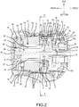
- FIG. 2 is a longitudinal cross sectional view of a rear part of a main body 2 of the driver-drill 1.
- the representative driver-drill 1 has an overall T shape in that a handle 3 extends in a downward (substantially perpendicular) direction from the main body 2, which extends in a rear-front direction.
- a battery pack 5 constitutes a power supply for the driver-drill 1 and is mounted on a mounting part 4, which is formed at a lower end of the handle 3.
- a housing of the main body 2 is formed by assembling (mounting) a front housing 7, which houses (surrounds or encloses, at least substantially) a clutch mechanism and a spindle, onto the front (i.e., the right side in FIG. 1 ) of a tubular main body housing 6, which houses a brushless motor 17 and a planetary gear speed reducing mechanism 72 that are discussed below, via screws 8 screwed in from the front.
- a cap housing 9 is assembled (mounted) on the rear of the main body housing 6 via screws 10 at two locations (upper and lower), that are screwed in from the rear.
- the coupling surfaces between the main body housing 6 and the cap housing 9 form a socket and spigot joint.
- annular protruding parts 6c each of which is formed in a rear surface of the main body housing 6 and includes a screw boss into which the corresponding screw 10 is screwed, are mated against recessed parts 9a, which are formed in a front surface of the cap housing 9.
- a mode changing ring (or action mode changing ring) 11 and a clutch adjusting ring 12 are provided forward of the front housing 7, and a chuck 13, which is mounted on the spindle, is provided forward of the clutch adjusting ring 12.
- the handle 3 is continuous with the main body housing 6, and these are formed by assembling (attaching) left and right half housings 6a, 6b via screws 14.
- Reference number 15 is a trigger that is provided on a switch housed in the handle 3.
- Reference number 16 is a motor forward/reverse changing button (reversing switch lever).
- a (not shown) light preferably provides illumination forward of the chuck 13 and is preferably disposed above the trigger 15.
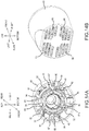
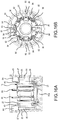
- the brushless motor 17 is housed in a rear part of the main body housing 6 and is an inner rotor type motor that comprises a stator 18 and a rotor 19 rotatably disposed within the stator 18.
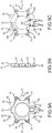
- the stator 18 comprises a tubular stator core 20, which is formed from a plurality of laminated steel sheets, a front insulator 21 and a rear insulator 22, which are respectively provided on the front and rear end surfaces of the stator core 20 in the axial direction, and six coils 23, which are wound on the stator core 20 and through (around) the front and rear insulators 21, 22.
- a sensor circuit board 24 and a short circuiting element 25 are attached to the front insulator 21.
- the stator core 20 comprises six teeth 26 that protrude toward the axial center side (radially inward). Six slots 27 are respectively defined between adjacent pairs of the teeth 26 in the circumferential direction of the stator core 20.
- the front insulator 21 is an annular, integrally-molded article (structure) and has an outer diameter that is the same (or substantially the same) as the outer diameter of the stator core 20.
- Six protruding parts (e.g. hooks) 28 protrude in series toward the axial center side (radially inward) and are located forward of the teeth 26 of the stator core 20.
- the six protruding parts 28 are formed on an inner circumferential side of the front insulator 21.
- six mating parts 29 respectively mate with the slots 27 of the stator core 20 and project from a rear surface side of the front insulator 21.
- Six sets of retaining parts 30 for fusing terminals (connecting terminals) 42 project from the front surface side of the front insulator 21 at positions that respectively correspond with the mating parts 29.
- a pair of projections 31, each projection 31 having a groove 32 is disposed at prescribed spacings such that the grooves 32 oppose one another.
- Screw bosses 33 each of which has a screw hole at its center and extends from a flange part 34 at its base, respectively project between adjacent pairs of the retaining parts 30.
- a pair of recessed parts 35 is formed on both the left and right side parts of the front insulator 21 and serve as positioning parts (discussed further below).
- a pair of triangular first notched parts 36, 36 is formed on the front insulator 21 and also serve as positioning parts (discussed further below).
- One first notched part 36 is defined on the upper side and one first notched part 36 is defined on the lower side of the corresponding recessed parts 35, such that the pair of first notched parts 36 sandwich (surround or are formed in the circumferential direction outwardly of) the corresponding recessed parts 35.
- a quadrangular second notched part 37 is formed at the center of an upper part of the front insulator 21 and also serves as a positioning part (discussed further below).
- the recessed parts 35, the first notched parts 36, and the second notched part 37 are configured or shaped such that their rear surfaces are closed off by the stator core 20 (see e.g., FIG. 7B ).
- the rear insulator 22 is also annular and has the same (or substantially the same) outer diameter as that of the stator core 20.
- Six protruding parts (e.g. hooks) 38 protrude in series toward the axial center side (radially inward) and are located rearward of the teeth 26 of the stator core 20.
- the six protruding parts 38 are formed on an inner circumferential side of the rear insulator 22.
- six mating parts 39 mate with the slots 27 of the stator core 20 and project from a front surface side of the rear insulator 22.
- curved transverse notched parts 40, 40 are formed on the left and right side parts of the rear insulator 22, and chamfer parts 41, 41, which are notched in a straight line, are formed at the centers of the upper and lower parts of the rear insulator 22.
- the fusing terminals (connecting terminals) 42 are respectively retained by the retaining parts 30 of the front insulator 21.
- Each of the fusing terminals 42 is configured (formed) by folding over a strip-shaped metal fitting approximately in half.
- Each of the fusing terminals 42 comprises a first edge part 43, an intermediate region having a portion that is bent into the shape of a protrusion, and a second edge part 44. Both side edges of the second edge part 44 are bent to form wing pieces 45, 45 that are L-shaped in a cross section.
- each of the fusing terminals 42 when the folded side of each of the fusing terminals 42 is inserted into its corresponding retaining part 30, and the wing pieces 45 are mated with the groove parts 32 of the corresponding projections 31, the fusing terminals 42 are concentric (i.e. are disposed along a virtual circle and thus are all equally spaced from a common center point). Furthermore, the fusing terminals 42 are retained such that the respective first edge parts 43 face toward the outer side (radially outward) with an attitude (a longitudinal orientation) that is parallel to the axial direction of the front insulator 21.
- the fusing terminal 42 of the present disclosure may also be called a "thermal crimping terminal” or a “thermal caulking terminal” and generally enables the formation of a secure, robust connection to a lead wire (e.g., winding wire 23a) by applying heat and pressure thereto.
- a method of forming the electrical connection may involve, e.g., applying a sufficiently-large current to the lead wire to heat and thereby delaminate/melt the insulating coating surrounding the metal wire while the lead wire is sandwiched or interposed within the fusing terminal, and applying a crimping pressure to the fusing terminal 42 to thereby thermally crimp or clamp the lead wire to the fusing terminal 42.
- the metal of the lead wire may thereby become fused and/or welded to the fusing terminal 42.
- the coils 23 are respectively wound around the teeth 26 of the stator core 20 and through (around) the respective protruding parts 28, 38 of the front and rear insulators 21, 22.
- just one winding wire i.e. a single continuous wire
- All the fusing terminals 42 are electrically connected to the respective winding wires 23a by being fused (crimped or deformed radially inwardly) such that the winding wires 23a (i.e.
- the sensor circuit board 24 is equipped with three rotation detection devices (not shown), which detect the positions of permanent magnets 63 provided on the rotor 19 and output rotation detection signals.
- the sensor circuit board 24 has an overall doughnut shape and its outer diameter fits within the radially inner sides of the retaining parts 30.
- four projections 46 have through holes 47 that correspond to the screw bosses 33 of the front insulator 21 and extend at the outer circumference of the sensor circuit board 24. Due to the fact that the screw bosses 33 respectively pass through the through holes 47, the projections 46 respectively make contact with the flange parts 34 and are positioned at the front surface of the front insulator 21.
- a leader part 48 for signal lines 49 of the rotation detection devices is provided at the center of a lower part of the sensor circuit board 24, and a heat shrink tube 48a, which includes an adhesive, covers and extends across the leader part 48 and the signal lines 49.
- a heat shrink tube 48a which includes an adhesive, covers and extends across the leader part 48 and the signal lines 49.
- tubular bosses 51 are configured to respectively mate with the screw bosses 33 of the front insulator 21 from the rear.
- the four tubular bosses 51 integrally project at the outer circumference of an annular, resin insulation part 50, whose outer diameter is substantially the same as the outer diameter of the sensor circuit board 24.
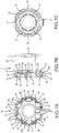
- three sheet metal elements namely, a first sheet metal element 52A, a second sheet metal element 52B, and a third sheet metal element 52C, are insert molded in the insulation part 50.
- the first sheet metal element 52A is formed by radially outwardly bending a pair of short circuiting pieces (tabs or terminals) 53, 53, which are respectively extend from the left and right ends of a (lower) coupling part 54A.
- the coupling part 54A is curved in a U shape and is longitudinally oriented such that its thickness direction is in the radial direction of the stator 18.
- the second sheet metal element 52B comprises a pair of short circuiting pieces (tabs or terminals) 53, 53 on the lower right and the upper left of a coupling part 54B, which is on the left side, is arcuately curved, and is longitudinally oriented such that its thickness direction is the rear-front direction of the stator 18.
- a center portion of the coupling part 54B is offset rearward by bent parts 54d, 54d.
- the third sheet metal element 52C comprises a pair of short circuiting pieces (tabs or terminals) 53, 53 respectively extending from the lower left and the upper right of a coupling part 54C, which is on the right side and is arcuately curved.
- a transversely-oriented semicircular portion of the coupling part 54C is offset rearward from the short circuiting piece 53 on the lower left of the coupling part 54C by a bent part 54d.
- the remaining semicircular portion is curved on the inner side in a longitudinal orientation via a folded part 54e.
- the short circuiting piece 53 on the upper right is bent outward.
- the sheet metal elements 52A-52C each have a semi-circular shape in radial cross-section. As shown in FIG. 11 , these three sheet metal elements 52A-52C are insert molded (embedded) in the insulation part 50 in a state wherein the second sheet metal element 52B is disposed rearward of and on the left side of the first sheet metal element 52A, the third sheet metal element 52C is disposed rearward of and on the right side of the first sheet metal element 52A, and such that the sheet metal elements 52A-52C concentrically overlap without contacting each other. Therefore, the insulation part 50 retains or holds the sheet metal elements 52A-52C in a physically and electrically separated state, i.e. they are electronically isolated from each other.
- the respective pairs of short circuiting pieces 53 (six in total), which are disposed diagonally (diametrically) opposite one another and are electrically interconnected, radially project in correspondence with the fusing terminals 42 retained by the front insulator 21.
- Slits (slots) 55 into which the second edge parts 44 of the fusing terminals 42 can be respectively inserted, are formed at or in the tips (radially outer portions) of the short circuiting pieces 53.
- a connecting piece 56 is located between the short circuiting piece 53 on the lower side of the second sheet metal element 52B and the short circuiting piece 53 on the lower side of the third sheet metal element 52C.
- the connecting piece 56 is formed downward facing at the center of a lower end of the coupling part 54A of the first sheet metal element 52A.
- the U-phase, V-phase, and W-phase power supply lines 57 are respectively spot welded to the rear surface of the short circuiting piece 53 on the lower side of the second sheet metal element 52B, the short circuiting piece 53 on the lower side of the third sheet metal element 52C, and the connecting piece 56. As shown in FIGS.
- two projections 56a, 56a increase the coupling strength to the insulation part 50 and are formed on the left and right of the connecting piece 56.
- Guide ribs 58 partition the respective power supply lines 57, guide the power supply lines 57 downward from the sheet metal elements 52A-52C, retain the power supply lines 57, and are disposed in the up-down direction.
- the guide ribs 58 are provided in parallel, integrally, and erectly to a lower end back surface of the insulation part 50.
- guide projections 50a respectively guide the left and right power supply lines 57 to the short circuiting pieces 53 side, and are formed on an upper side of the guide ribs 58.
- Recessed parts 50b, 50b for positioning are formed on an inner circumferential side of the insulation part 50. As shown in FIG. 10 , a through hole 50c for exposing the connecting piece 56 and thereby increasing its heat dissipating capacity is formed in a lower part of the insulation part 50. Positions P shown in FIGS. 8 , 10 are the locations at which the respective power supply lines 57 are welded.
- the short circuiting element 25 overlaps the sensor circuit board 24 from the front such that the screw bosses 33 of the front insulator 21 are inserted into the bosses 51 and the short circuiting element 25 is affixed thereto by screws 88. Furthermore, the second edge parts 44 of the fusing terminals 42 are respectively inserted into the slits 55 of the corresponding short circuiting pieces 53.
- the sheet metal elements 52A-52C are not exposed at the rear surface of the insulation part 50 and therefore do not contact the sensor circuit board 24 due to the intervening resin of the insulating part 50.
- the center hole of the sensor circuit board 24 is preferably smaller than the center hole of the short circuiting element 25 in the present embodiment.
- each of the fusing terminals 42 is electrically connected to one of the winding wires 23a between circumferentially-adjacent coils sequentially wound around the stator core 20.
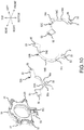
- respective pairs of fusing terminals 42 that are diagonally (diametrically) opposite one another are electrically interconnected by the first through third sheet metal elements 52A-52C, thereby forming a parallel-winding delta connection.
- Reference symbol S is the start of the winding (i.e. the single continuous winding wire), and reference symbol E is the end of the same winding.
- the short circuiting element 25 is not a hindrance during the manufacturing step of winding the respective coils 23 on the teeth 26 of the stator core 20 and on the front and rear insulators 21, 22.
- the fusing terminals 42 are formed with a sufficient height (axial length) to provide a stable and durable connection (joining).
- the sensor circuit board 24 and the short circuiting element 25 fit within the height (axial length) dimension of the fusing terminals 42, and consequently the entire (axial) length of the brushless motor 17 is kept to a minimum even though the short circuiting element 25, etc. are used (installed).
- all the elements fit within the outer diameter of the stator core 20. Consequently, the outer diameter of the product also does not increase, and the product is therefore compact.
- the thus-assembled stator 18 is housed (supported) while being positioned in the axial direction and in the circumferential direction in the following manner.
- the outer circumference of the stator core 20 is held by support ribs 59, which project in the circumferential directions from the inner surfaces of the half housings 6a, 6b of the main body housing 6.
- the outer circumference of the stator core 20 is also held by projections 60, which project from the inner surface of the half housing 6a and respectively mate with the recessed parts 35, which are formed (defined) in the side surface of the front insulator 21.
- the assembly is done while ensuring that the planar surfaces of the chamfer parts 41 do not contact the support ribs 59, which makes it easy to perform the assembly in the desired orientation.
- the recessed part at the center of each of the projections 60 has a reduced thickness; therefore, if the projections 60 are formed also in the half housing 6b, the stator 18 can be more suitably held.
- the rotor 19 comprises: a rotary shaft 61, which is located at the axial center; a tubular rotor core 62, which is disposed around the rotary shaft 61; and the permanent magnets 63, which are disposed on the outer side of the rotor core 62 and have polarities that alternate in the circumferential direction of the cylindrical shape.
- the rear end of the rotary shaft 61 is pivotally supported by a bearing 64, which is held by the cap housing 9, and a centrifugal fan 65 is attached at a forward position thereof.
- a center part of the centrifugal fan 65 bulges forward so as to form a cone shape, and the bearing 64 has a shape that projects rearward therefrom. Due to this design, the distance between the cap housing 9 and the centrifugal fan 65 becomes shorter (can be decreased), resulting in a shortening of the overall length of the driver-drill 1.
- Reference numbers 66 are air suction ports ( FIG. 1 ) that are respectively formed on the left and right side surfaces of the main body housing 6, and reference numbers 67 are exhaust ports ( FIGS. 1 , 2 ) that are respectively formed on the left and right side surfaces of the cap housing 9.
- a gear case 68 houses (surrounds) the planetary gear speed reducing mechanism 72 and is provided forward of the brushless motor 17.
- the front end of the rotary shaft 61 is inserted through a cap 69, which closes up a rear end of the gear case 68, and is pivotally supported by a bearing 70, which is held by the cap 69.
- a pinion 71 is fastened to the front end of the rotary shaft 61.
- the planetary gear speed reducing mechanism 72 has a well-known structure.
- a plurality of carriers 75 respectively support a plurality of planetary gears 74, 74 that revolve inside an internal gear 73, and are provided in parallel in the axial direction.
- a second stage internal gear (denoted as reference number 73A in order to distinguish such) is provided such that it can move frontward and rearward in the axial directions between an advanced position and a retracted position. In the advanced position, the second stage internal gear is fixed inside the gear case 68 and the second stage planetary gears 74 are caused to revolve.
- a speed changing ring 77 is coupled to the internal gear 73A via pins 76.
- a projection 78 at an upper end of the speed changing ring 77 is coupled to a speed changing button (speed changing lever) 80 via front and rear coil springs 79, 79.
- a not-shown microcontroller of a controller which is housed in the lower part of the handle 3, determines the rotational state of the rotor 19 by obtaining the rotation detection signals, which indicate the positions of the permanent magnets 63 of the rotor 19, output from the rotation detection devices of the sensor circuit board 24, and controls the ON/OFF state of each of the switching devices in accordance with the determined rotational state. Then, the rotor 19 is rotated by sequentially supplying electric current to each of the (diametrically-opposite pairs of) coils 23 of the stator 18.
- the coils 23 of the present brushless motor 17 are in the parallelly wound state, the electrical resistance of the winding is reduced and a large current can be supplied.
- This parallelly wound state can be achieved by using the short circuiting element 25, which makes it possible to save space. That is, as shown in FIG. 2 , because the relatively-thin short circuiting element 25 is disposed within the inner sides of the retaining parts 30 and is assembled such that the short circuiting element 25 does not protrude forward of the tips of the projections 31 of the retaining parts 30, the space forward of the sensor circuit board 24 can be used effectively (efficiently) to install the short circuiting element 25, thereby making the compact size maintainable.
- the six coils 23 are wound with a single winding wire (i.e. a single wire having no breaks or interruptions in it), all the coils 23 can be completely wound in a single manufacturing step, and crossover wires for connecting coils wound around the teeth that are diametrically positioned (opposed) become unnecessary. The absence of crossover wires also leads to making the product compact.
- the sensor circuit board 24 is provided on one end side of the brushless motor 17 and the power is supplied to the coils 23 from the same side, it becomes possible to supply a large current while maintaining the compact size.
- the sensor circuit board 24 and the short circuiting element 25 are arranged in order (successively) on the one end side of the stator 18, the sensitivity of the sensors is satisfactory.
- a structure is utilized in which the brushless motor 17 is housed in the main body housing 6, which is formed of the two half housings 6a, 6b.
- the brushless motor 17 is housed in a tubular housing that is used in a circular saw or the like, then, in the state wherein the stator 18 of the brushless motor 17 is oriented rearward, the short circuiting element 25 side being rearward, a bottom part of a tubular housing 81 is provided with four L-shaped receiving ribs 82, whose tips mate with the four first notched parts 36 of the front insulator 21 of the stator 18 and which make contact with the end surface of the stator core 20.
- a plate-shaped rotation stopping rib 83 has a tip that mates with the second notched part 37 of the front insulator 21 and it makes contact with the end surface of the stator core 20. Furthermore, in front of these, pairs of longitudinal ribs 84 make contact with a circumferential surface of the stator 18 and are provided with up-down and left-right symmetry.
- Reference number 81a is a housing recessed part of a bearing.
- screw bosses 85 are provided with heights are such that the screw bosses 85, 85 are flush with the end surface of the stator core 20 in the housed state.
- the screw bosses 85 are respectively provided between the left longitudinal ribs 84, 84 and between the right longitudinal ribs 84, 84. Furthermore, by tightening the screws 86 from the front through the washers 87 into the screw bosses 85, it is possible to mate the washers 87 against the transverse notched parts 40 of the rear insulator 22 and thereby to press the end surface of the stator core 20 from the front.
- the stator 18 is prevented from moving rearward by the receiving ribs 82 and is prevented from moving in the circumferential direction by the rotation stopping rib 83. Moreover, the stator 18 is centered inside the tubular housing 81 by the longitudinal ribs 84. Furthermore, forward movement is prevented by the screws 86 and the washers 87.
- a guide part 21a projects from the front insulator 21, when the stator 18 is pressed in, the stator 18 can be smoothly set to the target position if the guide part 21a is pressed in such that it fits between the longitudinal ribs 84, 84, as shown in FIG. 15A . After being pressed in, it is also positioned in the circumferential direction.
- stator 18 can be positioned simply by using the notched parts 36, 37, 40 provided in the front and rear insulators 21, 22, and it also becomes possible to standardize the front and rear insulators 21, 22.
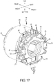
- the signal lines 49 of the sensor circuit board 24 extend from the same side (i.e., the lower side) as the power supply lines 57 of the short circuiting element 25 (see FIG. 7B ), the signal lines 49 may extend from the upper side by changing (rotating) the phase (orientation) of the sensor circuit board 24 by 180°, which embodiment is exemplified by the stator 18 shown in FIG. 17 (compare the orientation of the sensor circuit boards in FIGS. 3 and 17 ).
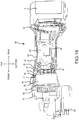
- a grinder 90 as shown in FIG.
- reference number 92 is a controller
- reference number 93 is a switch that is connected to the controller 92 via a lead wire 94
- reference number 95 is a slide button that turns the switch 93 ON and OFF via a linking bar 96
- reference number 97 is a front housing having a downwardly-protruding spindle 98.
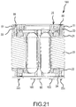
- the sensor circuit board 24 can also be provided on the side of the stator core 20 opposite the short circuiting element 25. That is, in an alternative embodiment of a stator 18A as shown in FIGS. 19-21 , the sensor circuit board 24 is provided on the rear surface of the rear insulator 22, and therefore transverse notched parts 22a and a chamfer part 22b are formed, in accordance with the transverse notched parts 40 and the chamfer part 41 provided on the rear insulator 22, on the outer circumference of the sensor circuit board 24, which makes it possible to also assemble the stator 18A in a tubular housing. Reference numbers 99 are screws, and reference numbers 100 are rotation detection devices (Hall-effect ICs).
- the positions of permanent magnets provided on the centrifugal fan 65 are detected by the rotation detection devices 100.
- the short circuiting element 25 is assembled in the front insulator 21 without transiting the sensor circuit board 24.
- the short circuiting element 25 mates and seats the recessed parts on the rear surface sides of the bosses 51 to and in the upper surfaces of the screw bosses 33 of the front insulator 21, the position of the short circuiting element 25 does not change even without the sensor circuit board 24.
- the short circuiting element 25 is positioned by the mating of the recesses and protrusions between the screw bosses 33 and the bosses 51.
- a plurality of projections 22c integrally project from the rear surface of the rear insulator 22, and the sensor circuit board 24 is retained by inserting the projections in through holes provided in the sensor circuit board 24 and then thermally deforming the projections.
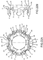
- FIGS. 22A and B show a modified example of the front insulator 21, and FIGS. 23A and B show a modified example of the rear insulator 22.
- recessed grooves 28a are formed in the front insulator 21, in directions orthogonal to the protruding parts 28, on the front surface sides of the bases of the protruding parts 28.
- relief parts 28b, 28b which are recessed in the radial directions, are formed on both sides in the circumferential direction of the bases of the protruding parts 28.
- FIGS. 22A and B show a modified example of the front insulator 21
- FIGS. 23A and B show a modified example of the rear insulator 22.
- recessed grooves 28a are formed in the front insulator 21, in directions orthogonal to the protruding parts 28, on the front surface sides of the bases of the protruding parts 28.
- relief parts 28b, 28b which are recessed in the radial directions, are formed on both sides in the circumferential direction of the bases
- recessed grooves 38a are also formed in the rear insulator 22, in directions orthogonal to the protruding parts 38, on the rear surface sides of the bases of the protruding parts 38.
- relief parts 38b, 38b which are recessed in the radial directions, are formed on both sides in the circumferential direction of the bases of the protruding parts 38.
- Each one of the winding wires of the coils 23 in the teeth 26 starts its winding by being fitted in the recessed grooves 28a, 38a, such that the coil of the first winding is held exactly at the base of one of the teeth, and the coils of the second and subsequent windings are successively wound in series around the respective bases of the circumferentially adjacent teeth.
- a nozzle for winding the coils 23 easily passes through the relief parts 28b, 38b.
- hollow parts 38c for smoothly winding the coils 23 are also formed on both sides of the bases of the protruding parts 38 on the inner circumferential surface of the rear insulator 22.
- transverse notched parts 40, 40 are located between protruding parts 38, 38, and because protruding parts 38 are located in the portions of the widths across the respective flats of the chamfer parts 41, 41, the outer circumference of the rear insulator 22 is not enlarged.
- the short circuiting means comprises the short circuiting element(s) and the fusing terminals; however, it is also possible, for example: to omit the fusing terminals and to short circuit (electrically connect or shunt) the winding wires with just the short circuiting element(s); conversely, it is also possible to omit the short circuiting element(s) and to interconnect the fusing terminals with lead wires, etc.
- the power tool is not limited to a type that drives a tool accessory, such as a driver-drill, a circular saw, or a grinder
- a tool accessory such as a driver-drill, a circular saw, or a grinder
- the present invention can also be adapted, for example and without limitation, to vacuum cleaners and, furthermore, to gardening tools such as a blower.
- the present invention can also be adapted to power tools that use a sensor-less brushless motor and therefore have no sensor circuit board.
- the term "short circuit” is generally intended to mean a low resistance electrical connection such as a metal plate material or metal wire material.
- no additional resistive element e.g., a ceramic resistor
- the short circuit acts, e.g., as a shunt, i.e. one or more small or low resistance elements may be added to the short circuit electrical path, if appropriate for the particular design.
- metal sheet (plate) elements were used in the above-described representative embodiments, the short circuit electrical connections may also be in the form of a wire (i.e. round or oval shapes) as long as the wire has a sufficient diameter (thickness) to handle the rated current that is expected to flow through it.
Description
- The present application claims priority to Japanese patent application serial number
2013-188528 filed on September 11, 2013 - The present invention relates to a power tool, such as a driver-drill, that comprises a motor serving as its drive source.
- As disclosed, e.g., in
US 2011/0043057 A1 (and its family memberJP 2011-45201 A - For example, an electric motor for a light load model typically has a structure wherein the main current flows to a sensor circuit board via a solderable wire. On the other hand, in an electric motor for a heavy load model, lead wires (i.e., power supply wires) are typically directly connected to more robust fusing terminals (connecting terminals) due to the higher current that flows therethrough.
- Although electric motors for light (low) load power tools may have a small size and thus be space saving, generally speaking such electric motors are not capable of drawing (or being driven by) a large current, thereby limiting their applicability. In contrast, while electric motors for heavy (high) load power tools are designed to draw (or be driven by) a large current, such electric motors are generally larger than light load electric motors and consequently are not suitable for making a compact power tool.
-
US 2007/0296292 A1 discloses an electric motor having a rotor and a stator, which stator is equipped with poles, each pole having an individual winding. Arranged approximately concentrically with a rotation axis of the rotor is an arrangement having electrical connection elements equipped with mounting elements to each of which an associated end of an individual winding is mechanically and electrically connected. A connection arrangement has a plurality of conductors each of which is connected, by means of a welded connection, to the connection elements of the stator. -
WO 2011/155327 A1 discloses a coil comprising a first winding end, which is located on the outside in the radial direction at one end side in the axial direction of a stator, and a second winding end which is located on the inside in the radial direction. The first winding end is connected to the second winding end of the coil which is adjacent within the in-phase coil via spanning sections. -
WO 2009/145205 A1 discloses an electrical power tool which includes a housing, a brushless direct-current type motor and a drive circuit that supplies drive power to the motor. The drive circuit includes plural switching elements and is mounted on a board provided on the rear end side of the motor. -
WO 03/066262 A2 -
EP 2 139 098 A2 -
CN 102 403 815 A discloses a connection structure of a motor stator and a stator circuit board. - Accordingly, it is an object of the present invention to overcome one or more problems of the known art and to, e.g., provide a compact power tool that can utilize a relatively small-sized motor capable of drawing a large current.
- This object is achieved by the invention of claim 1.
- Further developments of the invention are recited in the dependent claims.
- In a first aspect of the present teachings, a power tool preferably comprises a motor that includes a stator and a rotor. A plurality of coils (e.g., at least six) are wound on the stator such that the coils are wound through respective insulators located at the front and rear in an axial direction of the stator. The power tool further comprises a short circuiting means that short circuits diagonally-positioned (diametrically-opposite) pairs of winding wires between the coils, of which there are at least six.
- In a second aspect of the present teachings, all of the coils are preferably wound with one winding wire (a single continuous wire).
- In addition or in the alternative to the second aspect, the short circuiting means preferably comprises: a plurality of sheet metal elements, which electrically interconnect the pairs of winding wires between the coils (the winding wires that are diametrically opposite of each other), and an insulation part, which is made of resin and retains the sheet metal elements.
- In addition or in the alternative to the first and/or the second aspect, the short circuiting means preferably is lead wires that electrically interconnect the pairs of winding wires between the coils.
- In addition or in the alternative to any preceding aspect, a sensor circuit board, which comprises a rotation detection device that detects positions of permanent magnets provided on the rotor, is preferably provided between the insulator and the short circuiting means.
- The sensor circuit board is preferably mountable at a different phase.
- In another aspect of the present teachings, a power tool preferably comprises a motor that includes a stator and a rotor. A plurality of coils are wound on the stator such that the coils are wound through respective insulators located at the front and rear in an axial direction of the stator. A housing that houses the motor is formed by combining a pair of half housings. The stator is provided with at least one positioning part that engages with respective inner surfaces of the half housings.
- In another aspect of the present teachings, a power tool preferably comprises a motor that includes a stator and a rotor. A plurality of coils are wound on the stator such that the coils are wound through respective insulators located at the front and rear in an axial direction of the stator. A housing that houses the motor is a tubular housing. The stator is provided with at least one positioning part that engages with an inner surface of the tubular housing.
- Either of the above-noted positioning parts may be provided on the insulator(s).
- According to the present teachings, a compact power tool can be achieved by using a motor that can draw a large current, even though it is small sized and space saving.
-
-
FIG. 1 is an overall view of a driver-drill according to the present teachings. -
FIG. 2 is a longitudinal cross sectional view of a main body rear part of the driver-drill. -
FIG. 3 is a perspective, side view of a representative brushless motor. -
FIG. 4 is a perspective, rear view of the brushless motor. -
FIG. 5 is an exploded perspective view of the brushless motor. -
FIG. 6 provides explanatory diagrams of a representative sensor circuit board, whereinFIG. 6A is a front view thereof, andFIG. 6B is a cross sectional view taken along the B-B line inFIG. 6A . -
FIG. 7 provides explanatory diagrams of the brushless motor, whereinFIG. 7A is a front view thereof,FIG. 7B is a side view thereof, andFIG. 7C is a rear view thereof. -
FIG. 8A is a perspective, front view of a representative short circuiting element, andFIG. 8B is a perspective, rear view of the short circuiting element. -
FIG. 9 provides explanatory diagrams of the short circuiting element, whereinFIG. 9A is a front view thereof,FIG. 9B is a side view thereof, andFIG. 9C is a rear view thereof. -
FIG. 10 is an exploded perspective view of the short circuiting element. -
FIG. 11 is an explanatory diagram that shows the arrangement of sheet metal elements of the short circuiting element. -
FIG. 12 shows a representative wiring diagram for the coils. -
FIG. 13 is a cross sectional view taken along the A-A line inFIG. 2 . -
FIG. 14A is a perspective, front view of a representative tubular housing, andFIG. 14B is a perspective, rear view of the tubular housing. -
FIG. 15A is a front view of the tubular housing, andFIG. 15B is a cross sectional view taken along the C-C line inFIG. 15A . -
FIG. 16A is a cross sectional view taken along the D-D line inFIG. 15A , andFIG. 16B is a cross sectional view taken along the E-E line inFIG.15B . -
FIG. 17 is a perspective view of another brushless motor, wherein the orientation of the sensor circuit board has been changed (rotated by 180° as compared to the orientation shown inFIG. 3 ). -
FIG. 18 is a longitudinal cross sectional view of a representative grinder according to the present teachings. -
FIG. 19 is a perspective view of a stator, wherein the attachment position of the sensor circuit board has been changed (as compared to the attachment position shown inFIG. 3 ). -
FIG. 20 shows explanatory diagrams of the stator in which the attachment position of the sensor circuit board has been changed, whereinFIG. 20A is a rear view thereof,FIG. 20B is a side view thereof, andFIG. 20C is a front view thereof. -
FIG. 21 is a cross sectional view taken along the F-F line inFIG. 20C . -
FIG. 22 shows explanatory diagrams of a modified example of a front insulator, whereinFIG. 22A is a front view thereof, andFIG. 22B is a cross sectional view taken along the G-G line inFIG. 22A . -
FIG. 23 shows explanatory diagrams of a modified example of a rear insulator, whereinFIG. 23A is a front view thereof, andFIG. 23B is a cross sectional view taken along the H-H line inFIG. 23A . -
FIG. 1 is an overall view of a driver-drill 1, which serves one representative, non-limiting example of a power tool according to the present teachings.FIG. 2 is a longitudinal cross sectional view of a rear part of amain body 2 of the driver-drill 1. The representative driver-drill 1 has an overall T shape in that ahandle 3 extends in a downward (substantially perpendicular) direction from themain body 2, which extends in a rear-front direction. Furthermore, abattery pack 5 constitutes a power supply for the driver-drill 1 and is mounted on a mountingpart 4, which is formed at a lower end of thehandle 3. - A housing of the
main body 2 is formed by assembling (mounting) afront housing 7, which houses (surrounds or encloses, at least substantially) a clutch mechanism and a spindle, onto the front (i.e., the right side inFIG. 1 ) of a tubularmain body housing 6, which houses abrushless motor 17 and a planetary gearspeed reducing mechanism 72 that are discussed below, viascrews 8 screwed in from the front. Then, acap housing 9 is assembled (mounted) on the rear of themain body housing 6 viascrews 10 at two locations (upper and lower), that are screwed in from the rear. The coupling surfaces between themain body housing 6 and thecap housing 9 form a socket and spigot joint. That is, annular protrudingparts 6c, each of which is formed in a rear surface of themain body housing 6 and includes a screw boss into which thecorresponding screw 10 is screwed, are mated against recessedparts 9a, which are formed in a front surface of thecap housing 9. A mode changing ring (or action mode changing ring) 11 and aclutch adjusting ring 12 are provided forward of thefront housing 7, and achuck 13, which is mounted on the spindle, is provided forward of theclutch adjusting ring 12. Furthermore, thehandle 3 is continuous with themain body housing 6, and these are formed by assembling (attaching) left andright half housings Reference number 15 is a trigger that is provided on a switch housed in thehandle 3.Reference number 16 is a motor forward/reverse changing button (reversing switch lever). A (not shown) light preferably provides illumination forward of thechuck 13 and is preferably disposed above thetrigger 15. - The
brushless motor 17 is housed in a rear part of themain body housing 6 and is an inner rotor type motor that comprises astator 18 and arotor 19 rotatably disposed within thestator 18. As shown inFIGS. 3-5 , thestator 18 comprises atubular stator core 20, which is formed from a plurality of laminated steel sheets, afront insulator 21 and arear insulator 22, which are respectively provided on the front and rear end surfaces of thestator core 20 in the axial direction, and sixcoils 23, which are wound on thestator core 20 and through (around) the front andrear insulators sensor circuit board 24 and ashort circuiting element 25 are attached to thefront insulator 21. - The
stator core 20 comprises sixteeth 26 that protrude toward the axial center side (radially inward). Sixslots 27 are respectively defined between adjacent pairs of theteeth 26 in the circumferential direction of thestator core 20. - The
front insulator 21 is an annular, integrally-molded article (structure) and has an outer diameter that is the same (or substantially the same) as the outer diameter of thestator core 20. Six protruding parts (e.g. hooks) 28 protrude in series toward the axial center side (radially inward) and are located forward of theteeth 26 of thestator core 20. The six protrudingparts 28 are formed on an inner circumferential side of thefront insulator 21. In addition, sixmating parts 29 respectively mate with theslots 27 of thestator core 20 and project from a rear surface side of thefront insulator 21. Six sets of retainingparts 30 for fusing terminals (connecting terminals) 42, which are discussed below, project from the front surface side of thefront insulator 21 at positions that respectively correspond with themating parts 29. In each of the retainingparts 30, a pair ofprojections 31, eachprojection 31 having agroove 32, is disposed at prescribed spacings such that thegrooves 32 oppose one another.Screw bosses 33, each of which has a screw hole at its center and extends from aflange part 34 at its base, respectively project between adjacent pairs of the retainingparts 30. - Furthermore, as is shown in
FIG. 3-5 and7 , a pair of recessedparts 35 is formed on both the left and right side parts of thefront insulator 21 and serve as positioning parts (discussed further below). A pair of triangular first notchedparts front insulator 21 and also serve as positioning parts (discussed further below). One first notchedpart 36 is defined on the upper side and one first notchedpart 36 is defined on the lower side of the corresponding recessedparts 35, such that the pair of first notchedparts 36 sandwich (surround or are formed in the circumferential direction outwardly of) the corresponding recessedparts 35. Furthermore, a quadrangular second notchedpart 37 is formed at the center of an upper part of thefront insulator 21 and also serves as a positioning part (discussed further below). The recessedparts 35, the first notchedparts 36, and the second notchedpart 37 are configured or shaped such that their rear surfaces are closed off by the stator core 20 (see e.g.,FIG. 7B ). - The
rear insulator 22 is also annular and has the same (or substantially the same) outer diameter as that of thestator core 20. Six protruding parts (e.g. hooks) 38 protrude in series toward the axial center side (radially inward) and are located rearward of theteeth 26 of thestator core 20. The six protrudingparts 38 are formed on an inner circumferential side of therear insulator 22. In addition, sixmating parts 39 mate with theslots 27 of thestator core 20 and project from a front surface side of therear insulator 22. Furthermore, curved transverse notchedparts rear insulator 22, andchamfer parts rear insulator 22. - Furthermore, the fusing terminals (connecting terminals) 42 are respectively retained by the retaining
parts 30 of thefront insulator 21. Each of thefusing terminals 42 is configured (formed) by folding over a strip-shaped metal fitting approximately in half. Each of thefusing terminals 42 comprises afirst edge part 43, an intermediate region having a portion that is bent into the shape of a protrusion, and asecond edge part 44. Both side edges of thesecond edge part 44 are bent to formwing pieces fusing terminals 42 is inserted into its corresponding retainingpart 30, and thewing pieces 45 are mated with thegroove parts 32 of the correspondingprojections 31, thefusing terminals 42 are concentric (i.e. are disposed along a virtual circle and thus are all equally spaced from a common center point). Furthermore, thefusing terminals 42 are retained such that the respectivefirst edge parts 43 face toward the outer side (radially outward) with an attitude (a longitudinal orientation) that is parallel to the axial direction of thefront insulator 21. - The fusing
terminal 42 of the present disclosure may also be called a "thermal crimping terminal" or a "thermal caulking terminal" and generally enables the formation of a secure, robust connection to a lead wire (e.g., windingwire 23a) by applying heat and pressure thereto. For example, a method of forming the electrical connection may involve, e.g., applying a sufficiently-large current to the lead wire to heat and thereby delaminate/melt the insulating coating surrounding the metal wire while the lead wire is sandwiched or interposed within the fusing terminal, and applying a crimping pressure to the fusingterminal 42 to thereby thermally crimp or clamp the lead wire to the fusingterminal 42. The metal of the lead wire may thereby become fused and/or welded to the fusingterminal 42. - In the present embodiment, the
coils 23 are respectively wound around theteeth 26 of thestator core 20 and through (around) the respective protrudingparts rear insulators respective teeth 26 that are adjacent in the circumferential direction. All thefusing terminals 42 are electrically connected to the respective windingwires 23a by being fused (crimped or deformed radially inwardly) such that the windingwires 23a (i.e. portions of the single continuous winding wire that respectively provide electrical connections between circumferentially-adjacent pairs of the coils 23) loop around the outer sides of the retainingparts 30 and are respectively sandwiched (crimped or clamped) in thefusing terminals 42, as can be best seen inFIG. 3 . - Referring now to
FIG. 2 , thesensor circuit board 24 is equipped with three rotation detection devices (not shown), which detect the positions ofpermanent magnets 63 provided on therotor 19 and output rotation detection signals. As can be seen inFIG. 5 , thesensor circuit board 24 has an overall doughnut shape and its outer diameter fits within the radially inner sides of the retainingparts 30. Furthermore, as is also shown inFIG. 6 , fourprojections 46 have throughholes 47 that correspond to thescrew bosses 33 of thefront insulator 21 and extend at the outer circumference of thesensor circuit board 24. Due to the fact that thescrew bosses 33 respectively pass through the throughholes 47, theprojections 46 respectively make contact with theflange parts 34 and are positioned at the front surface of thefront insulator 21. Aleader part 48 forsignal lines 49 of the rotation detection devices is provided at the center of a lower part of thesensor circuit board 24, and aheat shrink tube 48a, which includes an adhesive, covers and extends across theleader part 48 and the signal lines 49. Using the heat shrinktube 48a makes it possible to simultaneously waterproof and prevent a break in the signal lines 49. - Further explanation of the representative
short circuiting element 25 will now be provided with reference toFIGS. 8 and9 . As shown therein, fourtubular bosses 51 are configured to respectively mate with thescrew bosses 33 of thefront insulator 21 from the rear. The fourtubular bosses 51 integrally project at the outer circumference of an annular,resin insulation part 50, whose outer diameter is substantially the same as the outer diameter of thesensor circuit board 24. In addition, as can also be seen inFIG. 10 , three sheet metal elements, namely, a firstsheet metal element 52A, a secondsheet metal element 52B, and a thirdsheet metal element 52C, are insert molded in theinsulation part 50. The firstsheet metal element 52A is formed by radially outwardly bending a pair of short circuiting pieces (tabs or terminals) 53, 53, which are respectively extend from the left and right ends of a (lower)coupling part 54A. Thecoupling part 54A is curved in a U shape and is longitudinally oriented such that its thickness direction is in the radial direction of thestator 18. The secondsheet metal element 52B comprises a pair of short circuiting pieces (tabs or terminals) 53, 53 on the lower right and the upper left of acoupling part 54B, which is on the left side, is arcuately curved, and is longitudinally oriented such that its thickness direction is the rear-front direction of thestator 18. A center portion of thecoupling part 54B is offset rearward bybent parts sheet metal element 52C comprises a pair of short circuiting pieces (tabs or terminals) 53, 53 respectively extending from the lower left and the upper right of acoupling part 54C, which is on the right side and is arcuately curved. A transversely-oriented semicircular portion of thecoupling part 54C is offset rearward from theshort circuiting piece 53 on the lower left of thecoupling part 54C by abent part 54d. The remaining semicircular portion is curved on the inner side in a longitudinal orientation via a foldedpart 54e. Theshort circuiting piece 53 on the upper right is bent outward. Thesheet metal elements 52A-52C each have a semi-circular shape in radial cross-section. As shown inFIG. 11 , these threesheet metal elements 52A-52C are insert molded (embedded) in theinsulation part 50 in a state wherein the secondsheet metal element 52B is disposed rearward of and on the left side of the firstsheet metal element 52A, the thirdsheet metal element 52C is disposed rearward of and on the right side of the firstsheet metal element 52A, and such that thesheet metal elements 52A-52C concentrically overlap without contacting each other. Therefore, theinsulation part 50 retains or holds thesheet metal elements 52A-52C in a physically and electrically separated state, i.e. they are electronically isolated from each other. - Therefore, at the outer circumference of the
insulation part 50, the respective pairs of short circuiting pieces 53 (six in total), which are disposed diagonally (diametrically) opposite one another and are electrically interconnected, radially project in correspondence with thefusing terminals 42 retained by thefront insulator 21. Slits (slots) 55, into which thesecond edge parts 44 of thefusing terminals 42 can be respectively inserted, are formed at or in the tips (radially outer portions) of theshort circuiting pieces 53. - Furthermore, referring to
FIG. 11 , a connectingpiece 56 is located between theshort circuiting piece 53 on the lower side of the secondsheet metal element 52B and theshort circuiting piece 53 on the lower side of the thirdsheet metal element 52C. The connectingpiece 56 is formed downward facing at the center of a lower end of thecoupling part 54A of the firstsheet metal element 52A. The U-phase, V-phase, and W-phasepower supply lines 57 are respectively spot welded to the rear surface of theshort circuiting piece 53 on the lower side of the secondsheet metal element 52B, theshort circuiting piece 53 on the lower side of the thirdsheet metal element 52C, and the connectingpiece 56. As shown inFIGS. 10 and11 , twoprojections insulation part 50 and are formed on the left and right of the connectingpiece 56.Guide ribs 58 partition the respectivepower supply lines 57, guide thepower supply lines 57 downward from thesheet metal elements 52A-52C, retain thepower supply lines 57, and are disposed in the up-down direction. Theguide ribs 58 are provided in parallel, integrally, and erectly to a lower end back surface of theinsulation part 50. In addition, as shown in the rear surface view of theinsulation part 50 inFIG. 9C , guideprojections 50a respectively guide the left and rightpower supply lines 57 to theshort circuiting pieces 53 side, and are formed on an upper side of theguide ribs 58. Recessedparts insulation part 50. As shown inFIG. 10 , a throughhole 50c for exposing the connectingpiece 56 and thereby increasing its heat dissipating capacity is formed in a lower part of theinsulation part 50. Positions P shown inFIGS. 8 ,10 are the locations at which the respectivepower supply lines 57 are welded. - In the assembled state, the
short circuiting element 25 overlaps thesensor circuit board 24 from the front such that thescrew bosses 33 of thefront insulator 21 are inserted into thebosses 51 and theshort circuiting element 25 is affixed thereto byscrews 88. Furthermore, thesecond edge parts 44 of thefusing terminals 42 are respectively inserted into theslits 55 of the correspondingshort circuiting pieces 53. In the present embodiment, thesheet metal elements 52A-52C are not exposed at the rear surface of theinsulation part 50 and therefore do not contact thesensor circuit board 24 due to the intervening resin of the insulatingpart 50. Furthermore, the center hole of thesensor circuit board 24 is preferably smaller than the center hole of theshort circuiting element 25 in the present embodiment. - If the
fusing terminals 42 and theshort circuiting pieces 53 are soldered in this state, then the respective pairs of fusingterminals sheet metal elements 52A-52C. Thus, as shown in the wiring diagram ofFIG. 12 , each of thefusing terminals 42 is electrically connected to one of the windingwires 23a between circumferentially-adjacent coils sequentially wound around thestator core 20. Further, respective pairs of fusingterminals 42 that are diagonally (diametrically) opposite one another are electrically interconnected by the first through thirdsheet metal elements 52A-52C, thereby forming a parallel-winding delta connection. Reference symbol S is the start of the winding (i.e. the single continuous winding wire), and reference symbol E is the end of the same winding. - In the present embodiment, because the
fusing terminals 42 and theshort circuiting element 25 are separate bodies, and theshort circuiting pieces 53 of theshort circuiting element 25 are soldered onto thefusing terminals 42 after thecoils 23 have been wound, theshort circuiting element 25 is not a hindrance during the manufacturing step of winding the respective coils 23 on theteeth 26 of thestator core 20 and on the front andrear insulators - In addition, the
fusing terminals 42 are formed with a sufficient height (axial length) to provide a stable and durable connection (joining). However, as shown in e.g.,FIG. 2 ,FIG. 7(B) , thesensor circuit board 24 and theshort circuiting element 25 fit within the height (axial length) dimension of thefusing terminals 42, and consequently the entire (axial) length of thebrushless motor 17 is kept to a minimum even though theshort circuiting element 25, etc. are used (installed). Furthermore, except for the signal lines, the power supply lines, and the like, all the elements fit within the outer diameter of thestator core 20. Consequently, the outer diameter of the product also does not increase, and the product is therefore compact. - As shown in
FIG. 13 , the thus-assembledstator 18 is housed (supported) while being positioned in the axial direction and in the circumferential direction in the following manner. The outer circumference of thestator core 20 is held bysupport ribs 59, which project in the circumferential directions from the inner surfaces of thehalf housings main body housing 6. In addition, the outer circumference of thestator core 20 is also held byprojections 60, which project from the inner surface of thehalf housing 6a and respectively mate with the recessedparts 35, which are formed (defined) in the side surface of thefront insulator 21. Furthermore, when thestator 18 is to be housed in thehalf housings chamfer parts 41 do not contact thesupport ribs 59, which makes it easy to perform the assembly in the desired orientation. The recessed part at the center of each of theprojections 60 has a reduced thickness; therefore, if theprojections 60 are formed also in thehalf housing 6b, thestator 18 can be more suitably held. - Moreover, as shown in
FIG. 2 , therotor 19 comprises: arotary shaft 61, which is located at the axial center; atubular rotor core 62, which is disposed around therotary shaft 61; and thepermanent magnets 63, which are disposed on the outer side of therotor core 62 and have polarities that alternate in the circumferential direction of the cylindrical shape. - The rear end of the
rotary shaft 61 is pivotally supported by abearing 64, which is held by thecap housing 9, and acentrifugal fan 65 is attached at a forward position thereof. In the present embodiment, a center part of thecentrifugal fan 65 bulges forward so as to form a cone shape, and thebearing 64 has a shape that projects rearward therefrom. Due to this design, the distance between thecap housing 9 and thecentrifugal fan 65 becomes shorter (can be decreased), resulting in a shortening of the overall length of the driver-drill 1.Reference numbers 66 are air suction ports (FIG. 1 ) that are respectively formed on the left and right side surfaces of themain body housing 6, andreference numbers 67 are exhaust ports (FIGS. 1 ,2 ) that are respectively formed on the left and right side surfaces of thecap housing 9. - In addition, as shown in
FIG. 2 , agear case 68 houses (surrounds) the planetary gearspeed reducing mechanism 72 and is provided forward of thebrushless motor 17. The front end of therotary shaft 61 is inserted through acap 69, which closes up a rear end of thegear case 68, and is pivotally supported by abearing 70, which is held by thecap 69. Apinion 71 is fastened to the front end of therotary shaft 61. - The planetary gear
speed reducing mechanism 72 has a well-known structure. A plurality ofcarriers 75 respectively support a plurality ofplanetary gears reference number 73A in order to distinguish such) is provided such that it can move frontward and rearward in the axial directions between an advanced position and a retracted position. In the advanced position, the second stage internal gear is fixed inside thegear case 68 and the second stageplanetary gears 74 are caused to revolve. In the retracted position, the second stageplanetary gears 74 and thefirst stage carriers 75 are simultaneously engaged, thecarriers 75 and theplanetary gears 74 are caused to rotate integrally, and the second stage speed reduction is canceled. Aspeed changing ring 77 is coupled to theinternal gear 73A via pins 76. Aprojection 78 at an upper end of thespeed changing ring 77 is coupled to a speed changing button (speed changing lever) 80 via front and rear coil springs 79, 79. By sliding thespeed changing button 80 to the front or to the rear, theinternal gear 73A is caused to respectively move frontward and rearward via thespeed changing ring 77, making it possible to select a low speed mode at the advanced position and a high speed mode at the retracted position. - In the driver-drill 1 configured as described above, when the
trigger 15 is squeezed, the switch turns ON and thebrushless motor 17 is driven by the power supply of thebattery pack 5. That is, a not-shown microcontroller of a controller, which is housed in the lower part of thehandle 3, determines the rotational state of therotor 19 by obtaining the rotation detection signals, which indicate the positions of thepermanent magnets 63 of therotor 19, output from the rotation detection devices of thesensor circuit board 24, and controls the ON/OFF state of each of the switching devices in accordance with the determined rotational state. Then, therotor 19 is rotated by sequentially supplying electric current to each of the (diametrically-opposite pairs of) coils 23 of thestator 18. This causes therotary shaft 61 to rotate, and the rotation, the speed of which is reduced by the planetary gearspeed reducing mechanism 72, is transmitted to the spindle and rotates thechuck 13. By rotating themode changing ring 11, it is possible to select either the driving mode, wherein the transmission of rotation at the prescribed torque is blocked and the clutch mechanism functions, or a drilling mode, wherein the clutch mechanism does not function. Furthermore, by operating theclutch adjusting ring 12, the torque, at which the clutch mechanism operates in the driving mode, can be adjusted. - Furthermore, because the
coils 23 of thepresent brushless motor 17 are in the parallelly wound state, the electrical resistance of the winding is reduced and a large current can be supplied. This parallelly wound state can be achieved by using theshort circuiting element 25, which makes it possible to save space. That is, as shown inFIG. 2 , because the relatively-thinshort circuiting element 25 is disposed within the inner sides of the retainingparts 30 and is assembled such that theshort circuiting element 25 does not protrude forward of the tips of theprojections 31 of the retainingparts 30, the space forward of thesensor circuit board 24 can be used effectively (efficiently) to install theshort circuiting element 25, thereby making the compact size maintainable. - In addition, because the six
coils 23 are wound with a single winding wire (i.e. a single wire having no breaks or interruptions in it), all thecoils 23 can be completely wound in a single manufacturing step, and crossover wires for connecting coils wound around the teeth that are diametrically positioned (opposed) become unnecessary. The absence of crossover wires also leads to making the product compact. - Furthermore, because the
sensor circuit board 24 is provided on one end side of thebrushless motor 17 and the power is supplied to thecoils 23 from the same side, it becomes possible to supply a large current while maintaining the compact size. In particular, because thesensor circuit board 24 and theshort circuiting element 25 are arranged in order (successively) on the one end side of thestator 18, the sensitivity of the sensors is satisfactory. - Furthermore, in the above-mentioned embodiment, a structure is utilized in which the
brushless motor 17 is housed in themain body housing 6, which is formed of the twohalf housings FIGS. 14-16 , if thebrushless motor 17 is housed in a tubular housing that is used in a circular saw or the like, then, in the state wherein thestator 18 of thebrushless motor 17 is oriented rearward, theshort circuiting element 25 side being rearward, a bottom part of atubular housing 81 is provided with four L-shaped receivingribs 82, whose tips mate with the four first notchedparts 36 of thefront insulator 21 of thestator 18 and which make contact with the end surface of thestator core 20. A plate-shapedrotation stopping rib 83 has a tip that mates with the second notchedpart 37 of thefront insulator 21 and it makes contact with the end surface of thestator core 20. Furthermore, in front of these, pairs oflongitudinal ribs 84 make contact with a circumferential surface of thestator 18 and are provided with up-down and left-right symmetry.Reference number 81a is a housing recessed part of a bearing. Thus, providing thetubular housing 81 with engagement portions between the insulator and the stator makes it possible to suitably assemble thestator 18. - In addition,
screw bosses 85 are provided with heights are such that thescrew bosses stator core 20 in the housed state. Thescrew bosses 85 are respectively provided between the leftlongitudinal ribs longitudinal ribs screws 86 from the front through thewashers 87 into thescrew bosses 85, it is possible to mate thewashers 87 against the transverse notchedparts 40 of therear insulator 22 and thereby to press the end surface of thestator core 20 from the front. - As a result of this design, the
stator 18 is prevented from moving rearward by the receivingribs 82 and is prevented from moving in the circumferential direction by therotation stopping rib 83. Moreover, thestator 18 is centered inside thetubular housing 81 by thelongitudinal ribs 84. Furthermore, forward movement is prevented by thescrews 86 and thewashers 87. In addition, because aguide part 21a projects from thefront insulator 21, when thestator 18 is pressed in, thestator 18 can be smoothly set to the target position if theguide part 21a is pressed in such that it fits between thelongitudinal ribs FIG. 15A . After being pressed in, it is also positioned in the circumferential direction. - Thus, in embodiments having a
tubular housing 81 as well, thestator 18 can be positioned simply by using the notchedparts rear insulators rear insulators - Moreover, although in the above-mentioned embodiment the
signal lines 49 of thesensor circuit board 24 extend from the same side (i.e., the lower side) as thepower supply lines 57 of the short circuiting element 25 (seeFIG. 7B ), thesignal lines 49 may extend from the upper side by changing (rotating) the phase (orientation) of thesensor circuit board 24 by 180°, which embodiment is exemplified by thestator 18 shown inFIG. 17 (compare the orientation of the sensor circuit boards inFIGS. 3 and17 ). Thus, as in, for example, agrinder 90 as shown inFIG. 18 , even if a (tubular)motor housing 91 that houses thebrushless motor 17 also serves as a grip part, themotor housing 91 is prevented from protruding on thepower supply lines 57 side, and thereby themotor housing 91 can be narrowed at that portion. In addition, in terms of other aspects of the structure as well, the wiring is simpler and, moreover, the insulator can also be standardized. Furthermore, inFIG. 18 :reference number 92 is a controller;reference number 93 is a switch that is connected to thecontroller 92 via alead wire 94;reference number 95 is a slide button that turns theswitch 93 ON and OFF via a linkingbar 96; andreference number 97 is a front housing having a downwardly-protrudingspindle 98. - Furthermore, the
sensor circuit board 24 can also be provided on the side of thestator core 20 opposite theshort circuiting element 25. That is, in an alternative embodiment of astator 18A as shown inFIGS. 19-21 , thesensor circuit board 24 is provided on the rear surface of therear insulator 22, and therefore transverse notchedparts 22a and achamfer part 22b are formed, in accordance with the transverse notchedparts 40 and thechamfer part 41 provided on therear insulator 22, on the outer circumference of thesensor circuit board 24, which makes it possible to also assemble thestator 18A in a tubular housing.Reference numbers 99 are screws, andreference numbers 100 are rotation detection devices (Hall-effect ICs). In this embodiment, the positions of permanent magnets provided on thecentrifugal fan 65 are detected by therotation detection devices 100. In the present design, theshort circuiting element 25 is assembled in thefront insulator 21 without transiting thesensor circuit board 24. However, because theshort circuiting element 25 mates and seats the recessed parts on the rear surface sides of thebosses 51 to and in the upper surfaces of thescrew bosses 33 of thefront insulator 21, the position of theshort circuiting element 25 does not change even without thesensor circuit board 24. Theshort circuiting element 25 is positioned by the mating of the recesses and protrusions between thescrew bosses 33 and thebosses 51. InFIG. 19 , a plurality ofprojections 22c integrally project from the rear surface of therear insulator 22, and thesensor circuit board 24 is retained by inserting the projections in through holes provided in thesensor circuit board 24 and then thermally deforming the projections. - Moreover, the structures of the insulators also can be modified if necessary.
FIGS. 22A and B show a modified example of thefront insulator 21, andFIGS. 23A and B show a modified example of therear insulator 22. As shown inFIGS. 22A and B , recessedgrooves 28a are formed in thefront insulator 21, in directions orthogonal to the protrudingparts 28, on the front surface sides of the bases of the protrudingparts 28. In addition,relief parts parts 28. Likewise, as shown inFIGS. 23A and B , recessedgrooves 38a are also formed in therear insulator 22, in directions orthogonal to the protrudingparts 38, on the rear surface sides of the bases of the protrudingparts 38. In addition,relief parts parts 38. - Each one of the winding wires of the
coils 23 in theteeth 26 starts its winding by being fitted in the recessedgrooves - In addition, a nozzle for winding the
coils 23 easily passes through therelief parts hollow parts 38c for smoothly winding thecoils 23 are also formed on both sides of the bases of the protrudingparts 38 on the inner circumferential surface of therear insulator 22. - Furthermore, because the transverse notched
parts parts parts 38 are located in the portions of the widths across the respective flats of thechamfer parts rear insulator 22 is not enlarged. - Furthermore, in the above-described embodiments, the short circuiting means comprises the short circuiting element(s) and the fusing terminals; however, it is also possible, for example: to omit the fusing terminals and to short circuit (electrically connect or shunt) the winding wires with just the short circuiting element(s); conversely, it is also possible to omit the short circuiting element(s) and to interconnect the fusing terminals with lead wires, etc.
- In addition, the power tool is not limited to a type that drives a tool accessory, such as a driver-drill, a circular saw, or a grinder, and the present invention can also be adapted, for example and without limitation, to vacuum cleaners and, furthermore, to gardening tools such as a blower. In addition, the present invention can also be adapted to power tools that use a sensor-less brushless motor and therefore have no sensor circuit board.
- As used herein, the term "short circuit" is generally intended to mean a low resistance electrical connection such as a metal plate material or metal wire material. Preferably, no additional resistive element (e.g., a ceramic resistor) is added to the short circuit electrical path, but it is sufficient if the short circuit acts, e.g., as a shunt, i.e. one or more small or low resistance elements may be added to the short circuit electrical path, if appropriate for the particular design. Although metal sheet (plate) elements were used in the above-described representative embodiments, the short circuit electrical connections may also be in the form of a wire (i.e. round or oval shapes) as long as the wire has a sufficient diameter (thickness) to handle the rated current that is expected to flow through it.
- It is explicitly stated that all features disclosed in the description and/or the claims are intended to be disclosed separately and independently from each other for the purpose of original disclosure as well as for the purpose of restricting the claimed invention independent of the composition of the features in the embodiments and/or the claims. It is explicitly stated that all value ranges or indications of groups of entities disclose every possible intermediate value or intermediate entity for the purpose of original disclosure as well as for the purpose of restricting the claimed invention, in particular as limits of value ranges.
-
- 1
- Driver-drill
- 2
- Main body
- 6
- Main body housing
- 6a, 6b
- Housing halves
- 17
- Brushless motor
- 18
- Stator
- 19
- Rotor
- 20
- Stator core
- 21
- Front insulator
- 22
- Rear insulator
- 23
- Coil
- 23a
- Winding wire
- 24
- Sensor circuit board
- 25
- Short circuiting element
- 28
- Protruding part
- 30
- Retaining part
- 31
- Projection
- 35
- Recessed part
- 36
- First notched part
- 37
- Second notched part
- 38
- Protruding part
- 40
- Transverse notched part
- 42
- Fusing terminal
- 43
- First edge part of fusing
terminal 42 - 44
- Second edge part of fusing
terminal 42 - 49
- Signal line
- 50
- Insulation part
- 52A
- First sheet metal element
- 52B
- Second sheet metal element
- 52C
- Third sheet metal element
- 53
- Short circuiting piece
- 54
- Coupling part
- 57
- Power supply line
- 61
- Rotary shaft
- 63
- Permanent magnet
- 81
- Tubular housing
- 82
- Receiving rib
- 83
- Rotation stopping rib
- 84
- Longitudinal rib
- 90
- Grinder
- 91
- Motor housing
- 100
- Rotation detection devices (Hall-effect ICs)
Claims (15)
- A power tool (1; 90) comprising:a motor (17) having a stator (18) and a rotor (19), the stator (18) including a front and a rear insulator (21, 22) respectively disposed forward and rearward of a stator core (20) in an axial direction thereof,at least six coils (23) respectively wound on the stator (18) such that the coils (23) are wound through the front and rear insulators (21, 22),winding wires (23a) respectively electrically connecting circumferentially-adjacent pairs of the coils (23),a short circuiting means (25) that short circuits respective pairs of the winding wires (23a) that are positioned diagonally across from one another, characterised in thata sensor circuit board (24) is attached to one of the front and rear insulators (21, 22), the sensor circuit board (24) having at least one rotation detection device (100) for detecting positions of permanent magnets (63) provided on the rotor (19) or on a centrifugal fan (65), and the short circuiting means (25) is affixed to the front insulator (21) or the rear insulator (22) by a plurality of screws (88).
- The power tool (1; 90) according to claim 1, wherein all of the coils (23) are wound with a single continuous winding wire.
- The power tool (1; 90) according to claim 1 or 2, wherein the short circuiting means (25) comprises:a plurality of sheet metal elements (52A-52C) that respectively electrically interconnect the pairs of winding wires (23a) that are positioned diagonally across from one another, andan insulation part (50), which is made of resin and retains the sheet metal elements (52A-52C).
- The power tool according to claim 3, wherein guide ribs (58) are provided in parallel, integrally and erectly to a lower end back surface of the insulation part (50).
- The power tool (1; 90) according to claim 3 or 4, wherein the sheet metal elements (52A-52C) each have a semi-circular shape in a radial direction of the short circuiting means (25) and are embedded in the resin of the insulating part (50) so to be electrically isolated from each other.
- The power tool (1; 90) according to any one of claims 3-5, wherein the sheet metal elements (52A-52C) each have two short circuiting pieces (53) that are disposed radially opposite of each other and are respectively aligned with diagonally-opposite winding wires (23a).
- The power tool according to claim 6, wherein slits (55) are formed at or in radially outer portions of the short circuiting pieces (53).
- The power tool (1; 90) according to any one of claims 3-7, wherein the short circuiting means (25) has three sheet metal elements (52A-52C) that are respectively electrically connected to U-phase, V-phase, and W-phase power supply lines (57).
- The power tool (1; 90) according to claim 1 or 2, wherein the short circuiting means comprises lead wires that respectively electrically interconnect the pairs of winding wires that are positioned diagonally across from one another.
- The power tool (1; 90) according to any preceding claim, wherein:
the sensor circuit board (24) is provided between the short circuiting means (25) and the one of the front and rear insulators (21, 22). - The power tool (1; 90) according to claim 10, wherein the sensor circuit board (24) is mountable by changing its phase.
- The power tool (1; 90) according to any preceding claim, wherein:the short circuiting means (25) is annular and has an outer diameter that is at least substantially the same as the outer diameter of the stator core (20),the front insulator (21) is annular and has an outer diameter that is at least substantially the same as the outer diameter of the stator core (20),the rear insulator (22) is annular and has an outer diameter that is at least substantially the same as the outer diameter of the stator core (20), andprotruding parts (28, 38) radially-inwardly project from an inner circumferential surface of each of the front and rear insulators (21, 22) in series in the circumferential direction, the coils (23) being respectively wrapped around corresponding protruding parts (28, 38).
- The power tool (1; 90) according to any preceding claim, wherein:one of the front and the rear insulator (21, 22) retains a plurality of fusing terminals (42) that are circumferentially-arranged along an outer diameter thereof, andthe fusing terminals (42) respectively connect the winding wires (23a) to the short circuiting means (25).
- The power tool (1; 90) according to claim 13, wherein:the fusing terminals (42) each comprise a folded-over metal strip andthe winding wires (23a) are respectively sandwiched between first and second edges (43, 44) of the fusing terminals (42).
- The power tool (1; 90) according to claim 13 or 14, wherein the fusing terminals (42) are respectively electrically connected to corresponding short circuiting pieces (53) of the short circuiting means (25), the short circuiting pieces (53) each extending in a radial direction of the stator core (20).
Applications Claiming Priority (1)
| Application Number | Priority Date | Filing Date | Title |
|---|---|---|---|
| JP2013188528A JP6234128B2 (en) | 2013-09-11 | 2013-09-11 | Electric tool |
Publications (3)
| Publication Number | Publication Date |
|---|---|
| EP2849316A2 EP2849316A2 (en) | 2015-03-18 |
| EP2849316A3 EP2849316A3 (en) | 2016-01-06 |
| EP2849316B1 true EP2849316B1 (en) | 2018-07-11 |
Family
ID=51609897
Family Applications (1)
| Application Number | Title | Priority Date | Filing Date |
|---|---|---|---|
| EP14184351.6A Active EP2849316B1 (en) | 2013-09-11 | 2014-09-11 | Electric motor with a connecting plate for a portable power tool |
Country Status (4)
| Country | Link |
|---|---|
| US (4) | US9948162B2 (en) |
| EP (1) | EP2849316B1 (en) |
| JP (1) | JP6234128B2 (en) |
| CN (1) | CN104426274B (en) |
Cited By (1)
| Publication number | Priority date | Publication date | Assignee | Title |
|---|---|---|---|---|
| US11837935B2 (en) | 2021-02-02 | 2023-12-05 | Black & Decker, Inc. | Canned brushless motor |
Families Citing this family (52)
| Publication number | Priority date | Publication date | Assignee | Title |
|---|---|---|---|---|
| US9450471B2 (en) | 2012-05-24 | 2016-09-20 | Milwaukee Electric Tool Corporation | Brushless DC motor power tool with combined PCB design |
| US9787159B2 (en) | 2013-06-06 | 2017-10-10 | Milwaukee Electric Tool Corporation | Brushless DC motor configuration for a power tool |
| JP6234128B2 (en) | 2013-09-11 | 2017-11-22 | 株式会社マキタ | Electric tool |
| JP6389362B2 (en) | 2013-12-25 | 2018-09-12 | 株式会社マキタ | Electric tool |
| JP6414224B2 (en) * | 2014-08-29 | 2018-10-31 | 工機ホールディングス株式会社 | Electric working machine |
| EP3026794B1 (en) | 2014-11-25 | 2022-03-23 | Black & Decker Inc. | Brushless motor for a power tool |
| WO2016090306A1 (en) * | 2014-12-05 | 2016-06-09 | Nidec Motor Corporation | Electric motor |
| US10193422B2 (en) * | 2015-05-13 | 2019-01-29 | Makita Corporation | Power tool |
| JP6635676B2 (en) * | 2015-05-13 | 2020-01-29 | 株式会社マキタ | Electric tool |
| JP6626632B2 (en) * | 2015-05-13 | 2019-12-25 | 株式会社マキタ | Electric tool |
| JP6514970B2 (en) * | 2015-06-25 | 2019-05-15 | 株式会社マキタ | Electric tool |
| US10786894B2 (en) | 2015-10-14 | 2020-09-29 | Black & Decker Inc. | Brushless motor system for power tools |
| JP6652811B2 (en) * | 2015-10-27 | 2020-02-26 | 株式会社ミツバ | motor |
| AU2016355627B2 (en) * | 2015-11-20 | 2019-10-03 | Tti (Macao Commercial Offshore) Limited | Power tools with integrated circuit boards |
| JP6596343B2 (en) * | 2016-01-26 | 2019-10-23 | 株式会社マキタ | Electric tool |
| EP3858551A1 (en) | 2016-03-30 | 2021-08-04 | Milwaukee Electric Tool Corporation | Brushless motor for a power tool |
| JP6635338B2 (en) * | 2016-04-15 | 2020-01-22 | ミネベアミツミ株式会社 | Rotating device |
| JP2018019564A (en) * | 2016-07-29 | 2018-02-01 | 株式会社マキタ | Coil forming method for power tool motor, power tool |
| KR102215005B1 (en) * | 2016-08-11 | 2021-02-10 | 한온시스템 주식회사 | Brushless direct current motor |
| DE102016224425A1 (en) * | 2016-12-08 | 2018-06-14 | Robert Bosch Gmbh | Stator for a multi-phase electric motor, method for producing a coil winding, and electric motor for a hand-held tool |
| DE102016226200A1 (en) * | 2016-12-23 | 2018-06-28 | Bühler Motor GmbH | Brushless motor |
| JP6819286B2 (en) * | 2016-12-29 | 2021-01-27 | 工機ホールディングス株式会社 | Electric tool |
| CN212366942U (en) * | 2017-02-13 | 2021-01-15 | 米沃奇电动工具公司 | Brushless DC motor and motor assembly |
| JP6968581B2 (en) | 2017-06-12 | 2021-11-17 | 株式会社マキタ | Electric tool |
| CN110892610B (en) | 2017-06-14 | 2022-06-14 | 株式会社牧田 | Electric tool |
| JP7282153B2 (en) * | 2017-06-14 | 2023-05-26 | 株式会社マキタ | Electric tool |
| JP6968600B2 (en) * | 2017-07-03 | 2021-11-17 | 株式会社マキタ | Electric tool |
| JP7025851B2 (en) | 2017-07-03 | 2022-02-25 | 株式会社マキタ | How to repair power tools and power tools |
| CN109787392A (en) * | 2017-11-14 | 2019-05-21 | 南京德朔实业有限公司 | A kind of electric tool and motor and stator apparatus |
| JP7060618B2 (en) * | 2017-12-19 | 2022-04-26 | 株式会社マキタ | How to build an electric system on an electric work machine and an electric work machine |
| US10987784B2 (en) | 2018-02-23 | 2021-04-27 | Ingersoll-Rand Industrial U.S., Inc. | Cordless impact tool with brushless, sensorless, motor and drive |
| DE102018105337A1 (en) * | 2018-03-08 | 2019-09-12 | Ebm-Papst St. Georgen Gmbh & Co. Kg | Stator arrangement with winding arrangement |
| JP7124400B2 (en) * | 2018-04-10 | 2022-08-24 | 株式会社デンソー | drive |
| JP7129820B2 (en) * | 2018-05-15 | 2022-09-02 | 株式会社マキタ | Electric tool |
| TWI668941B (en) * | 2018-05-30 | 2019-08-11 | 朝程工業股份有限公司 | Method for manufacturing stator of brushless motor and stator of brushless motor |
| CN108631480B (en) * | 2018-07-03 | 2020-05-01 | 宁波领越智能设备有限公司 | Gardening electric mowing tool |
| CN108808931B (en) * | 2018-07-03 | 2020-04-28 | 宁波领越智能设备有限公司 | Motor of gardening mowing electric tool and assembling method thereof |
| JP7179569B2 (en) | 2018-10-05 | 2022-11-29 | 株式会社マキタ | electric garden tools |
| KR102642285B1 (en) | 2018-11-29 | 2024-02-28 | 밀워키 일렉트릭 툴 코포레이션 | Motor winding configuration for electric motors |
| JP7170518B2 (en) * | 2018-11-29 | 2022-11-14 | 株式会社マキタ | Electric tool |
| JP7210261B2 (en) * | 2018-12-14 | 2023-01-23 | 株式会社マキタ | ELECTRIC WORKING MACHINE AND METHOD FOR MANUFACTURING STATOR IN MOTOR FOR ELECTRIC WORKING MACHINE |
| DE112019006552T5 (en) * | 2018-12-26 | 2021-10-14 | Makita Corporation | ELECTRIC WORKING MACHINE |
| DE102019111335A1 (en) * | 2019-05-02 | 2020-11-05 | Festool Gmbh | Drive motor with a connection device |
| US11621613B2 (en) * | 2019-07-22 | 2023-04-04 | Techway Industrial Co., Ltd. | Electric motor and electric tool |
| JP2021044940A (en) * | 2019-09-11 | 2021-03-18 | 株式会社マキタ | Electric work machine |
| EP3829039A1 (en) * | 2019-11-29 | 2021-06-02 | Hilti Aktiengesellschaft | Hall pcb with bearing passage opening |
| US11705778B2 (en) | 2019-12-19 | 2023-07-18 | Black & Decker Inc. | Power tool with compact motor assembly |
| US11509193B2 (en) | 2019-12-19 | 2022-11-22 | Black & Decker Inc. | Power tool with compact motor assembly |
| US11949295B2 (en) | 2020-04-21 | 2024-04-02 | Milwaukee Electric Tool Corporation | Power tool printed circuit board including embedded busbars |
| JP2022012823A (en) | 2020-07-02 | 2022-01-17 | 株式会社マキタ | Electric work machine |
| US11685036B2 (en) | 2020-07-27 | 2023-06-27 | Techtronic Cordless Gp | Motor mounting assembly for a power tool |
| US11958170B2 (en) | 2021-12-13 | 2024-04-16 | Makita Corporation | Impact tool |
Citations (2)
| Publication number | Priority date | Publication date | Assignee | Title |
|---|---|---|---|---|
| EP2139098A2 (en) * | 2008-06-27 | 2009-12-30 | Sugiyama Seisakusho Co., LTD. | Terminal for brushless motor and method for insert molding the same |
| CN102403815A (en) * | 2011-11-17 | 2012-04-04 | 许晓华 | Connection structure of motor stator and stator circuit board |
Family Cites Families (55)
| Publication number | Priority date | Publication date | Assignee | Title |
|---|---|---|---|---|
| US1372250A (en) * | 1920-01-12 | 1921-03-22 | Harold M Sanford | Internal-combustion motor |
| US3135881A (en) * | 1960-12-02 | 1964-06-02 | Aesup Ets | Electrically-operated hand appliances |
| CA1071680A (en) * | 1976-06-16 | 1980-02-12 | Itw Fastex Italia S.P.A. | Insulating assembly for stator slots of electrical motors |
| US4132460A (en) * | 1977-11-07 | 1979-01-02 | Amp Incorporated | Electrical connections to coil windings |
| EP0408987B1 (en) * | 1989-07-15 | 1994-12-28 | Kress-elektrik GmbH + Co. Elektromotorenfabrik | Electric tool |
| US5103127A (en) * | 1991-02-25 | 1992-04-07 | General Motors Corporation | Torque converter mounted starter/generator for a motor vehicle |
| JPH06233483A (en) * | 1993-01-29 | 1994-08-19 | Honda Motor Co Ltd | Connection structure of coil winding in stator |
| WO2000033442A1 (en) * | 1998-12-02 | 2000-06-08 | Siemens Aktiengesellschaft | Conductor arrangement with a plurality of electrical conductors for conveying power to and from a winding arrangement |
| JP2002281723A (en) * | 2001-03-19 | 2002-09-27 | Denso Corp | Dc motor and controlling method therefor |
| JP2003134753A (en) * | 2001-10-26 | 2003-05-09 | Sumitomo Wiring Syst Ltd | Method for manufacturing centralized distribution member of thin brushless motor for vehicle |
| GB0130602D0 (en) * | 2001-12-21 | 2002-02-06 | Johnson Electric Sa | Brushless D.C. motor |
| EP1468481B2 (en) * | 2002-01-22 | 2008-10-08 | ebm-papst St. Georgen GmbH & Co. KG | Stator assembly |
| WO2003066262A2 (en) | 2002-02-04 | 2003-08-14 | Milwaukee Electric Tool Corporation | Electrical devices including a switched reluctance motor |
| ITMI20020308U1 (en) * | 2002-06-11 | 2003-12-11 | Elco Spa | STRUCTURE OF AN ELECTRONICALLY COMMUTED ELECTRIC MOTOR |
| US6822364B2 (en) * | 2002-07-30 | 2004-11-23 | Asmo Co., Ltd. | Brushless motor |
| JP4320587B2 (en) * | 2003-11-28 | 2009-08-26 | 株式会社ジェイテクト | Electric power steering apparatus and manufacturing method thereof |
| JP2005341640A (en) * | 2004-05-24 | 2005-12-08 | Koyo Seiko Co Ltd | Stator of motor |
| JP2006027355A (en) * | 2004-07-13 | 2006-02-02 | Nsk Ltd | Electric power steering device |
| JP4781653B2 (en) * | 2004-10-21 | 2011-09-28 | 株式会社マキタ | Electric tool |
| WO2006050765A1 (en) * | 2004-11-10 | 2006-05-18 | Ebm-Papst St. Georgen Gmbh & Co. Kg | Electric motor |
| JP4783012B2 (en) * | 2004-12-28 | 2011-09-28 | 日立オートモティブシステムズ株式会社 | Electric power steering motor and manufacturing method thereof |
| JP5025999B2 (en) * | 2006-06-09 | 2012-09-12 | 株式会社マキタ | DC brushless motor for electric tools |
| JP2008067571A (en) * | 2006-09-11 | 2008-03-21 | Jtekt Corp | Motor and electric pump |
| WO2008043534A1 (en) | 2006-10-14 | 2008-04-17 | Ebm-Papst St. Georgen Gmbh & Co. Kg | Electric motor |
| DE102008006399A1 (en) * | 2007-02-02 | 2008-08-07 | Groschopp Ag Drives & More | Three phase machine e.g. brushless direct current motor, for use in fan motor application, has stator including coil system provided as rotary field coil, where machine is designed as asynchronous machine with active squirrel-cage rotor |
| US8253285B2 (en) * | 2007-04-27 | 2012-08-28 | Hitachi Koki Co., Ltd. | Power tool |
| JP5013314B2 (en) * | 2007-06-18 | 2012-08-29 | 日立工機株式会社 | Electric tool |
| JP2009033786A (en) * | 2007-07-24 | 2009-02-12 | Mabuchi Motor Co Ltd | Inner rotor brushless motor incorporating bus bar |
| JP5256669B2 (en) * | 2007-08-30 | 2013-08-07 | 株式会社ジェイテクト | Brushless motor and electric power steering device |
| JP2009118615A (en) * | 2007-11-05 | 2009-05-28 | Mitsuba Corp | Brushless motor |
| JP5333719B2 (en) * | 2008-05-29 | 2013-11-06 | 日立工機株式会社 | Electric tool |
| CN102046335B (en) * | 2008-05-29 | 2015-09-09 | 日立工机株式会社 | Electric tool |
| JP5512110B2 (en) * | 2008-09-26 | 2014-06-04 | 株式会社マキタ | Electric tool |
| CN102149515B (en) * | 2009-01-30 | 2014-08-06 | 日立工机株式会社 | Power tool |
| JP5132632B2 (en) * | 2009-05-25 | 2013-01-30 | 三菱電機株式会社 | Motor stator, motor, air conditioner, and motor manufacturing method |
| JP5478987B2 (en) | 2009-08-21 | 2014-04-23 | 株式会社マキタ | Electric tool |
| US20110094577A1 (en) * | 2009-10-28 | 2011-04-28 | Dilip Kumar Chatterjee | Conductive metal oxide films and photovoltaic devices |
| JP2011094577A (en) * | 2009-11-02 | 2011-05-12 | Panasonic Electric Works Co Ltd | Pump and pump drive equipment |
| JP5488614B2 (en) * | 2009-12-28 | 2014-05-14 | トヨタ自動車株式会社 | Stator core fixing structure and rotating electric machine having the same |
| JP5740930B2 (en) * | 2010-03-03 | 2015-07-01 | 日本電産株式会社 | Stator and motor |
| WO2011155327A1 (en) * | 2010-06-10 | 2011-12-15 | 本田技研工業株式会社 | Salient pole concentrated winding stator for electric motor and manufacturing method for same |
| EP2580847B1 (en) * | 2010-06-14 | 2021-11-17 | Black & Decker Inc. | Rotor assembly for brushless motor for a power tool |
| JP5534562B2 (en) * | 2010-07-14 | 2014-07-02 | 日立工機株式会社 | Electric tool |
| JP2012090497A (en) * | 2010-10-22 | 2012-05-10 | Jtekt Corp | Brushless motor and electric power steering device |
| US8907810B2 (en) * | 2010-12-02 | 2014-12-09 | Masco Corporation | Water usage monitoring system |
| JP5679512B2 (en) | 2010-12-28 | 2015-03-04 | 日立工機株式会社 | Electric tool |
| US8916999B2 (en) * | 2011-01-01 | 2014-12-23 | Asmo Co., Ltd. | Motors containing segment conductor coils |
| JP2012228007A (en) * | 2011-04-15 | 2012-11-15 | Asmo Co Ltd | Bus bar device, stator, motor and manufacturing method of stator |
| JP5743085B2 (en) * | 2011-06-15 | 2015-07-01 | 日立工機株式会社 | Electric tool |
| JP5872807B2 (en) | 2011-07-12 | 2016-03-01 | ミネベア株式会社 | Connection structure of coil winding in motor and motor |
| JP5722156B2 (en) | 2011-08-02 | 2015-05-20 | 株式会社マキタ | Electric tool |
| JP5459563B2 (en) * | 2011-12-21 | 2014-04-02 | 株式会社デンソー | Brushless motor |
| US9806566B2 (en) * | 2012-08-30 | 2017-10-31 | Asmo Co., Ltd. | Brushless motor, stator, stator manufacturing method and brushless motor manufacturing method |
| JP5554427B2 (en) | 2013-02-21 | 2014-07-23 | 株式会社マキタ | Electric tool with DC brushless motor |
| JP6234128B2 (en) | 2013-09-11 | 2017-11-22 | 株式会社マキタ | Electric tool |
-
2013
- 2013-09-11 JP JP2013188528A patent/JP6234128B2/en active Active
-
2014
- 2014-07-02 CN CN201410312524.4A patent/CN104426274B/en active Active
- 2014-09-09 US US14/481,237 patent/US9948162B2/en active Active
- 2014-09-11 EP EP14184351.6A patent/EP2849316B1/en active Active
-
2018
- 2018-03-13 US US15/919,615 patent/US10903718B2/en active Active
-
2020
- 2020-12-15 US US17/122,601 patent/US11715995B2/en active Active
-
2023
- 2023-12-27 US US18/397,480 patent/US20240128834A1/en active Pending
Patent Citations (2)
| Publication number | Priority date | Publication date | Assignee | Title |
|---|---|---|---|---|
| EP2139098A2 (en) * | 2008-06-27 | 2009-12-30 | Sugiyama Seisakusho Co., LTD. | Terminal for brushless motor and method for insert molding the same |
| CN102403815A (en) * | 2011-11-17 | 2012-04-04 | 许晓华 | Connection structure of motor stator and stator circuit board |
Cited By (5)
| Publication number | Priority date | Publication date | Assignee | Title |
|---|---|---|---|---|
| US11837935B2 (en) | 2021-02-02 | 2023-12-05 | Black & Decker, Inc. | Canned brushless motor |
| US11855521B2 (en) | 2021-02-02 | 2023-12-26 | Black & Decker, Inc. | Brushless DC motor for a body-grip power tool |
| US11870316B2 (en) | 2021-02-02 | 2024-01-09 | Black & Decker, Inc. | Brushless motor including a nested bearing bridge |
| US11876424B2 (en) | 2021-02-02 | 2024-01-16 | Black & Decker Inc. | Compact brushless motor including in-line terminals |
| US11955863B2 (en) | 2021-02-02 | 2024-04-09 | Black & Decker Inc. | Circuit board assembly for compact brushless motor |
Also Published As
| Publication number | Publication date |
|---|---|
| CN104426274A (en) | 2015-03-18 |
| CN104426274B (en) | 2020-06-19 |
| JP6234128B2 (en) | 2017-11-22 |
| US9948162B2 (en) | 2018-04-17 |
| US11715995B2 (en) | 2023-08-01 |
| US20180205288A1 (en) | 2018-07-19 |
| EP2849316A2 (en) | 2015-03-18 |
| US20240128834A1 (en) | 2024-04-18 |
| US10903718B2 (en) | 2021-01-26 |
| US20150069864A1 (en) | 2015-03-12 |
| US20210099053A1 (en) | 2021-04-01 |
| EP2849316A3 (en) | 2016-01-06 |
| JP2015056953A (en) | 2015-03-23 |
Similar Documents
| Publication | Publication Date | Title |
|---|---|---|
| US20210099053A1 (en) | Power tool | |
| CN106160390B (en) | Electric tool | |
| US11757331B2 (en) | Power tool | |
| US10298098B2 (en) | Power tool | |
| JP6389362B2 (en) | Electric tool | |
| EP2675041B1 (en) | Stator assembly for a brushless motor in a power tool | |
| US7816827B2 (en) | Brushless motor | |
| JP6635676B2 (en) | Electric tool | |
| US20210194320A1 (en) | Power tool with compact motor assembly | |
| EP3845342A1 (en) | Power tool with compact motor assembly | |
| JP5955927B2 (en) | Electric tool | |
| JP6334914B2 (en) | Electric tool | |
| CN107666195B (en) | Method for forming winding in motor for electric tool and electric tool | |
| JP2015126563A (en) | Electric tool | |
| US11355983B2 (en) | Electric motor and method of manufacturing such an electric motor | |
| JP6626632B2 (en) | Electric tool | |
| JP2009261130A (en) | Motor apparatus and motor actuator | |
| JP7129820B2 (en) | Electric tool |
Legal Events
| Date | Code | Title | Description |
|---|---|---|---|
| PUAI | Public reference made under article 153(3) epc to a published international application that has entered the european phase |
Free format text: ORIGINAL CODE: 0009012 |
|
| 17P | Request for examination filed |
Effective date: 20140911 |
|
| AK | Designated contracting states |
Kind code of ref document: A2 Designated state(s): AL AT BE BG CH CY CZ DE DK EE ES FI FR GB GR HR HU IE IS IT LI LT LU LV MC MK MT NL NO PL PT RO RS SE SI SK SM TR |
|
| AX | Request for extension of the european patent |
Extension state: BA ME |
|
| PUAL | Search report despatched |
Free format text: ORIGINAL CODE: 0009013 |
|
| AK | Designated contracting states |
Kind code of ref document: A3 Designated state(s): AL AT BE BG CH CY CZ DE DK EE ES FI FR GB GR HR HU IE IS IT LI LT LU LV MC MK MT NL NO PL PT RO RS SE SI SK SM TR |
|
| AX | Request for extension of the european patent |
Extension state: BA ME |
|
| RIC1 | Information provided on ipc code assigned before grant |
Ipc: H02K 7/116 20060101ALI20151203BHEP Ipc: H02K 3/28 20060101ALI20151203BHEP Ipc: H02K 7/14 20060101ALI20151203BHEP Ipc: H02K 5/22 20060101ALI20151203BHEP Ipc: H02K 29/08 20060101ALI20151203BHEP Ipc: H02K 11/00 20160101ALI20151203BHEP Ipc: H02K 3/52 20060101AFI20151203BHEP |
|
| R17P | Request for examination filed (corrected) |
Effective date: 20160704 |
|
| RBV | Designated contracting states (corrected) |
Designated state(s): AL AT BE BG CH CY CZ DE DK EE ES FI FR GB GR HR HU IE IS IT LI LT LU LV MC MK MT NL NO PL PT RO RS SE SI SK SM TR |
|
| 17Q | First examination report despatched |
Effective date: 20170606 |
|
| REG | Reference to a national code |
Ref country code: DE Ref legal event code: R079 Ref document number: 602014028188 Country of ref document: DE Free format text: PREVIOUS MAIN CLASS: H02K0003520000 Ipc: H02K0011215000 |
|
| RIC1 | Information provided on ipc code assigned before grant |
Ipc: H02K 3/52 20060101ALI20171220BHEP Ipc: H02K 11/215 20160101AFI20171220BHEP Ipc: H02K 29/08 20060101ALI20171220BHEP Ipc: H02K 5/22 20060101ALI20171220BHEP Ipc: H02K 11/27 20160101ALI20171220BHEP Ipc: H02K 7/116 20060101ALI20171220BHEP Ipc: H02K 7/14 20060101ALI20171220BHEP Ipc: H02K 3/28 20060101ALI20171220BHEP |
|
| GRAP | Despatch of communication of intention to grant a patent |
Free format text: ORIGINAL CODE: EPIDOSNIGR1 |
|
| INTG | Intention to grant announced |
Effective date: 20180214 |
|
| GRAS | Grant fee paid |
Free format text: ORIGINAL CODE: EPIDOSNIGR3 |
|
| GRAA | (expected) grant |
Free format text: ORIGINAL CODE: 0009210 |
|
| AK | Designated contracting states |
Kind code of ref document: B1 Designated state(s): AL AT BE BG CH CY CZ DE DK EE ES FI FR GB GR HR HU IE IS IT LI LT LU LV MC MK MT NL NO PL PT RO RS SE SI SK SM TR |
|
| REG | Reference to a national code |
Ref country code: GB Ref legal event code: FG4D |
|
| REG | Reference to a national code |
Ref country code: CH Ref legal event code: EP |
|
| REG | Reference to a national code |
Ref country code: AT Ref legal event code: REF Ref document number: 1017948 Country of ref document: AT Kind code of ref document: T Effective date: 20180715 |
|
| REG | Reference to a national code |
Ref country code: IE Ref legal event code: FG4D |
|
| REG | Reference to a national code |
Ref country code: DE Ref legal event code: R096 Ref document number: 602014028188 Country of ref document: DE |
|
| REG | Reference to a national code |
Ref country code: FR Ref legal event code: PLFP Year of fee payment: 5 |
|
| REG | Reference to a national code |
Ref country code: NL Ref legal event code: MP Effective date: 20180711 |
|
| REG | Reference to a national code |
Ref country code: LT Ref legal event code: MG4D |
|
| REG | Reference to a national code |
Ref country code: AT Ref legal event code: MK05 Ref document number: 1017948 Country of ref document: AT Kind code of ref document: T Effective date: 20180711 |
|
| PG25 | Lapsed in a contracting state [announced via postgrant information from national office to epo] |
Ref country code: NL Free format text: LAPSE BECAUSE OF FAILURE TO SUBMIT A TRANSLATION OF THE DESCRIPTION OR TO PAY THE FEE WITHIN THE PRESCRIBED TIME-LIMIT Effective date: 20180711 |
|
| PG25 | Lapsed in a contracting state [announced via postgrant information from national office to epo] |
Ref country code: BG Free format text: LAPSE BECAUSE OF FAILURE TO SUBMIT A TRANSLATION OF THE DESCRIPTION OR TO PAY THE FEE WITHIN THE PRESCRIBED TIME-LIMIT Effective date: 20181011 Ref country code: SE Free format text: LAPSE BECAUSE OF FAILURE TO SUBMIT A TRANSLATION OF THE DESCRIPTION OR TO PAY THE FEE WITHIN THE PRESCRIBED TIME-LIMIT Effective date: 20180711 Ref country code: PL Free format text: LAPSE BECAUSE OF FAILURE TO SUBMIT A TRANSLATION OF THE DESCRIPTION OR TO PAY THE FEE WITHIN THE PRESCRIBED TIME-LIMIT Effective date: 20180711 Ref country code: LT Free format text: LAPSE BECAUSE OF FAILURE TO SUBMIT A TRANSLATION OF THE DESCRIPTION OR TO PAY THE FEE WITHIN THE PRESCRIBED TIME-LIMIT Effective date: 20180711 Ref country code: FI Free format text: LAPSE BECAUSE OF FAILURE TO SUBMIT A TRANSLATION OF THE DESCRIPTION OR TO PAY THE FEE WITHIN THE PRESCRIBED TIME-LIMIT Effective date: 20180711 Ref country code: IS Free format text: LAPSE BECAUSE OF FAILURE TO SUBMIT A TRANSLATION OF THE DESCRIPTION OR TO PAY THE FEE WITHIN THE PRESCRIBED TIME-LIMIT Effective date: 20181111 Ref country code: AT Free format text: LAPSE BECAUSE OF FAILURE TO SUBMIT A TRANSLATION OF THE DESCRIPTION OR TO PAY THE FEE WITHIN THE PRESCRIBED TIME-LIMIT Effective date: 20180711 Ref country code: GR Free format text: LAPSE BECAUSE OF FAILURE TO SUBMIT A TRANSLATION OF THE DESCRIPTION OR TO PAY THE FEE WITHIN THE PRESCRIBED TIME-LIMIT Effective date: 20181012 Ref country code: NO Free format text: LAPSE BECAUSE OF FAILURE TO SUBMIT A TRANSLATION OF THE DESCRIPTION OR TO PAY THE FEE WITHIN THE PRESCRIBED TIME-LIMIT Effective date: 20181011 Ref country code: RS Free format text: LAPSE BECAUSE OF FAILURE TO SUBMIT A TRANSLATION OF THE DESCRIPTION OR TO PAY THE FEE WITHIN THE PRESCRIBED TIME-LIMIT Effective date: 20180711 |
|
| REG | Reference to a national code |
Ref country code: CH Ref legal event code: PK Free format text: BERICHTIGUNGEN |
|
| RIC2 | Information provided on ipc code assigned after grant |
Ipc: H02K 3/28 20060101ALI20171220BHEP Ipc: H02K 11/27 20160101ALI20171220BHEP Ipc: H02K 7/116 20060101ALI20171220BHEP Ipc: H02K 7/14 20060101ALI20171220BHEP Ipc: H02K 11/215 20160101AFI20171220BHEP Ipc: H02K 5/22 20060101ALI20171220BHEP Ipc: H02K 29/08 20060101ALI20171220BHEP Ipc: H02K 3/52 20060101ALI20171220BHEP |
|
| PG25 | Lapsed in a contracting state [announced via postgrant information from national office to epo] |
Ref country code: AL Free format text: LAPSE BECAUSE OF FAILURE TO SUBMIT A TRANSLATION OF THE DESCRIPTION OR TO PAY THE FEE WITHIN THE PRESCRIBED TIME-LIMIT Effective date: 20180711 Ref country code: ES Free format text: LAPSE BECAUSE OF FAILURE TO SUBMIT A TRANSLATION OF THE DESCRIPTION OR TO PAY THE FEE WITHIN THE PRESCRIBED TIME-LIMIT Effective date: 20180711 Ref country code: HR Free format text: LAPSE BECAUSE OF FAILURE TO SUBMIT A TRANSLATION OF THE DESCRIPTION OR TO PAY THE FEE WITHIN THE PRESCRIBED TIME-LIMIT Effective date: 20180711 Ref country code: LV Free format text: LAPSE BECAUSE OF FAILURE TO SUBMIT A TRANSLATION OF THE DESCRIPTION OR TO PAY THE FEE WITHIN THE PRESCRIBED TIME-LIMIT Effective date: 20180711 |
|
| REG | Reference to a national code |
Ref country code: DE Ref legal event code: R097 Ref document number: 602014028188 Country of ref document: DE |
|
| PG25 | Lapsed in a contracting state [announced via postgrant information from national office to epo] |
Ref country code: EE Free format text: LAPSE BECAUSE OF FAILURE TO SUBMIT A TRANSLATION OF THE DESCRIPTION OR TO PAY THE FEE WITHIN THE PRESCRIBED TIME-LIMIT Effective date: 20180711 Ref country code: IT Free format text: LAPSE BECAUSE OF FAILURE TO SUBMIT A TRANSLATION OF THE DESCRIPTION OR TO PAY THE FEE WITHIN THE PRESCRIBED TIME-LIMIT Effective date: 20180711 Ref country code: MC Free format text: LAPSE BECAUSE OF FAILURE TO SUBMIT A TRANSLATION OF THE DESCRIPTION OR TO PAY THE FEE WITHIN THE PRESCRIBED TIME-LIMIT Effective date: 20180711 Ref country code: CZ Free format text: LAPSE BECAUSE OF FAILURE TO SUBMIT A TRANSLATION OF THE DESCRIPTION OR TO PAY THE FEE WITHIN THE PRESCRIBED TIME-LIMIT Effective date: 20180711 Ref country code: RO Free format text: LAPSE BECAUSE OF FAILURE TO SUBMIT A TRANSLATION OF THE DESCRIPTION OR TO PAY THE FEE WITHIN THE PRESCRIBED TIME-LIMIT Effective date: 20180711 |
|
| REG | Reference to a national code |
Ref country code: CH Ref legal event code: PL |
|
| PLBE | No opposition filed within time limit |
Free format text: ORIGINAL CODE: 0009261 |
|
| STAA | Information on the status of an ep patent application or granted ep patent |
Free format text: STATUS: NO OPPOSITION FILED WITHIN TIME LIMIT |
|
| PG25 | Lapsed in a contracting state [announced via postgrant information from national office to epo] |
Ref country code: SK Free format text: LAPSE BECAUSE OF FAILURE TO SUBMIT A TRANSLATION OF THE DESCRIPTION OR TO PAY THE FEE WITHIN THE PRESCRIBED TIME-LIMIT Effective date: 20180711 Ref country code: DK Free format text: LAPSE BECAUSE OF FAILURE TO SUBMIT A TRANSLATION OF THE DESCRIPTION OR TO PAY THE FEE WITHIN THE PRESCRIBED TIME-LIMIT Effective date: 20180711 Ref country code: SM Free format text: LAPSE BECAUSE OF FAILURE TO SUBMIT A TRANSLATION OF THE DESCRIPTION OR TO PAY THE FEE WITHIN THE PRESCRIBED TIME-LIMIT Effective date: 20180711 |
|
| REG | Reference to a national code |
Ref country code: BE Ref legal event code: MM Effective date: 20180930 |
|
| 26N | No opposition filed |
Effective date: 20190412 |
|
| REG | Reference to a national code |
Ref country code: IE Ref legal event code: MM4A |
|
| PG25 | Lapsed in a contracting state [announced via postgrant information from national office to epo] |
Ref country code: LU Free format text: LAPSE BECAUSE OF NON-PAYMENT OF DUE FEES Effective date: 20180911 |
|
| PG25 | Lapsed in a contracting state [announced via postgrant information from national office to epo] |
Ref country code: IE Free format text: LAPSE BECAUSE OF NON-PAYMENT OF DUE FEES Effective date: 20180911 |
|
| PG25 | Lapsed in a contracting state [announced via postgrant information from national office to epo] |
Ref country code: LI Free format text: LAPSE BECAUSE OF NON-PAYMENT OF DUE FEES Effective date: 20180930 Ref country code: CH Free format text: LAPSE BECAUSE OF NON-PAYMENT OF DUE FEES Effective date: 20180930 Ref country code: BE Free format text: LAPSE BECAUSE OF NON-PAYMENT OF DUE FEES Effective date: 20180930 Ref country code: SI Free format text: LAPSE BECAUSE OF FAILURE TO SUBMIT A TRANSLATION OF THE DESCRIPTION OR TO PAY THE FEE WITHIN THE PRESCRIBED TIME-LIMIT Effective date: 20180711 |
|
| PG25 | Lapsed in a contracting state [announced via postgrant information from national office to epo] |
Ref country code: MT Free format text: LAPSE BECAUSE OF NON-PAYMENT OF DUE FEES Effective date: 20180911 |
|
| PG25 | Lapsed in a contracting state [announced via postgrant information from national office to epo] |
Ref country code: TR Free format text: LAPSE BECAUSE OF FAILURE TO SUBMIT A TRANSLATION OF THE DESCRIPTION OR TO PAY THE FEE WITHIN THE PRESCRIBED TIME-LIMIT Effective date: 20180711 |
|
| PG25 | Lapsed in a contracting state [announced via postgrant information from national office to epo] |
Ref country code: HU Free format text: LAPSE BECAUSE OF FAILURE TO SUBMIT A TRANSLATION OF THE DESCRIPTION OR TO PAY THE FEE WITHIN THE PRESCRIBED TIME-LIMIT; INVALID AB INITIO Effective date: 20140911 Ref country code: PT Free format text: LAPSE BECAUSE OF FAILURE TO SUBMIT A TRANSLATION OF THE DESCRIPTION OR TO PAY THE FEE WITHIN THE PRESCRIBED TIME-LIMIT Effective date: 20180711 |
|
| PG25 | Lapsed in a contracting state [announced via postgrant information from national office to epo] |
Ref country code: CY Free format text: LAPSE BECAUSE OF FAILURE TO SUBMIT A TRANSLATION OF THE DESCRIPTION OR TO PAY THE FEE WITHIN THE PRESCRIBED TIME-LIMIT Effective date: 20180711 Ref country code: MK Free format text: LAPSE BECAUSE OF NON-PAYMENT OF DUE FEES Effective date: 20180711 |
|
| PGFP | Annual fee paid to national office [announced via postgrant information from national office to epo] |
Ref country code: GB Payment date: 20230727 Year of fee payment: 10 |
|
| PGFP | Annual fee paid to national office [announced via postgrant information from national office to epo] |
Ref country code: FR Payment date: 20230808 Year of fee payment: 10 Ref country code: DE Payment date: 20230802 Year of fee payment: 10 |