CN104426274B - Electric tool - Google Patents
Electric tool Download PDFInfo
- Publication number
- CN104426274B CN104426274B CN201410312524.4A CN201410312524A CN104426274B CN 104426274 B CN104426274 B CN 104426274B CN 201410312524 A CN201410312524 A CN 201410312524A CN 104426274 B CN104426274 B CN 104426274B
- Authority
- CN
- China
- Prior art keywords
- short
- sheet metal
- stator
- circuiting
- coils
- Prior art date
- Legal status (The legal status is an assumption and is not a legal conclusion. Google has not performed a legal analysis and makes no representation as to the accuracy of the status listed.)
- Active
Links
Images


Classifications
-
- H—ELECTRICITY
- H02—GENERATION; CONVERSION OR DISTRIBUTION OF ELECTRIC POWER
- H02K—DYNAMO-ELECTRIC MACHINES
- H02K3/00—Details of windings
- H02K3/04—Windings characterised by the conductor shape, form or construction, e.g. with bar conductors
- H02K3/28—Layout of windings or of connections between windings
-
- H—ELECTRICITY
- H02—GENERATION; CONVERSION OR DISTRIBUTION OF ELECTRIC POWER
- H02K—DYNAMO-ELECTRIC MACHINES
- H02K7/00—Arrangements for handling mechanical energy structurally associated with dynamo-electric machines, e.g. structural association with mechanical driving motors or auxiliary dynamo-electric machines
- H02K7/14—Structural association with mechanical loads, e.g. with hand-held machine tools or fans
- H02K7/145—Hand-held machine tool
-
- B—PERFORMING OPERATIONS; TRANSPORTING
- B25—HAND TOOLS; PORTABLE POWER-DRIVEN TOOLS; MANIPULATORS
- B25F—COMBINATION OR MULTI-PURPOSE TOOLS NOT OTHERWISE PROVIDED FOR; DETAILS OR COMPONENTS OF PORTABLE POWER-DRIVEN TOOLS NOT PARTICULARLY RELATED TO THE OPERATIONS PERFORMED AND NOT OTHERWISE PROVIDED FOR
- B25F5/00—Details or components of portable power-driven tools not particularly related to the operations performed and not otherwise provided for
- B25F5/008—Cooling means
-
- B—PERFORMING OPERATIONS; TRANSPORTING
- B25—HAND TOOLS; PORTABLE POWER-DRIVEN TOOLS; MANIPULATORS
- B25F—COMBINATION OR MULTI-PURPOSE TOOLS NOT OTHERWISE PROVIDED FOR; DETAILS OR COMPONENTS OF PORTABLE POWER-DRIVEN TOOLS NOT PARTICULARLY RELATED TO THE OPERATIONS PERFORMED AND NOT OTHERWISE PROVIDED FOR
- B25F5/00—Details or components of portable power-driven tools not particularly related to the operations performed and not otherwise provided for
- B25F5/02—Construction of casings, bodies or handles
-
- H—ELECTRICITY
- H02—GENERATION; CONVERSION OR DISTRIBUTION OF ELECTRIC POWER
- H02K—DYNAMO-ELECTRIC MACHINES
- H02K11/00—Structural association of dynamo-electric machines with electric components or with devices for shielding, monitoring or protection
- H02K11/20—Structural association of dynamo-electric machines with electric components or with devices for shielding, monitoring or protection for measuring, monitoring, testing, protecting or switching
- H02K11/21—Devices for sensing speed or position, or actuated thereby
- H02K11/215—Magnetic effect devices, e.g. Hall-effect or magneto-resistive elements
-
- H—ELECTRICITY
- H02—GENERATION; CONVERSION OR DISTRIBUTION OF ELECTRIC POWER
- H02K—DYNAMO-ELECTRIC MACHINES
- H02K11/00—Structural association of dynamo-electric machines with electric components or with devices for shielding, monitoring or protection
- H02K11/20—Structural association of dynamo-electric machines with electric components or with devices for shielding, monitoring or protection for measuring, monitoring, testing, protecting or switching
- H02K11/27—Devices for sensing current, or actuated thereby
-
- H—ELECTRICITY
- H02—GENERATION; CONVERSION OR DISTRIBUTION OF ELECTRIC POWER
- H02K—DYNAMO-ELECTRIC MACHINES
- H02K29/00—Motors or generators having non-mechanical commutating devices, e.g. discharge tubes or semiconductor devices
- H02K29/06—Motors or generators having non-mechanical commutating devices, e.g. discharge tubes or semiconductor devices with position sensing devices
- H02K29/08—Motors or generators having non-mechanical commutating devices, e.g. discharge tubes or semiconductor devices with position sensing devices using magnetic effect devices, e.g. Hall-plates, magneto-resistors
-
- H—ELECTRICITY
- H02—GENERATION; CONVERSION OR DISTRIBUTION OF ELECTRIC POWER
- H02K—DYNAMO-ELECTRIC MACHINES
- H02K3/00—Details of windings
- H02K3/46—Fastening of windings on the stator or rotor structure
- H02K3/52—Fastening salient pole windings or connections thereto
-
- H—ELECTRICITY
- H02—GENERATION; CONVERSION OR DISTRIBUTION OF ELECTRIC POWER
- H02K—DYNAMO-ELECTRIC MACHINES
- H02K3/00—Details of windings
- H02K3/46—Fastening of windings on the stator or rotor structure
- H02K3/52—Fastening salient pole windings or connections thereto
- H02K3/521—Fastening salient pole windings or connections thereto applicable to stators only
- H02K3/522—Fastening salient pole windings or connections thereto applicable to stators only for generally annular cores with salient poles
-
- H—ELECTRICITY
- H02—GENERATION; CONVERSION OR DISTRIBUTION OF ELECTRIC POWER
- H02K—DYNAMO-ELECTRIC MACHINES
- H02K5/00—Casings; Enclosures; Supports
- H02K5/04—Casings or enclosures characterised by the shape, form or construction thereof
-
- H—ELECTRICITY
- H02—GENERATION; CONVERSION OR DISTRIBUTION OF ELECTRIC POWER
- H02K—DYNAMO-ELECTRIC MACHINES
- H02K5/00—Casings; Enclosures; Supports
- H02K5/04—Casings or enclosures characterised by the shape, form or construction thereof
- H02K5/22—Auxiliary parts of casings not covered by groups H02K5/06-H02K5/20, e.g. shaped to form connection boxes or terminal boxes
- H02K5/225—Terminal boxes or connection arrangements
-
- H—ELECTRICITY
- H02—GENERATION; CONVERSION OR DISTRIBUTION OF ELECTRIC POWER
- H02K—DYNAMO-ELECTRIC MACHINES
- H02K7/00—Arrangements for handling mechanical energy structurally associated with dynamo-electric machines, e.g. structural association with mechanical driving motors or auxiliary dynamo-electric machines
- H02K7/10—Structural association with clutches, brakes, gears, pulleys or mechanical starters
- H02K7/116—Structural association with clutches, brakes, gears, pulleys or mechanical starters with gears
-
- B—PERFORMING OPERATIONS; TRANSPORTING
- B25—HAND TOOLS; PORTABLE POWER-DRIVEN TOOLS; MANIPULATORS
- B25F—COMBINATION OR MULTI-PURPOSE TOOLS NOT OTHERWISE PROVIDED FOR; DETAILS OR COMPONENTS OF PORTABLE POWER-DRIVEN TOOLS NOT PARTICULARLY RELATED TO THE OPERATIONS PERFORMED AND NOT OTHERWISE PROVIDED FOR
- B25F5/00—Details or components of portable power-driven tools not particularly related to the operations performed and not otherwise provided for
-
- H—ELECTRICITY
- H02—GENERATION; CONVERSION OR DISTRIBUTION OF ELECTRIC POWER
- H02K—DYNAMO-ELECTRIC MACHINES
- H02K2203/00—Specific aspects not provided for in the other groups of this subclass relating to the windings
- H02K2203/03—Machines characterised by the wiring boards, i.e. printed circuit boards or similar structures for connecting the winding terminations
-
- H—ELECTRICITY
- H02—GENERATION; CONVERSION OR DISTRIBUTION OF ELECTRIC POWER
- H02K—DYNAMO-ELECTRIC MACHINES
- H02K2203/00—Specific aspects not provided for in the other groups of this subclass relating to the windings
- H02K2203/09—Machines characterised by wiring elements other than wires, e.g. bus rings, for connecting the winding terminations
Abstract
The invention provides an electric tool which can be made compact by using a motor which is small and space-saving and allows a large current to flow. A stator (18) of a brushless motor for an electric drill/electric screwdriver has a cylindrical stator core (20) formed of a plurality of laminated steel plates; a front insulator 21 and a rear insulator 22 provided on the front and rear end surfaces of the stator core 20 in the axial direction, respectively; and 6 coils (23) wound around the stator core (20) with front and rear insulators (21, 22) interposed therebetween, wherein the front insulator (21) is provided with: a sensor circuit substrate (24); and a short-circuiting mechanism (a short-circuiting member 25 and a pressure welding terminal 42) for short-circuiting the two coils (23) at the opposed positions, that is, short-circuiting the windings (23a) at the opposed positions.
Description
Technical Field
The present invention relates to an electric tool such as an electric drill or an electric screwdriver using a motor as a driving source.
Background
Conventionally, there is known an electric power tool equipped with a motor such as a brushless motor as disclosed in patent document 1. The motor has a different structure depending on the specification (light load type, heavy load type) of the electric power tool. That is, in the light-duty motor, the lead wire for causing the main circuit to flow through the sensor circuit board is a lead wire that can be soldered, whereas in the heavy-duty motor, the lead wire (power supply wire) is directly welded to the pressure-welded terminal.
[ patent document 1 ] Japanese patent application laid-open No. 2011-45201
Therefore, the light-duty motor has a small size and a space-saving feature, but does not allow a large current to flow. In contrast, the heavy-duty motor can allow a large current to flow, but is larger in size than the light-duty motor, and therefore cannot be made compact.
Disclosure of Invention
Accordingly, an object of the present invention is to provide an electric power tool having a compact structure using a motor which is small in size and capable of saving space while allowing a large current to flow.
In order to achieve the above object, the invention according to claim 1 is: the electric tool has a motor composed of a stator and a rotor, insulators are provided on both front and rear sides in the axial direction of the stator, a plurality of coils are wound around the stator via the insulators, at least 6 coils are provided, and a short-circuiting mechanism is provided for short-circuiting the coils at opposite positions.
On the basis of the technical scheme 1, the technical scheme 2 of the invention is as follows: the coil is formed by winding one winding wire.
On the basis of the technical scheme 1 or 2, the technical scheme 3 of the invention is as follows: the short-circuiting mechanism has: a plurality of sheet metal members electrically connecting the coils disposed to face each other;
and an insulating part made of resin for holding the sheet metal member.
On the basis of the technical scheme 1 or 2, the technical scheme 4 of the invention is as follows: the short-circuiting mechanism is a wire electrically connecting the coils disposed opposite to each other.
On the basis of any one of the technical schemes 1 to 4, the technical scheme 5 of the invention is as follows:
a sensor circuit board is provided between the insulator and the short-circuiting mechanism, and the sensor circuit board has a rotation detecting element for detecting the position of the permanent magnet provided on the rotor.
On the basis of the technical scheme 5, the technical scheme 6 of the invention is as follows: the sensor circuit board can be mounted at a variable angle.
The technical scheme 7 of the invention is as follows: the electric tool has a motor composed of a stator and a rotor, insulators are provided on both front and rear sides in the axial direction of the stator, a plurality of coils are wound around the stator via the insulators, a housing for housing the motor is formed by combining a pair of half shells, and a positioning portion that engages with an inner surface of the half shell is provided on the stator.
The technical scheme 8 of the invention is as follows: the electric tool has a motor composed of a stator and a rotor, insulators are provided on both front and rear sides in the axial direction of the stator, a plurality of coils are wound around the stator via the insulators, a housing for housing the motor is a cylindrical housing, and a positioning portion that engages with an inner surface of the cylindrical housing is provided on the stator.
On the basis of technical scheme 7 or 8, technical scheme 9 of the present invention is: the positioning portion is provided on the insulator.
[ Effect of the invention ]
The invention can realize the compact structure of the electric tool by using the motor which is miniaturized, saves space and allows large current to flow.
Drawings
Fig. 1 is an overall configuration diagram of a power drill/power screwdriver.
Fig. 2 is a longitudinal sectional view of the rear portion of the main body.
Fig. 3 is a perspective view of the brushless motor as viewed from the front.
Fig. 4 is a perspective view of the brushless motor as viewed from the rear.
Fig. 5 is an exploded perspective view of the brushless motor.
Fig. 6 is an explanatory view of the sensor circuit board, fig. 6 (a) is a front view of the sensor circuit board, and fig. 6 (B) is a cross-sectional view taken along line B-B.
Fig. 7 is an explanatory view of the brushless motor, where fig. 7 (a) shows a front surface of the brushless motor, fig. 7(B) shows a side surface of the brushless motor, and fig. 7 (C) shows a rear surface of the brushless motor.
Fig. 8 (a) is a perspective view of the short-circuiting member as viewed from the front, and fig. 8 (B) is a perspective view of the short-circuiting member as viewed from the rear.
Fig. 9 is an explanatory view of the short-circuiting member, where fig. 9 (a) shows a front surface of the short-circuiting member, fig. 9 (B) shows a side surface of the short-circuiting member, and fig. 9 (C) shows a rear surface of the short-circuiting member.
Fig. 10 is an exploded perspective view of the short-circuiting member.
Fig. 11 is an explanatory diagram showing the arrangement of the sheet metal members.
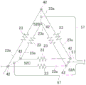
Fig. 12 is a diagram showing a wiring state of the coil.
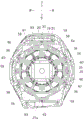
Fig. 13 is a sectional view taken along line a-a in fig. 2.
Fig. 14 (a) is a perspective view of the cylindrical case as viewed from the front, and fig. 14 (B) is a perspective view of the cylindrical case as viewed from the rear.
Fig. 15 (a) is a front view of the cylindrical case, and fig. 15 (B) is a cross-sectional view taken along line C-C.
Fig. 16 (a) is a sectional view taken along the line D-D, and fig. 16 (B) is a sectional view taken along the line C-C.
Fig. 17 is a perspective view of the brushless motor with the sensor circuit board facing backward.
Fig. 18 is a longitudinal sectional view of the sander.
Fig. 19 is a perspective view of the stator after changing the mounting position of the sensor circuit board.
Fig. 20 is an explanatory view of the stator after changing the mounting position of the sensor circuit board, where fig. 20 (a) shows the back surface of the stator, fig. 20 (B) shows the side surface of the stator, and fig. 20 (C) shows the front surface of the stator.
Fig. 21 is a sectional view taken along line F-F.
Fig. 22 is an explanatory view of a modification of the front insulator, in which fig. 22 (a) is a front view of the front insulator and fig. 22 (B) is a cross-sectional view taken along line G-G.
Fig. 23 is an explanatory view of a modification of the rear insulator, in which fig. 23 (a) is a front view of the rear insulator and fig. 23 (B) is a cross-sectional view taken along the line H-H.
[ description of reference ]
1: electric drill/screwdriver; 2: a main body; 6: a main body case; 17: a brushless motor; 18: a stator; 19: a rotor; 20: a stator core; 21: a front insulator; 22: a rear insulator; 23: a coil; 23 a: coiling; 24: a sensor circuit substrate; 25: a short-circuit member; 30: a holding section; 31: a protrusion; 35: a recess; 36: 1 st cut part; 37: a 2 nd cut portion; 40: a transverse cut portion; 42: a pressure welding terminal; 49: a signal line; 50: an insulating section; 52A: 1 st sheet metal part; 52B: a 2 nd sheet metal part; 52C: a 3 rd sheet metal part; 53: a shorting pad; 54: a connecting portion; 57: a power line; 61: a rotating shaft; 81: a cylindrical housing; 82: a receiving rib; 83: a stopper rib; 84: longitudinal ribs; 90: and (5) grinding machine.
Detailed Description
Hereinafter, embodiments of the present invention will be described with reference to the drawings.
Fig. 1 is an overall view of an electric drill/electric screwdriver as an example of an electric power tool, and fig. 2 is a longitudinal sectional view of a rear portion of a main body, in which the electric drill/electric screwdriver 1 has a T-shape, a handle 3 is formed downward on the main body 2 extending in a front-rear direction, and a battery pack 5 as a power source is attached to an attachment portion 4 formed at a lower end of the handle 3.
The housing portion of the main body 2 is formed as follows: a front housing 7 accommodating the clutch mechanism and the spindle is attached to the front (right side of the paper in fig. 1) of a cylindrical main body housing 6 accommodating a brushless motor 17 and a planetary gear reduction mechanism 72, which will be described later, from the front by a plurality of screws 8, and end cap housings 9 are attached to two upper and lower positions at the rear of the main body housing 6 from the rear by two screws 10. The connection surface between the body case 6 and the cap case 9 is formed in a female connection manner in which an annular projection 6c formed on the rear surface of the body case 6 and a recess 9a formed on the front surface of the cap case 9 are engaged with each other, wherein the projection 6c includes a projection with a screw hole and the recess 9a is screwed into the screw 10. A mode switching ring 11 and a clutch adjustment ring 12 are provided in front of the front housing 7, and a chuck 13 attached to the spindle is provided in front of the clutch adjustment ring 12. The handle 3 is connected to the main body case 6, and these members are formed by attaching the left and right half cases 6a and 6b together with a plurality of screws 14. 15 denotes a trigger provided on a switch housed in the handle 3, 16 denotes a forward/reverse switching button of a motor, and an unillustrated illumination lamp for illuminating the front of the chuck 13 is provided above the trigger 15.
The brushless motor 17 housed in the rear portion of the main body case 6 is an inner rotor motor including a stator 18 and a rotor 19, and as shown in fig. 3 to 5, the stator 18 includes a cylindrical stator core 20 formed of a plurality of laminated steel plates, a front insulator 21, a rear insulator 22, and 6 coils 23, the front insulator 21 and the rear insulator 22 are respectively provided on the front and rear end surfaces in the axial direction of the stator core 20, the 6 coils 23 are wound around the stator core 20 via the front and rear insulators 21 and 22, and a sensor circuit board 24 and a short-circuit member 25 are mounted on the front insulator 21.
First, the stator core 20 has 6 teeth 26 protruding toward the axial center side, and 6 slots 27 are formed between the teeth 26.
The front insulator 21 is an annular integrally molded member having the same diameter as the stator core 20, and 6 protruding portions 28 are formed on the inner peripheral side of the front insulator 21, and the protruding portions 28 protrude toward the axial center side and are continuous with the front sides of the teeth 26 of the stator core 20. Further, 6 fitting portions 29 to be fitted into the slots 27 of the stator core 20 are provided on the back surface side of the front insulator 21 in a protruding manner, and 6 sets of holding portions 30 of the pressure welding terminals 42 described later are provided on the front surface of the front insulator 21 in a protruding manner at positions corresponding to the fitting portions 29. The holding portion 30 is composed of a plurality of pairs of projections 31, grooves 32 of the projections 31 face each other between the projections 31 of each pair, the projections 31 are spaced apart by a predetermined interval, each holding portion 30 has a screw hole at the center, and a boss 33 with a screw hole formed by extending a flange portion 34 is provided at the root portion in a protruding manner.
As shown in fig. 7, a pair of recesses 35 serving as positioning portions are formed on the left and right side portions of the front insulator 21, and a pair of triangular 1 st notches 36 serving as positioning portions are formed on the upper and lower sides of the front insulator with the pair of recesses 35 interposed therebetween. A rectangular 2 nd notch 37 is formed at the center of the upper portion of the front insulator 21 as a positioning portion. The rear surfaces of the recess 35, the 1 st notch 36, and the 2 nd notch 37 are blocked by the stator core 20 (see fig. 7B).
Next, the rear insulator 22 is formed in a ring shape having the same diameter as that of the stator core 20, and 6 protruding portions 38 are formed on the inner peripheral side of the rear insulator 22, and the 6 protruding portions 38 protrude toward the axial center side and are continuous with the rear side of the tooth portions 26 of the stator core 20. Further, 6 fitting portions 39 to be fitted into the slots 27 of the stator core 20 are provided on the front surface side of the rear insulator 22. Two curved lateral notches 40 are formed in the left and right side portions of the rear insulator 22, and two chamfered portions 41 are formed at the center of the rear insulator 22 in the vertical direction by linear cutting.
The pressure welding terminal 42 is held by each holding portion 30 of the front insulator 21. The pressure welding terminal 42 is formed by folding a strip-shaped metal component in two, and has one end 43 bent in a convex shape at its middle portion and the other end 44 bent at its both side edges to form two blades 45 having L-shaped cross sections. Therefore, when the bent side of each pressure-welding terminal 42 is inserted into the holding portion 30 and the respective blades 45 are fitted into the groove portions 32 of the protrusions 31, the pressure-welding terminals 42 are arranged concentrically, and the end portion 43 is oriented outward, so that the entire pressure-welding terminal 42 and the front insulator 21 are oriented in parallel in the axial direction.
The plurality of coils 23 are wound around the teeth 26 of the stator core 20 via the protruding portions 28 and 38 of the front and rear insulators 21 and 22, and the coils 23 are wound around the circumferentially adjacent teeth 26 in sequence by one winding wire. The respective coils 23a connected to the respective coils 23 are connected to the pressure welding terminals 42 in a state of being sandwiched by the pressure welding terminals 42 through the outside of the holding portion 30, and are thereby electrically connected to the respective pressure welding terminals 42.
The sensor circuit board 24 is mounted with 3 rotation detecting elements (not shown) for detecting the position of the permanent magnet 63 provided on the rotor 19 and outputting a rotation detection signal, the sensor circuit board 24 has an outer diameter capable of being housed inside the holding portion 30 and has an outer shape in a donut shape, as shown in fig. 6, 4 projections 46 are provided extending on the outer periphery of the sensor circuit board 24, the 4 projections 46 have through holes 47 corresponding to the projections 33 with screw holes of the front insulator 21, and the projections 46 can be brought into contact with the flange portion 34 by passing the projections 33 with screw holes through the through holes 47, thereby positioning the sensor circuit board 24 on the front surface of the front insulator 21. A lead portion 48 of a plurality of signal lines 49 of the rotation detecting element is provided at the center of the lower portion of the sensor circuit board 24, and a heat shrinkable tube 48a with an adhesive is wrapped between the lead portion 48 and the signal lines 49. The heat shrinkable tube 48a can prevent disconnection of the signal line 49 and prevent water.
As shown in fig. 8 and 9, the short-circuit member 25 is annular and has a diameter substantially the same as that of the sensor circuit board 24, 4 tubular projections 51 integrally formed with the short-circuit member 25 are provided on the outer periphery of the resin insulating portion 50 in a protruding manner, and the projections of the screw holes of the front insulator 21 are fitted to the 4 projections from the rear. In addition, as shown in fig. 10, the insulating portion 50 is formed by insert molding three sheet metal members, i.e., a 1 st sheet metal member 52A, a 2 nd sheet metal member 52B, and a 3 rd sheet metal member 52C, made of sheet metal. The 1 st sheet metal part 52A is formed as follows: the lower connecting portion 54A is bent in a U-shape in the longitudinal direction (front-rear direction) while maintaining the thickness direction of the material in the radial direction, and a pair of short-circuit pieces 53 are formed by bending the both ends of the lower connecting portion 54A to the left and right outside. The 2 nd sheet metal part 52B is formed as follows: the thickness direction of the material is kept in the front-rear direction, a curved arc-shaped left connecting portion 54B is formed in the lateral direction, a pair of short-circuiting pieces 53 are provided on the lower right side and the upper left side of the left connecting portion 54B, and the central portion of the connecting portion 54B is bent rearward by two bent portions 54 d. The 3 rd sheet metal member 52C is formed as follows: a pair of shorting tabs 53 are provided on the lower left and upper right sides of the curved arc-shaped right connecting portion 54C, a lateral half portion of the connecting portion 54C is bent backward from the shorting tab 53 on the lower left side of the connecting portion 54C by the bent portion 54d, the remaining half portion is bent inward by the folded portion 54e so as to be oriented in the longitudinal direction, and the shorting tab 53 on the upper right side is bent outward. As shown in fig. 11, the 2 nd sheet metal part 52B is disposed behind the 1 st sheet metal part 52A on the left side, and the 3 rd sheet metal part 52C is disposed behind the 1 st sheet metal part 52A on the right side, and these three sheet metal parts 52A to 52C are formed in the insulating portion 50 by insert molding in a state of not contacting each other and overlapping on a concentric circle.
Accordingly, 6 short-circuit pieces 53 are formed to protrude from the outer periphery of the insulating portion 50, and the 6 short-circuit pieces 53 are arranged in a radial shape so as to correspond to the respective pressure-welding terminals 42 held on the front insulator 21, and the short-circuit pieces 53 at the opposite positions are electrically connected to each other. A notch 55 into which the other end 44 of the pressure welding terminal 42 can be inserted is formed at the tip of each short-circuit piece 53.
Further, a connection piece 56 is formed downward at the center of the lower end of the connection portion 54 of the 1 st sheet metal member 52A, the connection piece 56 is positioned between the short-circuit piece 53 on the lower side of the 2 nd sheet metal member 52B and the short-circuit piece 53 on the lower side of the 3 rd sheet metal member 52C, and the power supply lines 57 of the U-phase, the V-phase, and the W-phase are spot-welded to the rear surfaces of the short-circuit piece 53 on the lower sides of the 2 nd sheet metal member 52B and the 3 rd sheet metal member 52C and the connection piece 56. Two protrusions 56a for improving the coupling force with the insulating portion 50 are formed on the right and left sides of the coupling piece 56. A plurality of vertically parallel guide ribs 58 are provided upright on the lower end back surface of the insulating portion 50, and the plurality of guide ribs 58 guide the power supply line 57 downward from the sheet metal members 52A to 52C while spacing the power supply line 57 from each other, and hold the power supply line 57. Further, two guide projections 50a for guiding the left and right power supply lines 57 to the short-circuit piece 53 side are formed on the upper side of the guide rib 58 on the rear surface of the insulating portion 50, and two recesses 50b for positioning are formed on the inner peripheral side of the insulating portion 50. A through hole 50c for exposing the connection piece 56 and improving heat dissipation is formed in the lower portion of the insulating portion 50. The position P shown in fig. 8 and 10 indicates the bonding position of the power supply line 57.
When the projection 33 with the screw hole of the front insulator 21 is inserted into the projection 51, the short-circuit member 25 is overlapped with the sensor circuit board 24 from the front, and the short-circuit member 25 is fixed to the sensor circuit board 24 by a plurality of screws 88, the other end portion 44 of each pressure welding terminal 42 is inserted into the notch 55 of the corresponding short-circuit piece 53. Here, since the sheet metal member is not exposed from the rear surface of the insulating portion 50, it is in contact with the sensor circuit board 24 by the resin. Here, the center hole of the sensor circuit board 24 is smaller than the center hole of the short-circuit member 25.
When the pressure welding terminal 42 and the short-circuit piece 53 are welded in this state, the two pressure welding terminals 42 that are centrosymmetric are short-circuited by the 1 st to 3 rd sheet metal members 52A to 52C, respectively. As shown in fig. 12, the pressure welding terminals 42 are electrically connected to the respective coils 23a sequentially wound around the stator core 20, and the pressure welding terminals 42 at the respective opposing positions are electrically connected to each other by the 1 st to 3 rd sheet metal members 52A to 52C, thereby forming a so-called delta connection in which a plurality of wires are wound in parallel. S denotes the start of winding, and E denotes the end of winding.
Here, since the pressure welding terminal 42 and the short-circuit member 25 are separate components, and the short-circuit piece 53 of the short-circuit member 25 is welded after the coil 23 is wound, the short-circuit member 25 does not become an obstacle.
Although the pressure welding terminal 42 is formed to have a constant height to reliably perform welding, here, as shown in fig. 2 and 7(B), since the sensor circuit board 24 and the short-circuiting member 25 are arranged within the height dimension range of the pressure welding terminal 42, the entire length of the brushless motor 17 can be suppressed to the maximum extent even if the short-circuiting member 25 is used. Further, since all components except the signal lines and the power lines are concentrated within a range within the outer diameter of the stator core 20, the structure can be made compact without increasing the outer diameter of the product.
As shown in fig. 13, the outer periphery of the stator core 20 is held by a plurality of support ribs 59, and the stator 18 thus mounted is housed in a state of being positioned in the axial direction and the circumferential direction by fitting two protrusions 60, which are protrudingly provided on the inner surface of the half shell 6a of the main body case 6, into two recesses 35 formed on the side surface of the front insulator 21, respectively, wherein the plurality of support ribs 59 are protrudingly provided on the inner surface of the half shells 6a, 6b of the main body case 6 in the circumferential direction, respectively. When the stator 18 is housed in the half shells 6a and 6b, the stator 18 is easily attached in a desired direction by attaching the flat surface of the chamfered portion 41 so as to contact the support rib 59. The central recess of each projection 60 is formed by reducing the thickness, and the projection 60 is also formed on the half shell 6b, so that the stator 18 can be held more favorably.
As shown in fig. 2, the rotor 19 includes: a rotating shaft 61 located at the axial center; a cylindrical rotor core 62 disposed around the rotating shaft 61; and permanent magnets 63 arranged outside the rotor core 62, having a cylindrical shape, and having polarities alternately changing in the circumferential direction.
The rear end of the rotating shaft 61 is supported by a bearing 64 held by the end cap housing 9, and a centrifugal fan 65 is attached to a front portion of the rotating shaft 61. Here, the center portion of the centrifugal fan 65 is projected forward in a mortar shape, and the bearing 64 is configured to project rearward of the centrifugal fan 65. This shortens the distance between the end cap housing 9 and the centrifugal fan 65, thereby shortening the overall length. Reference numeral 66 denotes an intake port formed in the left and right side surfaces of the main body case 6 (see fig. 1), and 67 denotes a discharge port formed in the left and right side surfaces of the cap case 9 (see fig. 1 and 2).
In fig. 2, a gear case 68 housing a planetary gear reduction mechanism 72 is provided in front of the brushless motor 17, the front end of the rotating shaft 61 is inserted through an end cap 69 closing the rear end of the gear case 68, and is supported by a bearing 70 held by the end cap 69, and a pinion 71 is fixed to the rear end of the rotating shaft 61.
The planetary gear reduction mechanism 72 has a known structure in which a plurality of carriers 75 supporting a plurality of planetary gears 74 revolving in the ring gear 73 are arranged in parallel in the axial direction, and a second-stage ring gear 73A (denoted by 73A for convenience of distinction) is movable back and forth in the axial direction between a forward position and a backward position, wherein the second-stage ring gear 73A is fixed in the gear case 68 at a position where the second-stage planetary gears 74 revolve in the gear case 68 and is the forward position, and the second-stage ring gear 73A meshes with both the second-stage planetary gears 74 and the first-stage carrier 75, rotates the carriers 75 and the planetary gears 74 together, invalidates the reduction of the second stage, and at this time, the position where the second-stage ring gear 73A is located is the backward position. A speed switching ring 77 is connected to the internal gear 73A via a pin 76, and a protrusion 78 at the upper end of the speed switching ring 77 is connected to a speed switching button 80 via front and rear coil springs 79. Therefore, the inner gear 73A is moved forward and backward by the speed switching ring 77 by the operation of sliding the speed switching ring 80 forward and backward, and the low speed mode at the forward position and the high speed mode at the backward position can be selected.
In the electric drill/electric screwdriver 1 configured as described above, the trigger 15 is pressed to turn on the switch, and the brushless motor 17 is driven by the power supplied from the battery pack 5. That is, a microcomputer, not shown, housed in the lower portion of the handle 3 as a controller receives a rotation detection signal indicating the position of the permanent magnet 63 of the rotor 19 output from the rotation detection element of the sensor circuit board 24, obtains the rotation state of the rotor 19, and controls the on/off of each switching element based on the obtained rotation state to cause current to flow in sequence to each coil 23 of the stator 18, thereby rotating the rotor 19. Therefore, the rotation of the rotating shaft 61 is reduced by the planetary gear reduction mechanism 72 and transmitted to the spindle, thereby rotating the chuck 13. The mode switching ring 11 is operated to select an electric screwdriver mode and a power drill mode, and when the electric screwdriver mode is selected, a clutch mechanism for blocking rotation transmission by a predetermined torque is activated, whereas when the power drill mode is selected, the clutch mechanism is deactivated, and when the clutch adjusting ring 12 is operated, a torque generated when the clutch mechanism is activated can be adjusted in the electric screwdriver mode.
In addition, since the coils 23 of the brushless motor 17 are wound in parallel with a plurality of wires, the resistance of the coils can be reduced, and a large current can be allowed to flow. Since the coils 23 can be wound in parallel with a plurality of wires by using the short-circuiting member 25, space can be saved. That is, as shown in fig. 2, since the short-circuiting member 25 having a small thickness is positioned inside the holding portion 30 and is mounted so as not to protrude forward of the tip of the protrusion 31 of the holding portion 30, the short-circuiting member can be disposed by effectively utilizing the space in front of the sensor circuit board 24, and the compact configuration can be maintained.
Further, since 6 coils 23 are wound from one winding (so-called one-stroke molding), all the coils 23 can be wound in one process, and a crossover wire for connecting the coils at opposite positions is not required. Since no crossover is required, the structure can be made compact.
Further, since the sensor circuit board 24 is provided on one end side of the brushless motor 17 and the coil 23 can be supplied with power from the same side, a large current can be supplied while maintaining a compact configuration. In particular, by arranging the sensor circuit board 24 and the short-circuiting member 25 in this order on one end side of the stator 18, good sensor sensitivity can be obtained.
In the above-described embodiment, the brushless motor 17 is housed in the main body case 6 formed by the half- cases 6a and 6b, however, when the brushless motor 17 is housed in a cylindrical case for a circular saw or the like, for example, as shown in fig. 14 to 16, when the stator 18 of the brushless motor 17 is in a backward facing state with the short-circuit member 25 side facing backward, 4L-shaped receiving ribs 82 and plate-shaped stopper ribs 83 are provided at the bottom of the cylindrical case 81, wherein the top ends of the 4 receiving ribs 82 are respectively fitted with the 41 st notch parts 36 of the front insulator 21 of the stator 18, the top ends of the stopper ribs 83 are fitted with the 2 nd notch parts 37 of the front insulator 21 and are abutted with the end face of the stator core 20, a pair of vertical ribs 84 that contact the circumferential surface of the stator 18 are provided in front of the cylindrical tube 81, and the pair of vertical ribs 84 are symmetrical in the vertical direction and the lateral direction. And 81a represents a housing recess of the bearing. In this way, the cylindrical housing 81 is provided with an engagement portion that engages with the insulator or the stator, whereby the stator 18 can be mounted well.
Further, two bosses 85 with screw holes are provided between the two right and left vertical ribs 84, the height of the two bosses 85 with screw holes is set to be flush with the end face of the stator core 20 in the housed state, and by inserting screws 86 into the bosses 85 with screw holes from the front through washers 87, the washers 87 can be fitted into the lateral cutout portions 40 of the rear insulators 22, thereby pressing the end face of the stator core 20 from the front.
Therefore, the stator 18 is restricted from moving backward by the receiving rib 82 and restricted from moving in the circumferential direction by the stopper rib 83, and the stator 18 is centered in the cylindrical case 81 by the vertical rib 84 so that the center thereof coincides with the center of the cylindrical case 81. The forward movement of the stator 18 is restricted by a screw 86 and a washer 87. Further, since the guide portion 21a is provided so as to protrude from the front insulator 21, when the stator 18 is pressed in, the stator 18 can be smoothly arranged at a desired position by merely press-fitting the guide portion 21a between the two vertical ribs 84 as shown in fig. 15 (a). After the pressing operation is completed, the position of the stator 18 in the circumferential direction is also determined.
In this way, even in the case of the cylindrical case 81, the stator 18 can be easily positioned by the notch portions 36, 37, and 40 provided in the front and rear insulators 21 and 22, and the front and rear insulators 21 and 22 can be made common.
In the above embodiment, the signal line 49 of the sensor circuit board 24 and the power line 57 of the short-circuiting member 25 are drawn from the same side (lower side), but the signal line 49 may be drawn from the upper side by changing the mounting angle of the sensor circuit board 24 by 180 ° as in the stator 18 shown in fig. 17. Thus, even when the motor case 19 housing the brushless motor 17 also serves as a grip portion as in the sander 90 shown in fig. 18, for example, the protrusion of the motor case 91 on the side of the power supply line 57 is suppressed, and the motor case 91 can be made more slender in this portion. In addition, even in the case of another configuration, wiring can be easily performed, and the insulator can be made common. In fig. 18, 92 denotes a controller, 93 denotes a switch connected between the controller 92 and a lead 94, 95 denotes a slide button for opening or closing the switch 93 via a connecting rod 96, and 97 denotes a front case for projecting a main shaft 98 downward.
The sensor circuit board 24 may be provided on the opposite side of the short-circuiting member 25. That is, as shown in the stator 18A shown in fig. 19 to 21, the sensor circuit board 24 is provided on the rear surface of the rear insulator 22, and here, the sensor circuit board 24 is attached to the cylindrical case by forming the lateral cut portion 22a and the chamfered portion 22b on the outer periphery thereof so as to be aligned with the lateral cut portion 40 and the chamfered portion 41 provided on the rear insulator 22. Reference numeral 99 denotes a screw, and 100 denotes a rotation detecting element (hall IC), and in this case, the position of the permanent magnet provided on the centrifugal fan 65 is detected by the rotation detecting element 100. Therefore, although the short-circuiting member 25 can be mounted on the front insulator 21 without passing through the sensor circuit board 24, the short-circuiting member 25 is disposed by fitting the concave portion on the back side of the boss 51 to the upper surface of the threaded boss 33 of the front insulator 21, and therefore the position of the short-circuiting member 25 does not change even if the sensor circuit board 24 is not disposed. The short-circuit member 25 is positioned by the concave-convex fitting of the threaded projection 33 and the projection 55. In fig. 19, 22c denotes a plurality of projections projecting from the rear surface of the rear insulator 22, and the plurality of projections 22c are inserted into through holes provided in the sensor circuit board 24 to cause thermal deformation, thereby preventing the sensor circuit board 24 from coming off.
The structure of the insulator may be appropriately changed. Fig. 22 shows a modification of the front insulator, and fig. 23 shows a modification of the rear insulator, in which first, in the front insulator 21, a groove 28a is formed in a direction perpendicular to the protruding portion 28 on the front surface side of the root portion of each protruding portion 28, and two relief portions 28b formed in a concave shape in the radial direction are formed on both sides in the circumferential direction of the root portion of each protruding portion 28. Similarly, in the rear insulator 22, a groove 38a is formed in a direction perpendicular to the protruding portion 38 on the rear surface side of the root portion of each protruding portion 38, and two relief portions 38b formed in a concave shape in the radial direction are formed on both sides in the circumferential direction of the root portion of each protruding portion 38.
The notches 28a and 38a are used for fitting one winding of the coil 23 at the start of winding each tooth 26, and the one winding is just fitted into the recesses 28a and 38a for winding, whereby the second and subsequent windings are also wound in line. Further, the lead tap for winding the coil 23 is easily inserted through the relief portions 28b and 38b, and a plurality of recesses 38c for smoothly winding the coil 23 are formed on both sides of the root portion of the protruding portion 38 on the inner peripheral surface of the rear insulator 22.
Here, the two lateral notches 40 are located between the two protruding portions 38, and the protruding portions 38 are located between the surfaces of the two chamfered portions 41, so that the outer periphery of the rear insulator 22 is not easily enlarged.
In the above embodiment, the short-circuiting means is constituted by the short-circuiting member and the pressure-welding terminals, but the pressure-welding terminals may be omitted and the short-circuiting between the winding wires may be caused only by the short-circuiting member, or conversely, the short-circuiting member may be omitted and the pressure-welding terminals may be connected by the lead wires.
The present invention is applicable to a cleaner, a garden tool such as a blower, and the like as well as a power tool, not limited to a type that performs a machining operation by driving a tool bit such as an electric drill, an electric screwdriver, a circular saw, and a sander. The present invention can also be applied to an electric power tool using a sensorless brushless motor that is not equipped with a sensor circuit board.
Claims (6)
1. An electric power tool having a motor including a stator and a rotor, insulators provided on both front and rear sides of the stator in an axial direction, and a plurality of coils wound around the stator via the insulators,
at least 6 of the coils are arranged in the coil,
a short-circuit mechanism for generating short-circuit between the coils at the opposite positions is arranged,
the short-circuiting mechanism has a plurality of short-circuiting pieces (53) for short-circuiting the coils at the opposite positions, and an insulating part (50) for holding the short-circuiting pieces (53),
a terminal (42) connected to the coil is held on the insulator,
the short-circuiting mechanism has:
a plurality of sheet metal members (52A, 52B, 52C) electrically connecting the coils disposed to face each other;
the insulating part made of resin for holding the sheet metal member,
the short-circuiting piece (53) is formed at an end portion of the sheet metal member,
the sheet metal member has a bent connection portion and the short-circuit pieces formed at both ends of the connection portion,
the plurality of sheet metal parts includes:
a 1 st sheet metal member (52A) having a connecting portion with a thickness direction directed in a radial direction;
a 2 nd sheet metal member (52B) having a connecting portion with a thickness direction oriented in an axial direction;
a 3 rd sheet metal member (52C) having a connecting portion in which a thickness direction of a part thereof is oriented in an axial direction and a thickness direction of another part thereof is oriented in a radial direction, the connecting portion and the part being connected by a folded portion (54e),
the 1 st to 3 rd sheet metal members (52A to 52C) are arranged so as not to contact each other and so as to overlap each other concentrically.
2. The power tool of claim 1,
the stator (18) is provided with a sensor circuit board (24) and the short-circuit means arranged in parallel on one end side in the axial direction in this order,
disposing the sensor circuit substrate between the insulator and the short-circuiting mechanism, the sensor circuit substrate having a rotation detecting element for detecting a position of a permanent magnet disposed on the rotor,
the coil is formed by winding one winding wire.
3. The power tool of claim 1,
the short-circuiting pieces (53) are provided so that the thickness direction thereof faces the axial direction of the stator, and each short-circuiting piece (53) is provided with a notch (55) into which the terminal (42) is inserted in the axial direction.
4. The power tool of claim 1,
the plurality of sheet metal members include a 1 st sheet metal member (52A) having a bent connection portion (54A) and the shorting tab formed at both ends of the connection portion (54A),
a connecting piece (56) extending in a radial outer direction of the stator is formed on a connecting portion (54A) of the 1 st sheet metal member (52A), the connecting piece (56) is connected to a power supply line (57),
protrusions (56a) for increasing the coupling force with the insulating portion (50) are formed on both sides of the connection piece (56).
5. The power tool of claim 2,
the sensor circuit board can change the installation angle when being installed.
6. An electric power tool having a motor including a stator and a rotor, insulators provided on both front and rear sides of the stator in an axial direction, and a plurality of coils wound around the stator via the insulators,
a housing for housing the motor is formed by combining a pair of half shells, a positioning part engaged with the inner surfaces of the half shells is arranged on the stator,
6 terminals are held on the insulator, 6 coils are connected to the 6 terminals,
the electric tool has a short-circuit member fixed to the insulator by a screw and connected to the terminal to short-circuit the coils at opposite positions,
the short-circuit part has 3 sheet metal parts connected to the terminals,
the sheet metal member has a bent connection portion and the short-circuit pieces formed at both ends of the connection portion,
the 3 sheet metal parts comprise:
a 1 st sheet metal member (52A) having a connecting portion with a thickness direction directed in a radial direction;
a 2 nd sheet metal member (52B) having a connecting portion with a thickness direction oriented in an axial direction;
a 3 rd sheet metal member (52C) having a connecting portion in which a thickness direction of a part thereof is oriented in an axial direction and a thickness direction of another part thereof is oriented in a radial direction, the connecting portion and the part being connected by a folded portion (54e),
the 1 st to 3 rd sheet metal members (52A to 52C) are arranged so as not to contact each other and so as to overlap each other concentrically.
Applications Claiming Priority (2)
| Application Number | Priority Date | Filing Date | Title |
|---|---|---|---|
| JP2013-188528 | 2013-09-11 | ||
| JP2013188528A JP6234128B2 (en) | 2013-09-11 | 2013-09-11 | Electric tool |
Publications (2)
| Publication Number | Publication Date |
|---|---|
| CN104426274A CN104426274A (en) | 2015-03-18 |
| CN104426274B true CN104426274B (en) | 2020-06-19 |
Family
ID=51609897
Family Applications (1)
| Application Number | Title | Priority Date | Filing Date |
|---|---|---|---|
| CN201410312524.4A Active CN104426274B (en) | 2013-09-11 | 2014-07-02 | Electric tool |
Country Status (4)
| Country | Link |
|---|---|
| US (4) | US9948162B2 (en) |
| EP (1) | EP2849316B1 (en) |
| JP (1) | JP6234128B2 (en) |
| CN (1) | CN104426274B (en) |
Families Citing this family (53)
| Publication number | Priority date | Publication date | Assignee | Title |
|---|---|---|---|---|
| US9450471B2 (en) | 2012-05-24 | 2016-09-20 | Milwaukee Electric Tool Corporation | Brushless DC motor power tool with combined PCB design |
| US9787159B2 (en) | 2013-06-06 | 2017-10-10 | Milwaukee Electric Tool Corporation | Brushless DC motor configuration for a power tool |
| JP6234128B2 (en) | 2013-09-11 | 2017-11-22 | 株式会社マキタ | Electric tool |
| JP6389362B2 (en) | 2013-12-25 | 2018-09-12 | 株式会社マキタ | Electric tool |
| JP6414224B2 (en) * | 2014-08-29 | 2018-10-31 | 工機ホールディングス株式会社 | Electric working machine |
| US10236742B2 (en) | 2014-11-25 | 2019-03-19 | Black & Decker Inc. | Brushless motor for a power tool |
| WO2016090306A1 (en) * | 2014-12-05 | 2016-06-09 | Nidec Motor Corporation | Electric motor |
| JP6626632B2 (en) * | 2015-05-13 | 2019-12-25 | 株式会社マキタ | Electric tool |
| JP6635676B2 (en) * | 2015-05-13 | 2020-01-29 | 株式会社マキタ | Electric tool |
| US10193422B2 (en) | 2015-05-13 | 2019-01-29 | Makita Corporation | Power tool |
| JP6514970B2 (en) * | 2015-06-25 | 2019-05-15 | 株式会社マキタ | Electric tool |
| US10328566B2 (en) | 2015-10-14 | 2019-06-25 | Black & Decker Inc. | Brushless motor system for power tools |
| JP6652811B2 (en) * | 2015-10-27 | 2020-02-26 | 株式会社ミツバ | motor |
| CN108430710A (en) * | 2015-11-20 | 2018-08-21 | 创科(澳门离岸商业服务)有限公司 | Electric tool with integrated circuit board |
| JP6596343B2 (en) * | 2016-01-26 | 2019-10-23 | 株式会社マキタ | Electric tool |
| CN110912341B (en) | 2016-03-30 | 2022-03-18 | 米沃奇电动工具公司 | Brushless motor for electric tool |
| JP6635338B2 (en) * | 2016-04-15 | 2020-01-22 | ミネベアミツミ株式会社 | Rotating device |
| JP2018019564A (en) * | 2016-07-29 | 2018-02-01 | 株式会社マキタ | Coil forming method for power tool motor, power tool |
| KR102215005B1 (en) * | 2016-08-11 | 2021-02-10 | 한온시스템 주식회사 | Brushless direct current motor |
| DE102016224425A1 (en) * | 2016-12-08 | 2018-06-14 | Robert Bosch Gmbh | Stator for a multi-phase electric motor, method for producing a coil winding, and electric motor for a hand-held tool |
| DE102016226200A1 (en) * | 2016-12-23 | 2018-06-28 | Bühler Motor GmbH | Brushless motor |
| JP6819286B2 (en) * | 2016-12-29 | 2021-01-27 | 工機ホールディングス株式会社 | Electric tool |
| KR200493636Y1 (en) * | 2017-02-13 | 2021-05-06 | 밀워키 일렉트릭 툴 코포레이션 | Brushless DC motor for power tools |
| JP6968581B2 (en) | 2017-06-12 | 2021-11-17 | 株式会社マキタ | Electric tool |
| US20200119600A1 (en) | 2017-06-14 | 2020-04-16 | Makita Corporation | Electric tool |
| JP7282153B2 (en) * | 2017-06-14 | 2023-05-26 | 株式会社マキタ | Electric tool |
| JP6968600B2 (en) * | 2017-07-03 | 2021-11-17 | 株式会社マキタ | Electric tool |
| JP7025851B2 (en) | 2017-07-03 | 2022-02-25 | 株式会社マキタ | How to repair power tools and power tools |
| CN109787392A (en) * | 2017-11-14 | 2019-05-21 | 南京德朔实业有限公司 | A kind of electric tool and motor and stator apparatus |
| CN111479658B (en) * | 2017-12-19 | 2023-10-27 | 株式会社牧田 | Electric working machine and method for constructing electric system in electric working machine |
| US10987784B2 (en) | 2018-02-23 | 2021-04-27 | Ingersoll-Rand Industrial U.S., Inc. | Cordless impact tool with brushless, sensorless, motor and drive |
| DE102018105337A1 (en) * | 2018-03-08 | 2019-09-12 | Ebm-Papst St. Georgen Gmbh & Co. Kg | Stator arrangement with winding arrangement |
| JP7124400B2 (en) * | 2018-04-10 | 2022-08-24 | 株式会社デンソー | drive |
| JP7129820B2 (en) * | 2018-05-15 | 2022-09-02 | 株式会社マキタ | Electric tool |
| TWI668941B (en) * | 2018-05-30 | 2019-08-11 | 朝程工業股份有限公司 | Method for manufacturing stator of brushless motor and stator of brushless motor |
| CN108631480B (en) * | 2018-07-03 | 2020-05-01 | 宁波领越智能设备有限公司 | Gardening electric mowing tool |
| CN108808931B (en) * | 2018-07-03 | 2020-04-28 | 宁波领越智能设备有限公司 | Motor of gardening mowing electric tool and assembling method thereof |
| JP7179569B2 (en) | 2018-10-05 | 2022-11-29 | 株式会社マキタ | electric garden tools |
| JP7170518B2 (en) * | 2018-11-29 | 2022-11-14 | 株式会社マキタ | Electric tool |
| CN113348606B (en) | 2018-11-29 | 2023-12-01 | 米沃奇电动工具公司 | Motor winding design for an electric motor |
| JP7210261B2 (en) | 2018-12-14 | 2023-01-23 | 株式会社マキタ | ELECTRIC WORKING MACHINE AND METHOD FOR MANUFACTURING STATOR IN MOTOR FOR ELECTRIC WORKING MACHINE |
| JP7190511B2 (en) * | 2018-12-26 | 2022-12-15 | 株式会社マキタ | electric work machine |
| DE102019111335A1 (en) * | 2019-05-02 | 2020-11-05 | Festool Gmbh | Drive motor with a connection device |
| US11621613B2 (en) * | 2019-07-22 | 2023-04-04 | Techway Industrial Co., Ltd. | Electric motor and electric tool |
| JP2021044940A (en) * | 2019-09-11 | 2021-03-18 | 株式会社マキタ | Electric work machine |
| EP3829039A1 (en) * | 2019-11-29 | 2021-06-02 | Hilti Aktiengesellschaft | Hall pcb with bearing passage opening |
| US11509193B2 (en) | 2019-12-19 | 2022-11-22 | Black & Decker Inc. | Power tool with compact motor assembly |
| US11705778B2 (en) | 2019-12-19 | 2023-07-18 | Black & Decker Inc. | Power tool with compact motor assembly |
| US11949295B2 (en) | 2020-04-21 | 2024-04-02 | Milwaukee Electric Tool Corporation | Power tool printed circuit board including embedded busbars |
| JP2022012823A (en) | 2020-07-02 | 2022-01-17 | 株式会社マキタ | Electric work machine |
| US11685036B2 (en) | 2020-07-27 | 2023-06-27 | Techtronic Cordless Gp | Motor mounting assembly for a power tool |
| US11876424B2 (en) | 2021-02-02 | 2024-01-16 | Black & Decker Inc. | Compact brushless motor including in-line terminals |
| US20230182270A1 (en) | 2021-12-13 | 2023-06-15 | Makita Corporation | Impact tool |
Citations (3)
| Publication number | Priority date | Publication date | Assignee | Title |
|---|---|---|---|---|
| WO2009145205A1 (en) * | 2008-05-29 | 2009-12-03 | Hitachi Koki Co., Ltd. | Electric power tool |
| JP2010273525A (en) * | 2009-05-25 | 2010-12-02 | Mitsubishi Electric Corp | Stator of motor, motor, air conditioner, and method of manufacturing motor |
| WO2011155327A1 (en) * | 2010-06-10 | 2011-12-15 | 本田技研工業株式会社 | Salient pole concentrated winding stator for electric motor and manufacturing method for same |
Family Cites Families (54)
| Publication number | Priority date | Publication date | Assignee | Title |
|---|---|---|---|---|
| US1372250A (en) * | 1920-01-12 | 1921-03-22 | Harold M Sanford | Internal-combustion motor |
| US3135881A (en) * | 1960-12-02 | 1964-06-02 | Aesup Ets | Electrically-operated hand appliances |
| CA1071680A (en) * | 1976-06-16 | 1980-02-12 | Itw Fastex Italia S.P.A. | Insulating assembly for stator slots of electrical motors |
| US4132460A (en) * | 1977-11-07 | 1979-01-02 | Amp Incorporated | Electrical connections to coil windings |
| DE59008112D1 (en) * | 1989-07-15 | 1995-02-09 | Kress Elektrik Gmbh & Co | Power tool. |
| US5103127A (en) * | 1991-02-25 | 1992-04-07 | General Motors Corporation | Torque converter mounted starter/generator for a motor vehicle |
| JPH06233483A (en) * | 1993-01-29 | 1994-08-19 | Honda Motor Co Ltd | Connection structure of coil winding in stator |
| WO2000033442A1 (en) * | 1998-12-02 | 2000-06-08 | Siemens Aktiengesellschaft | Conductor arrangement with a plurality of electrical conductors for conveying power to and from a winding arrangement |
| JP2002281723A (en) * | 2001-03-19 | 2002-09-27 | Denso Corp | Dc motor and controlling method therefor |
| JP2003134753A (en) * | 2001-10-26 | 2003-05-09 | Sumitomo Wiring Syst Ltd | Method for manufacturing centralized distribution member of thin brushless motor for vehicle |
| GB0130602D0 (en) * | 2001-12-21 | 2002-02-06 | Johnson Electric Sa | Brushless D.C. motor |
| DE50204496D1 (en) * | 2002-01-22 | 2006-02-16 | Ebm Papst St Georgen Gmbh & Co | stator |
| CN1323787C (en) * | 2002-02-04 | 2007-07-04 | 密尔沃基电动工具公司 | Electrical devices including a switched reluctance motor |
| ITMI20020308U1 (en) * | 2002-06-11 | 2003-12-11 | Elco Spa | STRUCTURE OF AN ELECTRONICALLY COMMUTED ELECTRIC MOTOR |
| US6822364B2 (en) * | 2002-07-30 | 2004-11-23 | Asmo Co., Ltd. | Brushless motor |
| JP4320587B2 (en) * | 2003-11-28 | 2009-08-26 | 株式会社ジェイテクト | Electric power steering apparatus and manufacturing method thereof |
| JP2005341640A (en) * | 2004-05-24 | 2005-12-08 | Koyo Seiko Co Ltd | Stator of motor |
| JP2006027355A (en) * | 2004-07-13 | 2006-02-02 | Nsk Ltd | Electric power steering device |
| JP4781653B2 (en) * | 2004-10-21 | 2011-09-28 | 株式会社マキタ | Electric tool |
| WO2006050765A1 (en) * | 2004-11-10 | 2006-05-18 | Ebm-Papst St. Georgen Gmbh & Co. Kg | Electric motor |
| JP4783012B2 (en) * | 2004-12-28 | 2011-09-28 | 日立オートモティブシステムズ株式会社 | Electric power steering motor and manufacturing method thereof |
| JP5025999B2 (en) * | 2006-06-09 | 2012-09-12 | 株式会社マキタ | DC brushless motor for electric tools |
| JP2008067571A (en) * | 2006-09-11 | 2008-03-21 | Jtekt Corp | Motor and electric pump |
| DE202007014169U1 (en) | 2006-10-14 | 2008-02-28 | Ebm-Papst St. Georgen Gmbh & Co. Kg | electric motor |
| DE102008006399A1 (en) * | 2007-02-02 | 2008-08-07 | Groschopp Ag Drives & More | Three phase machine e.g. brushless direct current motor, for use in fan motor application, has stator including coil system provided as rotary field coil, where machine is designed as asynchronous machine with active squirrel-cage rotor |
| US8253285B2 (en) * | 2007-04-27 | 2012-08-28 | Hitachi Koki Co., Ltd. | Power tool |
| JP5013314B2 (en) * | 2007-06-18 | 2012-08-29 | 日立工機株式会社 | Electric tool |
| JP2009033786A (en) * | 2007-07-24 | 2009-02-12 | Mabuchi Motor Co Ltd | Inner rotor brushless motor incorporating bus bar |
| JP5256669B2 (en) | 2007-08-30 | 2013-08-07 | 株式会社ジェイテクト | Brushless motor and electric power steering device |
| JP2009118615A (en) * | 2007-11-05 | 2009-05-28 | Mitsuba Corp | Brushless motor |
| CN102046335B (en) * | 2008-05-29 | 2015-09-09 | 日立工机株式会社 | Electric tool |
| JP4913779B2 (en) | 2008-06-27 | 2012-04-11 | 株式会社杉山製作所 | Brushless motor terminal insert molding method and terminal |
| JP5512110B2 (en) * | 2008-09-26 | 2014-06-04 | 株式会社マキタ | Electric tool |
| CN102149515B (en) * | 2009-01-30 | 2014-08-06 | 日立工机株式会社 | Power tool |
| JP5478987B2 (en) | 2009-08-21 | 2014-04-23 | 株式会社マキタ | Electric tool |
| US20110094577A1 (en) * | 2009-10-28 | 2011-04-28 | Dilip Kumar Chatterjee | Conductive metal oxide films and photovoltaic devices |
| JP2011094577A (en) * | 2009-11-02 | 2011-05-12 | Panasonic Electric Works Co Ltd | Pump and pump drive equipment |
| US8786159B2 (en) * | 2009-12-28 | 2014-07-22 | Toyota Jidosha Kabushiki Kaisha | Fixing structure for stator core and rotating electric machine including the same |
| JP5740930B2 (en) * | 2010-03-03 | 2015-07-01 | 日本電産株式会社 | Stator and motor |
| WO2011159674A1 (en) * | 2010-06-14 | 2011-12-22 | Black & Decker Inc. | Stator assembly for a brushless motor in a power tool |
| JP5534562B2 (en) * | 2010-07-14 | 2014-07-02 | 日立工機株式会社 | Electric tool |
| JP2012090497A (en) * | 2010-10-22 | 2012-05-10 | Jtekt Corp | Brushless motor and electric power steering device |
| US8907810B2 (en) * | 2010-12-02 | 2014-12-09 | Masco Corporation | Water usage monitoring system |
| JP5679512B2 (en) | 2010-12-28 | 2015-03-04 | 日立工機株式会社 | Electric tool |
| US8916999B2 (en) * | 2011-01-01 | 2014-12-23 | Asmo Co., Ltd. | Motors containing segment conductor coils |
| JP2012228007A (en) * | 2011-04-15 | 2012-11-15 | Asmo Co Ltd | Bus bar device, stator, motor and manufacturing method of stator |
| JP5743085B2 (en) * | 2011-06-15 | 2015-07-01 | 日立工機株式会社 | Electric tool |
| JP5872807B2 (en) | 2011-07-12 | 2016-03-01 | ミネベア株式会社 | Connection structure of coil winding in motor and motor |
| JP5722156B2 (en) | 2011-08-02 | 2015-05-20 | 株式会社マキタ | Electric tool |
| CN102403815A (en) | 2011-11-17 | 2012-04-04 | 许晓华 | Connection structure of motor stator and stator circuit board |
| JP5459563B2 (en) * | 2011-12-21 | 2014-04-02 | 株式会社デンソー | Brushless motor |
| US9806566B2 (en) * | 2012-08-30 | 2017-10-31 | Asmo Co., Ltd. | Brushless motor, stator, stator manufacturing method and brushless motor manufacturing method |
| JP5554427B2 (en) | 2013-02-21 | 2014-07-23 | 株式会社マキタ | Electric tool with DC brushless motor |
| JP6234128B2 (en) | 2013-09-11 | 2017-11-22 | 株式会社マキタ | Electric tool |
-
2013
- 2013-09-11 JP JP2013188528A patent/JP6234128B2/en active Active
-
2014
- 2014-07-02 CN CN201410312524.4A patent/CN104426274B/en active Active
- 2014-09-09 US US14/481,237 patent/US9948162B2/en active Active
- 2014-09-11 EP EP14184351.6A patent/EP2849316B1/en active Active
-
2018
- 2018-03-13 US US15/919,615 patent/US10903718B2/en active Active
-
2020
- 2020-12-15 US US17/122,601 patent/US11715995B2/en active Active
-
2023
- 2023-12-27 US US18/397,480 patent/US20240128834A1/en active Pending
Patent Citations (3)
| Publication number | Priority date | Publication date | Assignee | Title |
|---|---|---|---|---|
| WO2009145205A1 (en) * | 2008-05-29 | 2009-12-03 | Hitachi Koki Co., Ltd. | Electric power tool |
| JP2010273525A (en) * | 2009-05-25 | 2010-12-02 | Mitsubishi Electric Corp | Stator of motor, motor, air conditioner, and method of manufacturing motor |
| WO2011155327A1 (en) * | 2010-06-10 | 2011-12-15 | 本田技研工業株式会社 | Salient pole concentrated winding stator for electric motor and manufacturing method for same |
Also Published As
| Publication number | Publication date |
|---|---|
| US20150069864A1 (en) | 2015-03-12 |
| JP6234128B2 (en) | 2017-11-22 |
| EP2849316B1 (en) | 2018-07-11 |
| CN104426274A (en) | 2015-03-18 |
| EP2849316A3 (en) | 2016-01-06 |
| US20180205288A1 (en) | 2018-07-19 |
| US10903718B2 (en) | 2021-01-26 |
| US20240128834A1 (en) | 2024-04-18 |
| US11715995B2 (en) | 2023-08-01 |
| US9948162B2 (en) | 2018-04-17 |
| EP2849316A2 (en) | 2015-03-18 |
| US20210099053A1 (en) | 2021-04-01 |
| JP2015056953A (en) | 2015-03-23 |
Similar Documents
| Publication | Publication Date | Title |
|---|---|---|
| CN104426274B (en) | Electric tool | |
| CN106160390B (en) | Electric tool | |
| EP2889107B1 (en) | Power tool | |
| US10608500B2 (en) | Electric power tool | |
| CN111869060A (en) | Electric tool | |
| JP6334914B2 (en) | Electric tool | |
| JP2016214042A (en) | Electric tool | |
| US10270321B2 (en) | Electric motor | |
| JP5955927B2 (en) | Electric tool | |
| JP2015126563A (en) | Electric tool | |
| JP2016097487A (en) | Impact tool and method of manufacturing spindle for impact tool | |
| JP7210261B2 (en) | ELECTRIC WORKING MACHINE AND METHOD FOR MANUFACTURING STATOR IN MOTOR FOR ELECTRIC WORKING MACHINE | |
| JP2016214041A (en) | Electric power tool | |
| JP2012191792A (en) | Electric power supply means and motor unit | |
| JP7129820B2 (en) | Electric tool | |
| US11628553B2 (en) | Power tool | |
| JP2014039378A (en) | Wiper motor | |
| JP2014023186A (en) | Brush holder device and motor | |
| CN114207991A (en) | Electric working machine |
Legal Events
| Date | Code | Title | Description |
|---|---|---|---|
| C06 | Publication | ||
| PB01 | Publication | ||
| C10 | Entry into substantive examination | ||
| SE01 | Entry into force of request for substantive examination | ||
| GR01 | Patent grant | ||
| GR01 | Patent grant |