EP2849205A1 - Mass spectrometer - Google Patents
Mass spectrometer Download PDFInfo
- Publication number
- EP2849205A1 EP2849205A1 EP12876541.9A EP12876541A EP2849205A1 EP 2849205 A1 EP2849205 A1 EP 2849205A1 EP 12876541 A EP12876541 A EP 12876541A EP 2849205 A1 EP2849205 A1 EP 2849205A1
- Authority
- EP
- European Patent Office
- Prior art keywords
- vacuum chamber
- detector
- ion
- vibration
- mass spectrometer
- Prior art date
- Legal status (The legal status is an assumption and is not a legal conclusion. Google has not performed a legal analysis and makes no representation as to the accuracy of the status listed.)
- Withdrawn
Links
Images
Classifications
-
- H—ELECTRICITY
- H01—ELECTRIC ELEMENTS
- H01J—ELECTRIC DISCHARGE TUBES OR DISCHARGE LAMPS
- H01J49/00—Particle spectrometers or separator tubes
- H01J49/02—Details
- H01J49/025—Detectors specially adapted to particle spectrometers
-
- H—ELECTRICITY
- H01—ELECTRIC ELEMENTS
- H01J—ELECTRIC DISCHARGE TUBES OR DISCHARGE LAMPS
- H01J49/00—Particle spectrometers or separator tubes
- H01J49/02—Details
- H01J49/06—Electron- or ion-optical arrangements
- H01J49/068—Mounting, supporting, spacing, or insulating electrodes
-
- G—PHYSICS
- G01—MEASURING; TESTING
- G01T—MEASUREMENT OF NUCLEAR OR X-RADIATION
- G01T1/00—Measuring X-radiation, gamma radiation, corpuscular radiation, or cosmic radiation
- G01T1/16—Measuring radiation intensity
- G01T1/28—Measuring radiation intensity with secondary-emission detectors
-
- H—ELECTRICITY
- H01—ELECTRIC ELEMENTS
- H01J—ELECTRIC DISCHARGE TUBES OR DISCHARGE LAMPS
- H01J49/00—Particle spectrometers or separator tubes
- H01J49/02—Details
- H01J49/24—Vacuum systems, e.g. maintaining desired pressures
Definitions
- the present invention relates to a mass spectrometer, and more specifically, to the structure of a mass spectrometer.
- mass spectrometers are configured so that ions generated from a sample component are separated according to their mass-to-charge ratios in a quadrupole mass filter or similar mass analyzer placed in a high-vacuum atmosphere and the separated ions are detected by an ion detector.
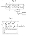
- Fig. 3 is a schematic configuration diagram of a common type of quadrupole mass spectrometer.
- An almost hermetically sealed vacuum chamber 1 contains an EI ion source 2, an ion lens 3, a quadrupole mass filter 4, an ion detector 5 and other elements arranged along an ion beam axis C.
- EI ion source 2 When a gas containing a sample component is introduced into the EI ion source 2, the sample component comes in contact with thermions and is ionized. The generated ions are extracted from the EI ion source 2 and focused by the ion lens 3, to be introduced into the quadrupole mass filter 4 consisting of four rod electrodes.
- a preset amount of voltage composed of a radio-frequency voltage superposed on a direct-current voltage is applied from a power source (not shown) to each of the rod electrodes of the quadrupole mass filter 4. Only an ion having a mass-to-charge ratio corresponding to the voltage passes through the quadrupole mass filter 4 and reaches the ion detector 5.
- a secondary electron multiplier (EPM) is commonly used (see Patent Literature 1).
- FIG. 4 is a schematic configuration diagram of an ion detector 5 using a secondary electron multiplier.
- Each of the dynodes 51-56 arranged in a cascade structure is supplied with a preset amount of voltage from a power source 58.
- a power source 58 When an ion which has come from the left side on the figure and passed through the ion entrance 50 collides with the first conversion dynode 51, secondary electrons are emitted, which are then accelerated by an electric field and made to collide with the second dynode 52, which in turn emits a larger amount of secondary electrons.
- Such a process is repeated at each of the diodes 53 ...
- the secondary electrons thus multiplied are made to enter a collector 57, and an electric current thereby generated in the collector 57 is extracted through a signal cable 59 as the detection signal.
- turbomolecular pumps perform evacuation in molecular units through interaction between moving blades (which are formed on a rotor rotated at high speeds) and stationary blades. Since the rotor is rotated at high speeds of up to several ten thousand rpm, turbomolecular pumps normally cause significant vibrations. In a system having a configuration as shown in Fig. 3 , this mechanical vibration of the turbomolecular pump 6 is directly transmitted to the vacuum chamber 1, causing the various parts fixed to the vacuum chamber 1 to vibrate.
- the ion detector 5 is also one of the parts fixed to the vacuum chamber 1, which means that the mechanical vibration of the vacuum chamber 1 is also transmitted to the ion detector 5. The transmitted vibration may cause a noise in the detection signal extracted from the ion detector 5.
- the primary reason for this noise is probably the vibration of a signal line (signal cable) extracted from the ion detector 5:
- the signal line vibrates, the distance between the outer surface of the signal line and the vacuum chamber 1 or other surrounding members slightly changes, which causes a fluctuation in the impedance of the signal line.
- the preamplifier for amplifying detection signals from the ion detector 5 has a high input impedance, the fluctuation in the impedance of the signal line can easily appear as a noise.
- the frequency of the noise superposed on the detection signal due to the mechanical vibration of the turbomolecular pump is within a range from several hundred Hz through several kHz, which in some cases overlaps the frequency of the signal obtained by mass spectrometry. Therefore, it is difficult to electrically remove this noise using a filter or similar devices.
- the present invention has been developed to solve the previously described problem. Its objective is to provide a mass spectrometer capable of performing an analysis with high accuracy by suppressing the noise superposed on the detection signal due to the mechanical vibration of a turbomolecular pump or similar vacuum pump.
- the present invention aimed at solving the previously described problem is a mass spectrometer in which a mass analyzer for mass-separating ions to be analyzed and a detector for detecting the mass-separated ions are provided inside a vacuum chamber configured to be evacuated by a vacuum pump, characterized in that:
- the vacuum pump typically includes a turbomolecular pump and has a configuration in which the turbomolecular pump is attached to an outer surface of the vacuum chamber.
- a configuration allows the mechanical vibration of the turbomolecular pump to be directly transmitted to the vacuum chamber.
- the cushioning member absorbs the vibration from the vacuum chamber, whereby the vibration of the detector itself is suppressed. As a result, the noise resulting from the vibration and being superposed on the detection signal from the detector is reduced.
- an attachment part on an ion entrance side of the detector is fixed to the vacuum chamber without the cushioning member inserted in between while an attachment part on a detection-signal extraction side of the detector is fixed to the vacuum chamber via the cushioning member.
- the ion entrance of the detector is an opening through which ions selected by the mass analyzer in the previous stage enter the detector.
- the mass analyzer is a quadrupole mass filter
- the ions passing through the mass filter have the highest density in the vicinity of the central axis of the mass filter. Therefore, to efficiently introduce the ions into the detector, the central axis of the quadrupole mass filter should preferably be made to coincide with that of the ion entrance part of the detector.
- both the quadrupole mass filter and the ion entrance part of the detector vibrate in almost the same way when the vacuum chamber vibrates. Therefore, if the quadrupole mass filter and the ion entrance part of the detector are arranged so that their central axes coincide with each other, the coincidence of the two central axes will be maintained even when the vibration due to the vacuum pump occurs. Accordingly, the ions which have passed through the quadrupole mass filter can be efficiently introduced into the detector.
- the attachment part on the detection-signal extraction side of the detector is fixed to the vacuum chamber via the cushioning member. Therefore, the vibration of the attachment part on the detection-signal extraction part of the detector is adequately suppressed as compared to the case where no cushioning member is provided. Therefore, the signal line extracted from the detector barely vibrates, and the noise due to this vibration is less likely to occur.
- a detector including a secondary electron multiplier has a considerable distance between the ion entrance part and the detection-signal extraction part since the secondary electron multiplier includes a cascade system of dynodes. Therefore, the previously described mode of the invention is particularly effective when applied in a system which employs a detector including a secondary electron multiplier.
- the noise superposed on the detection signal due to the mechanical vibration of the vacuum pump is reduced by a simple and inexpensive configuration. As a result, for example, the mass accuracy and the detection sensitivity will be improved.
- the overall configuration of the mass spectrometer of the present embodiment is the same as that of the conventionally used common type of quadrupole mass spectrometer shown in Fig. 3 and hence will not be described.
- the configuration of the ion detector itself is also the same as that of the conventional ion detector shown in Fig. 4 and hence will not be described.
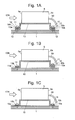
- Fig. 1A is a schematic configuration diagram showing an attachment structure for the ion detector in the mass spectrometer of the present embodiment.
- Fig. 1C is a schematic configuration diagram showing an attachment structure for the ion detector in a conventional mass spectrometer.
- ions enter the ion detector 5 from the left side as indicated by the arrows.
- the detection signal produced corresponding to the incident ions is extracted through the signal cable 59 extending from the ion detector 5 rightward. That is to say, the left surface of the ion detector 5 is the ion entrance surface 5a and the light surface is the detection-signal extraction surface 5b.
- a rigid attachment plate 10 is fixed to the bottom surface of the ion detector 5 in such a manner that the ion detector 5 and the attachment plate 10 constitute an integral structure.
- the flanges 10a which horizontally extend from the lower end of the attachment plate 10 have screw holes 10b.
- the attachment plate 10 is fixed to the inner surface of the vacuum chamber 1 with screws 11 passed through those screw holes 10b.
- the attachment plate 10 is fixed to the vacuum chamber 1 with screws 11 passed through the screw holes 10b directly or via washers or similar high-rigidity members (not shown) inserted in between. Accordingly, mechanical vibrations of the vacuum chamber 1 are directly transmitted via the attachment plate 10 to the ion detector 5
- the screw holes 10b bored in the flanges 10a of the attachment plate 10 are each sandwiched between a pair of ring-shaped cushioning members 12, and the attachment plate 10 is fixed to the inner surface of the vacuum chamber 1 by installing the screws 11 into the vacuum chamber 1 via the cushioning members 12.
- the cushioning members 12 almost entirely absorb mechanical vibrations of the vacuum chamber 1 and thereby suppress the vibration of the attachment plate 10 as well as that of the ion detector 5 integrally combined with this plate.
- the cushioning member 12 for example, an O-ring made of an elastic materials can be used.
- the cushioning member 12 should preferably be made of a material which barely releases gas.
- a Viton O-ring (“Viton” is a registered trademark of DuPont) or an equivalent product is suitable as the cushioning member 12.
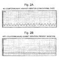
- Fig. 2A shows the waveform of a detection signal actually measured in the case where no countermeasure against vibration using the cushioning member 12 was taken
- Fig. 2B shows the waveform of a detection signal actually measured in the case where the countermeasure against vibration using the cushioning member 12 was taken as shown in Fig. 1A .
- the use of the cushioning member 12 is evidently effective in reducing the noise.
- ions passing through the quadrupole mass filter 4 i.e. ions which are to be detected with the ion detector 5 have the highest density in the vicinity of the ion beam axis C.
- the ion beam axis in the quadrupole mass filter 4 is the central axis of the arrangement of the four rod electrodes. Accordingly, in a system configured as shown in Figs.
- an attachment structure may be adopted as shown in Fig. 1B .
- the flange 10a located on the side of the ion entrance surface 5a through which ions enter is directly fixed to the vacuum chamber 1 with the screw 11 without the cushioning members 12 inserted in between. That is to say, it is fixed in the same manner as in Fig. 1C .
- the other flange 10a located on the side of the detection-signal extraction surface 5b from which the signal cable 59 is extracted is fixed to the vacuum chamber 1 with the screw 11 via the cushioning members 12 in the same manner as in Fig. 1A .
- the ion entrance surface 5a of the ion detector 5 vibrates in the same way as the vacuum chamber 1, while the vibration of the detection-signal extraction surface 5b is suppressed.
- the present structure is less effective in suppressing the vibration of the detection-signal extraction surface 5b.
- the vibration can be suppressed to such a level as to sufficiently reduce the noise if there is a certain distance between the ion entrance surface 5a and the detection-signal extraction surface 5b, i.e. if the ion detector 5 has an elongated shape.
- it is possible to reduce the noise without sacrificing the efficiency of introducing ions into the ion detector 5.
Landscapes
- Chemical & Material Sciences (AREA)
- Analytical Chemistry (AREA)
- Physics & Mathematics (AREA)
- Health & Medical Sciences (AREA)
- Life Sciences & Earth Sciences (AREA)
- General Physics & Mathematics (AREA)
- High Energy & Nuclear Physics (AREA)
- Molecular Biology (AREA)
- Spectroscopy & Molecular Physics (AREA)
- Electron Tubes For Measurement (AREA)
- Other Investigation Or Analysis Of Materials By Electrical Means (AREA)
Abstract
Description
- The present invention relates to a mass spectrometer, and more specifically, to the structure of a mass spectrometer.
- In general, mass spectrometers are configured so that ions generated from a sample component are separated according to their mass-to-charge ratios in a quadrupole mass filter or similar mass analyzer placed in a high-vacuum atmosphere and the separated ions are detected by an ion detector.
Fig. 3 is a schematic configuration diagram of a common type of quadrupole mass spectrometer. - An almost hermetically sealed
vacuum chamber 1 contains anEI ion source 2, anion lens 3, aquadrupole mass filter 4, anion detector 5 and other elements arranged along an ion beam axis C. When a gas containing a sample component is introduced into theEI ion source 2, the sample component comes in contact with thermions and is ionized. The generated ions are extracted from theEI ion source 2 and focused by theion lens 3, to be introduced into thequadrupole mass filter 4 consisting of four rod electrodes. A preset amount of voltage composed of a radio-frequency voltage superposed on a direct-current voltage is applied from a power source (not shown) to each of the rod electrodes of thequadrupole mass filter 4. Only an ion having a mass-to-charge ratio corresponding to the voltage passes through thequadrupole mass filter 4 and reaches theion detector 5. - As the
ion detector 5, a secondary electron multiplier (EPM) is commonly used (see Patent Literature 1).Fig. 4 is a schematic configuration diagram of anion detector 5 using a secondary electron multiplier. Each of the dynodes 51-56 arranged in a cascade structure is supplied with a preset amount of voltage from apower source 58. When an ion which has come from the left side on the figure and passed through theion entrance 50 collides with thefirst conversion dynode 51, secondary electrons are emitted, which are then accelerated by an electric field and made to collide with thesecond dynode 52, which in turn emits a larger amount of secondary electrons. Such a process is repeated at each of thediodes 53 ... arranged in the cascade form, with the result that the secondary electrons are eventually multiplied to a significantly large number. The secondary electrons thus multiplied are made to enter acollector 57, and an electric current thereby generated in thecollector 57 is extracted through asignal cable 59 as the detection signal. - To ensure high performance with the previously described mass spectrometer, it is necessary to maintain the inside of the
vacuum chamber 1 at the highest possible degree of vacuum. In many cases, this is achieved using a vacuum pump consisting of the combination of a high performance turbomolecular pump (TMP) and a rotary pump for decreasing the back pressure for the TMP (see Patent Literature 2). Normally, as shown inFig. 3 , theturbomolecular pump 6 is directly connected to thevacuum chamber 1 in order to efficiently evacuate this chamber, while therotary pump 7 is connected to theturbomolecular pump 6 via aconnecting tube 8. The primary reason for separating therotary pump 7 from thevacuum chamber 1 is to avoid internal contamination of thevacuum chamber 1 with the oil used in the rotary pump. By such a double-stage evacuation, the inside of thevacuum chamber 1 is maintained at low gas pressure (high degree of vacuum) within a range from 10-3 to 10-4 Pa. - As is commonly known, turbomolecular pumps perform evacuation in molecular units through interaction between moving blades (which are formed on a rotor rotated at high speeds) and stationary blades. Since the rotor is rotated at high speeds of up to several ten thousand rpm, turbomolecular pumps normally cause significant vibrations. In a system having a configuration as shown in
Fig. 3 , this mechanical vibration of theturbomolecular pump 6 is directly transmitted to thevacuum chamber 1, causing the various parts fixed to thevacuum chamber 1 to vibrate. Theion detector 5 is also one of the parts fixed to thevacuum chamber 1, which means that the mechanical vibration of thevacuum chamber 1 is also transmitted to theion detector 5. The transmitted vibration may cause a noise in the detection signal extracted from theion detector 5. - The primary reason for this noise is probably the vibration of a signal line (signal cable) extracted from the ion detector 5: When the signal line vibrates, the distance between the outer surface of the signal line and the
vacuum chamber 1 or other surrounding members slightly changes, which causes a fluctuation in the impedance of the signal line. Since the preamplifier for amplifying detection signals from theion detector 5 has a high input impedance, the fluctuation in the impedance of the signal line can easily appear as a noise. The frequency of the noise superposed on the detection signal due to the mechanical vibration of the turbomolecular pump is within a range from several hundred Hz through several kHz, which in some cases overlaps the frequency of the signal obtained by mass spectrometry. Therefore, it is difficult to electrically remove this noise using a filter or similar devices. -
- Patent Literature 1:
JP 2000-357487 A - Patent Literature 2:
JP 2003-346702 A - The present invention has been developed to solve the previously described problem. Its objective is to provide a mass spectrometer capable of performing an analysis with high accuracy by suppressing the noise superposed on the detection signal due to the mechanical vibration of a turbomolecular pump or similar vacuum pump.
- The present invention aimed at solving the previously described problem is a mass spectrometer in which a mass analyzer for mass-separating ions to be analyzed and a detector for detecting the mass-separated ions are provided inside a vacuum chamber configured to be evacuated by a vacuum pump, characterized in that:
- the detector is fixed to the vacuum chamber via a cushioning member.
- The vacuum pump typically includes a turbomolecular pump and has a configuration in which the turbomolecular pump is attached to an outer surface of the vacuum chamber. Such a configuration allows the mechanical vibration of the turbomolecular pump to be directly transmitted to the vacuum chamber. The cushioning member absorbs the vibration from the vacuum chamber, whereby the vibration of the detector itself is suppressed. As a result, the noise resulting from the vibration and being superposed on the detection signal from the detector is reduced.
- In one preferable mode of the mass spectrometer according to the present invention, an attachment part on an ion entrance side of the detector is fixed to the vacuum chamber without the cushioning member inserted in between while an attachment part on a detection-signal extraction side of the detector is fixed to the vacuum chamber via the cushioning member.
- The ion entrance of the detector is an opening through which ions selected by the mass analyzer in the previous stage enter the detector. For example, if the mass analyzer is a quadrupole mass filter, the ions passing through the mass filter have the highest density in the vicinity of the central axis of the mass filter. Therefore, to efficiently introduce the ions into the detector, the central axis of the quadrupole mass filter should preferably be made to coincide with that of the ion entrance part of the detector.
- If the quadrupole mass filter is fixed to the vacuum chamber, and if the attachment part on the ion entrance side of the detector is also fixed to the vacuum chamber as in the previously described mode, both the quadrupole mass filter and the ion entrance part of the detector vibrate in almost the same way when the vacuum chamber vibrates. Therefore, if the quadrupole mass filter and the ion entrance part of the detector are arranged so that their central axes coincide with each other, the coincidence of the two central axes will be maintained even when the vibration due to the vacuum pump occurs. Accordingly, the ions which have passed through the quadrupole mass filter can be efficiently introduced into the detector.
- On the other hand, the attachment part on the detection-signal extraction side of the detector is fixed to the vacuum chamber via the cushioning member. Therefore, the vibration of the attachment part on the detection-signal extraction part of the detector is adequately suppressed as compared to the case where no cushioning member is provided. Therefore, the signal line extracted from the detector barely vibrates, and the noise due to this vibration is less likely to occur.
- In the case where the ion entrance part and the detection-signal extraction part are closely located to each other in the detector, it is difficult to suppress the vibration of the detection-signal extraction part without providing the cushioning member at the attachment part on the ion entrance side. In general, a detector including a secondary electron multiplier has a considerable distance between the ion entrance part and the detection-signal extraction part since the secondary electron multiplier includes a cascade system of dynodes. Therefore, the previously described mode of the invention is particularly effective when applied in a system which employs a detector including a secondary electron multiplier.
- In the mass spectrometer according to the present invention, the noise superposed on the detection signal due to the mechanical vibration of the vacuum pump is reduced by a simple and inexpensive configuration. As a result, for example, the mass accuracy and the detection sensitivity will be improved.
-
-
Figs. 1A and 1B are schematic diagrams showing attachment structures for a detector in one embodiment of the mass spectrometer according to the present invention, whileFig. 1C shows an attachment structure for a detector in a conventional mass spectrometer. -
Figs. 2A and 2B are actually measured waveform diagrams showing the noise suppression effect by the mass spectrometer of the present embodiment. -
Fig. 3 is a schematic configuration diagram of a common type of quadrupole mass spectrometer. -
Fig. 4 is a schematic configuration diagram showing one example of the ion detector shown inFig. 3 . - One embodiment of the mass spectrometer according to the present invention is hereinafter described with reference to the attached drawings. The overall configuration of the mass spectrometer of the present embodiment is the same as that of the conventionally used common type of quadrupole mass spectrometer shown in
Fig. 3 and hence will not be described. The configuration of the ion detector itself is also the same as that of the conventional ion detector shown inFig. 4 and hence will not be described. -
Fig. 1A is a schematic configuration diagram showing an attachment structure for the ion detector in the mass spectrometer of the present embodiment.Fig. 1C is a schematic configuration diagram showing an attachment structure for the ion detector in a conventional mass spectrometer. In those figures, ions enter theion detector 5 from the left side as indicated by the arrows. The detection signal produced corresponding to the incident ions is extracted through thesignal cable 59 extending from theion detector 5 rightward. That is to say, the left surface of theion detector 5 is theion entrance surface 5a and the light surface is the detection-signal extraction surface 5b. - A
rigid attachment plate 10 is fixed to the bottom surface of theion detector 5 in such a manner that theion detector 5 and theattachment plate 10 constitute an integral structure. Theflanges 10a which horizontally extend from the lower end of theattachment plate 10 havescrew holes 10b. Theattachment plate 10 is fixed to the inner surface of thevacuum chamber 1 withscrews 11 passed through thosescrew holes 10b. In the conventional case, as shown inFig. 1C , theattachment plate 10 is fixed to thevacuum chamber 1 withscrews 11 passed through the screw holes 10b directly or via washers or similar high-rigidity members (not shown) inserted in between. Accordingly, mechanical vibrations of thevacuum chamber 1 are directly transmitted via theattachment plate 10 to theion detector 5 - By contrast, in the mass spectrometer according to the present embodiment, as shown in
Fig. 1A , the screw holes 10b bored in theflanges 10a of theattachment plate 10 are each sandwiched between a pair of ring-shapedcushioning members 12, and theattachment plate 10 is fixed to the inner surface of thevacuum chamber 1 by installing thescrews 11 into thevacuum chamber 1 via thecushioning members 12. Thecushioning members 12 almost entirely absorb mechanical vibrations of thevacuum chamber 1 and thereby suppress the vibration of theattachment plate 10 as well as that of theion detector 5 integrally combined with this plate. - As the ling-shaped
cushioning member 12, for example, an O-ring made of an elastic materials can be used. To avoid the situation where unwanted gas is emitted from the cushioningmember 12 and contaminates the inside of thevacuum chamber 1, the cushioningmember 12 should preferably be made of a material which barely releases gas. As a specific example, a Viton O-ring ("Viton" is a registered trademark of DuPont) or an equivalent product is suitable as the cushioningmember 12. -
Fig. 2A shows the waveform of a detection signal actually measured in the case where no countermeasure against vibration using the cushioningmember 12 was taken, andFig. 2B shows the waveform of a detection signal actually measured in the case where the countermeasure against vibration using the cushioningmember 12 was taken as shown inFig. 1A . The use of the cushioningmember 12 is evidently effective in reducing the noise. These results demonstrate that the noise superposed on the detection signal can be adequately suppressed by taking the previously described simple countermeasure against vibration. - In the example of
Fig. 1A , all theflanges 10a of theattachment plate 10 are in contact with the inner surface of thevacuum chamber 1 via thecushioning members 12. This configuration produces a high level of vibration-suppressing effect but has the following problem: As shown inFig. 3 , ions passing through the quadrupolemass filter 4, i.e. ions which are to be detected with theion detector 5, have the highest density in the vicinity of the ion beam axis C. The ion beam axis in the quadrupolemass filter 4 is the central axis of the arrangement of the four rod electrodes. Accordingly, in a system configured as shown inFigs. 3 and 4 , it is necessary to make the central axis of the quadrupolemass filter 4 coincide with that of theion entrance 50 of theion detector 5 so as to efficiently introduce the ions into theion detector 5, and the arrangement of the members concerned are adjusted to satisfy this requirement. - Even if the
vacuum chamber 1 vibrates, the coincidence of the two aforementioned central axes will be maintained if the quadrupolemass filter 4 and theion detector 5 vibrate in the same way (or if none of them vibrates). By contrast, if the vibration of theion detector 5 is suppressed in the previously described manner due to the effect of thecushioning members 12 while the quadrupolemass filter 4 fixed to thevacuum chamber 1 vibrates, the coincidence of the central axes is less likely to be maintained. On the other hand, suppressing the vibration of thesignal cable 59 extracted from theion detector 5 is necessary in order to reduce the noise. - To address this problem, an attachment structure according to another embodiment of the present invention may be adopted as shown in
Fig. 1B . In this example, theflange 10a located on the side of theion entrance surface 5a through which ions enter is directly fixed to thevacuum chamber 1 with thescrew 11 without thecushioning members 12 inserted in between. That is to say, it is fixed in the same manner as inFig. 1C . On the other hand, theother flange 10a located on the side of the detection-signal extraction surface 5b from which thesignal cable 59 is extracted is fixed to thevacuum chamber 1 with thescrew 11 via thecushioning members 12 in the same manner as inFig. 1A . According to this configuration, when thevacuum chamber 1 vibrates, theion entrance surface 5a of theion detector 5 vibrates in the same way as thevacuum chamber 1, while the vibration of the detection-signal extraction surface 5b is suppressed. - Naturally, as compared to the structure of
Fig. 1A , the present structure is less effective in suppressing the vibration of the detection-signal extraction surface 5b. However, the vibration can be suppressed to such a level as to sufficiently reduce the noise if there is a certain distance between theion entrance surface 5a and the detection-signal extraction surface 5b, i.e. if theion detector 5 has an elongated shape. Thus, it is possible to reduce the noise without sacrificing the efficiency of introducing ions into theion detector 5. - It should be noted that the previous embodiment is a mere example of the present invention, and any change, addition or modification appropriately made within the spirit of the present invention will evidently fall within the scope of claims of the present patent application.
-
- 1
- Vacuum Chamber
- 2
- EI Ion Source
- 3
- Ion Lens
- 4
- Quadrupole Mass Filter
- 5
- Ion Detector
- 50
- Ion Entrance
- 51
- Conversion Dynode
- 52-56
- Dynode
- 57
- Collector
- 58
- Power Source
- 59
- Signal Cable
- 5a
- Ion Entrance Surface
- 5b
- Detection-Signal Extraction Surface
- 6
- Turbomolecular Pump
- 7
- Rotary Pump
- 8
- Connecting Tube
- 10
- Attachment Plate
- 10a
- Flange
- 10b
- Screw Hole
- 11
- Screw
- 12
- Cushioning Member
- C
- Ion Beam Axis
Claims (3)
- A mass spectrometer comprising:a mass analyzer for mass-separating ions to be analyzed provided inside a vacuum chamber configured to be evacuated by a vacuum pump; anda detector for detecting the mass-separated ions provided inside the vacuum chamber,wherein:the detector is fixed to the vacuum chamber via a cushioning member.
- The mass spectrometer according to claim 1, wherein:an attachment part on an ion entrance side of the detector is fixed to the vacuum chamber without the cushioning member inserted in between while an attachment part on a detection-signal extraction side of the detector is fixed to the vacuum chamber via the cushioning member.
- The mass spectrometer according to claim 2, wherein:the detector includes a secondary electron multiplier.
Applications Claiming Priority (1)
| Application Number | Priority Date | Filing Date | Title |
|---|---|---|---|
| PCT/JP2012/061711 WO2013168220A1 (en) | 2012-05-08 | 2012-05-08 | Mass spectrometer |
Publications (2)
| Publication Number | Publication Date |
|---|---|
| EP2849205A1 true EP2849205A1 (en) | 2015-03-18 |
| EP2849205A4 EP2849205A4 (en) | 2015-04-29 |
Family
ID=49550305
Family Applications (1)
| Application Number | Title | Priority Date | Filing Date |
|---|---|---|---|
| EP12876541.9A Withdrawn EP2849205A4 (en) | 2012-05-08 | 2012-05-08 | Mass spectrometer |
Country Status (4)
| Country | Link |
|---|---|
| US (1) | US9312115B2 (en) |
| EP (1) | EP2849205A4 (en) |
| JP (1) | JP5861775B2 (en) |
| WO (1) | WO2013168220A1 (en) |
Families Citing this family (5)
| Publication number | Priority date | Publication date | Assignee | Title |
|---|---|---|---|---|
| US9449805B2 (en) * | 2014-09-23 | 2016-09-20 | Agilent Technologies Inc. | Isolation of charged particle optics from vacuum chamber deformations |
| US11493383B2 (en) | 2019-02-17 | 2022-11-08 | .El-Mul Technologies Ltd | Magnetic photomultiplier tube system |
| US11587776B1 (en) * | 2019-05-30 | 2023-02-21 | El-Mul Technologies Ltd | Ion detection systems |
| US11656371B1 (en) | 2020-06-09 | 2023-05-23 | El-Mul Technologies Ltd | High dynamic range detector with controllable photon flux functionality |
| WO2023058248A1 (en) * | 2021-10-08 | 2023-04-13 | 株式会社島津製作所 | Mass analysis device |
Family Cites Families (16)
| Publication number | Priority date | Publication date | Assignee | Title |
|---|---|---|---|---|
| JPS5225293B2 (en) * | 1973-10-17 | 1977-07-06 | ||
| JPS5467489A (en) * | 1977-11-09 | 1979-05-30 | Hitachi Ltd | Ion detector for mass analyzer |
| JPS5834044U (en) * | 1981-08-29 | 1983-03-05 | 株式会社島津製作所 | Electron multiplier tube mounting structure in analyzer |
| JPS6179450U (en) * | 1984-10-31 | 1986-05-27 | ||
| DE3510378A1 (en) * | 1985-03-22 | 1986-10-02 | Coulston International Corp., Albany, N.Y. | METHOD FOR THE ANALYTICAL DETERMINATION OF ORGANIC SUBSTANCES |
| JPS6244946A (en) * | 1985-08-22 | 1987-02-26 | Shimadzu Corp | Detector for charged particles, etc. |
| JPH0877962A (en) * | 1994-08-31 | 1996-03-22 | Shimadzu Corp | Mass spectrometer |
| US5998215A (en) * | 1995-05-01 | 1999-12-07 | The Regents Of The University Of California | Portable analyzer for determining size and chemical composition of an aerosol |
| JP3544884B2 (en) * | 1999-02-25 | 2004-07-21 | 株式会社東芝 | Charged particle beam irradiation device |
| JP2000357487A (en) | 1999-06-14 | 2000-12-26 | Shimadzu Corp | Mass spectrometer |
| US6242748B1 (en) | 1999-08-10 | 2001-06-05 | Edax, Inc. | Methods and apparatus for mounting an X-ray detecting unit to an electron microscope |
| JP3890883B2 (en) * | 2000-12-04 | 2007-03-07 | 株式会社島津製作所 | Energy dispersive X-ray detector, scanning electron microscope and electron microanalyzer using the same |
| JP3758606B2 (en) | 2002-05-22 | 2006-03-22 | 株式会社島津製作所 | Vacuum analyzer |
| WO2006041567A2 (en) * | 2004-08-16 | 2006-04-20 | Oi Corporation | Optical bench for a mass spectrometer system |
| JP5210940B2 (en) * | 2009-03-31 | 2013-06-12 | 浜松ホトニクス株式会社 | Mass spectrometer |
| JP2012003946A (en) * | 2010-06-17 | 2012-01-05 | Shimadzu Corp | Time-of-flight mass spectrometer |
-
2012
- 2012-05-08 JP JP2014514250A patent/JP5861775B2/en active Active
- 2012-05-08 US US14/391,800 patent/US9312115B2/en active Active
- 2012-05-08 EP EP12876541.9A patent/EP2849205A4/en not_active Withdrawn
- 2012-05-08 WO PCT/JP2012/061711 patent/WO2013168220A1/en not_active Ceased
Also Published As
| Publication number | Publication date |
|---|---|
| US20150262806A1 (en) | 2015-09-17 |
| JP5861775B2 (en) | 2016-02-16 |
| EP2849205A4 (en) | 2015-04-29 |
| JPWO2013168220A1 (en) | 2015-12-24 |
| WO2013168220A1 (en) | 2013-11-14 |
| US9312115B2 (en) | 2016-04-12 |
Similar Documents
| Publication | Publication Date | Title |
|---|---|---|
| US8796616B2 (en) | Miniature mass spectrometer system | |
| US5504328A (en) | Endpoint detection utilizing ultraviolet mass spectrometry | |
| US9312115B2 (en) | Mass spectrometer | |
| JP4931793B2 (en) | Mass spectrometer focal plane detector assembly | |
| JP5539801B2 (en) | Gas sampling device and gas analyzer using the same | |
| CN101281165A (en) | Ionization method and device for mass spectrometry sample | |
| US9177775B2 (en) | Mass spectrometer | |
| CN112166255B (en) | Desk type time-of-flight mass spectrometer | |
| GB2302984A (en) | Ion trap mass spectrometer | |
| JP2018073703A (en) | Mass spectrometer | |
| US10410849B2 (en) | Multipole ion guide | |
| JP6593451B2 (en) | Quadrupole mass filter and quadrupole mass spectrometer | |
| CN114141601B (en) | Long life electron multiplier | |
| JP2010177120A (en) | Ion detector and quadrupole mass spectrometer equipped with the same, and faraday cup | |
| CN112868085A (en) | Ion detector | |
| CN105428199B (en) | Mass spectrometric analysis method and the mass spectrometer with atmospheric pressure interface | |
| JP2010027622A (en) | Mass spectroscope | |
| KR102587356B1 (en) | Differential vacuum ionization source | |
| CN205542700U (en) | Electron bombardment source and mass spectrograph | |
| CN114121592B (en) | Vacuum light source | |
| US11536604B1 (en) | Light sensor assembly in a vacuum environment | |
| WO2018138838A1 (en) | Mass spectrometry method and mass spectrometry device | |
| KR101914881B1 (en) | Small type time of flight mass spectrometer | |
| WO2022024398A1 (en) | Ion trap and mass spectrometer | |
| WO2022024397A1 (en) | Ion trap device and mass spectrometry device |
Legal Events
| Date | Code | Title | Description |
|---|---|---|---|
| PUAI | Public reference made under article 153(3) epc to a published international application that has entered the european phase |
Free format text: ORIGINAL CODE: 0009012 |
|
| 17P | Request for examination filed |
Effective date: 20141023 |
|
| AK | Designated contracting states |
Kind code of ref document: A1 Designated state(s): AL AT BE BG CH CY CZ DE DK EE ES FI FR GB GR HR HU IE IS IT LI LT LU LV MC MK MT NL NO PL PT RO RS SE SI SK SM TR |
|
| AX | Request for extension of the european patent |
Extension state: BA ME |
|
| RA4 | Supplementary search report drawn up and despatched (corrected) |
Effective date: 20150326 |
|
| RIC1 | Information provided on ipc code assigned before grant |
Ipc: H01J 49/02 20060101AFI20150320BHEP Ipc: H01J 49/06 20060101ALN20150320BHEP Ipc: H01J 49/26 20060101ALI20150320BHEP |
|
| DAX | Request for extension of the european patent (deleted) | ||
| 17Q | First examination report despatched |
Effective date: 20180411 |
|
| GRAP | Despatch of communication of intention to grant a patent |
Free format text: ORIGINAL CODE: EPIDOSNIGR1 |
|
| RIC1 | Information provided on ipc code assigned before grant |
Ipc: H01J 49/02 20060101AFI20190516BHEP |
|
| INTG | Intention to grant announced |
Effective date: 20190613 |
|
| STAA | Information on the status of an ep patent application or granted ep patent |
Free format text: STATUS: THE APPLICATION IS DEEMED TO BE WITHDRAWN |
|
| 18D | Application deemed to be withdrawn |
Effective date: 20191024 |