EP2848448A2 - Fahrzeug mit Elektroantrieb und einer Anzeigevorrichtung zur Anzeige eines Betriebszustandes eines Energiespeichers des Elektroantriebs - Google Patents
Fahrzeug mit Elektroantrieb und einer Anzeigevorrichtung zur Anzeige eines Betriebszustandes eines Energiespeichers des Elektroantriebs Download PDFInfo
- Publication number
- EP2848448A2 EP2848448A2 EP14001059.6A EP14001059A EP2848448A2 EP 2848448 A2 EP2848448 A2 EP 2848448A2 EP 14001059 A EP14001059 A EP 14001059A EP 2848448 A2 EP2848448 A2 EP 2848448A2
- Authority
- EP
- European Patent Office
- Prior art keywords
- vehicle
- display device
- electric drive
- vehicle according
- display
- Prior art date
- Legal status (The legal status is an assumption and is not a legal conclusion. Google has not performed a legal analysis and makes no representation as to the accuracy of the status listed.)
- Granted
Links
Images

Classifications
-
- B—PERFORMING OPERATIONS; TRANSPORTING
- B60—VEHICLES IN GENERAL
- B60L—PROPULSION OF ELECTRICALLY-PROPELLED VEHICLES; SUPPLYING ELECTRIC POWER FOR AUXILIARY EQUIPMENT OF ELECTRICALLY-PROPELLED VEHICLES; ELECTRODYNAMIC BRAKE SYSTEMS FOR VEHICLES IN GENERAL; MAGNETIC SUSPENSION OR LEVITATION FOR VEHICLES; MONITORING OPERATING VARIABLES OF ELECTRICALLY-PROPELLED VEHICLES; ELECTRIC SAFETY DEVICES FOR ELECTRICALLY-PROPELLED VEHICLES
- B60L3/00—Electric devices on electrically-propelled vehicles for safety purposes; Monitoring operating variables, e.g. speed, deceleration or energy consumption
- B60L3/0023—Detecting, eliminating, remedying or compensating for drive train abnormalities, e.g. failures within the drive train
-
- B—PERFORMING OPERATIONS; TRANSPORTING
- B60—VEHICLES IN GENERAL
- B60L—PROPULSION OF ELECTRICALLY-PROPELLED VEHICLES; SUPPLYING ELECTRIC POWER FOR AUXILIARY EQUIPMENT OF ELECTRICALLY-PROPELLED VEHICLES; ELECTRODYNAMIC BRAKE SYSTEMS FOR VEHICLES IN GENERAL; MAGNETIC SUSPENSION OR LEVITATION FOR VEHICLES; MONITORING OPERATING VARIABLES OF ELECTRICALLY-PROPELLED VEHICLES; ELECTRIC SAFETY DEVICES FOR ELECTRICALLY-PROPELLED VEHICLES
- B60L53/00—Methods of charging batteries, specially adapted for electric vehicles; Charging stations or on-board charging equipment therefor; Exchange of energy storage elements in electric vehicles
- B60L53/10—Methods of charging batteries, specially adapted for electric vehicles; Charging stations or on-board charging equipment therefor; Exchange of energy storage elements in electric vehicles characterised by the energy transfer between the charging station and the vehicle
- B60L53/14—Conductive energy transfer
-
- B—PERFORMING OPERATIONS; TRANSPORTING
- B60—VEHICLES IN GENERAL
- B60K—ARRANGEMENT OR MOUNTING OF PROPULSION UNITS OR OF TRANSMISSIONS IN VEHICLES; ARRANGEMENT OR MOUNTING OF PLURAL DIVERSE PRIME-MOVERS IN VEHICLES; AUXILIARY DRIVES FOR VEHICLES; INSTRUMENTATION OR DASHBOARDS FOR VEHICLES; ARRANGEMENTS IN CONNECTION WITH COOLING, AIR INTAKE, GAS EXHAUST OR FUEL SUPPLY OF PROPULSION UNITS IN VEHICLES
- B60K35/00—Instruments specially adapted for vehicles; Arrangement of instruments in or on vehicles
- B60K35/20—Output arrangements, i.e. from vehicle to user, associated with vehicle functions or specially adapted therefor
- B60K35/21—Output arrangements, i.e. from vehicle to user, associated with vehicle functions or specially adapted therefor using visual output, e.g. blinking lights or matrix displays
-
- B—PERFORMING OPERATIONS; TRANSPORTING
- B60—VEHICLES IN GENERAL
- B60K—ARRANGEMENT OR MOUNTING OF PROPULSION UNITS OR OF TRANSMISSIONS IN VEHICLES; ARRANGEMENT OR MOUNTING OF PLURAL DIVERSE PRIME-MOVERS IN VEHICLES; AUXILIARY DRIVES FOR VEHICLES; INSTRUMENTATION OR DASHBOARDS FOR VEHICLES; ARRANGEMENTS IN CONNECTION WITH COOLING, AIR INTAKE, GAS EXHAUST OR FUEL SUPPLY OF PROPULSION UNITS IN VEHICLES
- B60K35/00—Instruments specially adapted for vehicles; Arrangement of instruments in or on vehicles
- B60K35/20—Output arrangements, i.e. from vehicle to user, associated with vehicle functions or specially adapted therefor
- B60K35/28—Output arrangements, i.e. from vehicle to user, associated with vehicle functions or specially adapted therefor characterised by the type of the output information, e.g. video entertainment or vehicle dynamics information; characterised by the purpose of the output information, e.g. for attracting the attention of the driver
-
- B—PERFORMING OPERATIONS; TRANSPORTING
- B60—VEHICLES IN GENERAL
- B60K—ARRANGEMENT OR MOUNTING OF PROPULSION UNITS OR OF TRANSMISSIONS IN VEHICLES; ARRANGEMENT OR MOUNTING OF PLURAL DIVERSE PRIME-MOVERS IN VEHICLES; AUXILIARY DRIVES FOR VEHICLES; INSTRUMENTATION OR DASHBOARDS FOR VEHICLES; ARRANGEMENTS IN CONNECTION WITH COOLING, AIR INTAKE, GAS EXHAUST OR FUEL SUPPLY OF PROPULSION UNITS IN VEHICLES
- B60K35/00—Instruments specially adapted for vehicles; Arrangement of instruments in or on vehicles
- B60K35/20—Output arrangements, i.e. from vehicle to user, associated with vehicle functions or specially adapted therefor
- B60K35/29—Instruments characterised by the way in which information is handled, e.g. showing information on plural displays or prioritising information according to driving conditions
-
- B—PERFORMING OPERATIONS; TRANSPORTING
- B60—VEHICLES IN GENERAL
- B60K—ARRANGEMENT OR MOUNTING OF PROPULSION UNITS OR OF TRANSMISSIONS IN VEHICLES; ARRANGEMENT OR MOUNTING OF PLURAL DIVERSE PRIME-MOVERS IN VEHICLES; AUXILIARY DRIVES FOR VEHICLES; INSTRUMENTATION OR DASHBOARDS FOR VEHICLES; ARRANGEMENTS IN CONNECTION WITH COOLING, AIR INTAKE, GAS EXHAUST OR FUEL SUPPLY OF PROPULSION UNITS IN VEHICLES
- B60K35/00—Instruments specially adapted for vehicles; Arrangement of instruments in or on vehicles
- B60K35/60—Instruments characterised by their location or relative disposition in or on vehicles
-
- B—PERFORMING OPERATIONS; TRANSPORTING
- B60—VEHICLES IN GENERAL
- B60L—PROPULSION OF ELECTRICALLY-PROPELLED VEHICLES; SUPPLYING ELECTRIC POWER FOR AUXILIARY EQUIPMENT OF ELECTRICALLY-PROPELLED VEHICLES; ELECTRODYNAMIC BRAKE SYSTEMS FOR VEHICLES IN GENERAL; MAGNETIC SUSPENSION OR LEVITATION FOR VEHICLES; MONITORING OPERATING VARIABLES OF ELECTRICALLY-PROPELLED VEHICLES; ELECTRIC SAFETY DEVICES FOR ELECTRICALLY-PROPELLED VEHICLES
- B60L3/00—Electric devices on electrically-propelled vehicles for safety purposes; Monitoring operating variables, e.g. speed, deceleration or energy consumption
- B60L3/0023—Detecting, eliminating, remedying or compensating for drive train abnormalities, e.g. failures within the drive train
- B60L3/0069—Detecting, eliminating, remedying or compensating for drive train abnormalities, e.g. failures within the drive train relating to the isolation, e.g. ground fault or leak current
-
- B—PERFORMING OPERATIONS; TRANSPORTING
- B60—VEHICLES IN GENERAL
- B60L—PROPULSION OF ELECTRICALLY-PROPELLED VEHICLES; SUPPLYING ELECTRIC POWER FOR AUXILIARY EQUIPMENT OF ELECTRICALLY-PROPELLED VEHICLES; ELECTRODYNAMIC BRAKE SYSTEMS FOR VEHICLES IN GENERAL; MAGNETIC SUSPENSION OR LEVITATION FOR VEHICLES; MONITORING OPERATING VARIABLES OF ELECTRICALLY-PROPELLED VEHICLES; ELECTRIC SAFETY DEVICES FOR ELECTRICALLY-PROPELLED VEHICLES
- B60L3/00—Electric devices on electrically-propelled vehicles for safety purposes; Monitoring operating variables, e.g. speed, deceleration or energy consumption
- B60L3/12—Recording operating variables ; Monitoring of operating variables
-
- B—PERFORMING OPERATIONS; TRANSPORTING
- B60—VEHICLES IN GENERAL
- B60L—PROPULSION OF ELECTRICALLY-PROPELLED VEHICLES; SUPPLYING ELECTRIC POWER FOR AUXILIARY EQUIPMENT OF ELECTRICALLY-PROPELLED VEHICLES; ELECTRODYNAMIC BRAKE SYSTEMS FOR VEHICLES IN GENERAL; MAGNETIC SUSPENSION OR LEVITATION FOR VEHICLES; MONITORING OPERATING VARIABLES OF ELECTRICALLY-PROPELLED VEHICLES; ELECTRIC SAFETY DEVICES FOR ELECTRICALLY-PROPELLED VEHICLES
- B60L50/00—Electric propulsion with power supplied within the vehicle
- B60L50/40—Electric propulsion with power supplied within the vehicle using propulsion power supplied by capacitors
-
- B—PERFORMING OPERATIONS; TRANSPORTING
- B60—VEHICLES IN GENERAL
- B60L—PROPULSION OF ELECTRICALLY-PROPELLED VEHICLES; SUPPLYING ELECTRIC POWER FOR AUXILIARY EQUIPMENT OF ELECTRICALLY-PROPELLED VEHICLES; ELECTRODYNAMIC BRAKE SYSTEMS FOR VEHICLES IN GENERAL; MAGNETIC SUSPENSION OR LEVITATION FOR VEHICLES; MONITORING OPERATING VARIABLES OF ELECTRICALLY-PROPELLED VEHICLES; ELECTRIC SAFETY DEVICES FOR ELECTRICALLY-PROPELLED VEHICLES
- B60L50/00—Electric propulsion with power supplied within the vehicle
- B60L50/50—Electric propulsion with power supplied within the vehicle using propulsion power supplied by batteries or fuel cells
- B60L50/60—Electric propulsion with power supplied within the vehicle using propulsion power supplied by batteries or fuel cells using power supplied by batteries
- B60L50/66—Arrangements of batteries
-
- B—PERFORMING OPERATIONS; TRANSPORTING
- B60—VEHICLES IN GENERAL
- B60L—PROPULSION OF ELECTRICALLY-PROPELLED VEHICLES; SUPPLYING ELECTRIC POWER FOR AUXILIARY EQUIPMENT OF ELECTRICALLY-PROPELLED VEHICLES; ELECTRODYNAMIC BRAKE SYSTEMS FOR VEHICLES IN GENERAL; MAGNETIC SUSPENSION OR LEVITATION FOR VEHICLES; MONITORING OPERATING VARIABLES OF ELECTRICALLY-PROPELLED VEHICLES; ELECTRIC SAFETY DEVICES FOR ELECTRICALLY-PROPELLED VEHICLES
- B60L58/00—Methods or circuit arrangements for monitoring or controlling batteries or fuel cells, specially adapted for electric vehicles
- B60L58/10—Methods or circuit arrangements for monitoring or controlling batteries or fuel cells, specially adapted for electric vehicles for monitoring or controlling batteries
- B60L58/12—Methods or circuit arrangements for monitoring or controlling batteries or fuel cells, specially adapted for electric vehicles for monitoring or controlling batteries responding to state of charge [SoC]
-
- B—PERFORMING OPERATIONS; TRANSPORTING
- B60—VEHICLES IN GENERAL
- B60Q—ARRANGEMENT OF SIGNALLING OR LIGHTING DEVICES, THE MOUNTING OR SUPPORTING THEREOF OR CIRCUITS THEREFOR, FOR VEHICLES IN GENERAL
- B60Q1/00—Arrangement of optical signalling or lighting devices, the mounting or supporting thereof or circuits therefor
- B60Q1/0029—Spatial arrangement
- B60Q1/0035—Spatial arrangement relative to the vehicle
-
- B—PERFORMING OPERATIONS; TRANSPORTING
- B60—VEHICLES IN GENERAL
- B60Q—ARRANGEMENT OF SIGNALLING OR LIGHTING DEVICES, THE MOUNTING OR SUPPORTING THEREOF OR CIRCUITS THEREFOR, FOR VEHICLES IN GENERAL
- B60Q1/00—Arrangement of optical signalling or lighting devices, the mounting or supporting thereof or circuits therefor
- B60Q1/26—Arrangement of optical signalling or lighting devices, the mounting or supporting thereof or circuits therefor the devices being primarily intended to indicate the vehicle, or parts thereof, or to give signals, to other traffic
- B60Q1/50—Arrangement of optical signalling or lighting devices, the mounting or supporting thereof or circuits therefor the devices being primarily intended to indicate the vehicle, or parts thereof, or to give signals, to other traffic for indicating other intentions or conditions, e.g. request for waiting or overtaking
- B60Q1/543—Arrangement of optical signalling or lighting devices, the mounting or supporting thereof or circuits therefor the devices being primarily intended to indicate the vehicle, or parts thereof, or to give signals, to other traffic for indicating other intentions or conditions, e.g. request for waiting or overtaking for indicating other states or conditions of the vehicle
-
- G—PHYSICS
- G01—MEASURING; TESTING
- G01R—MEASURING ELECTRIC VARIABLES; MEASURING MAGNETIC VARIABLES
- G01R31/00—Arrangements for testing electric properties; Arrangements for locating electric faults; Arrangements for electrical testing characterised by what is being tested not provided for elsewhere
- G01R31/36—Arrangements for testing, measuring or monitoring the electrical condition of accumulators or electric batteries, e.g. capacity or state of charge [SoC]
- G01R31/371—Arrangements for testing, measuring or monitoring the electrical condition of accumulators or electric batteries, e.g. capacity or state of charge [SoC] with remote indication, e.g. on external chargers
-
- B—PERFORMING OPERATIONS; TRANSPORTING
- B60—VEHICLES IN GENERAL
- B60K—ARRANGEMENT OR MOUNTING OF PROPULSION UNITS OR OF TRANSMISSIONS IN VEHICLES; ARRANGEMENT OR MOUNTING OF PLURAL DIVERSE PRIME-MOVERS IN VEHICLES; AUXILIARY DRIVES FOR VEHICLES; INSTRUMENTATION OR DASHBOARDS FOR VEHICLES; ARRANGEMENTS IN CONNECTION WITH COOLING, AIR INTAKE, GAS EXHAUST OR FUEL SUPPLY OF PROPULSION UNITS IN VEHICLES
- B60K2360/00—Indexing scheme associated with groups B60K35/00 or B60K37/00 relating to details of instruments or dashboards
- B60K2360/16—Type of output information
- B60K2360/169—Remaining operating distance or charge
-
- B—PERFORMING OPERATIONS; TRANSPORTING
- B60—VEHICLES IN GENERAL
- B60K—ARRANGEMENT OR MOUNTING OF PROPULSION UNITS OR OF TRANSMISSIONS IN VEHICLES; ARRANGEMENT OR MOUNTING OF PLURAL DIVERSE PRIME-MOVERS IN VEHICLES; AUXILIARY DRIVES FOR VEHICLES; INSTRUMENTATION OR DASHBOARDS FOR VEHICLES; ARRANGEMENTS IN CONNECTION WITH COOLING, AIR INTAKE, GAS EXHAUST OR FUEL SUPPLY OF PROPULSION UNITS IN VEHICLES
- B60K2360/00—Indexing scheme associated with groups B60K35/00 or B60K37/00 relating to details of instruments or dashboards
- B60K2360/16—Type of output information
- B60K2360/174—Economic driving
-
- B—PERFORMING OPERATIONS; TRANSPORTING
- B60—VEHICLES IN GENERAL
- B60K—ARRANGEMENT OR MOUNTING OF PROPULSION UNITS OR OF TRANSMISSIONS IN VEHICLES; ARRANGEMENT OR MOUNTING OF PLURAL DIVERSE PRIME-MOVERS IN VEHICLES; AUXILIARY DRIVES FOR VEHICLES; INSTRUMENTATION OR DASHBOARDS FOR VEHICLES; ARRANGEMENTS IN CONNECTION WITH COOLING, AIR INTAKE, GAS EXHAUST OR FUEL SUPPLY OF PROPULSION UNITS IN VEHICLES
- B60K2360/00—Indexing scheme associated with groups B60K35/00 or B60K37/00 relating to details of instruments or dashboards
- B60K2360/77—Instrument locations other than the dashboard
- B60K2360/797—Instrument locations other than the dashboard at the vehicle exterior
-
- B—PERFORMING OPERATIONS; TRANSPORTING
- B60—VEHICLES IN GENERAL
- B60L—PROPULSION OF ELECTRICALLY-PROPELLED VEHICLES; SUPPLYING ELECTRIC POWER FOR AUXILIARY EQUIPMENT OF ELECTRICALLY-PROPELLED VEHICLES; ELECTRODYNAMIC BRAKE SYSTEMS FOR VEHICLES IN GENERAL; MAGNETIC SUSPENSION OR LEVITATION FOR VEHICLES; MONITORING OPERATING VARIABLES OF ELECTRICALLY-PROPELLED VEHICLES; ELECTRIC SAFETY DEVICES FOR ELECTRICALLY-PROPELLED VEHICLES
- B60L2200/00—Type of vehicles
- B60L2200/18—Buses
-
- B—PERFORMING OPERATIONS; TRANSPORTING
- B60—VEHICLES IN GENERAL
- B60L—PROPULSION OF ELECTRICALLY-PROPELLED VEHICLES; SUPPLYING ELECTRIC POWER FOR AUXILIARY EQUIPMENT OF ELECTRICALLY-PROPELLED VEHICLES; ELECTRODYNAMIC BRAKE SYSTEMS FOR VEHICLES IN GENERAL; MAGNETIC SUSPENSION OR LEVITATION FOR VEHICLES; MONITORING OPERATING VARIABLES OF ELECTRICALLY-PROPELLED VEHICLES; ELECTRIC SAFETY DEVICES FOR ELECTRICALLY-PROPELLED VEHICLES
- B60L2250/00—Driver interactions
- B60L2250/16—Driver interactions by display
-
- B—PERFORMING OPERATIONS; TRANSPORTING
- B60—VEHICLES IN GENERAL
- B60Y—INDEXING SCHEME RELATING TO ASPECTS CROSS-CUTTING VEHICLE TECHNOLOGY
- B60Y2200/00—Type of vehicle
- B60Y2200/10—Road Vehicles
- B60Y2200/14—Trucks; Load vehicles, Busses
- B60Y2200/143—Busses
-
- B—PERFORMING OPERATIONS; TRANSPORTING
- B60—VEHICLES IN GENERAL
- B60Y—INDEXING SCHEME RELATING TO ASPECTS CROSS-CUTTING VEHICLE TECHNOLOGY
- B60Y2200/00—Type of vehicle
- B60Y2200/90—Vehicles comprising electric prime movers
-
- Y—GENERAL TAGGING OF NEW TECHNOLOGICAL DEVELOPMENTS; GENERAL TAGGING OF CROSS-SECTIONAL TECHNOLOGIES SPANNING OVER SEVERAL SECTIONS OF THE IPC; TECHNICAL SUBJECTS COVERED BY FORMER USPC CROSS-REFERENCE ART COLLECTIONS [XRACs] AND DIGESTS
- Y02—TECHNOLOGIES OR APPLICATIONS FOR MITIGATION OR ADAPTATION AGAINST CLIMATE CHANGE
- Y02T—CLIMATE CHANGE MITIGATION TECHNOLOGIES RELATED TO TRANSPORTATION
- Y02T10/00—Road transport of goods or passengers
- Y02T10/60—Other road transportation technologies with climate change mitigation effect
- Y02T10/70—Energy storage systems for electromobility, e.g. batteries
-
- Y—GENERAL TAGGING OF NEW TECHNOLOGICAL DEVELOPMENTS; GENERAL TAGGING OF CROSS-SECTIONAL TECHNOLOGIES SPANNING OVER SEVERAL SECTIONS OF THE IPC; TECHNICAL SUBJECTS COVERED BY FORMER USPC CROSS-REFERENCE ART COLLECTIONS [XRACs] AND DIGESTS
- Y02—TECHNOLOGIES OR APPLICATIONS FOR MITIGATION OR ADAPTATION AGAINST CLIMATE CHANGE
- Y02T—CLIMATE CHANGE MITIGATION TECHNOLOGIES RELATED TO TRANSPORTATION
- Y02T10/00—Road transport of goods or passengers
- Y02T10/60—Other road transportation technologies with climate change mitigation effect
- Y02T10/7072—Electromobility specific charging systems or methods for batteries, ultracapacitors, supercapacitors or double-layer capacitors
-
- Y—GENERAL TAGGING OF NEW TECHNOLOGICAL DEVELOPMENTS; GENERAL TAGGING OF CROSS-SECTIONAL TECHNOLOGIES SPANNING OVER SEVERAL SECTIONS OF THE IPC; TECHNICAL SUBJECTS COVERED BY FORMER USPC CROSS-REFERENCE ART COLLECTIONS [XRACs] AND DIGESTS
- Y02—TECHNOLOGIES OR APPLICATIONS FOR MITIGATION OR ADAPTATION AGAINST CLIMATE CHANGE
- Y02T—CLIMATE CHANGE MITIGATION TECHNOLOGIES RELATED TO TRANSPORTATION
- Y02T10/00—Road transport of goods or passengers
- Y02T10/80—Technologies aiming to reduce greenhouse gasses emissions common to all road transportation technologies
- Y02T10/84—Data processing systems or methods, management, administration
-
- Y—GENERAL TAGGING OF NEW TECHNOLOGICAL DEVELOPMENTS; GENERAL TAGGING OF CROSS-SECTIONAL TECHNOLOGIES SPANNING OVER SEVERAL SECTIONS OF THE IPC; TECHNICAL SUBJECTS COVERED BY FORMER USPC CROSS-REFERENCE ART COLLECTIONS [XRACs] AND DIGESTS
- Y02—TECHNOLOGIES OR APPLICATIONS FOR MITIGATION OR ADAPTATION AGAINST CLIMATE CHANGE
- Y02T—CLIMATE CHANGE MITIGATION TECHNOLOGIES RELATED TO TRANSPORTATION
- Y02T90/00—Enabling technologies or technologies with a potential or indirect contribution to GHG emissions mitigation
- Y02T90/10—Technologies relating to charging of electric vehicles
- Y02T90/14—Plug-in electric vehicles
Definitions
- the invention relates to a vehicle, in particular a bus, with an electric drive and a display device for displaying an operating state, in particular a state of charge, an energy storage of the electric drive.
- Electric vehicles such as electric vehicles or hybrid electric vehicles, in which one or more wheels are driven by an electric motor are known in the art.
- buses such as city buses, are being equipped with electric drives.
- display devices are arranged in the vehicle cockpit, so that it is visible only to the driver.
- a motor vehicle however, it is usually not immediately to see whether this has an electric drive or is equipped only with a conventional drive. However, it would be desirable, for example, for environmentally conscious bus passengers, if a vehicle were simply identifiable as an electric powered vehicle.
- An object of the invention is to provide a motor vehicle with an electric drive, which avoids disadvantages of conventional such vehicles.
- An object of the invention In particular, it is to provide a motor vehicle that can be easily recognized as a vehicle with electric drive and the operating state of the energy storage is easily recognizable.
- the vehicle according to the invention has an electric drive in accordance with the prior art.
- the vehicle may be a pure electric motor vehicle or a hybrid electric vehicle with and without external electric charging.
- the vehicle is an omnibus, such as a city bus. It is emphasized, however, that the invention is not limited to buses, but is generally applicable to vehicles with an electric drive.
- the vehicle includes a display device for displaying an operating state of an energy store of the electric drive, in particular for displaying a state of charge.
- the energy storage may e.g. a battery or an array of ultracapacitors.
- the display device is arranged on the vehicle outer skin, such that the display of the operating state from outside the vehicle is visible.
- vehicle outer skin in the context of this invention includes the vehicle body, the vehicle windows, the vehicle roof or roof structures or other elements and / or sections of the vehicle wall.
- the inventive provision of the display device on the vehicle outer skin instead of in the vehicle cockpit has the advantage that, for example, for a passenger before entering the bus is recognizable whether the vehicle is equipped with an electric drive.
- the operating state displayed on the outside offers in comparison to a simple lettering for identification as electric or hybrid vehicle on the advantage that also from the outside of the operating state of the energy storage, such as the state of charge is recognizable.
- a driver for example, the progress of the charging of the energy storage from a nearby location, eg. As an office or cafe, check without having to enter the vehicle.
- the display device is arranged on the outside of the vehicle, d. H. on an outer surface of the vehicle.
- the display device can also be arranged on the inside of the vehicle outer skin, for example on the inside of a pane, such that the display of the operating state from outside the vehicle is visible.
- the display device is arranged on a vehicle side.
- the display device can also be arranged on the vehicle front or at the rear.
- the display device in an upper end region of the vehicle outer skin, so that the display of the operating state is clearly visible.
- the display device according to a particularly advantageous variant can be arranged on a front upper side roof section of the bus.
- a particular advantage of the invention is that the display device may be configured to indicate when the energy store is being charged by an external power source.
- the inventors have found that when connecting an external power supply for charging the energy storage of the electric drive often malfunction occurs when the charging plug is not properly plugged into the socket or when the external power supply does not provide power.
- the driver can check from outside the vehicle whether an external charging process takes place and thus a time-consuming re-entry into the vehicle and switching on of the vehicle after attaching the charging plug are avoided.
- the display device comprises a plurality of display elements, which are arranged linearly aligned.
- the number of illuminated display elements decreases with decreasing state of charge of the energy store and with increasing state of charge of the energy storage.
- a fully charged energy storage can be represented by simultaneous illumination of all display elements, and a partial load state by lighting only a part of the display elements, wherein the number of illuminated display elements is proportional to the state of charge of the energy storage.
- the display elements can be designed as LED dot matrixes, which represent a highly visible, robust and energy-efficient light source. Using the LED dot matrix The individual display elements can be realized as color-illuminable dot surfaces.
- the display device is dimensioned so that the display of the operating state of the energy storage from several meters distance to the vehicle, for example, at least 5 meters or at least 10 meters can be seen.
- the individual display elements have a diameter of at least 10 cm.
- a preferred embodiment provides that the display device is set up to indicate a state of charge of the energy store even in non-driving operation of the vehicle. This means that the operating state is also displayed when the vehicle is parked and switched off. Thereby, the state of charge of the energy storage of a parked vehicle can be monitored from the outside.
- the bus comprises a second display device for displaying the operating state of the energy accumulator of the electric drive, which is arranged in the vehicle interior, such that the operating state indicated by the second display device is visible to passengers seated on passenger seats.
- the bus further comprises a third, known from the prior art display device for displaying the operating state of the energy storage of the electric drive, which is arranged in the cockpit.
- Fig. 1 shows a schematic side view of a bus 1.
- the bus 1 has an electric drive and a battery for the electric drive (not shown), which are known per se from the prior art and are not further described here.
- the vehicle body comprises a front roof structure 5, which flattens to improve the aerodynamics in the longitudinal direction of the bus 1.
- a display device 2 is externally attached, of which in FIG 1 only one of the two display devices 2 is visible.
- the display device 2 is arranged in particular on a lateral portion 6 of the roof structure 5, so that this display device 2 is clearly visible and not covered by passing vehicles or people who are staying in front of the side surface 4 of the bus 1.
- the display device 2 comprises twelve linearly arranged lighting elements 3, which are embodied here as color-emitting point matrices.
- the emission direction of the dot matrices is outward, ie away from the bus 1, so that the light emitted by the light elements 3 can be easily seen by persons who are located laterally from the bus 1.
- the display device 2 is connected to a state of charge measurement unit of the battery of the electric drive (not shown).
- SOC state of charge
- Such SOC (state of charge) measurement units and measuring methods for SOC measurement of batteries are well known in the art and therefore not further elaborated herein.
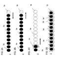
- the display device 2 controls the display of the lighting elements 3, which is described in the following FIGS. 2A to 2C is explained.
- the area of the luminous elements 3 indicates the usable area according to the design of the energy store.
- the number of illuminated display elements 3 decreases with decreasing state of charge (SOC) of the energy store and increases with increasing state of charge of the energy store.
- SOC state of charge
- a fully charged energy storage can be represented by simultaneous illumination of all display elements 3, and a partial load state by lighting only a portion of the display elements, wherein the number of illuminated display elements is proportional to the state of charge of the energy storage.
- an illuminated luminous element is designated by the reference numeral 3b, a non-illuminated.
- the number of illuminated points 3a decreases with increasing consumption of the energy store, which is indicated by the arrow pointing to the left in FIG FIG. 2A is shown. If the vehicle is able to recuperate energy, the number of illuminated points 3a can also increase again during driving, which is indicated by the arrow pointing to the right in FIG FIG. 2B is shown.
- the display device 2 is further configured to signal that an external charge, such as induction, plug-in, etc., is in progress.
- an external charge such as induction, plug-in, etc.
- the last illuminated point 3c flashes slowly, so that the driver immediately recognizes that due to the flashing point 3c there is no fault. Furthermore, the driver recognizes without getting in the vehicle based on the number of illuminated lighting elements 3a as far as the charging process has progressed.
- the display device 2 also has the function to signal malfunctions in the energy storage system. To do this, the entire point bar 3d flashes quickly.
Landscapes
- Engineering & Computer Science (AREA)
- Mechanical Engineering (AREA)
- Transportation (AREA)
- Power Engineering (AREA)
- Chemical & Material Sciences (AREA)
- Combustion & Propulsion (AREA)
- Sustainable Development (AREA)
- Sustainable Energy (AREA)
- Life Sciences & Earth Sciences (AREA)
- Physics & Mathematics (AREA)
- General Physics & Mathematics (AREA)
- Electric Propulsion And Braking For Vehicles (AREA)
- Instrument Panels (AREA)
- Arrangements Of Lighting Devices For Vehicle Interiors, Mounting And Supporting Thereof, Circuits Therefore (AREA)
- Charge And Discharge Circuits For Batteries Or The Like (AREA)
Abstract
Description
- Die Erfindung betrifft ein Fahrzeug, insbesondere einen Omnibus, mit einem Elektroantrieb und einer Anzeigevorrichtung zur Anzeige eines Betriebszustandes, insbesondere eines Ladezustands, eines Energiespeichers des Elektroantriebs.
- Kraftfahrzeuge mit Elektroantrieb, beispielsweise Elektrokraftfahrzeuge oder Hybridelektrokraftfahrzeuge, bei denen ein oder mehrere Räder von einem Elektromotor angetrieben werden, sind aus dem Stand der Technik bekannt. Zunehmend werden auch Omnibusse, beispielsweise Stadtbusse, mit Elektroantrieben ausgestattet. Aus dem Stand der Technik ist ferner bekannt, dass derartige Fahrzeuge eine Anzeigevorrichtung umfassen, die den Betriebszustand, insbesondere den Ladezustand eines Energiespeichers des Elektroantriebs anzeigt. Derartige Anzeigevorrichtungen sind jedoch im Fahrzeugcockpit angeordnet, so dass diese nur für den Fahrer sichtbar ist.
- Einem Kraftfahrzeug ist es in der Regel jedoch nicht unmittelbar anzusehen, ob dieses einen Elektroantrieb aufweist oder nur mit einem konventionellen Antrieb ausgestattet ist. Es wäre jedoch wünschenswert, beispielsweise für umweltbewusste Busfahrgäste, wenn ein Fahrzeug einfach als ein Fahrzeug mit Elektroantrieb identifizierbar wäre.
- Bei Fahrzeugen, die von außen geladen werden kann es vorkommen, dass es beim Ladeprozess zu Störungen kommt, die das Laden des Fahrzeugs verhindern, ohne dass dies von außen bemerkt wird. Gegenmaßnahmen können nicht ergriffen werden. Das Fahrzeug kann zum vorgesehenen Anfahrzeitpunkt nicht genutzt werden.
- Bei Unfallsituationen ist es dem Rettungspersonal nicht sofort ersichtlich, ob das Fahrzeug mit Hochvoltenergiespeichern ausgestattet ist und in welchem Zustand die Energiespeicher sich befinden. Dies ist allerdings für die Sicherheit des Rettungspersonals entscheidend, das sich auf die Situation einstellen können und andere Rettungsmaßnahmen als bei reinen Verbrennungskraftmaschinenfahrzeugen ergreifen können.
- Eine Aufgabe der Erfindung ist es, ein Kraftfahrzeug mit einem Elektroantrieb bereitzustellen, das Nachteile herkömmlicher derartiger Fahrzeuge vermeidet. Eine Aufgabe der Erfindung ist es insbesondere, ein Kraftfahrzeug bereitzustellen, das leicht als Fahrzeug mit Elektroantrieb zu erkennen ist und dessen Betriebszustand der Energiespeicher einfach erkennbar ist.
- Diese Aufgaben werden durch ein Fahrzeug mit den Merkmalen des Hauptanspruchs gelöst. Vorteilhafte Ausführungsformen und Anwendungen der Erfindung sind Gegenstand der abhängigen Ansprüche und werden in der folgenden Beschreibung unter teilweiser Bezugnahme auf die Figuren näher erläutert.
- Das erfindungsgemäße Fahrzeug weist in Übereinstimmung mit dem Stand der Technik einen Elektroantrieb auf. Das Fahrzeug kann ein reines Elektrokraftfahrzeug oder ein Hybridelektrokraftfahrzeug mit und ohne elektrischem Aufladen von außen sein. Gemäß einer hervorgehobenen Anwendung der vorliegenden Erfindung, auf die nachfolgend wiederholt Bezug genommen wird, um die Erfindung zu illustrieren, ist das Fahrzeug ein Omnibus, beispielsweise ein Stadtbus. Es wird jedoch betont, dass die Erfindung nicht auf Busse beschränkt ist, sondern allgemein auf Fahrzeug mit einem Elektroantrieb anwendbar ist.
- Das Fahrzeug umfasst eine Anzeigevorrichtung zur Anzeige eines Betriebszustandes eines Energiespeichers des Elektroantriebs, insbesondere zur Anzeige eines Ladezustands. Der Energiespeicher kann z.B. eine Batterie oder eine Anordnung von Ultrakondensatoren sein.
- Gemäß allgemeinen Gesichtspunkten der Erfindung ist die Anzeigevorrichtung an der Fahrzeugaußenhaut angeordnet, derart, dass die Anzeige des Betriebszustandes von außerhalb des Fahrzeugs sichtbar ist. Der Begriff "Fahrzeugaußenhaut" im Sinne dieser Erfindung umfasst die Fahrzeugkarosserie, die Fahrzeugscheiben, das Fahrzeugdach bzw. Dachaufbauten oder sonstige Elemente und/oder Abschnitte der Fahrzeugwand.
- Das erfindungsgemäße Vorsehen der Anzeigevorrichtung an der Fahrzeugaußenhaut anstatt im Fahrzeugcockpit hat den Vorteil, dass beispielsweise für einen Fahrgast noch vor Betreten des Omnibusses erkennbar ist, ob das Fahrzeug mit einem Elektroantrieb ausgestattet ist. Der außenseitig angezeigte Betriebszustand bietet im Vergleich zu einem einfachen Schriftzug zur Kenntlichmachung als Elektro- oder Hybridfahrzeug weiter den Vorteil, dass auch von außen der Betriebszustand des Energiespeichers, beispielsweise der Ladezustand, erkennbar ist. Dadurch kann beispielsweise ein Fahrer den Fortschritt des Ladevorgangs des Energiespeichers von einem nahegelegenen Ort, z. B. einem Büro oder Café, überprüfen, ohne das Fahrzeug betreten zu müssen.
- Vorzugsweise ist die Anzeigevorrichtung außenseitig am Fahrzeug angeordnet, d. h. an einer Außenfläche des Fahrzeugs. Die Anzeigevorrichtung kann aber auch innenseitig zur der Fahrzeugaußenhaut angeordnet werden, beispielsweise an der Innenseite einer Scheibe, derart, dass die Anzeige des Betriebszustandes von außerhalb des Fahrzeugs sichtbar ist.
- Gemäß einem bevorzugten Ausführungsbeispiel ist die Anzeigevorrichtung an einer Fahrzeugseite angeordnet. Die Anzeigevorrichtung kann aber auch an der Fahrzeugfront oder am Heck angeordnet sein.
- Besonders vorteilhaft ist eine Anordnung der Anzeigevorrichtung in einem oberen Endbereich der Fahrzeugaußenhaut, so dass die Anzeige des Betriebszustandes gut sichtbar ist. Bei einem Omnibus kann die Anzeigevorrichtung gemäß einer besonders vorteilhaften Variante an einem vorderen oberen seitlichen Dachabschnitt des Omnibusses angeordnet sein.
- Ein besonderer Vorzug der Erfindung liegt darin, dass die Anzeigevorrichtung eingerichtet sein kann, anzuzeigen, wenn der Energiespeicher von einer externen Energiequelle aufgeladen wird. Die Erfinder haben festgestellt, dass es beim Anschließen einer externen Stromversorgung zum Aufladen des Energiespeichers des Elektroantriebs oftmals zu Fehlfunktionen kommt, wenn der Ladestecker nicht richtig in die Steckerbuchse eingesteckt wird oder wenn die externe Stromversorgung keinen Strom liefert. Durch das erfindungsgemäße Anzeigen, ob der Energiespeicher extern geladen wird, kann der Fahrer von außerhalb des Fahrzeugs überprüfen, ob ein externer Ladevorgang stattfindet und so ein zeitaufwändiges Wiedereinsteigen in das Fahrzeug und ein Einschalten des Fahrzeugs nach Anbringen des Ladesteckers vermieden werden.
- Eine Möglichkeit der erfindungsgemäßen Realisierung sieht vor, dass die Anzeigevorrichtung eine Vielzahl von Anzeigeelemente umfasst, die linear ausgerichtet angeordnet sind.
- Vorzugsweise nimmt die Anzahl der erleuchteten Anzeigeelemente mit abnehmenden Ladezustand des Energiespeichers ab und mit zunehmenden Ladezustand des Energiespeichers zu. Auf diese Weise kann ein vollständig geladener Energiespeicher durch gleichzeitiges Erleuchten aller Anzeigeelemente dargestellt werden, und ein Teilladezustand durch Erleuchten nur eines Teils der Anzeigeelemente, wobei die Anzahl der erleuchteten Anzeigeelemente proportional zum Ladezustand des Energiespeichers ist.
- Die Anzeigeelemente können als LED Punktmatrizen ausgebildet sein, die ein gut sichtbares, robustes und energieeffizientes Leuchtmittel darstellen. Mittels der LED Punktmatrizen können die einzelnen Anzeigeelemente als farbig erleuchtbare Punktflächen realisiert werden.
- Vorzugsweise ist die Anzeigevorrichtung so dimensioniert, dass die Anzeige des Betriebszustands des Energiespeichers aus mehreren Metern Entfernung zum Fahrzeug, beispielsweise aus mindestens 5 Metern oder mindestens 10 Metern erkennbar ist. Vorzugsweise haben die einzelnen Anzeigeelemente eine Durchmesser von mindestens 10 cm.
- Eine bevorzugte Ausführungsform sieht vor, dass die Anzeigevorrichtung eingerichtet ist, einen Ladezustand des Energiespeichers auch im Nichtfahrbetrieb des Fahrzeugs anzuzeigen. Dies bedeutet, dass der Betriebszustand auch bei einem geparkten, ausgeschalteten Fahrzeug angezeigt wird. Dadurch kann der Ladezustand des Energiespeichers eines geparkten Fahrzeugs von außen überwacht werden.
- Bei einem Omnibus sieht eine weitere erfindungsgemäße Variante vor, dass der Omnibus eine zweite Anzeigevorrichtung zur Anzeige des Betriebszustandes des Energiespeichers des Elektroantriebs umfasst, die im Fahrzeuginneren angeordnet ist, derart, dass der von der zweiten Anzeigevorrichtung angezeigte Betriebszustand für auf Fahrgastsitzen sitzende Fahrgäste sichtbar ist. Der Omnibus umfasst ferner eine dritte, aus dem Stand der Technik bekannte Anzeigevorrichtung zur Anzeige des Betriebszustandes des Energiespeichers des Elektroantriebs, die im Cockpit angeordnet ist.
- Weitere Einzelheiten und Vorteile der Erfindung werden im Folgenden unter Bezug auf die beigefügten Zeichnungen beschrieben. Es zeigen:
- FIG. 1
- eine schematische Seitenansicht eines Fahrzeugs gemäß einem Ausführungsbeispiel; und
- FIG. 2A bis 2D
- verschiedene Anzeigezustände der Anzeigevorrichtung gemäß einem Ausführungsbeispiel.
-
Fig. 1 zeigt eine schematische Seitenansicht eines Omnibusses 1. Der Omnibus 1 verfügt über einen Elektroantrieb und eine Batterie für den Elektroantrieb (nicht gezeigt), die an sich aus dem Stand der Technik bekannt sind und hier nicht weiter beschrieben sind. Die Fahrzeugkarosserie umfasst einen vorderer Dachaufbau 5, der zur Verbesserung der Aerodynamik in Längsrichtung des Omnibusses 1 abflacht. An beiden gegenüberliegenden Seitenflächen 4 des Omnibusses 1 ist außenseitig eine Anzeigevorrichtung 2 befestigt, wovon in Figur 1 nur eine der beiden Anzeigevorrichtungen 2 sichtbar ist. Die Anzeigevorrichtung 2 ist insbesondere an einem seitlichen Abschnitt 6 des Dachaufbaus 5 angeordnet, so dass diese Anzeigevorrichtung 2 gut sichtbar ist und nicht von vorbeifahrenden Fahrzeugen oder von Personen, die sich vor der Seitenfläche 4 des Omnibusses 1 aufhalten, verdeckt werden. Die Anzeigevorrichtung 2 umfasst zwölf linear angeordnete Leuchtelemente 3, die hier als farbig leuchtende Punkt-Matrizen ausgeführt sind. Die Abstrahlrichtung der Punkt-Matrizen ist nach außen, d. h. vom Omnibus 1 weg, so dass das von den Leuchtelementen 3 emittierte Licht von Personen, die sich seitlich vom Bus 1 befinden, gut gesehen werden kann. - Die Anzeigevorrichtung 2 ist mit einer Ladezustandsmesseinheit der Batterie des Elektroantriebs verbunden (nicht gezeigt). Derartige SOC(state of charge)-Messeinheiten und Messverfahren zur SOC-Messung von Batterien sind aus dem Stand der Technik wohl bekannt und daher vorliegend nicht weiter ausgeführt. Abhängig von dem von der SOC-Messeinheit empfangenen Signal steuert die Anzeigevorrichtung 2 die Anzeige der Leuchtelemente 3, was nachfolgend in den
Figuren 2A bis 2C erläutert ist. - Der Bereich der Leuchtelemente 3 gibt den nutzbaren Bereich laut Auslegung des Energiespeichers an. Mit anderen Worten nimmt die Anzahl der erleuchteten Anzeigeelemente 3 mit abnehmenden Ladezustand (SOC) des Energiespeichers ab und mit zunehmenden Ladezustand des Energiespeichers zu. Auf diese Weise kann ein vollständig geladener Energiespeicher durch gleichzeitiges Erleuchten aller Anzeigeelemente 3 dargestellt werden, und ein Teilladezustand durch Erleuchten nur eines Teils der Anzeigeelemente, wobei die Anzahl der erleuchteten Anzeigeelemente proportional zum Ladezustand des Energiespeichers ist.
- Mit den Bezugszeichen 3a ist ein erleuchtetes Leuchtelement bezeichnet, mit dem Bezugszeichen 3b ein nicht-erleuchtetes. Im Fahrbetrieb nimmt mit zunehmendem Verbrauch des Energiespeichers die Anzahl der erleuchteten Punkte 3a ab, was durch den nach links gerichteten Pfeil in
Figur 2A dargestellt ist. Ist das Fahrzeug in der Lage, Energie zu rekuperien, kann auch im Fahrbetrieb die Anzahl der erleuchteten Punkte 3a wieder zunehmen, was durch den nach rechts gerichteten Pfeil inFigur 2B dargestellt ist. - Die Anzeigevorrichtung 2 ist ferner eingerichtet, zu signalisieren, dass ein externer Ladevorgang, beispielsweise durch Induktion, Plug-in etc., im Gange ist. Hierzu blinkt der letzte erleuchtete Punkt 3c langsam, so dass der Fahrer sofort erkennt, dass aufgrund des blinkenden Punktes 3c keine Störung vorliegt. Ferner erkennt der Fahrer, ohne sich im Fahrzeug zu befinden, anhand der Anzahl der erleuchteten Leuchtelemente 3a wie weit der Ladevorgang fortgeschritten ist.
- Die Anzeigevorrichtung 2 hat weiterhin die Funktion Störungen im Energiespeichersystem zu signalisieren. Hierzu blinkt die gesamte Punktleiste 3d schnell.
- Obwohl die Erfindung unter Bezugnahme auf bestimmte Ausführungsbeispiele beschrieben worden ist, ist es für einen Fachmann ersichtlich, das verschiedene Änderungen ausgeführt werden können und Äquivalente als Ersatz verwendet werden können, ohne den Bereich der Erfindung zu verlassen. Zusätzlich können viele Modifikationen ausgeführt werden, um eine Anzeige eines bestimmten Betriebszustand des Energiespeichers oder eine bestimmte konstruktive Ausführung der Anzeigevorrichtung an die Lehre der Erfindung anzupassen, ohne den zugehörigen Bereich zu verlassen. Folglich soll die Erfindung nicht auf das offenbarte bestimmte Ausführungsbeispiel begrenzt sein, sondern die Erfindung soll alle Ausführungsbeispiele umfassen, die in den Bereich der beigefügten Patentansprüche fallen.
-
- 1
- Omnibus
- 2
- Anzeigevorrichtung
- 3
- Leuchtelemente
- 3a
- erleuchtetes Leuchtelement
- 3b
- nicht-erleuchtetes Leuchtelement
- 3c
- blinkendes Leuchtelement
- 3d
- schnell blinkende Leuchtelemente
- 4
- Seitenwand des Omnibus
- 5
- Dachaufbau
- 6
- seitlicher Abschnitt des Dachaufbaus
Claims (12)
- Fahrzeug mit einem Elektroantrieb, insbesondere ein Omnibus (1), mit einer Anzeigevorrichtung (2) zur Anzeige eines Betriebszustandes eines Energiespeichers des Elektroantriebs;
dadurch gekennzeichnet,
dass die Anzeigevorrichtung (2) an einer Fahrzeugaußenhaut angeordnet ist, derart, dass die Anzeige des Betriebszustandes von außerhalb des Fahrzeugs sichtbar ist. - Fahrzeug nach Anspruch 1, dadurch gekennzeichnet, dass die Anzeigevorrichtung (2) außenseitig am Fahrzeug und/oder an einer Fahrzeugseite (4) angeordnet ist.
- Fahrzeug nach Anspruch 1 oder 2, dadurch gekennzeichnet, dass die Anzeigevorrichtung (2) in einem oberen Endbereich der Fahrzeugaußenhaut angeordnet ist.
- Fahrzeug nach einem der vorhergehenden Ansprüche, dadurch gekennzeichnet, dass die Anzeigevorrichtung (2) eingerichtet ist, anzuzeigen, wenn der Energiespeicher von einer externen Energiequelle aufgeladen wird.
- Fahrzeug nach einem der vorhergehenden Ansprüche, dadurch gekennzeichnet, dass das Fahrzeug ein Omnibus (1) ist und dass die Anzeigevorrichtung (2) an einem oberen seitlichen Dachabschnitt (6) des Omnibusses (1) angeordnet ist.
- Fahrzeug nach einem der vorhergehenden Ansprüche, dadurch gekennzeichnet, dass das Fahrzeug ein Omnibus (1) ist und eine zweite Anzeigevorrichtung (2) zur Anzeige des Betriebszustandes des Energiespeichers des Elektroantriebs umfasst, die im Fahrzeuginneren angeordnet ist, derart, dass der von der zweiten Anzeigevorrichtung (2) angezeigte Betriebszustand für auf Fahrgastsitzen sitzende Fahrgäste sichtbar ist.
- Fahrzeug nach einem der vorhergehenden Ansprüche, dadurch gekennzeichnet, dass die Anzeigevorrichtung (2) eine Vielzahl von Anzeigeelemente (3) umfasst, die linear ausgerichtet angeordnet sind.
- Fahrzeug nach Anspruch 7, dadurch gekennzeichnet, dass die Vielzahl von Anzeigeelementen (3) linear angeordnete LED Punktmatrizen oder OLED umfassen.
- Fahrzeug nach Anspruch 7 oder 8, dadurch gekennzeichnet, dass die Anzahl der erleuchteten Anzeigelemente (3) mit abnehmenden Ladezustand des Energiespeichers abnimmt und mit zunehmenden Ladezustand des Energiespeichers zunimmt.
- Fahrzeug nach einem der vorhergehenden Ansprüche, dadurch gekennzeichnet, dass die Anzeigevorrichtung (2) so dimensioniert ist, dass die Anzeige des Betriebszustands des Energiespeichers aus mehreren Metern Entfernung zum Fahrzeug erkennbar ist.
- Fahrzeug nach einem der vorhergehenden Ansprüche, dadurch gekennzeichnet, dass die Anzeigevorrichtung (2) eingerichtet ist, einen Ladungszustand des Energiespeichers auch im Nichtfahrbetrieb des Fahrzeugs anzuzeigen.
- Fahrzeug nach einem der vorhergehenden Ansprüche, dadurch gekennzeichnet, dass die Anzeigevorrichtung (2) eingerichtet ist, eine Fehlfunktion des Energiespeichers im Betrieb und auch im Nichtfahrbetrieb des Fahrzeugs anzuzeigen.
Applications Claiming Priority (1)
| Application Number | Priority Date | Filing Date | Title |
|---|---|---|---|
| DE102013014104.4A DE102013014104A1 (de) | 2013-08-24 | 2013-08-24 | Fahrzeug mit Elektroantrieb und einer Anzeigevorrichtung zur Anzeige eines Betriebszustandes eines Energiespeichers des Elektroantriebs |
Publications (3)
| Publication Number | Publication Date |
|---|---|
| EP2848448A2 true EP2848448A2 (de) | 2015-03-18 |
| EP2848448A3 EP2848448A3 (de) | 2015-08-26 |
| EP2848448B1 EP2848448B1 (de) | 2018-10-03 |
Family
ID=50349417
Family Applications (1)
| Application Number | Title | Priority Date | Filing Date |
|---|---|---|---|
| EP14001059.6A Active EP2848448B1 (de) | 2013-08-24 | 2014-03-21 | Fahrzeug mit Elektroantrieb und einer Anzeigevorrichtung zur Anzeige eines Betriebszustandes eines Energiespeichers des Elektroantriebs |
Country Status (2)
| Country | Link |
|---|---|
| EP (1) | EP2848448B1 (de) |
| DE (1) | DE102013014104A1 (de) |
Cited By (4)
| Publication number | Priority date | Publication date | Assignee | Title |
|---|---|---|---|---|
| CN108407645A (zh) * | 2018-03-23 | 2018-08-17 | 浙江合众新能源汽车有限公司 | 多色充电显示装置 |
| WO2020006570A1 (en) * | 2018-06-29 | 2020-01-02 | Matthew Coburn | Exterior light and charge indicator |
| US11760258B1 (en) * | 2020-05-13 | 2023-09-19 | William S. Lerner | Indicators to identify status and safety of vehicles |
| US12227103B1 (en) | 2020-05-13 | 2025-02-18 | William S. Lerner | Energy supply status indication for a vehicle |
Families Citing this family (2)
| Publication number | Priority date | Publication date | Assignee | Title |
|---|---|---|---|---|
| CN109969029B (zh) * | 2019-04-03 | 2020-12-15 | 广州小鹏汽车科技有限公司 | 一种车辆充电场景下的互动方法及互动系统、车辆 |
| DE102019131997A1 (de) * | 2019-11-26 | 2021-05-27 | Bayerische Motoren Werke Aktiengesellschaft | Verfahren zur Integration eines Displays in eine Karosserieaußenhaut |
Family Cites Families (5)
| Publication number | Priority date | Publication date | Assignee | Title |
|---|---|---|---|---|
| US20100238006A1 (en) * | 2009-03-17 | 2010-09-23 | Ford Global Technologies, Llc | Concealed display for an external surface of a vehicle |
| JP2011182563A (ja) * | 2010-03-02 | 2011-09-15 | Honda Motor Co Ltd | 車両用充電状態表示装置 |
| FR2980646A1 (fr) * | 2011-09-23 | 2013-03-29 | Peugeot Citroen Automobiles Sa | Procede d'affichage de l'etat de charge de la batterie d'un vehicule automobile electrique |
| JP2013086552A (ja) * | 2011-10-13 | 2013-05-13 | Honda Motor Co Ltd | 車両用表示装置 |
| DE102011121058A1 (de) * | 2011-12-14 | 2013-06-20 | Volkswagen Ag | Verfahren und Vorrichtung zur Darstellung einer Information über einen Energiespeicher eines Fahrzeugs |
-
2013
- 2013-08-24 DE DE102013014104.4A patent/DE102013014104A1/de not_active Withdrawn
-
2014
- 2014-03-21 EP EP14001059.6A patent/EP2848448B1/de active Active
Non-Patent Citations (1)
| Title |
|---|
| None |
Cited By (11)
| Publication number | Priority date | Publication date | Assignee | Title |
|---|---|---|---|---|
| CN108407645A (zh) * | 2018-03-23 | 2018-08-17 | 浙江合众新能源汽车有限公司 | 多色充电显示装置 |
| CN108407645B (zh) * | 2018-03-23 | 2020-10-16 | 浙江合众新能源汽车有限公司 | 多色充电显示装置 |
| WO2020006570A1 (en) * | 2018-06-29 | 2020-01-02 | Matthew Coburn | Exterior light and charge indicator |
| CN112424019A (zh) * | 2018-06-29 | 2021-02-26 | 瑞维安知识产权控股有限责任公司 | 外部灯和充电指示器 |
| US11288902B2 (en) | 2018-06-29 | 2022-03-29 | Rivian Ip Holdings, Llc | Exterior light and charge indicator |
| US11718189B2 (en) | 2018-06-29 | 2023-08-08 | Rivian Ip Holdings, Llc | Exterior light and charge indicator |
| CN112424019B (zh) * | 2018-06-29 | 2024-06-04 | 瑞维安知识产权控股有限责任公司 | 外部灯和充电指示器 |
| US12122252B2 (en) | 2018-06-29 | 2024-10-22 | Rivian Ip Holdings, Llc | Exterior light and charge indicator |
| US12552268B2 (en) | 2018-06-29 | 2026-02-17 | Rivian Ip Holdings, Llc | Exterior light and charge indicator |
| US11760258B1 (en) * | 2020-05-13 | 2023-09-19 | William S. Lerner | Indicators to identify status and safety of vehicles |
| US12227103B1 (en) | 2020-05-13 | 2025-02-18 | William S. Lerner | Energy supply status indication for a vehicle |
Also Published As
| Publication number | Publication date |
|---|---|
| EP2848448A3 (de) | 2015-08-26 |
| EP2848448B1 (de) | 2018-10-03 |
| DE102013014104A1 (de) | 2015-02-26 |
Similar Documents
| Publication | Publication Date | Title |
|---|---|---|
| EP2848448B1 (de) | Fahrzeug mit Elektroantrieb und einer Anzeigevorrichtung zur Anzeige eines Betriebszustandes eines Energiespeichers des Elektroantriebs | |
| DE102019126081A1 (de) | Kondensatorzustandsanzeigevorrichtung für Fahrzeuge | |
| DE102018201691B4 (de) | Mobile Notladevorrichtung und Notladeverfahren für eine Batterie eines Kraftfahrzeugs | |
| DE102011121058A1 (de) | Verfahren und Vorrichtung zur Darstellung einer Information über einen Energiespeicher eines Fahrzeugs | |
| DE102008030581A1 (de) | Triebstrang für ein Kraftfahrzeug und Verfahren zum Betreiben eines Triebstrangs eines Kraftfahrzeuges | |
| DE102021123321A1 (de) | Ladekabel mit Ladestecker | |
| DE102010019296A1 (de) | Energieversorgungsvorrichtung mit unterschiedlichen Batterietypen | |
| DE102010014095A1 (de) | Fahrzeugmodul für ein Kraftfahrzeug | |
| DE102014200549A1 (de) | Anzeigevorrichtung für ein Kraftfahrzeug mit elektrischem Fahrantrieb | |
| DE102007042267A1 (de) | Energieflussanzeige für Hybridfahrzeuge | |
| DE202016007685U1 (de) | Kraftfahrzeug mit Warntafel | |
| DE102016221695A1 (de) | Steuereinrichtung für ein Kraftfahrzeug, Kraftfahrzeug und Gespann | |
| DE212006000065U1 (de) | Psychomotorischer Indikator für Verkehrsmittel | |
| DE102016123350B4 (de) | Sattelauflieger, Sattelzug und Verfahren zum Bremsen eines Sattelaufliegers | |
| DE102015106682B4 (de) | Systeme und Verfahren für Ladebuchsenverschluss | |
| DE102019209476A1 (de) | Verfahren zum Aufladen einer Hochvolt-Batterie eines Elektroantriebs eines Fahrzeugs, sowie Energieübertragungssystem für ein Fahrzeug | |
| DE202016008782U1 (de) | Förderwagen mit autonomer Energieversorgung für Notsituationen | |
| DE202019003239U1 (de) | Campingwagen mit Sekundärstromversorgung | |
| DE102021109066B4 (de) | Kupplungsvorrichtung für ein in Zugrichtung hinteres Fahrzeug eines Fahrzeugverbundes | |
| DE102016012174A1 (de) | Antriebs- und/oder Bremsvorrichtung für ein Fahrzeug | |
| DE102016008056A1 (de) | Zum/Beim Aufladen eines elektrischen Energiespeichers eines Fahrzeugs verwendbare Einrichtung mit einer Anzeigeeinrichtung zur Anzeige eines aktuellen Alterungszustands des Energiespeichers | |
| EP3782851A1 (de) | Assistenzsystem für ein schienenfahrzeug | |
| DE102020114320B4 (de) | System zur Energieerzeugung in einer Scheibenbremse | |
| DE102009045003A1 (de) | Automatisierte Parkbremse mit zusätzlichem Pufferspeicher | |
| DE102009002696A1 (de) | Beleuchtungseinrichtung mit Standlicht |
Legal Events
| Date | Code | Title | Description |
|---|---|---|---|
| PUAI | Public reference made under article 153(3) epc to a published international application that has entered the european phase |
Free format text: ORIGINAL CODE: 0009012 |
|
| 17P | Request for examination filed |
Effective date: 20140321 |
|
| AK | Designated contracting states |
Kind code of ref document: A2 Designated state(s): AL AT BE BG CH CY CZ DE DK EE ES FI FR GB GR HR HU IE IS IT LI LT LU LV MC MK MT NL NO PL PT RO RS SE SI SK SM TR |
|
| AX | Request for extension of the european patent |
Extension state: BA ME |
|
| PUAL | Search report despatched |
Free format text: ORIGINAL CODE: 0009013 |
|
| AK | Designated contracting states |
Kind code of ref document: A3 Designated state(s): AL AT BE BG CH CY CZ DE DK EE ES FI FR GB GR HR HU IE IS IT LI LT LU LV MC MK MT NL NO PL PT RO RS SE SI SK SM TR |
|
| AX | Request for extension of the european patent |
Extension state: BA ME |
|
| RIC1 | Information provided on ipc code assigned before grant |
Ipc: B60Q 1/26 20060101ALI20150722BHEP Ipc: H02J 7/00 20060101ALI20150722BHEP Ipc: G01R 31/36 20060101ALI20150722BHEP Ipc: B60L 11/18 20060101ALI20150722BHEP Ipc: B60K 35/00 20060101AFI20150722BHEP |
|
| R17P | Request for examination filed (corrected) |
Effective date: 20151104 |
|
| STAA | Information on the status of an ep patent application or granted ep patent |
Free format text: STATUS: EXAMINATION IS IN PROGRESS |
|
| 17Q | First examination report despatched |
Effective date: 20170526 |
|
| GRAP | Despatch of communication of intention to grant a patent |
Free format text: ORIGINAL CODE: EPIDOSNIGR1 |
|
| RIC1 | Information provided on ipc code assigned before grant |
Ipc: B60L 3/12 20060101ALI20180409BHEP Ipc: B60L 3/00 20060101ALI20180409BHEP Ipc: B60Q 1/00 20060101ALI20180409BHEP Ipc: H02J 7/00 20060101ALI20180409BHEP Ipc: G01R 31/36 20060101ALI20180409BHEP Ipc: B60Q 1/50 20060101ALI20180409BHEP Ipc: B60Q 1/26 20060101ALI20180409BHEP Ipc: B60K 35/00 20060101AFI20180409BHEP Ipc: B60L 11/18 20060101ALI20180409BHEP Ipc: B60L 11/00 20060101ALI20180409BHEP |
|
| STAA | Information on the status of an ep patent application or granted ep patent |
Free format text: STATUS: GRANT OF PATENT IS INTENDED |
|
| INTG | Intention to grant announced |
Effective date: 20180517 |
|
| GRAS | Grant fee paid |
Free format text: ORIGINAL CODE: EPIDOSNIGR3 |
|
| GRAA | (expected) grant |
Free format text: ORIGINAL CODE: 0009210 |
|
| STAA | Information on the status of an ep patent application or granted ep patent |
Free format text: STATUS: THE PATENT HAS BEEN GRANTED |
|
| AK | Designated contracting states |
Kind code of ref document: B1 Designated state(s): AL AT BE BG CH CY CZ DE DK EE ES FI FR GB GR HR HU IE IS IT LI LT LU LV MC MK MT NL NO PL PT RO RS SE SI SK SM TR |
|
| REG | Reference to a national code |
Ref country code: GB Ref legal event code: FG4D Free format text: NOT ENGLISH |
|
| REG | Reference to a national code |
Ref country code: CH Ref legal event code: EP Ref country code: AT Ref legal event code: REF Ref document number: 1048218 Country of ref document: AT Kind code of ref document: T Effective date: 20181015 |
|
| REG | Reference to a national code |
Ref country code: IE Ref legal event code: FG4D Free format text: LANGUAGE OF EP DOCUMENT: GERMAN Ref country code: DE Ref legal event code: R096 Ref document number: 502014009605 Country of ref document: DE |
|
| REG | Reference to a national code |
Ref country code: NL Ref legal event code: FP |
|
| REG | Reference to a national code |
Ref country code: SE Ref legal event code: TRGR |
|
| REG | Reference to a national code |
Ref country code: LT Ref legal event code: MG4D |
|
| PG25 | Lapsed in a contracting state [announced via postgrant information from national office to epo] |
Ref country code: LT Free format text: LAPSE BECAUSE OF FAILURE TO SUBMIT A TRANSLATION OF THE DESCRIPTION OR TO PAY THE FEE WITHIN THE PRESCRIBED TIME-LIMIT Effective date: 20181003 Ref country code: PL Free format text: LAPSE BECAUSE OF FAILURE TO SUBMIT A TRANSLATION OF THE DESCRIPTION OR TO PAY THE FEE WITHIN THE PRESCRIBED TIME-LIMIT Effective date: 20181003 Ref country code: NO Free format text: LAPSE BECAUSE OF FAILURE TO SUBMIT A TRANSLATION OF THE DESCRIPTION OR TO PAY THE FEE WITHIN THE PRESCRIBED TIME-LIMIT Effective date: 20190103 Ref country code: FI Free format text: LAPSE BECAUSE OF FAILURE TO SUBMIT A TRANSLATION OF THE DESCRIPTION OR TO PAY THE FEE WITHIN THE PRESCRIBED TIME-LIMIT Effective date: 20181003 Ref country code: ES Free format text: LAPSE BECAUSE OF FAILURE TO SUBMIT A TRANSLATION OF THE DESCRIPTION OR TO PAY THE FEE WITHIN THE PRESCRIBED TIME-LIMIT Effective date: 20181003 Ref country code: LV Free format text: LAPSE BECAUSE OF FAILURE TO SUBMIT A TRANSLATION OF THE DESCRIPTION OR TO PAY THE FEE WITHIN THE PRESCRIBED TIME-LIMIT Effective date: 20181003 Ref country code: BG Free format text: LAPSE BECAUSE OF FAILURE TO SUBMIT A TRANSLATION OF THE DESCRIPTION OR TO PAY THE FEE WITHIN THE PRESCRIBED TIME-LIMIT Effective date: 20190103 Ref country code: HR Free format text: LAPSE BECAUSE OF FAILURE TO SUBMIT A TRANSLATION OF THE DESCRIPTION OR TO PAY THE FEE WITHIN THE PRESCRIBED TIME-LIMIT Effective date: 20181003 Ref country code: CZ Free format text: LAPSE BECAUSE OF FAILURE TO SUBMIT A TRANSLATION OF THE DESCRIPTION OR TO PAY THE FEE WITHIN THE PRESCRIBED TIME-LIMIT Effective date: 20181003 Ref country code: IS Free format text: LAPSE BECAUSE OF FAILURE TO SUBMIT A TRANSLATION OF THE DESCRIPTION OR TO PAY THE FEE WITHIN THE PRESCRIBED TIME-LIMIT Effective date: 20190203 |
|
| PG25 | Lapsed in a contracting state [announced via postgrant information from national office to epo] |
Ref country code: GR Free format text: LAPSE BECAUSE OF FAILURE TO SUBMIT A TRANSLATION OF THE DESCRIPTION OR TO PAY THE FEE WITHIN THE PRESCRIBED TIME-LIMIT Effective date: 20190104 Ref country code: RS Free format text: LAPSE BECAUSE OF FAILURE TO SUBMIT A TRANSLATION OF THE DESCRIPTION OR TO PAY THE FEE WITHIN THE PRESCRIBED TIME-LIMIT Effective date: 20181003 Ref country code: AL Free format text: LAPSE BECAUSE OF FAILURE TO SUBMIT A TRANSLATION OF THE DESCRIPTION OR TO PAY THE FEE WITHIN THE PRESCRIBED TIME-LIMIT Effective date: 20181003 Ref country code: PT Free format text: LAPSE BECAUSE OF FAILURE TO SUBMIT A TRANSLATION OF THE DESCRIPTION OR TO PAY THE FEE WITHIN THE PRESCRIBED TIME-LIMIT Effective date: 20190203 |
|
| REG | Reference to a national code |
Ref country code: DE Ref legal event code: R097 Ref document number: 502014009605 Country of ref document: DE |
|
| RAP2 | Party data changed (patent owner data changed or rights of a patent transferred) |
Owner name: MAN TRUCK & BUS SE |
|
| PG25 | Lapsed in a contracting state [announced via postgrant information from national office to epo] |
Ref country code: DK Free format text: LAPSE BECAUSE OF FAILURE TO SUBMIT A TRANSLATION OF THE DESCRIPTION OR TO PAY THE FEE WITHIN THE PRESCRIBED TIME-LIMIT Effective date: 20181003 |
|
| PLBE | No opposition filed within time limit |
Free format text: ORIGINAL CODE: 0009261 |
|
| STAA | Information on the status of an ep patent application or granted ep patent |
Free format text: STATUS: NO OPPOSITION FILED WITHIN TIME LIMIT |
|
| PG25 | Lapsed in a contracting state [announced via postgrant information from national office to epo] |
Ref country code: SK Free format text: LAPSE BECAUSE OF FAILURE TO SUBMIT A TRANSLATION OF THE DESCRIPTION OR TO PAY THE FEE WITHIN THE PRESCRIBED TIME-LIMIT Effective date: 20181003 Ref country code: SM Free format text: LAPSE BECAUSE OF FAILURE TO SUBMIT A TRANSLATION OF THE DESCRIPTION OR TO PAY THE FEE WITHIN THE PRESCRIBED TIME-LIMIT Effective date: 20181003 Ref country code: RO Free format text: LAPSE BECAUSE OF FAILURE TO SUBMIT A TRANSLATION OF THE DESCRIPTION OR TO PAY THE FEE WITHIN THE PRESCRIBED TIME-LIMIT Effective date: 20181003 Ref country code: EE Free format text: LAPSE BECAUSE OF FAILURE TO SUBMIT A TRANSLATION OF THE DESCRIPTION OR TO PAY THE FEE WITHIN THE PRESCRIBED TIME-LIMIT Effective date: 20181003 |
|
| 26N | No opposition filed |
Effective date: 20190704 |
|
| REG | Reference to a national code |
Ref country code: DE Ref legal event code: R081 Ref document number: 502014009605 Country of ref document: DE Owner name: MAN TRUCK & BUS SE, DE Free format text: FORMER OWNER: MAN TRUCK & BUS AG, 80995 MUENCHEN, DE |
|
| PG25 | Lapsed in a contracting state [announced via postgrant information from national office to epo] |
Ref country code: MC Free format text: LAPSE BECAUSE OF FAILURE TO SUBMIT A TRANSLATION OF THE DESCRIPTION OR TO PAY THE FEE WITHIN THE PRESCRIBED TIME-LIMIT Effective date: 20181003 Ref country code: SI Free format text: LAPSE BECAUSE OF FAILURE TO SUBMIT A TRANSLATION OF THE DESCRIPTION OR TO PAY THE FEE WITHIN THE PRESCRIBED TIME-LIMIT Effective date: 20181003 |
|
| REG | Reference to a national code |
Ref country code: CH Ref legal event code: PL |
|
| GBPC | Gb: european patent ceased through non-payment of renewal fee |
Effective date: 20190321 |
|
| PG25 | Lapsed in a contracting state [announced via postgrant information from national office to epo] |
Ref country code: LU Free format text: LAPSE BECAUSE OF NON-PAYMENT OF DUE FEES Effective date: 20190321 |
|
| REG | Reference to a national code |
Ref country code: BE Ref legal event code: MM Effective date: 20190331 |
|
| PG25 | Lapsed in a contracting state [announced via postgrant information from national office to epo] |
Ref country code: IE Free format text: LAPSE BECAUSE OF NON-PAYMENT OF DUE FEES Effective date: 20190321 Ref country code: LI Free format text: LAPSE BECAUSE OF NON-PAYMENT OF DUE FEES Effective date: 20190331 Ref country code: CH Free format text: LAPSE BECAUSE OF NON-PAYMENT OF DUE FEES Effective date: 20190331 Ref country code: GB Free format text: LAPSE BECAUSE OF NON-PAYMENT OF DUE FEES Effective date: 20190321 |
|
| PG25 | Lapsed in a contracting state [announced via postgrant information from national office to epo] |
Ref country code: BE Free format text: LAPSE BECAUSE OF NON-PAYMENT OF DUE FEES Effective date: 20190331 |
|
| PG25 | Lapsed in a contracting state [announced via postgrant information from national office to epo] |
Ref country code: TR Free format text: LAPSE BECAUSE OF FAILURE TO SUBMIT A TRANSLATION OF THE DESCRIPTION OR TO PAY THE FEE WITHIN THE PRESCRIBED TIME-LIMIT Effective date: 20181003 |
|
| PG25 | Lapsed in a contracting state [announced via postgrant information from national office to epo] |
Ref country code: MT Free format text: LAPSE BECAUSE OF FAILURE TO SUBMIT A TRANSLATION OF THE DESCRIPTION OR TO PAY THE FEE WITHIN THE PRESCRIBED TIME-LIMIT Effective date: 20181003 |
|
| REG | Reference to a national code |
Ref country code: AT Ref legal event code: MM01 Ref document number: 1048218 Country of ref document: AT Kind code of ref document: T Effective date: 20190321 |
|
| PG25 | Lapsed in a contracting state [announced via postgrant information from national office to epo] |
Ref country code: AT Free format text: LAPSE BECAUSE OF NON-PAYMENT OF DUE FEES Effective date: 20190321 |
|
| PG25 | Lapsed in a contracting state [announced via postgrant information from national office to epo] |
Ref country code: CY Free format text: LAPSE BECAUSE OF FAILURE TO SUBMIT A TRANSLATION OF THE DESCRIPTION OR TO PAY THE FEE WITHIN THE PRESCRIBED TIME-LIMIT Effective date: 20181003 |
|
| PG25 | Lapsed in a contracting state [announced via postgrant information from national office to epo] |
Ref country code: HU Free format text: LAPSE BECAUSE OF FAILURE TO SUBMIT A TRANSLATION OF THE DESCRIPTION OR TO PAY THE FEE WITHIN THE PRESCRIBED TIME-LIMIT; INVALID AB INITIO Effective date: 20140321 |
|
| PG25 | Lapsed in a contracting state [announced via postgrant information from national office to epo] |
Ref country code: MK Free format text: LAPSE BECAUSE OF FAILURE TO SUBMIT A TRANSLATION OF THE DESCRIPTION OR TO PAY THE FEE WITHIN THE PRESCRIBED TIME-LIMIT Effective date: 20181003 |
|
| PGFP | Annual fee paid to national office [announced via postgrant information from national office to epo] |
Ref country code: SE Payment date: 20260323 Year of fee payment: 13 |
|
| PGFP | Annual fee paid to national office [announced via postgrant information from national office to epo] |
Ref country code: DE Payment date: 20260320 Year of fee payment: 13 |
|
| PGFP | Annual fee paid to national office [announced via postgrant information from national office to epo] |
Ref country code: IT Payment date: 20260320 Year of fee payment: 13 |
|
| PGFP | Annual fee paid to national office [announced via postgrant information from national office to epo] |
Ref country code: NL Payment date: 20260323 Year of fee payment: 13 |
|
| PGFP | Annual fee paid to national office [announced via postgrant information from national office to epo] |
Ref country code: FR Payment date: 20260323 Year of fee payment: 13 |