EP2848311A1 - Lame pour un dispositif de découpe - Google Patents
Lame pour un dispositif de découpe Download PDFInfo
- Publication number
- EP2848311A1 EP2848311A1 EP13183838.5A EP13183838A EP2848311A1 EP 2848311 A1 EP2848311 A1 EP 2848311A1 EP 13183838 A EP13183838 A EP 13183838A EP 2848311 A1 EP2848311 A1 EP 2848311A1
- Authority
- EP
- European Patent Office
- Prior art keywords
- knife
- tips
- cutting edges
- holder
- rotor
- Prior art date
- Legal status (The legal status is an assumption and is not a legal conclusion. Google has not performed a legal analysis and makes no representation as to the accuracy of the status listed.)
- Withdrawn
Links
Images


Classifications
-
- B—PERFORMING OPERATIONS; TRANSPORTING
- B02—CRUSHING, PULVERISING, OR DISINTEGRATING; PREPARATORY TREATMENT OF GRAIN FOR MILLING
- B02C—CRUSHING, PULVERISING, OR DISINTEGRATING IN GENERAL; MILLING GRAIN
- B02C18/00—Disintegrating by knives or other cutting or tearing members which chop material into fragments
- B02C18/06—Disintegrating by knives or other cutting or tearing members which chop material into fragments with rotating knives
- B02C18/14—Disintegrating by knives or other cutting or tearing members which chop material into fragments with rotating knives within horizontal containers
- B02C18/145—Disintegrating by knives or other cutting or tearing members which chop material into fragments with rotating knives within horizontal containers with knives spaced axially and circumferentially on the periphery of a cylindrical rotor unit
-
- B—PERFORMING OPERATIONS; TRANSPORTING
- B02—CRUSHING, PULVERISING, OR DISINTEGRATING; PREPARATORY TREATMENT OF GRAIN FOR MILLING
- B02C—CRUSHING, PULVERISING, OR DISINTEGRATING IN GENERAL; MILLING GRAIN
- B02C18/00—Disintegrating by knives or other cutting or tearing members which chop material into fragments
- B02C18/06—Disintegrating by knives or other cutting or tearing members which chop material into fragments with rotating knives
- B02C18/16—Details
- B02C18/18—Knives; Mountings thereof
Definitions
- the present invention relates to a knife for a comminution device for comminuting, for example, commercial waste, industrial waste and / or household waste and a knife holder for attaching such a knife to the rotor of a comminution device.
- Industrial waste, industrial waste, household waste, etc. for example (hard) plastic, textiles, composites, rubber or waste wood (such as pallets and chipboard), require comminution before being finally disposed of or, in particular, before being returned to the recycling cycle.
- single or multi-shaft shredders are known in the prior art, which are fed, for example, by wheel loaders, forklifts or conveyor belts via a hopper for material feed.
- a central element of a conventional comminuting device is a rotor unit comprising a rotor equipped with knives.
- the knives are fastened, for example by screwing on knife carriers, which may be welded or screwed into knife pockets, the knife pockets are milled in the rotor shell.
- the comminution of the discontinued material is generally between the blades rotating with the rotor and stationary ones, i. non-rotating counter knives (stator knives, scraper combs).
- FIG. 1 illustrates a knife of the prior art.
- the knife has four tips 1, 2, 3 and 4, in which respective cutting edges 5 converge.
- the cutting edges are concave in the example of the prior art shown.
- the knife is adapted to be attached to a support surface 6 on a knife holder.
- a central hole 7 is provided for inserting a fastener for interchangeably attaching the knife to a knife holder.
- Such a knife is fixed with one of the tips 1, 2, 3 or 4 ahead on the circumference of a rotor to a corresponding blade holder. Since the knives are often made of hardened steel or eg hard metal, it is important that there is an optimal contact between the knife holder and the knife. If this is not the case, knife breaks may occur.
- a knife for a comminution device wherein the knife has exactly two base surfaces and at least three side surfaces and a plurality of tips (the plurality being equal to the number of side surfaces).
- a pair of two cutting edges converge and there is at least one of the pairs of cutting edges and thus one of the plurality of tips on one of the two bases and another of the pairs of cutting edges and thus another of the plurality of tips on the other the two bases of the knife.
- the cutting edges are at least parts of the edges of the respective side surfaces.
- the comminution device may be a waste comminution device for comminuting industrial waste and / or agricultural waste.
- the waste crusher may be designed to shred wood waste, textiles, carpets, rubber tires, etc.
- the knife may be made of hardened steel, such as hardened tool steel. It is understood that the tips can also be provided in a rounded shape.
- a number of tips are provided on one of the two bases. If one of these tips becomes worn after use in a comminution device, another tip of the same base can be used by a corresponding rotation of the blade about an axis which extends perpendicularly through the two base surfaces. Cutting edges, which converge in points on the other base of the knife, are not affected, since they do not interfere with the comminution process. If all the tips / cutting edges of the one base of the knife gradually worn, the knife can be rotated about an axis that passes through two of the side surfaces by 180 °, and so tips and cutting edges of the other of the two bases can be used.
- the knife may have exactly four tips, and in this case two of the four tips and the respective pairs of cutting edges converging in the tips are formed on one of the two bases and the two others of the tips and the respective pairs converging in the two other tips formed by cutting edges on the other of the two base surfaces.
- This allows a 4-fold usability of the knife. This is ensured, in particular, when the two tips on one of the two base surfaces face each other and the other two tips on the other of the two base surfaces are opposite each other.
- the knife may be substantially in the form of a parallelepiped (consisting of two base surfaces and four side surfaces), in particular a cuboid.
- the two base surfaces may form essentially parallel, substantially square surfaces.
- a first tip may be used on one of the bases of a cuboid blade until it is worn. Thereafter, in this example, the knife is rotated through 180 ° about an axis perpendicular to the two bases, and the tip opposite the first tip on the same base of the knife is used until worn. Subsequently, in this example, the knife is rotated by 180 ° about an axis which extends perpendicularly through two side surfaces of the cuboid knife.
- the two peaks formed diagonally opposite one another on the other of the two base surfaces and the cutting edges converging in these tips can be successively used. Overall, this ensures that actually all four tips are used within the framework of a 4-fold usability of the knife.
- the knife according to the invention is a concave knife, ie the cutting edges have, in a side view of the knife, a concave profile on one of the edges of the respective side face at least in one area.
- one or more pairs of cutting edges may be concave.
- the bases are not consistently flat, but have a concave profile at least in a side view.
- the knife of each of the examples described above may be formed for attachment to a knife holder attached to a rotor of a shredding device.
- the knife may have one or more bores or one or more threads for receiving a fastening means for attachment to the knife holder.
- the fastening means may in particular comprise a screw or a bolt or a clamping pin.
- the knife may be configured to be attached directly to the rotor.
- the knife in a concave embodiment has a support surface in the region of one of the base surfaces on which the knife, in particular using a shim, can be fastened to the knife holder, and at least one of the tips protrudes over the support surface (in the direction perpendicular to Footprint or footprint) (see detailed description below).
- a tip can protrude perpendicular to the base surface over the support surface, the concave portion relative to a case in which the tip does not protrude beyond the support surface, increased at the same curvature and thus the "aggressiveness" of the knife can be increased.
- a knife-related knife-cooperating blade holder adapted for attachment to a rotor of a comminution device and for attachment of a knife according to any of the previously described examples.
- Such a knife holder may have a central area in which the knife is attached to it, which is raised relative to the peripheral areas for attachment of a knife with tips that protrude beyond the support surface.
- the central portion of the knife holder can contact a central portion of a concave knife, even if the tips of the concave knife protrude perpendicular to its base surfaces over the base surfaces.
- a comminution device is provided with a rotor comprising a rotor shell, wherein the rotor shell has said knife holder attached thereto and / or therein and the knife holder has a knife attached thereto according to one of the previously described examples.
- a method of attaching a knife according to any one of the above-described examples to a knife holder according to any of the above-described Examples providing the steps of providing a shim and attaching the blade to the blade holder using the shim.
- knives of different "aggressiveness" see below can be attached to the knife holder (with the shim between the knife holder and the knife).
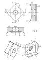
- FIG. 2 An example of a knife according to the invention for a comminution device is shown in FIG. 2 shown.
- the concave knife shown has four tips 11, 12, 13 and 14.
- the knife has essentially the shape of a cuboid with two bases G and G '(one of which is in plan view on the left side of FIG. 2 shown) and four side surfaces S.
- tips 11, 12, 13 and 14 are formed on the same base of the blade.
- the opposing tips 11 and 12 are formed on one of the two base surfaces G of the cuboid blade and the opposing tips 13 and 14 on the other of the two base surfaces G 'of the cuboid blade.
- the tips 11, 12, 13 and 14 converge respective concave cutting edges 15 (see in particular the second illustration from the left of FIG. 2 ).
- Each tip is formed by two converging cutting edges 15 and an edge converging in it with the cutting edges, which is formed by two side surfaces S.
- each base On each base an area is formed as a support surface 16 to which the knife can be attached to a knife holder.
- the tips (in the direction of an axis perpendicular through the base surfaces and parallel to the side surfaces) do not project beyond the level of the bearing surfaces 16.
- the knife comprises a bore 17 through which a fastener, such as a screw, can be inserted to attach the knife to a knife holder.
- the tip 11 may first be used until it is worn, and after it has been worn by rotation of the knife in the knife holder through 180 ° about an axis perpendicular through the two bases G, G ', the tip 12.
- the knife After wear thereof the knife can be rotated by 90 ° about an axis extending perpendicularly through the two base surfaces G, G 'and rotated 180 ° about an axis that extends perpendicularly through two side surfaces S, around the tip 13 or 14 to use.
- the rotation of the knife tips by 90 °, front to back ensures that even after use, for example, the front, for the use of the back still an optimal support surface is guaranteed. The reason for this is the decreasing wear from the tip to the middle (area of blade engagement).
- a shim 28 may be provided as shown in FIG. 3 is shown.
- the knife shown is similar or identical to the knife used in FIG. 2 is shown, and includes four tips 21, 22, 23 and 24, cutting edges 25 and a bore 27.
- the attachment can be made via a shim 28, so that the tips 21, 22, 23 and 24 in the direction perpendicular to the base surfaces over the respective bearing surfaces and can protrude perpendicular to these.
- a positive connection of the knife with a conventional knife holder can be done via the shim 28.
- a knife holder may be suitably adapted to receive a knife in which the tips 21, 22, 23 and 24 project beyond the respective bearing surfaces perpendicular to the base surfaces (of the respective bearing surface).
- a knife holder has a receiving portion with a central portion and a peripheral portion, the central portion, in which the knife is attached to it in contact therewith, being raised toward the male knife opposite to the peripheral portion.
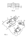
- FIG. 4 illustrates the measure A for the "aggressiveness".
- the shim 28 provides the advantage that blades of varying aggressiveness can be attached to the rotor or knife holder, respectively. Also, when using the shim 28, conventional cuboid blades can be used in exchange with the knives according to the invention.
- FIG. 5 shows a rotor shell M of a rotor of a crushing device.
- the knife holders 100 may be welded or releasably threaded in the pockets.
- knives 200 are fastened by means of screws.
- the knives may be the above-described knives and the knife holders 100 may be formed for mounting the knives described above. If the knife holder 100 for mounting knives with increased "aggressiveness" formed, ie for attachment of knives with tips that protrude perpendicular to the base surfaces of the knife over the respective bearing surfaces, so they can in the central area around the hole through which the Screws 150 are guided, an increase in peripheral areas have to ensure a positive reliable attachment of the knife.
Landscapes
- Engineering & Computer Science (AREA)
- Food Science & Technology (AREA)
- Crushing And Pulverization Processes (AREA)
Priority Applications (1)
| Application Number | Priority Date | Filing Date | Title |
|---|---|---|---|
| EP13183838.5A EP2848311A1 (fr) | 2013-09-11 | 2013-09-11 | Lame pour un dispositif de découpe |
Applications Claiming Priority (1)
| Application Number | Priority Date | Filing Date | Title |
|---|---|---|---|
| EP13183838.5A EP2848311A1 (fr) | 2013-09-11 | 2013-09-11 | Lame pour un dispositif de découpe |
Publications (1)
| Publication Number | Publication Date |
|---|---|
| EP2848311A1 true EP2848311A1 (fr) | 2015-03-18 |
Family
ID=49223549
Family Applications (1)
| Application Number | Title | Priority Date | Filing Date |
|---|---|---|---|
| EP13183838.5A Withdrawn EP2848311A1 (fr) | 2013-09-11 | 2013-09-11 | Lame pour un dispositif de découpe |
Country Status (1)
| Country | Link |
|---|---|
| EP (1) | EP2848311A1 (fr) |
Cited By (4)
| Publication number | Priority date | Publication date | Assignee | Title |
|---|---|---|---|---|
| CN104888912A (zh) * | 2015-06-04 | 2015-09-09 | 福建省大德投资发展有限公司 | 植物纤维切碎机及其切碎方法和应用 |
| CN106216027A (zh) * | 2016-08-30 | 2016-12-14 | 浙江华莎驰机械有限公司 | 一种碎枝机齿头结构 |
| EP3248688A1 (fr) | 2016-05-27 | 2017-11-29 | UNTHA shredding technology GmbH | Couteau de broyeur |
| EP3892378A1 (fr) * | 2020-04-09 | 2021-10-13 | Manuel Lindner | Couteau pour un dispositif de broyage |
Citations (3)
| Publication number | Priority date | Publication date | Assignee | Title |
|---|---|---|---|---|
| DE9320443U1 (de) * | 1992-01-15 | 1994-08-11 | Gross, Stefan, 74074 Heilbronn | Zerkleinerungsvorrichtung und Messerelement für eine Zerkleinerungsvorrichtung |
| DE202008007222U1 (de) * | 2008-05-29 | 2008-07-31 | Grindermax Gmbh | Hohlmesser |
| EP2599553A2 (fr) * | 2011-11-29 | 2013-06-05 | Pallmann Maschinenfabrik GmbH & Co. KG | Unité d'outil et outil de coupe ou d'estampillage pour un dispositif de broyage, et dispositif équipé de celui-ci |
-
2013
- 2013-09-11 EP EP13183838.5A patent/EP2848311A1/fr not_active Withdrawn
Patent Citations (3)
| Publication number | Priority date | Publication date | Assignee | Title |
|---|---|---|---|---|
| DE9320443U1 (de) * | 1992-01-15 | 1994-08-11 | Gross, Stefan, 74074 Heilbronn | Zerkleinerungsvorrichtung und Messerelement für eine Zerkleinerungsvorrichtung |
| DE202008007222U1 (de) * | 2008-05-29 | 2008-07-31 | Grindermax Gmbh | Hohlmesser |
| EP2599553A2 (fr) * | 2011-11-29 | 2013-06-05 | Pallmann Maschinenfabrik GmbH & Co. KG | Unité d'outil et outil de coupe ou d'estampillage pour un dispositif de broyage, et dispositif équipé de celui-ci |
Cited By (6)
| Publication number | Priority date | Publication date | Assignee | Title |
|---|---|---|---|---|
| CN104888912A (zh) * | 2015-06-04 | 2015-09-09 | 福建省大德投资发展有限公司 | 植物纤维切碎机及其切碎方法和应用 |
| EP3248688A1 (fr) | 2016-05-27 | 2017-11-29 | UNTHA shredding technology GmbH | Couteau de broyeur |
| WO2017201557A1 (fr) | 2016-05-27 | 2017-11-30 | Untha Shredding Technology Gmbh | Couteau pour broyeur |
| CN106216027A (zh) * | 2016-08-30 | 2016-12-14 | 浙江华莎驰机械有限公司 | 一种碎枝机齿头结构 |
| EP3892378A1 (fr) * | 2020-04-09 | 2021-10-13 | Manuel Lindner | Couteau pour un dispositif de broyage |
| WO2021204954A1 (fr) * | 2020-04-09 | 2021-10-14 | Manuel Lindner | Lame pour un dispositif de concassage |
Similar Documents
| Publication | Publication Date | Title |
|---|---|---|
| EP2679309B1 (fr) | Dispositif de broyage comprenant un rotor de broyage avec lame traversante | |
| EP2191901B1 (fr) | Broyeuse et son procédé de fonctionnement | |
| DE102009060523A1 (de) | Zerkleinerungsvorrichtung mit Gegenmessereinrichtung | |
| EP2848311A1 (fr) | Lame pour un dispositif de découpe | |
| EP2620218A1 (fr) | Anneau broyeur d'un cylindre broyeur | |
| WO2017201557A1 (fr) | Couteau pour broyeur | |
| EP2698207B1 (fr) | Système de coupe à deux arbres à plusieurs niveaux | |
| EP2374544B1 (fr) | Dispositif de broyage de matériaux compostables | |
| EP2537588B1 (fr) | Déchiqueteur avec lames à plusieurs tranchants | |
| EP3315201A1 (fr) | Broyeur pour une machine à broyer | |
| DE112011104021T5 (de) | Tischeinheit für eine Materialzerkleinerungsmaschine | |
| EP3195934A1 (fr) | Dispositif de broyage et procédé de fonctionnement d'un tel dispositif de broyage | |
| EP3290120B1 (fr) | Rotor de broyeur doté d'un porte-lames fixé de manière amovible | |
| DE202010005584U1 (de) | Zerkleinerungsmaschine | |
| DE112015004361T5 (de) | Perforierter Rotationsschneider | |
| DE102011100067B4 (de) | Fischschupper | |
| DE602004008495T2 (de) | Industrieller Schredder | |
| EP3223951A1 (fr) | Bague coupante de stator, système de coupe comprenant ladite bague et broyeuse | |
| EP3892378A1 (fr) | Couteau pour un dispositif de broyage | |
| DE60319313T2 (de) | Apparat zum Zerhacken | |
| DE20310251U1 (de) | Zerkleinerungsvorrichtung | |
| DE19537581C2 (de) | Messeranordnung für eine Zerkleinerungsvorrichtung, zugehöriges Messer und Verfahren zu dessen Herstellung | |
| DE102012005913A1 (de) | Messerhalteeinrichtung | |
| DE202017000378U1 (de) | Messertrommel zum Zerkleinern von Holz | |
| DE102010014799A1 (de) | Schneidplatte für eine Vorrichtung zum Zerkleinern von kompostierbarem Material |
Legal Events
| Date | Code | Title | Description |
|---|---|---|---|
| PUAI | Public reference made under article 153(3) epc to a published international application that has entered the european phase |
Free format text: ORIGINAL CODE: 0009012 |
|
| 17P | Request for examination filed |
Effective date: 20140425 |
|
| AK | Designated contracting states |
Kind code of ref document: A1 Designated state(s): AL AT BE BG CH CY CZ DE DK EE ES FI FR GB GR HR HU IE IS IT LI LT LU LV MC MK MT NL NO PL PT RO RS SE SI SK SM TR |
|
| AX | Request for extension of the european patent |
Extension state: BA ME |
|
| GRAP | Despatch of communication of intention to grant a patent |
Free format text: ORIGINAL CODE: EPIDOSNIGR1 |
|
| INTG | Intention to grant announced |
Effective date: 20160107 |
|
| STAA | Information on the status of an ep patent application or granted ep patent |
Free format text: STATUS: THE APPLICATION IS DEEMED TO BE WITHDRAWN |
|
| 18D | Application deemed to be withdrawn |
Effective date: 20160510 |