EP2845732B1 - Sheet-fed printing press and process for orienting magnetic flakes contained in an ink or varnish vehicle applied on a sheet-like substrate - Google Patents
Sheet-fed printing press and process for orienting magnetic flakes contained in an ink or varnish vehicle applied on a sheet-like substrate Download PDFInfo
- Publication number
- EP2845732B1 EP2845732B1 EP14193754.0A EP14193754A EP2845732B1 EP 2845732 B1 EP2845732 B1 EP 2845732B1 EP 14193754 A EP14193754 A EP 14193754A EP 2845732 B1 EP2845732 B1 EP 2845732B1
- Authority
- EP
- European Patent Office
- Prior art keywords
- substrate
- magnetic
- cylinder body
- ink
- field
- Prior art date
- Legal status (The legal status is an assumption and is not a legal conclusion. Google has not performed a legal analysis and makes no representation as to the accuracy of the status listed.)
- Active
Links
- 239000000758 substrate Substances 0.000 title claims description 64
- 239000002966 varnish Substances 0.000 title claims description 49
- 238000007639 printing Methods 0.000 title claims description 47
- 238000000034 method Methods 0.000 title claims description 24
- 230000008569 process Effects 0.000 title claims description 22
- 238000012545 processing Methods 0.000 claims description 47
- 230000001939 inductive effect Effects 0.000 claims description 44
- 238000001723 curing Methods 0.000 claims description 30
- 238000001035 drying Methods 0.000 claims description 28
- 238000007650 screen-printing Methods 0.000 claims description 18
- 230000005855 radiation Effects 0.000 claims description 7
- 238000012546 transfer Methods 0.000 claims description 5
- 238000003848 UV Light-Curing Methods 0.000 claims description 4
- 239000000976 ink Substances 0.000 description 39
- 230000002093 peripheral effect Effects 0.000 description 8
- 238000000926 separation method Methods 0.000 description 5
- 230000000694 effects Effects 0.000 description 4
- 238000004519 manufacturing process Methods 0.000 description 3
- 230000008901 benefit Effects 0.000 description 2
- 238000006073 displacement reaction Methods 0.000 description 2
- 230000001747 exhibiting effect Effects 0.000 description 2
- 239000000463 material Substances 0.000 description 2
- 239000011159 matrix material Substances 0.000 description 2
- 238000012986 modification Methods 0.000 description 2
- 230000004048 modification Effects 0.000 description 2
- 230000035699 permeability Effects 0.000 description 2
- 238000011144 upstream manufacturing Methods 0.000 description 2
- XAGFODPZIPBFFR-UHFFFAOYSA-N aluminium Chemical compound [Al] XAGFODPZIPBFFR-UHFFFAOYSA-N 0.000 description 1
- 229910052782 aluminium Inorganic materials 0.000 description 1
- 239000004411 aluminium Substances 0.000 description 1
- 230000001419 dependent effect Effects 0.000 description 1
- 238000007603 infrared drying Methods 0.000 description 1
- 238000003780 insertion Methods 0.000 description 1
- 230000037431 insertion Effects 0.000 description 1
- 239000000696 magnetic material Substances 0.000 description 1
- 230000003287 optical effect Effects 0.000 description 1
- 239000000049 pigment Substances 0.000 description 1
- 238000007493 shaping process Methods 0.000 description 1
- 238000012360 testing method Methods 0.000 description 1
Images


Classifications
-
- B—PERFORMING OPERATIONS; TRANSPORTING
- B41—PRINTING; LINING MACHINES; TYPEWRITERS; STAMPS
- B41F—PRINTING MACHINES OR PRESSES
- B41F19/00—Apparatus or machines for carrying out printing operations combined with other operations
-
- B—PERFORMING OPERATIONS; TRANSPORTING
- B05—SPRAYING OR ATOMISING IN GENERAL; APPLYING FLUENT MATERIALS TO SURFACES, IN GENERAL
- B05D—PROCESSES FOR APPLYING FLUENT MATERIALS TO SURFACES, IN GENERAL
- B05D3/00—Pretreatment of surfaces to which liquids or other fluent materials are to be applied; After-treatment of applied coatings, e.g. intermediate treating of an applied coating preparatory to subsequent applications of liquids or other fluent materials
- B05D3/06—Pretreatment of surfaces to which liquids or other fluent materials are to be applied; After-treatment of applied coatings, e.g. intermediate treating of an applied coating preparatory to subsequent applications of liquids or other fluent materials by exposure to radiation
- B05D3/061—Pretreatment of surfaces to which liquids or other fluent materials are to be applied; After-treatment of applied coatings, e.g. intermediate treating of an applied coating preparatory to subsequent applications of liquids or other fluent materials by exposure to radiation using U.V.
- B05D3/065—After-treatment
- B05D3/067—Curing or cross-linking the coating
-
- B—PERFORMING OPERATIONS; TRANSPORTING
- B05—SPRAYING OR ATOMISING IN GENERAL; APPLYING FLUENT MATERIALS TO SURFACES, IN GENERAL
- B05D—PROCESSES FOR APPLYING FLUENT MATERIALS TO SURFACES, IN GENERAL
- B05D3/00—Pretreatment of surfaces to which liquids or other fluent materials are to be applied; After-treatment of applied coatings, e.g. intermediate treating of an applied coating preparatory to subsequent applications of liquids or other fluent materials
- B05D3/20—Pretreatment of surfaces to which liquids or other fluent materials are to be applied; After-treatment of applied coatings, e.g. intermediate treating of an applied coating preparatory to subsequent applications of liquids or other fluent materials by magnetic fields
- B05D3/203—Pretreatment of surfaces to which liquids or other fluent materials are to be applied; After-treatment of applied coatings, e.g. intermediate treating of an applied coating preparatory to subsequent applications of liquids or other fluent materials by magnetic fields pre-treatment by magnetic fields
-
- B—PERFORMING OPERATIONS; TRANSPORTING
- B41—PRINTING; LINING MACHINES; TYPEWRITERS; STAMPS
- B41F—PRINTING MACHINES OR PRESSES
- B41F15/00—Screen printers
- B41F15/08—Machines
- B41F15/0804—Machines for printing sheets
- B41F15/0809—Machines for printing sheets with cylindrical or belt-like screens
-
- B—PERFORMING OPERATIONS; TRANSPORTING
- B41—PRINTING; LINING MACHINES; TYPEWRITERS; STAMPS
- B41F—PRINTING MACHINES OR PRESSES
- B41F15/00—Screen printers
- B41F15/08—Machines
- B41F15/12—Machines with auxiliary equipment, e.g. for drying printed articles
-
- B—PERFORMING OPERATIONS; TRANSPORTING
- B41—PRINTING; LINING MACHINES; TYPEWRITERS; STAMPS
- B41F—PRINTING MACHINES OR PRESSES
- B41F19/00—Apparatus or machines for carrying out printing operations combined with other operations
- B41F19/002—Apparatus or machines for carrying out printing operations combined with other operations with means for applying specific material other than ink
- B41F19/005—Apparatus or machines for carrying out printing operations combined with other operations with means for applying specific material other than ink with means for applying metallic, conductive or chargeable material
-
- B—PERFORMING OPERATIONS; TRANSPORTING
- B41—PRINTING; LINING MACHINES; TYPEWRITERS; STAMPS
- B41F—PRINTING MACHINES OR PRESSES
- B41F21/00—Devices for conveying sheets through printing apparatus or machines
- B41F21/08—Combinations of endless conveyors and grippers
-
- B—PERFORMING OPERATIONS; TRANSPORTING
- B41—PRINTING; LINING MACHINES; TYPEWRITERS; STAMPS
- B41F—PRINTING MACHINES OR PRESSES
- B41F23/00—Devices for treating the surfaces of sheets, webs, or other articles in connection with printing
- B41F23/04—Devices for treating the surfaces of sheets, webs, or other articles in connection with printing by heat drying, by cooling, by applying powders
- B41F23/044—Drying sheets, e.g. between two printing stations
- B41F23/045—Drying sheets, e.g. between two printing stations by radiation
- B41F23/0453—Drying sheets, e.g. between two printing stations by radiation by ultraviolet dryers
-
- B—PERFORMING OPERATIONS; TRANSPORTING
- B05—SPRAYING OR ATOMISING IN GENERAL; APPLYING FLUENT MATERIALS TO SURFACES, IN GENERAL
- B05D—PROCESSES FOR APPLYING FLUENT MATERIALS TO SURFACES, IN GENERAL
- B05D2252/00—Sheets
- B05D2252/02—Sheets of indefinite length
-
- B—PERFORMING OPERATIONS; TRANSPORTING
- B41—PRINTING; LINING MACHINES; TYPEWRITERS; STAMPS
- B41M—PRINTING, DUPLICATING, MARKING, OR COPYING PROCESSES; COLOUR PRINTING
- B41M3/00—Printing processes to produce particular kinds of printed work, e.g. patterns
- B41M3/14—Security printing
-
- B—PERFORMING OPERATIONS; TRANSPORTING
- B41—PRINTING; LINING MACHINES; TYPEWRITERS; STAMPS
- B41M—PRINTING, DUPLICATING, MARKING, OR COPYING PROCESSES; COLOUR PRINTING
- B41M7/00—After-treatment of prints, e.g. heating, irradiating, setting of the ink, protection of the printed stock
- B41M7/0045—After-treatment of prints, e.g. heating, irradiating, setting of the ink, protection of the printed stock using protective coatings or film forming compositions cured by mechanical wave energy, e.g. ultrasonics, cured by electromagnetic radiation or waves, e.g. ultraviolet radiation, electron beams, or cured by magnetic or electric fields, e.g. electric discharge, plasma
-
- B—PERFORMING OPERATIONS; TRANSPORTING
- B41—PRINTING; LINING MACHINES; TYPEWRITERS; STAMPS
- B41M—PRINTING, DUPLICATING, MARKING, OR COPYING PROCESSES; COLOUR PRINTING
- B41M7/00—After-treatment of prints, e.g. heating, irradiating, setting of the ink, protection of the printed stock
- B41M7/0081—After-treatment of prints, e.g. heating, irradiating, setting of the ink, protection of the printed stock using electromagnetic radiation or waves, e.g. ultraviolet radiation, electron beams
Definitions
- the present invention generally relates to a sheet-fed printing press and process for orienting magnetic flakes contained in an ink or varnish vehicle applied on a sheet-like substrate.
- the present invention is especially applicable and usable in the context of the production of security documents, such as banknotes.
- a printing press comprising a cylinder body for orienting magnetic flakes is known as such in the art.
- Such a printing press is for instance disclosed in International application No. WO 2005/000585 A1 filed in the name of the present Applicant.
- FIG. 1 One embodiment of a sheet-fed printing press disclosed in International application No. WO 2005/000585 A1 is represented in Figure 1 .
- This printing press is adapted to print sheets according to the silk-screen printing process and comprises a feeding station 1 for feeding successive sheets to a silk-screen printing group 2 where silk-screen patterns are applied onto the sheets.
- the printing group 2 comprises an impression cylinder 2a cooperating with two screen cylinders 2b, 2c placed in succession along the printing path of the sheets.
- the freshly printed sheets are transported by means of a conveyor system 3 to a delivery station 4 comprising a plurality of delivery pile units, three in this example.
- the conveyor system 3 is typically an endless chain conveyor system comprising a plurality of spaced-apart gripper bars (not shown in Figure 1 ) extending transversely to the sheet transporting direction, each gripper bar comprising grippers for holding a leading edge of the sheets.
- a processing unit 10* comprising a cylinder 10 carrying a plurality of magnetic-field-inducing devices is located along the path of the sheets carried by the chain conveyor system 3.
- This cylinder 10 is designed to apply a magnetic field to selected locations of the sheets for the purpose of orienting magnetic flakes contained in the patterns of ink or varnish which have been freshly-applied on the sheets in the printing group 2.
- a drying or curing unit 5 is provided downstream of the cylinder 10 for drying, respectively curing, the ink/varnish applied onto the sheets after the magnetic flakes have been oriented, such unit 5 being typically an infrared drying unit or a UV curing unit depending on the type of ink or varnish used.
- Silk-screen printing is in particular adopted, in the context of the production of security documents, such as banknotes, to print optically-variable patterns onto the documents, including so-called iridescent patterns and OVI® patterns (OVI® is a registered trademark of SICPA Holding SA, Switzerland).
- OVI® is a registered trademark of SICPA Holding SA, Switzerland.
- Such patterns are printed using inks or varnishes containing special pigments or flakes producing optically variable effects.
- Magnetic flakes are also known in the art, which flakes have the particularity that they can be oriented or aligned by an appropriately-applied magnetic field. While the terminology “magnetic flakes” is used, it should be understood that this terminology designates flakes that can be oriented using a magnetic field, including flakes that are not necessarily magnetic per se but are capable of being oriented using a magnetic field. Such magnetic flakes and method for orienting such magnetic flakes are discussed in particular in US Patent No. US 4,838,648 , European patent application No. EP 0 686 675 A1 , and International applications Nos. WO 02/073250 A2 , WO 03/000801 A2 , WO 2004/007095 A2 , WO 2004/007096 A2 , WO 2005/002866 A1 .
- the most convenient method to apply the above magnetic flakes is by silk-screen printing as discussed in the above-mentioned International application WO 2005/000585 A1 .
- This is mainly due to the fact that the flakes have a relatively important size which restricts the choice of available printing processes for applying inks or varnishes containing such flakes.
- silk-screen printing constitutes the most convenient printing process to achieve this goal.
- silk-screen printing has the advantage that relatively thick layers of ink or varnish can be applied.
- the inks or varnishes used in silk-screen printing exhibit a relatively low viscosity which favours proper orientation of the magnetic flakes.
- Orientation of the magnetic flakes is carried out by applying an adequate magnetic field to the freshly-applied ink or varnish containing the magnetic flakes.
- the magnetic flakes can be aligned in any desired pattern producing a corresponding optically-variable effect which is very difficult, if not impossible to counterfeit.
- an adequate solution for orienting the magnetic flakes consists in bringing the sheets in contact with a rotating cylinder carrying a plurality of magnetic-field-inducing devices.
- the cylinder 10 could alternatively be located at the sheet transfer location 3a between the impression cylinder 2a and the conveyor system 3. Still according to another embodiment envisaged in International application No. WO 2005/000585 A1 , the impression cylinder 2a itself could be designed as a cylinder carrying magnetic-field-inducing devices.
- the cylinder 10 used to orient the magnetic flakes advantageously cooperates with the non-freshly-printed side of the sheets, thereby preventing smearing problems, the magnetic field being applied from the back side of the sheets through the freshly-printed patterns of ink or varnish.
- the cylinder 10 is rotated at a circumferential speed corresponding to the speed of the transported sheets so that there is no relative displacement between the transported sheets and the circumference of the cylinder.
- the cylinder 10 is placed in the path of the chain conveyor system 3 such that the sheets follow a curved path tangential to the outer circumference of the cylinder 10, thereby enabling part of the surface of the processed sheet to be brought in contact with the outer circumference of the cylinder 10.
- each printed sheet (or each successive portion of a continuous web, in case of web-printing) carries an array of imprints arranged in a matrix of rows and columns, which imprints ultimately form individual securities after final cutting of the sheets or web portions.
- the cylinder used to orient the magnetic flakes is therefore typically provided with as many magnetic-field-inducing devices as there are imprints on the sheets or web portions.
- drying or curing of the ink or varnish vehicle is performed downstream of the cylinder 10 by means of a suitable drying or curing unit 5, i.e. after the substrate has been taken away from the processing unit 10* where orientation of the magnetic flakes is being carried out.
- One solution to this problem may consist in using electro-magnets to act as the magnetic-field-inducing devices and sequentially interrupting the applied magnetic field, row after row, before the substrate is separated from the processing unit, but this is costly solution (compared to the use of permanent magnets) and may not ultimately solve all issues as the shutting down of the electro-magnets may also affect the orientation of the flakes contained in the ink or varnish vehicle applied on the substrate.
- a general aim of the invention is therefore to improve the known systems and processes.
- an aim of the present invention is to provide a solution that ensures that separation of the substrate from the processing unit where orientation of the magnetic flakes contained in the ink or varnish vehicle is carried out has as little effect as possible on the resulting optical effect to be induced in the layer of ink or varnish applied on the substrate.
- Still another aim of the present invention is to provide a solution that can suitably be integrated in a practical system, especially in a printing press.
- a printing press as defined in claim 1 namely a sheet-fed printing press comprising a printing group designed to apply an ink or varnish vehicle containing magnetic flakes on a sheet-like substrate and a system designed to orient the magnetic flakes contained in the ink or varnish vehicle applied on the substrate, which system comprises a processing unit with at least one magnetic-field-inducing device for orienting the magnetic flakes contained in the ink or varnish vehicle applied on the substrate, which processing unit is located along a path of the substrate in such a way that the substrate is brought into contact with or in close proximity to the processing unit and the said at least one magnetic-field-inducing device.
- the processing unit comprises a cylinder body, the at least one magnetic-field-inducing device being disposed on an outer circumference of the cylinder body.
- the printing press further comprises a first chain conveyor system designed to transport and transfer the substrate to the processing unit and a second chain conveyor system designed to take away the substrate from the processing unit.
- the system further comprises at least one drying or curing unit disposed in the vicinity of the cylinder body for drying or curing the ink or varnish vehicle to fix the orientation of the magnetic flakes contained therein while the substrate is still in contact with or in close proximity to the cylinder body and the said at least one magnetic-field-inducing device before the substrate is taken away from the said at least one magnetic-field-inducing device.
- the substrate is advantageously brought into contact with or in close proximity to the outer circumference of the cylinder body over a selected angular sector and the said at least one drying or curing unit is located proximate to the outer circumference of the cylinder body at a downstream end of the selected angular sector.
- the processing unit may comprise a plurality of magnetic-field-inducing devices distributed in a matrix-like arrangement for orienting the magnetic flakes contained in a plurality of ink or varnish patterns applied on the substrate in a corresponding matrix-like arrangement.
- the plurality of magnetic-field-inducing devices would be distributed on the outer circumference of the cylinder body.
- the said at least one drying or curing unit is a UV-curing unit, i.e. a unit capable of applying UV radiation to the substrate, to induce polymerisation of the ink or varnish vehicle.
- LED elements preferably LED elements producing radiation in the UV range.
- LED elements may conveniently be arranged in the form of a longitudinal bar extending transversely to the path of the substrate.
- the invention will be described hereinafter in the context of a sheet-fed silk-screen printing press for printing security papers, in particular banknotes.
- the silk-screen printing press may be a printing press as illustrated in Figure 5 .
- the illustrated embodiment shows a processing unit (hereinafter designated by reference numeral 10*) of the type having a cylinder body which is in particular adapted for cooperation with a chain conveyor system of the type comprising a plurality of spaced-apart grippers bars as already discussed hereinabove.
- the invention is equally applicable to any other cylinder configuration that could be installed between the printing group of a silk-screen printing press and the delivery station 4.
- the cylinder body could be part of a processing unit comprising a plurality of processing cylinders each with its own sheet grippers.
- the illustrated embodiment shows a cylinder body adapted for cooperating with a chain conveyor system, this shall not as such be regarded as an aspect limiting the scope of the invention.
- the printing press is provided with (see Figure 5 ) a first chain conveyor system 31 located upstream of the processing unit 10* for transporting the sheets to the processing unit 10* and transferring the sheets to the cylinder body 10 (in which case the cylinder body would comprises its own grippers for taking hold of a leading edge of the sheets) and a second chain conveyor system 32 located downstream of the processing unit 10* for taking the sheets away from the processing unit 10* to the delivery station 4.
- a first chain conveyor system 31 located upstream of the processing unit 10* for transporting the sheets to the processing unit 10* and transferring the sheets to the cylinder body 10 (in which case the cylinder body would comprises its own grippers for taking hold of a leading edge of the sheets)
- a second chain conveyor system 32 located downstream of the processing unit 10* for taking the sheets away from the processing unit 10* to the delivery station 4.
- Figure 5 shows a side view of a sheet-fed silk-screen printing press incorporating a system according to the invention, including a processing unit 10* comprising a cylinder body 10.
- a processing unit 10* comprising a cylinder body 10.
- the same reference numerals as in Figure 1 are used in Figure 5 to designate the same elements which do not require any further explanation. It suffices to understand that the main difference between the printing presses of Figure 5 and of Figure 1 resides in the fact that two chain conveyor systems 31, 32 cooperating with the processing unit 10* are provided in the embodiment of Figure 5 , rather than only one. More precisely, a first chain conveyor system 31 is located upstream of the processing unit 10*, while a second chain conveyor system 32 is located downstream of the processing unit 10*.
- FIGS 2 to 4 illustrate a possible, and preferred, embodiment of the processing unit 10* comprising a cylinder body 10 of the same type as disclosed in International application No. WO 2008/102303 A2 .
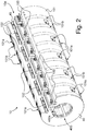
- Figure 2 is a perspective view of a portion of the cylinder body 10.
- a common shaft member has been omitted in this Figure, which common shaft member is described in greater detail in International application No. WO 2008/102303 A2 .
- the cylinder body 10 exhibits an essentially cylindrical outer shape with a clearance 10a extending axially over a length of the cylinder body 10.
- Such clearance 10a may accommodate grippers (not shown) for holding a leading edge of the sheets.
- a cover plate 101 is provided on an outer circumference of the cylinder body 10.
- This cover plate 101 which is made of material exhibiting a low magnetic permeability is advantageously clamped at both extremities in the region of the clearance 10a.
- Clamping means 102, 103 are provided for this purpose, which clamping means are designed to secure the cover plate 101 in an adequate manner on the outer circumference of the cylinder body 10.
- the cover plate 101 is clamped at one end by first clamping bars 102 and at the other end by second clamping bars 103. While this is not shown in detail, the second clamping bars 103 are designed to be displaceable on the cylinder body 10 so as to adjust the tension of the cover plate 101.
- the cover plate 101 is provided in this example with a plurality of rectangular openings 101 a.
- the positions of these openings 101 a is made to correspond to the positions of below-located magnetic-field-inducing devices.
- the openings 101 a are as such optional and are preferable in case use is made of a particular type of magnetic-field-inducing devices, such as those described in WO 2005/002866 A1 which are to be disposed preferably in close proximity with the ink/varnish pattern containing the magnetic flakes to be oriented. With other types of magnetic-field-inducing devices, one might omit the openings 101 a.
- a plurality of small openings 101 b visible on the upper part of Figure 2 are further provided in this example along a plurality of annular lines shown as dashed lines in the lower part of Figure 2 . As described in International application No. WO 2008/102303 A2 , these openings 101 b communicate with a plurality of suction outlets located below the cover plate 101 and designed to permit aspiration of the processed sheet against the circumference of the cylinder body 10.
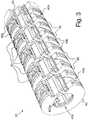
- FIG 3 is a view of part of the cylinder body 10 illustrated in Figure 2 without the cover plate 101.
- the cylinder body 10 comprises a plurality of annular supporting rings 40 distributed axially along the axis of rotation of the cylinder body 10.
- five identical annular supporting rings 40 are provided.
- An additional ring 45 is provided at the outermost right extremity of the cylinder body 10. This additional ring 45 essentially fulfils the function of supporting the right-hand side of the cover plate 101 shown in Figure 2 and provides symmetry to the overall cylinder body 10.
- Each annular supporting ring 40 is preferably provided with a peripheral mounting groove 40a and a pair of peripheral supporting shoulders 40b extending on each side of the annular mounting groove 40a.
- a plurality of supporting members 50 are mounted on the peripheral mounting groove 40a, which supporting members 50 are designed to receive a corresponding magnetic-field-inducing element (not shown).
- Such magnet-field-inducing element can be as simple as a permanent magnet as illustrated in Figure 4 of International application WO 2005/000585 A1 or a device comprising a body of permanent magnetic material the surface of which is engraved to cause perturbations of its magnetic field as discussed in International application WO 2005/002866 A1 .
- the magnet-field-generating devices can be any type of device susceptible of producing a magnetic field capable of orienting the magnetic flakes contained in the ink/varnish patterns applied on the substrate to be processed, such as electro-magnets.
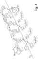
- Figure 4 is a schematic illustration of the said supporting members 50 according to a possible mounting configuration about the axis of rotation O of the cylinder body 10.
- all the other elements of the cylinder body 10 have been omitted so as to show all the supporting members 50 in their mounting positions.
- eight supporting members 50 are provided on each annular supporting ring 40, thus totalling forty supporting members 50, each designed to form a corresponding magnetic-field-inducing device for cooperation with a corresponding one of forty different locations on the sheets being processed.
- the resulting cylinder body is adapted for cooperation with sheets on the surface of which an array of forty magnetic-flakes-containing patterns arranged in a matrix of five columns and eight rows has been printed. Such arrangement is obviously purely illustrative and other arrangements might be envisaged.
- peripheral supporting shoulders 40b have a diameter such that the supporting members 50 (and accordingly the magnetic-field-inducing devices as well) are almost completely enclosed between the supporting shoulders 40b.
- the supporting shoulders 40b are designed to provide a support on each side of the magnetic-field-inducing devices, along the axis of rotation of the cylinder body 10.
- the peripheral mounting groove 40a preferably exhibits an inverted-T shape for insertion of the supporting members 50.
- Each supporting member 50 exhibits a corresponding T-shape matching that of the peripheral mounting groove 40a.
- Each supporting member 50 is preferably provided with its own clamping element 51 (visible in Figure 4 ) adapted for cooperation with the peripheral mounting groove 40a of the annular supporting rings 40 for securing the magnetic-field-inducing devices in place at any desired position along the peripheral mounting groove 40a. In this way, each magnetic-field-inducing device can be adjusted freely along the circumference of the annular supporting rings 40, independently of the other magnetic-field-inducing devices disposed on the same annular supporting ring 40.
- each ring 40 (and 45) comprises an inner mounting groove 400a extending parallel to the axis of rotation O of the cylinder body 10.
- This inner mounting groove 400a is designed to enable mounting on the rings 40, 45 at a determined angular position about the common shaft member.
- a mounting bar (not shown) is secured to a longitudinal portion of the common shaft member, which mounting bar cooperates with the inner mounting grooves 400a of the annular supporting rings 40. In this way, each annular supporting ring 40 is precisely positioned with respect to the common shaft member and according to a same common angular reference position.
- each annular supporting ring 40 is freely adjustable along the axis of the common shaft member, independently of the other annular supporting rings 40.
- FIG 6 is a schematic side view illustrating the cooperation of the cylinder body 10 with the path P of the sheets in Figure 5 .
- sheets are being transferred, with the freshly-printed side (where the ink or varnish vehicle containing the magnetic flakes is applied) oriented upwards, to the cylinder body 10 by the upstream-located chain conveyor system 31 (not shown in Figure 6 but located on the right-hand side of the cylinder body 10 in Figure 6 ) and then taken away from the cylinder body 10 by the downstream-located chain conveyor system 32 (not shown in Figure 6 but located on the left-hand side of the cylinder body 10 in Figure 6 ).
- the sheets therefore follow a curved path P (from right to left in Figures 5 and 6 ) about the outer circumference of the cylinder body 10, which cylinder body 10 is made to rotate around its axis of rotation O (in a counterclockwise direction as illustrated by the arrow in Figure 6 ) in synchronism with the displacement of the sheets and the movement of the gripper bars of the chain conveyor systems 31, 32. More precisely, the cylinder body 10 is provided with grippers (not shown) to hold a leading edge of the sheets.
- the cylinder body 10 When a new sheet is arriving, the cylinder body 10 is positioned in such a way that the grippers thereof are brought in the vicinity of the gripper bar of the upstream-located chain gripper system 31 to allow transfer of the corresponding sheet onto the circumference of the cylinder body 10 in a manner known as such in the art. Transfer of the sheet from the cylinder body 10 to the downstream-located chain conveyor system 32 is made in a similar way.
- Line A in Figure 6 schematically designates the location where the sheet is transferred to the cylinder body 10 from the upstream-located chain conveyor system 31.
- line B in Figure 6 schematically designates the location where the sheet is taken away form the cylinder body 10 and transferred to the downstream-located chain conveyor system 32.
- Lines A and B delimit an angular sector S along the circumference of the cylinder body 10 where each sheet is being brought into contact with (or at least in close proximity to) the outer circumference of the cylinder body 10.
- This angular sector S defines the region where orientation of the magnetic flakes is carried out. While the angular sector S shown in Figure 6 is smaller than 180°, this shall only be considered to be illustrative.
- the angular sector S way alternately chosen to be as wide as possible, especially greater than 180°.
- At least one drying or curing unit 60 is provided in the vicinity of the processing unit 10* for drying or curing the ink or varnish vehicle to fix the orientation of the magnetic flakes contained therein while the substrate is still in contact with or in close proximity to the processing unit 10* (and the magnetic-field-inducing devices) before the substrate is taken away from the magnetic-field-inducing devices.
- the drying or curing unit 60 is located proximate to the outer circumference of the cylinder body 10 at a downstream end of the angular sector S.
- the drying or curing of the ink or varnish vehicle does not necessarily need to be complete, i.e. it may suffice to partly dry or induce partial curing of the ink or varnish vehicle to prevent the flakes from moving too much during separation of the substrate from the processing unit. In that respect, it may still be necessary to provide an additional drying or curing unit 5 along the path of the sheet downstream of the processing unit 10* as shown in Figure 5 .
- the drying or curing unit 60 may be of a type suitable to dry or cure almost completely the ink or varnish vehicle, without there being a need anymore for an additional drying or curing unit 5.
- the drying or curing unit 60 may be of any suitable type. It is however preferred and advantageous to use a UV-curing unit, i.e. a unit suitable for applying UV radiation to the substrate (provided the ink or varnish vehicle is a UV-curable ink or varnish vehicle).
- a UV-curing unit i.e. a unit suitable for applying UV radiation to the substrate (provided the ink or varnish vehicle is a UV-curable ink or varnish vehicle).
- the drying or curing unit 60 may include LED elements, preferably LED elements producing radiation in the UV range (or "UV-LED curing elements").
- LED elements may conveniently be arranged in the form of a longitudinal bar extending transversely to the path of the substrate.
Description
- The present invention generally relates to a sheet-fed printing press and process for orienting magnetic flakes contained in an ink or varnish vehicle applied on a sheet-like substrate. The present invention is especially applicable and usable in the context of the production of security documents, such as banknotes.
- A printing press comprising a cylinder body for orienting magnetic flakes is known as such in the art. Such a printing press is for instance disclosed in International application No.
WO 2005/000585 A1 filed in the name of the present Applicant. - One embodiment of a sheet-fed printing press disclosed in International application No.
WO 2005/000585 A1 is represented inFigure 1 . This printing press is adapted to print sheets according to the silk-screen printing process and comprises afeeding station 1 for feeding successive sheets to a silk-screen printing group 2 where silk-screen patterns are applied onto the sheets. In this example theprinting group 2 comprises animpression cylinder 2a cooperating with twoscreen cylinders printing group 2, the freshly printed sheets are transported by means of aconveyor system 3 to adelivery station 4 comprising a plurality of delivery pile units, three in this example. Theconveyor system 3 is typically an endless chain conveyor system comprising a plurality of spaced-apart gripper bars (not shown inFigure 1 ) extending transversely to the sheet transporting direction, each gripper bar comprising grippers for holding a leading edge of the sheets. - In the example illustrated in
Figure 1 , aprocessing unit 10* comprising acylinder 10 carrying a plurality of magnetic-field-inducing devices is located along the path of the sheets carried by thechain conveyor system 3. Thiscylinder 10 is designed to apply a magnetic field to selected locations of the sheets for the purpose of orienting magnetic flakes contained in the patterns of ink or varnish which have been freshly-applied on the sheets in theprinting group 2. A drying orcuring unit 5 is provided downstream of thecylinder 10 for drying, respectively curing, the ink/varnish applied onto the sheets after the magnetic flakes have been oriented,such unit 5 being typically an infrared drying unit or a UV curing unit depending on the type of ink or varnish used. - An improved cylinder configuration forms the subject-matter of International application No.
WO 2008/102303 A2 in the name of the present Applicant. - Further details regarding silk-screen printing presses, including relevant details of the silk-screen printing press illustrated in
Figure 1 , can be found in European patent applications Nos.EP 0 723 864 A1 ,EP 0 769 376 A1 and in International applications Nos.WO 97/29912 A1 WO 97/34767 A1 WO 03/093013 A2 WO 2004/096545 A2 ,WO 2005/095109 A1 andWO 2005/102699 A1 . - Silk-screen printing is in particular adopted, in the context of the production of security documents, such as banknotes, to print optically-variable patterns onto the documents, including so-called iridescent patterns and OVI® patterns (OVI® is a registered trademark of SICPA Holding SA, Switzerland). Such patterns are printed using inks or varnishes containing special pigments or flakes producing optically variable effects.
- So-called "magnetic flakes" are also known in the art, which flakes have the particularity that they can be oriented or aligned by an appropriately-applied magnetic field. While the terminology "magnetic flakes" is used, it should be understood that this terminology designates flakes that can be oriented using a magnetic field, including flakes that are not necessarily magnetic per se but are capable of being oriented using a magnetic field. Such magnetic flakes and method for orienting such magnetic flakes are discussed in particular in US Patent No.
US 4,838,648 , European patent application No.EP 0 686 675 A1 , and International applications Nos.WO 02/073250 A2 WO 03/000801 A2 WO 2004/007095 A2 ,WO 2004/007096 A2 ,WO 2005/002866 A1 . - The most convenient method to apply the above magnetic flakes is by silk-screen printing as discussed in the above-mentioned International application
WO 2005/000585 A1 . This is mainly due to the fact that the flakes have a relatively important size which restricts the choice of available printing processes for applying inks or varnishes containing such flakes. In particular, one has to ensure that the flakes are not destroyed or damaged during the printing process, and silk-screen printing constitutes the most convenient printing process to achieve this goal. Furthermore, silk-screen printing has the advantage that relatively thick layers of ink or varnish can be applied. Furthermore, the inks or varnishes used in silk-screen printing exhibit a relatively low viscosity which favours proper orientation of the magnetic flakes. - Nevertheless, other printing processes could be envisaged to apply inks and varnishes containing magnetic flakes. In European
patent application EP 1 650 042 A1 , it is for instance proposed to apply such magnetic flakes in an intaglio printing process, whereby the paste-like intaglio ink containing the flakes is heated to decrease the viscosity of the ink and thereby allow the flakes to be oriented more easily. This can be performed in a conventional intaglio printing press, since the plate cylinder of such presses is commonly brought to an operating temperature of approximately 80 °C during printing operations. - Orientation of the magnetic flakes is carried out by applying an adequate magnetic field to the freshly-applied ink or varnish containing the magnetic flakes. By appropriately shaping the field lines of the magnetic field, as for instance discussed in the above-mentioned patent publications, the magnetic flakes can be aligned in any desired pattern producing a corresponding optically-variable effect which is very difficult, if not impossible to counterfeit.
- As already mentioned hereinabove, an adequate solution for orienting the magnetic flakes consists in bringing the sheets in contact with a rotating cylinder carrying a plurality of magnetic-field-inducing devices.
- Referring again to
Figure 1 , and as discussed in International application No.WO 2005/000585 A1 , thecylinder 10 could alternatively be located at thesheet transfer location 3a between theimpression cylinder 2a and theconveyor system 3. Still according to another embodiment envisaged in International application No.WO 2005/000585 A1 , theimpression cylinder 2a itself could be designed as a cylinder carrying magnetic-field-inducing devices. - In the embodiment illustrated in
Figure 1 , thecylinder 10 used to orient the magnetic flakes advantageously cooperates with the non-freshly-printed side of the sheets, thereby preventing smearing problems, the magnetic field being applied from the back side of the sheets through the freshly-printed patterns of ink or varnish. During orientation of the magnetic flakes, i.e. at the time when a sheet carried by theconveyor system 3 contacts the upper part of the circumference of thecylinder 10, thecylinder 10 is rotated at a circumferential speed corresponding to the speed of the transported sheets so that there is no relative displacement between the transported sheets and the circumference of the cylinder. As illustrated, thecylinder 10 is placed in the path of thechain conveyor system 3 such that the sheets follow a curved path tangential to the outer circumference of thecylinder 10, thereby enabling part of the surface of the processed sheet to be brought in contact with the outer circumference of thecylinder 10. - In the context of the production of banknotes, in particular, each printed sheet (or each successive portion of a continuous web, in case of web-printing) carries an array of imprints arranged in a matrix of rows and columns, which imprints ultimately form individual securities after final cutting of the sheets or web portions. The cylinder used to orient the magnetic flakes is therefore typically provided with as many magnetic-field-inducing devices as there are imprints on the sheets or web portions.
- As illustrated in
Figure 1 , drying or curing of the ink or varnish vehicle is performed downstream of thecylinder 10 by means of a suitable drying or curingunit 5, i.e. after the substrate has been taken away from theprocessing unit 10* where orientation of the magnetic flakes is being carried out. - Tests have shown that the separation of the substrate from the
processing unit 10* where orientation of the flakes is carried out may cause undesired effects on the resulting orientation of the flakes as such separation necessarily leads to a modification of the magnetic field applied to the substrate. - One solution to this problem may consist in using electro-magnets to act as the magnetic-field-inducing devices and sequentially interrupting the applied magnetic field, row after row, before the substrate is separated from the processing unit, but this is costly solution (compared to the use of permanent magnets) and may not ultimately solve all issues as the shutting down of the electro-magnets may also affect the orientation of the flakes contained in the ink or varnish vehicle applied on the substrate.
- There is therefore a need for an improved solution to cope with the above-mentioned problem.
- A general aim of the invention is therefore to improve the known systems and processes.
- More specifically an aim of the present invention is to provide a solution that ensures that separation of the substrate from the processing unit where orientation of the magnetic flakes contained in the ink or varnish vehicle is carried out has as little effect as possible on the resulting optical effect to be induced in the layer of ink or varnish applied on the substrate..
- Still another aim of the present invention is to provide a solution that can suitably be integrated in a practical system, especially in a printing press.
- These aims are achieved thanks to the solution defined in the claims.
- There is accordingly provided a printing press as defined in
claim 1, namely a sheet-fed printing press comprising a printing group designed to apply an ink or varnish vehicle containing magnetic flakes on a sheet-like substrate and a system designed to orient the magnetic flakes contained in the ink or varnish vehicle applied on the substrate, which system comprises a processing unit with at least one magnetic-field-inducing device for orienting the magnetic flakes contained in the ink or varnish vehicle applied on the substrate, which processing unit is located along a path of the substrate in such a way that the substrate is brought into contact with or in close proximity to the processing unit and the said at least one magnetic-field-inducing device. The processing unit comprises a cylinder body, the at least one magnetic-field-inducing device being disposed on an outer circumference of the cylinder body. The printing press further comprises a first chain conveyor system designed to transport and transfer the substrate to the processing unit and a second chain conveyor system designed to take away the substrate from the processing unit. The system further comprises at least one drying or curing unit disposed in the vicinity of the cylinder body for drying or curing the ink or varnish vehicle to fix the orientation of the magnetic flakes contained therein while the substrate is still in contact with or in close proximity to the cylinder body and the said at least one magnetic-field-inducing device before the substrate is taken away from the said at least one magnetic-field-inducing device. - There is also provided a process as defined in
claim 10, namely a process for orienting magnetic flakes contained in an ink or varnish vehicle applied on a sheet-like substrate, which process includes the following steps : - (a) printing the ink or varnish vehicle containing the magnetic flakes on the substrate ;
- (b) transporting the substrate by means of a first chain conveyor system to a processing unit comprising a cylinder body carrying at least one magnetic-field-inducing device for orienting the magnetic flakes contained in the ink or varnish vehicle applied on the substrate, which at least one magnetic-field-inducing device is disposed on an outer circumference of the cylinder body ;
- (c) transferring the substrate from the first chain conveyor system to the processing unit and bringing the substrate into contact with or in close proximity to the cylinder body carrying the said at least one magnetic-field-inducing device, and
- (d) drying or curing the ink or varnish vehicle to fix the orientation of the magnetic flakes contained therein,
- (e) transferring the substrate to a second chain conveyor system designed to take away the substrate from the processing unit.
- In this context, the substrate is advantageously brought into contact with or in close proximity to the outer circumference of the cylinder body over a selected angular sector and the said at least one drying or curing unit is located proximate to the outer circumference of the cylinder body at a downstream end of the selected angular sector.
- In the context of the invention, the processing unit may comprise a plurality of magnetic-field-inducing devices distributed in a matrix-like arrangement for orienting the magnetic flakes contained in a plurality of ink or varnish patterns applied on the substrate in a corresponding matrix-like arrangement. In the case of a cylinder body as mentioned above, the plurality of magnetic-field-inducing devices would be distributed on the outer circumference of the cylinder body.
- Preferably, the said at least one drying or curing unit is a UV-curing unit, i.e. a unit capable of applying UV radiation to the substrate, to induce polymerisation of the ink or varnish vehicle.
- Advantageously, use can be made of LED elements, preferably LED elements producing radiation in the UV range. Such LED elements may conveniently be arranged in the form of a longitudinal bar extending transversely to the path of the substrate.
- Advantageous embodiments of the invention form the subject-matter of the dependent claims and are discussed below.
- Other features and advantages of the present invention will appear more clearly from reading the following detailed description of embodiments of the invention which are presented solely by way of non-restrictive examples and illustrated by the attached drawings in which:
-
Figure 1 is a side view of a sheet-fed silk-screen printing press incorporating a processing unit for orienting magnetic flakes contained in an ink or varnish vehicle, which processing unit comprises a cylinder body; -
Figure 2 is a schematic perspective view of a portion of a suitable cylinder body for orienting the magnetic flakes; -
Figure 3 is a schematic perspective view of annular supporting rings forming part of the cylinder body illustrated inFigure 2 ; -
Figure 4 is a schematic perspective view illustrating the arrangement of the magnetic-field-inducing devices carried by the cylinder body ofFigures 2 and3 about the axis of rotation of the cylinder body shown by a dashed line; -
Figure 5 is a side view of a sheet-fed silk-screen printing press incorporating a system according to the invention, including a processing unit comprising a cylinder body; and -
Figure 6 is a schematic side view illustrating the cooperation of the processing unit shown inFigure 5 with the path of the substrate, and wherein a drying or curing unit is further provided proximate to the processing unit. - The invention will be described hereinafter in the context of a sheet-fed silk-screen printing press for printing security papers, in particular banknotes. The silk-screen printing press may be a printing press as illustrated in
Figure 5 . The illustrated embodiment shows a processing unit (hereinafter designated byreference numeral 10*) of the type having a cylinder body which is in particular adapted for cooperation with a chain conveyor system of the type comprising a plurality of spaced-apart grippers bars as already discussed hereinabove. The invention is equally applicable to any other cylinder configuration that could be installed between the printing group of a silk-screen printing press and thedelivery station 4. For instance, according to a possible alternate embodiment of the invention, the cylinder body could be part of a processing unit comprising a plurality of processing cylinders each with its own sheet grippers. In other words, while the illustrated embodiment shows a cylinder body adapted for cooperating with a chain conveyor system, this shall not as such be regarded as an aspect limiting the scope of the invention. - In accordance with the present invention, the printing press is provided with (see
Figure 5 ) a firstchain conveyor system 31 located upstream of theprocessing unit 10* for transporting the sheets to theprocessing unit 10* and transferring the sheets to the cylinder body 10 (in which case the cylinder body would comprises its own grippers for taking hold of a leading edge of the sheets) and a secondchain conveyor system 32 located downstream of theprocessing unit 10* for taking the sheets away from theprocessing unit 10* to thedelivery station 4. -
Figure 5 shows a side view of a sheet-fed silk-screen printing press incorporating a system according to the invention, including aprocessing unit 10* comprising acylinder body 10. The same reference numerals as inFigure 1 are used inFigure 5 to designate the same elements which do not require any further explanation. It suffices to understand that the main difference between the printing presses ofFigure 5 and ofFigure 1 resides in the fact that twochain conveyor systems processing unit 10* are provided in the embodiment ofFigure 5 , rather than only one. More precisely, a firstchain conveyor system 31 is located upstream of theprocessing unit 10*, while a secondchain conveyor system 32 is located downstream of theprocessing unit 10*. -
Figures 2 to 4 illustrate a possible, and preferred, embodiment of theprocessing unit 10* comprising acylinder body 10 of the same type as disclosed in International application No.WO 2008/102303 A2 . -
Figure 2 is a perspective view of a portion of thecylinder body 10. A common shaft member has been omitted in this Figure, which common shaft member is described in greater detail in International application No.WO 2008/102303 A2 . - As shown in
Figure 2 , thecylinder body 10 exhibits an essentially cylindrical outer shape with aclearance 10a extending axially over a length of thecylinder body 10.Such clearance 10a may accommodate grippers (not shown) for holding a leading edge of the sheets. In this preferred example, acover plate 101 is provided on an outer circumference of thecylinder body 10. Thiscover plate 101, which is made of material exhibiting a low magnetic permeability is advantageously clamped at both extremities in the region of theclearance 10a. Clamping means 102, 103 are provided for this purpose, which clamping means are designed to secure thecover plate 101 in an adequate manner on the outer circumference of thecylinder body 10. More precisely, thecover plate 101 is clamped at one end by first clamping bars 102 and at the other end by second clamping bars 103. While this is not shown in detail, the second clamping bars 103 are designed to be displaceable on thecylinder body 10 so as to adjust the tension of thecover plate 101. - As further illustrated in
Figure 2 , thecover plate 101 is provided in this example with a plurality ofrectangular openings 101 a. The positions of theseopenings 101 a is made to correspond to the positions of below-located magnetic-field-inducing devices. Theopenings 101 a are as such optional and are preferable in case use is made of a particular type of magnetic-field-inducing devices, such as those described inWO 2005/002866 A1 which are to be disposed preferably in close proximity with the ink/varnish pattern containing the magnetic flakes to be oriented. With other types of magnetic-field-inducing devices, one might omit theopenings 101 a. - A plurality of
small openings 101 b visible on the upper part ofFigure 2 are further provided in this example along a plurality of annular lines shown as dashed lines in the lower part ofFigure 2 . As described in International application No.WO 2008/102303 A2 , theseopenings 101 b communicate with a plurality of suction outlets located below thecover plate 101 and designed to permit aspiration of the processed sheet against the circumference of thecylinder body 10. -
Figure 3 is a view of part of thecylinder body 10 illustrated inFigure 2 without thecover plate 101. As this is visible inFigure 3 , thecylinder body 10 comprises a plurality of annular supporting rings 40 distributed axially along the axis of rotation of thecylinder body 10. In the illustrated example, five identical annular supporting rings 40 are provided. Anadditional ring 45 is provided at the outermost right extremity of thecylinder body 10. Thisadditional ring 45 essentially fulfils the function of supporting the right-hand side of thecover plate 101 shown inFigure 2 and provides symmetry to theoverall cylinder body 10. - Each annular supporting
ring 40 is preferably provided with a peripheral mountinggroove 40a and a pair of peripheral supportingshoulders 40b extending on each side of the annular mountinggroove 40a. A plurality of supportingmembers 50 are mounted on the peripheral mountinggroove 40a, which supportingmembers 50 are designed to receive a corresponding magnetic-field-inducing element (not shown). - Such magnet-field-inducing element can be as simple as a permanent magnet as illustrated in
Figure 4 of International applicationWO 2005/000585 A1 or a device comprising a body of permanent magnetic material the surface of which is engraved to cause perturbations of its magnetic field as discussed in International applicationWO 2005/002866 A1 . Within the scope of the present invention, the magnet-field-generating devices can be any type of device susceptible of producing a magnetic field capable of orienting the magnetic flakes contained in the ink/varnish patterns applied on the substrate to be processed, such as electro-magnets. -
Figure 4 is a schematic illustration of the said supportingmembers 50 according to a possible mounting configuration about the axis of rotation O of thecylinder body 10. InFigure 4 , all the other elements of thecylinder body 10 have been omitted so as to show all the supportingmembers 50 in their mounting positions. In the illustrated embodiment, one may appreciate that eight supportingmembers 50 are provided on each annular supportingring 40, thus totalling forty supportingmembers 50, each designed to form a corresponding magnetic-field-inducing device for cooperation with a corresponding one of forty different locations on the sheets being processed. According to the illustrated embodiment, one will therefore understand that the resulting cylinder body is adapted for cooperation with sheets on the surface of which an array of forty magnetic-flakes-containing patterns arranged in a matrix of five columns and eight rows has been printed. Such arrangement is obviously purely illustrative and other arrangements might be envisaged. - Referring again to
Figure 3 , one may appreciate that the peripheral supportingshoulders 40b have a diameter such that the supporting members 50 (and accordingly the magnetic-field-inducing devices as well) are almost completely enclosed between the supportingshoulders 40b. In other words, the supportingshoulders 40b are designed to provide a support on each side of the magnetic-field-inducing devices, along the axis of rotation of thecylinder body 10. - As is also apparent from looking at
Figure 3 , the peripheral mountinggroove 40a preferably exhibits an inverted-T shape for insertion of the supportingmembers 50. Each supportingmember 50 exhibits a corresponding T-shape matching that of the peripheral mountinggroove 40a. Each supportingmember 50 is preferably provided with its own clamping element 51 (visible inFigure 4 ) adapted for cooperation with the peripheral mountinggroove 40a of the annular supporting rings 40 for securing the magnetic-field-inducing devices in place at any desired position along the peripheral mountinggroove 40a. In this way, each magnetic-field-inducing device can be adjusted freely along the circumference of the annular supporting rings 40, independently of the other magnetic-field-inducing devices disposed on the same annular supportingring 40. - The annular supporting rings 40 discussed above (as well as the additional ring 45) are mounted on a common shaft member (not shown - see International application No.
WO 2008/102303 A2 ) by way of acentral opening 400 visible inFigures 2 and3 . Preferably, each ring 40 (and 45) comprises aninner mounting groove 400a extending parallel to the axis of rotation O of thecylinder body 10. This inner mountinggroove 400a is designed to enable mounting on therings grooves 400a of the annular supporting rings 40. In this way, each annular supportingring 40 is precisely positioned with respect to the common shaft member and according to a same common angular reference position. - The supporting
members 50 and annular supporting rings 40 are preferably made of aluminium, or any other material exhibiting a low magnetic permeability. Advantageously, each annular supportingring 40 is freely adjustable along the axis of the common shaft member, independently of the other annular supporting rings 40. - Further information about the
cylinder body 10 may be found in International application No.WO 2008/102303 A2 . -
Figure 6 is a schematic side view illustrating the cooperation of thecylinder body 10 with the path P of the sheets inFigure 5 . As mentioned hereinabove, it is to be understood that sheets are being transferred, with the freshly-printed side (where the ink or varnish vehicle containing the magnetic flakes is applied) oriented upwards, to thecylinder body 10 by the upstream-located chain conveyor system 31 (not shown inFigure 6 but located on the right-hand side of thecylinder body 10 inFigure 6 ) and then taken away from thecylinder body 10 by the downstream-located chain conveyor system 32 (not shown inFigure 6 but located on the left-hand side of thecylinder body 10 inFigure 6 ). The sheets therefore follow a curved path P (from right to left inFigures 5 and6 ) about the outer circumference of thecylinder body 10, whichcylinder body 10 is made to rotate around its axis of rotation O (in a counterclockwise direction as illustrated by the arrow inFigure 6 ) in synchronism with the displacement of the sheets and the movement of the gripper bars of thechain conveyor systems cylinder body 10 is provided with grippers (not shown) to hold a leading edge of the sheets. - When a new sheet is arriving, the
cylinder body 10 is positioned in such a way that the grippers thereof are brought in the vicinity of the gripper bar of the upstream-locatedchain gripper system 31 to allow transfer of the corresponding sheet onto the circumference of thecylinder body 10 in a manner known as such in the art. Transfer of the sheet from thecylinder body 10 to the downstream-locatedchain conveyor system 32 is made in a similar way. - Line A in
Figure 6 schematically designates the location where the sheet is transferred to thecylinder body 10 from the upstream-locatedchain conveyor system 31. Similarly, line B inFigure 6 schematically designates the location where the sheet is taken away form thecylinder body 10 and transferred to the downstream-locatedchain conveyor system 32. Lines A and B delimit an angular sector S along the circumference of thecylinder body 10 where each sheet is being brought into contact with (or at least in close proximity to) the outer circumference of thecylinder body 10. This angular sector S defines the region where orientation of the magnetic flakes is carried out. While the angular sector S shown inFigure 6 is smaller than 180°, this shall only be considered to be illustrative. The angular sector S way alternately chosen to be as wide as possible, especially greater than 180°. - According to the invention, at least one drying or curing
unit 60 is provided in the vicinity of theprocessing unit 10* for drying or curing the ink or varnish vehicle to fix the orientation of the magnetic flakes contained therein while the substrate is still in contact with or in close proximity to theprocessing unit 10* (and the magnetic-field-inducing devices) before the substrate is taken away from the magnetic-field-inducing devices. - More precisely, in the particular and preferred embodiment shown in
Figures 5 and6 , the drying or curingunit 60 is located proximate to the outer circumference of thecylinder body 10 at a downstream end of the angular sector S. - In this way, drying or curing of the ink or varnish vehicle can be performed before actual separation of the substrate from the processing unit, thereby avoiding the problems mentioned in the preamble hereof.
- It shall be understood that the drying or curing of the ink or varnish vehicle does not necessarily need to be complete, i.e. it may suffice to partly dry or induce partial curing of the ink or varnish vehicle to prevent the flakes from moving too much during separation of the substrate from the processing unit. In that respect, it may still be necessary to provide an additional drying or curing
unit 5 along the path of the sheet downstream of theprocessing unit 10* as shown inFigure 5 . This being said, the drying or curingunit 60 may be of a type suitable to dry or cure almost completely the ink or varnish vehicle, without there being a need anymore for an additional drying or curingunit 5. - In view of the above considerations, the drying or curing
unit 60 may be of any suitable type. It is however preferred and advantageous to use a UV-curing unit, i.e. a unit suitable for applying UV radiation to the substrate (provided the ink or varnish vehicle is a UV-curable ink or varnish vehicle). - Advantageously, the drying or curing
unit 60 may include LED elements, preferably LED elements producing radiation in the UV range (or "UV-LED curing elements"). Such LED elements may conveniently be arranged in the form of a longitudinal bar extending transversely to the path of the substrate. - Various modifications and/or improvements may be made to the above-described embodiments without departing from the scope of the invention as defined by the annexed claims.
- Furthermore, while silk-screen printing is a preferred printing process for applying the ink/varnish patterns contained the magnetic flakes to be oriented, other printing process might be envisaged, such as the intaglio printing process as discussed in European
patent application EP 1 650 042 A1 . In other words, the present invention can be applied to any suitable printing process and printing press. - Lastly, use may conveniently be made of the solution described in International application No.
WO 2008/139373 A1 in the name of the present Applicant.
Claims (14)
- A sheet-fed printing press comprising a printing group (2) designed to apply an ink or varnish vehicle containing magnetic flakes on a sheet-like substrate and a system designed to orient the magnetic flakes contained in the ink or varnish vehicle applied on the substrate, which system comprises a processing unit (10*) with at least one magnetic-field-inducing device for orienting the magnetic flakes contained in the ink or varnish vehicle applied on the substrate, which processing unit (10*) is located along a path (P) of the substrate in such a way that the substrate is brought into contact with or in close proximity to the processing unit (10*) and the said at least one magnetic-field-inducing device,
wherein the processing unit (10*) comprises a cylinder body (10) and wherein said at least one magnetic-field-inducing device is disposed on an outer circumference of the cylinder body (10),
characterized in that the printing press further comprises a first chain conveyor system (31) designed to transport and transfer the substrate to the processing unit (10*) and a second chain conveyor system (32) designed to take away the substrate from the processing unit (10*),
and in that the system further comprises at least one drying or curing unit (60) disposed in the vicinity of the cylinder body (10) for drying or curing the ink or varnish vehicle to fix the orientation of the magnetic flakes contained therein while the substrate is still in contact with or in close proximity to the cylinder body (10) and the said at least one magnetic-field-inducing device before the substrate is taken away from the said at least one magnetic-field-inducing device. - Printing press according to claim 1, wherein the substrate is brought into contact with or in close proximity to the outer circumference of the cylinder body (10) over a selected angular sector (S) and wherein the said at least one drying or curing unit (60) is located proximate to the outer circumference of the cylinder body (10) at a downstream end of the selected angular sector (S).
- Printing press according to claim 1 or 2, wherein said cylinder body (10) comprises a plurality of magnetic-field-inducing devices distributed on the outer circumference of the cylinder body (10).
- Printing press according to claim 3, wherein the cylinder body (10) further comprises a plurality of distinct annular supporting rings (40) distributed axially along a common shaft member, each annular supporting ring (40) carrying a set of said magnetic-field-inducing devices which are distributed circumferentially on an outer circumference of the annular supporting rings (40), each said annular supporting ring (40) being preferably freely adjustable along the axis of the common shaft member, independently of the other annular supporting rings (40).
- Printing press according to any one of the preceding claims, wherein the processing unit (10*) comprises a plurality of magnetic-field-inducing devices distributed in a matrix-like arrangement for orienting the magnetic flakes contained in a plurality of ink or varnish patterns applied on the substrate in a corresponding matrix-like arrangement.
- Printing press according to any one of the preceding claims, wherein the said at least one drying or curing unit (60) is a UV-curing unit.
- Printing press according to any one of the preceding claims, wherein the said at least one drying or curing unit (60) comprises LED elements, preferably LED elements producing radiation in the UV range.
- Printing press according to claim 7, wherein said LED elements are arranged in the form of a longitudinal bar extending transversely to the path of the substrate.
- Printing press according to any one of the preceding claims, wherein the printing press is a silk-screen printing press.
- Process for orienting magnetic flakes contained in an ink or varnish vehicle applied on a sheet-like substrate, which process includes the following steps :(a) printing the ink or varnish vehicle containing the magnetic flakes on the substrate ;(b) transporting the substrate by means of a first chain conveyor system (31) to a processing unit (10*) comprising a cylinder body (10) carrying at least one magnetic-field-inducing device for orienting the magnetic flakes contained in the ink or varnish vehicle applied on the substrate, which at least one magnetic-field-inducing device is disposed on an outer circumference of the cylinder body (10) ;(c) transferring the substrate from the first chain conveyor system to the processing unit (10*) and bringing the substrate into contact with or in close proximity to the cylinder body (10) carrying the said at least one magnetic-field-inducing device ; and(d) drying or curing the ink or varnish vehicle to fix the orientation of the magnetic flakes contained therein ;characterized in that step (d) is performed while the substrate is still in contact with or in close proximity to the cylinder body (10) and the said at least one magnetic-field-inducing device before the substrate is taken away from the said at least one magnetic-field-inducing device,
and in that step (d) is followed by the step of :(e) transferring the substrate to a second chain conveyor system (32) designed to take away the substrate from the processing unit (10*). - Process according to claim 10, wherein the substrate is brought into contact with or in close proximity to the outer circumference of the cylinder body (10) over a selected angular sector (S) and wherein step (d) includes drying or curing the ink or varnish vehicle containing the magnetic flakes at a downstream end of said selected angular sector (S).
- Process according to claim 10 or 11, wherein step (d) includes applying UV radiation to the substrate.
- Process according to any one of claims 10 to 12, wherein step (d) includes using LED elements, preferably LED elements producing radiation in the UV range, for drying or curing the ink or varnish vehicle.
- Process according to any one of claims 10 to 13, wherein step (a) is carried out by silk-screen printing.
Priority Applications (2)
| Application Number | Priority Date | Filing Date | Title |
|---|---|---|---|
| EP14193754.0A EP2845732B1 (en) | 2010-09-24 | 2010-09-24 | Sheet-fed printing press and process for orienting magnetic flakes contained in an ink or varnish vehicle applied on a sheet-like substrate |
| ES14193754.0T ES2623162T3 (en) | 2010-09-24 | 2010-09-24 | Sheet-fed printing press and method for orienting magnetic scales contained in an ink or varnish vehicle applied on a sheet-shaped substrate |
Applications Claiming Priority (2)
| Application Number | Priority Date | Filing Date | Title |
|---|---|---|---|
| EP14193754.0A EP2845732B1 (en) | 2010-09-24 | 2010-09-24 | Sheet-fed printing press and process for orienting magnetic flakes contained in an ink or varnish vehicle applied on a sheet-like substrate |
| EP10179681.1A EP2433798B1 (en) | 2010-09-24 | 2010-09-24 | System and method for orienting magnetic flakes contained in an ink or varnish vehicle applied on a sheet-like or web-like substrate |
Related Parent Applications (2)
| Application Number | Title | Priority Date | Filing Date |
|---|---|---|---|
| EP10179681.1A Division-Into EP2433798B1 (en) | 2010-09-24 | 2010-09-24 | System and method for orienting magnetic flakes contained in an ink or varnish vehicle applied on a sheet-like or web-like substrate |
| EP10179681.1A Division EP2433798B1 (en) | 2010-09-24 | 2010-09-24 | System and method for orienting magnetic flakes contained in an ink or varnish vehicle applied on a sheet-like or web-like substrate |
Publications (3)
| Publication Number | Publication Date |
|---|---|
| EP2845732A2 EP2845732A2 (en) | 2015-03-11 |
| EP2845732A3 EP2845732A3 (en) | 2015-04-15 |
| EP2845732B1 true EP2845732B1 (en) | 2017-03-22 |
Family
ID=43585701
Family Applications (2)
| Application Number | Title | Priority Date | Filing Date |
|---|---|---|---|
| EP10179681.1A Active EP2433798B1 (en) | 2010-09-24 | 2010-09-24 | System and method for orienting magnetic flakes contained in an ink or varnish vehicle applied on a sheet-like or web-like substrate |
| EP14193754.0A Active EP2845732B1 (en) | 2010-09-24 | 2010-09-24 | Sheet-fed printing press and process for orienting magnetic flakes contained in an ink or varnish vehicle applied on a sheet-like substrate |
Family Applications Before (1)
| Application Number | Title | Priority Date | Filing Date |
|---|---|---|---|
| EP10179681.1A Active EP2433798B1 (en) | 2010-09-24 | 2010-09-24 | System and method for orienting magnetic flakes contained in an ink or varnish vehicle applied on a sheet-like or web-like substrate |
Country Status (2)
| Country | Link |
|---|---|
| EP (2) | EP2433798B1 (en) |
| ES (2) | ES2623162T3 (en) |
Cited By (11)
| Publication number | Priority date | Publication date | Assignee | Title |
|---|---|---|---|---|
| US10180248B2 (en) | 2015-09-02 | 2019-01-15 | ProPhotonix Limited | LED lamp with sensing capabilities |
| WO2019201480A1 (en) | 2018-04-18 | 2019-10-24 | Koenig & Bauer Ag | Cylinder, device and machine for aligning magnetic or magnetisable particles on a web-like or sheet-like substrate |
| WO2019201481A1 (en) | 2018-04-18 | 2019-10-24 | Koenig & Bauer Ag | Devices, machine and method for applying and aligning magnetic or magnetisable particles on a web-type or sheet-type substrate |
| DE102018212429A1 (en) * | 2018-07-25 | 2020-01-30 | Koenig & Bauer Ag | Device for aligning magnetic or magnetizable particles, machine and method for producing optically variable picture elements |
| DE102018212427A1 (en) * | 2018-07-25 | 2020-01-30 | Koenig & Bauer Ag | Machine and method for producing optically variable picture elements on a substrate |
| DE102018212428A1 (en) * | 2018-07-25 | 2020-01-30 | Koenig & Bauer Ag | Device for aligning magnetic or magnetizable particles, machine and method for producing optically variable picture elements |
| DE102018127936A1 (en) | 2018-11-08 | 2020-05-14 | Koenig & Bauer Ag | Device, printing machine and method for producing a security element on a substrate |
| DE102018205882B4 (en) | 2018-04-18 | 2021-08-05 | Koenig & Bauer Ag | Device and machine for aligning magnetic or magnetizable particles on a web or sheet substrate |
| WO2022069107A1 (en) | 2020-10-01 | 2022-04-07 | Koenig & Bauer Ag | Device and method for aligning magnetic or magnetisable particles, and machine for generating optically variable image elements |
| DE102020125727B3 (en) | 2020-10-01 | 2022-04-07 | Koenig & Bauer Ag | Device for aligning magnetic or magnetizable particles and machine for generating optically variable picture elements |
| DE102020125728B3 (en) | 2020-10-01 | 2022-04-07 | Koenig & Bauer Ag | Device for aligning magnetic or magnetizable particles and machine for generating optically variable picture elements |
Families Citing this family (23)
| Publication number | Priority date | Publication date | Assignee | Title |
|---|---|---|---|---|
| CN103192591B (en) * | 2013-04-10 | 2015-10-21 | 中国人民银行印制科学技术研究所 | Magnetic orientation cylinder and printing machine |
| DE102013015277B4 (en) | 2013-09-16 | 2016-02-11 | Schwarz Druck GmbH | Orientation of magnetically orientable particles in one color with several superimposed magnetic fields |
| EP3077126B1 (en) | 2013-12-04 | 2019-09-18 | Sicpa Holding SA | Devices for producing optical effect layers |
| EP2902210A1 (en) | 2014-02-04 | 2015-08-05 | KBA-NotaSys SA | Multicolour letterpress printing press having numbering cylinders and an additional printing unit |
| TW201605655A (en) | 2014-07-29 | 2016-02-16 | 西克帕控股有限公司 | Processes for in-field hardening of optical effect layers produced by magnetic-field generating devices generating concave field lines |
| AU2015306179A1 (en) | 2014-08-22 | 2016-12-22 | Sicpa Holding Sa | Apparatus and method for producing optical effect layers |
| KR102047985B1 (en) * | 2014-08-26 | 2019-11-22 | 케이비에이-노타시스 에스에이 | Combined printing press |
| WO2016038572A1 (en) | 2014-09-12 | 2016-03-17 | Kba-Notasys Sa | Combined printing press |
| EP3015266A1 (en) | 2014-10-30 | 2016-05-04 | KBA-NotaSys SA | Printing press comprising a magnetic orientation unit and a movable drying/curing unit |
| JP6401628B2 (en) * | 2015-02-23 | 2018-10-10 | リョービMhiグラフィックテクノロジー株式会社 | Printer |
| TW201703879A (en) | 2015-06-02 | 2017-02-01 | 西克帕控股有限公司 | Processes for producing optical effects layers |
| KR102464403B1 (en) | 2017-01-31 | 2022-11-07 | 시크파 홀딩 에스에이 | Apparatus and method for creating an optical effect layer |
| DE102017202747B3 (en) | 2017-02-21 | 2018-08-16 | Koenig & Bauer Ag | Process for processing printing material sheets in the production of securities and securities printing machine |
| DE102017112015A1 (en) * | 2017-05-31 | 2018-12-06 | Heinatz GmbH | Apparatus and methods for magnetic printing and printed matter |
| EP3470227A1 (en) * | 2017-10-13 | 2019-04-17 | Argos Solutions SCRL | Method and device for coating individual sheets |
| DE102018205883A1 (en) | 2018-04-18 | 2019-10-24 | Koenig & Bauer Ag | Device and machine for aligning magnetic or magnetizable particles on a web or sheet substrate |
| WO2020020507A1 (en) * | 2018-07-25 | 2020-01-30 | Koenig & Bauer Ag | Devices for aligning magnetic or magnetizable particles, machine and method for generating optically variable image elements |
| DE102018122146A1 (en) | 2018-09-11 | 2020-03-12 | Koenig & Bauer Ag | Simultaneous sheet printing unit and a sheet printing machine |
| DE102020102621A1 (en) | 2020-02-03 | 2021-08-05 | Koenig & Bauer Ag | Sheet-fed printing machine arrangement with at least two different printing units arranged one after the other in the transport direction of the sheets |
| CN111516372B (en) * | 2020-05-09 | 2021-12-14 | 成都印钞有限公司 | Device capable of realizing screen printing of colorful light columns on winding drum and printing machine |
| CN111823702B (en) * | 2020-06-24 | 2021-08-06 | 江苏睿信印染机械有限公司 | Cross texture cloth silk screen printing device |
| CN115139674B (en) * | 2021-11-17 | 2024-02-23 | 山东泰宝防伪制品有限公司 | Raised substitution process |
| WO2023198300A1 (en) * | 2022-04-13 | 2023-10-19 | Koenig & Bauer Ag | Cylinder for aligning magnetic or magnetizable particles, system for mounting and/or positioning magnetic elements on the cylinder, and machine for generating optically variable image elements |
Family Cites Families (31)
| Publication number | Priority date | Publication date | Assignee | Title |
|---|---|---|---|---|
| FR1336766A (en) * | 1962-07-23 | 1963-09-06 | Rotary machine for the complete printing of fiduciary papers in general and banknotes in particular | |
| US3506467A (en) * | 1966-12-12 | 1970-04-14 | Francis S Ulrich | Applying a protective film to unset printing ink on backing material |
| DE3040388A1 (en) * | 1980-10-25 | 1982-10-07 | M.A.N.- Roland Druckmaschinen AG, 6050 Offenbach | SHEET PRINTING MACHINE WITH AT LEAST ONE PRINTING UNIT FOR BEAUTIFUL AND REPRINTING |
| US4838648A (en) | 1988-05-03 | 1989-06-13 | Optical Coating Laboratory, Inc. | Thin film structure having magnetic and color shifting properties |
| DE4419173A1 (en) | 1994-06-01 | 1995-12-07 | Basf Ag | Magnetizable multi-coated metallic gloss pigments |
| AU696709B2 (en) | 1995-01-24 | 1998-09-17 | Kba-Notasys Sa | Rotary screen printing machine for sheet printing |
| RU2157764C2 (en) | 1995-10-20 | 2000-10-20 | Де ля Рю Жиори С.А. | Sheet-fed machine |
| JP4023629B2 (en) | 1996-02-19 | 2007-12-19 | カーベーアー−ジオリ ソシエテ アノニム | Impression cylinder for sheet-fed printing machine |
| KR100453836B1 (en) | 1996-03-21 | 2004-12-30 | 드라루지오리에쓰.에이. | Screen printer |
| CA2232695C (en) * | 1997-04-14 | 2005-02-01 | De La Rue Giori S.A. | Intaglio printing press |
| US7047883B2 (en) | 2002-07-15 | 2006-05-23 | Jds Uniphase Corporation | Method and apparatus for orienting magnetic flakes |
| EP1239307A1 (en) | 2001-03-09 | 2002-09-11 | Sicpa Holding S.A. | Magnetic thin film interference device |
| US20020160194A1 (en) | 2001-04-27 | 2002-10-31 | Flex Products, Inc. | Multi-layered magnetic pigments and foils |
| DE10219845C1 (en) | 2002-05-03 | 2003-11-20 | Koenig & Bauer Ag | Screen printing machine and screen cylinder |
| US8211509B2 (en) | 2002-07-15 | 2012-07-03 | Raksha Vladimir P | Alignment of paste-like ink having magnetic particles therein, and the printing of optical effects |
| US7258900B2 (en) | 2002-07-15 | 2007-08-21 | Jds Uniphase Corporation | Magnetic planarization of pigment flakes |
| US7399982B2 (en) | 2003-01-09 | 2008-07-15 | Con-Trol-Cure, Inc | UV curing system and process with increased light intensity |
| DE10319773B4 (en) | 2003-05-02 | 2006-04-20 | Koenig & Bauer Ag | screen printing cylinder |
| ZA200600078B (en) | 2003-06-30 | 2007-04-25 | Kba Giori Sa | Printing machine |
| EP1493590A1 (en) | 2003-07-03 | 2005-01-05 | Sicpa Holding S.A. | Method and means for producing a magnetically induced design in a coating containing magnetic particles |
| DE102004015700A1 (en) | 2004-03-29 | 2005-11-03 | Platsch Gmbh & Co.Kg | Flat UV light source |
| EP1582349A1 (en) | 2004-03-30 | 2005-10-05 | Kba-Giori S.A. | Printing process and machine |
| EP1588850A1 (en) | 2004-04-22 | 2005-10-26 | Kba-Giori S.A. | Device for mounting and dismounting a doctor blade in a rotary screen printing cylinder |
| AU2007200128B8 (en) | 2006-01-17 | 2013-02-07 | Viavi Solutions Inc. | Apparatus for orienting magnetic flakes |
| CA2574140C (en) | 2006-01-17 | 2015-03-17 | Jds Uniphase Corporation | Apparatus for orienting magnetic flakes |
| DE102007040139A1 (en) | 2006-09-27 | 2008-04-03 | Heidelberger Druckmaschinen Ag | Printing machine has paper transport drum fitted with internal drying system made up of radiation-producing units in groups which are automatically switched off if there is no paper above them on drum |
| EP1961559A1 (en) | 2007-02-20 | 2008-08-27 | Kba-Giori S.A. | Cylinder body for orienting magnetic flakes contained in an ink or varnish vehicle applied on a sheet-like or web-like substrate |
| EP1990208A1 (en) | 2007-05-10 | 2008-11-12 | Kba-Giori S.A. | Device and method for magnetically transferring indica to a coating composition applied to a substrate |
| DE102007028860A1 (en) | 2007-06-22 | 2008-12-24 | Josef Lindthaler | Device for contact exposure of a printing stencil |
| JP2009208463A (en) | 2008-02-06 | 2009-09-17 | Ryobi Ltd | Printing method of printing machine, and printing machine |
| JP2010089341A (en) | 2008-10-07 | 2010-04-22 | Ryobi Ltd | Printing method for printing machine and printing machine |
-
2010
- 2010-09-24 ES ES14193754.0T patent/ES2623162T3/en active Active
- 2010-09-24 EP EP10179681.1A patent/EP2433798B1/en active Active
- 2010-09-24 EP EP14193754.0A patent/EP2845732B1/en active Active
- 2010-09-24 ES ES10179681.1T patent/ES2540864T3/en active Active
Non-Patent Citations (1)
| Title |
|---|
| None * |
Cited By (15)
| Publication number | Priority date | Publication date | Assignee | Title |
|---|---|---|---|---|
| US10180248B2 (en) | 2015-09-02 | 2019-01-15 | ProPhotonix Limited | LED lamp with sensing capabilities |
| US10994302B2 (en) | 2018-04-18 | 2021-05-04 | Koenig & Bauer Ag | Cylinder, device and machine for aligning magnetic or magnetizable particles on a web-like or sheet-like substrate |
| WO2019201480A1 (en) | 2018-04-18 | 2019-10-24 | Koenig & Bauer Ag | Cylinder, device and machine for aligning magnetic or magnetisable particles on a web-like or sheet-like substrate |
| WO2019201481A1 (en) | 2018-04-18 | 2019-10-24 | Koenig & Bauer Ag | Devices, machine and method for applying and aligning magnetic or magnetisable particles on a web-type or sheet-type substrate |
| DE102018205882B4 (en) | 2018-04-18 | 2021-08-05 | Koenig & Bauer Ag | Device and machine for aligning magnetic or magnetizable particles on a web or sheet substrate |
| DE102018205885B4 (en) * | 2018-04-18 | 2021-05-20 | Koenig & Bauer Ag | Cylinder, device and machine for aligning magnetic or magnetizable particles on a web or sheet substrate |
| DE102018212429A1 (en) * | 2018-07-25 | 2020-01-30 | Koenig & Bauer Ag | Device for aligning magnetic or magnetizable particles, machine and method for producing optically variable picture elements |
| DE102018212428A1 (en) * | 2018-07-25 | 2020-01-30 | Koenig & Bauer Ag | Device for aligning magnetic or magnetizable particles, machine and method for producing optically variable picture elements |
| DE102018212427A1 (en) * | 2018-07-25 | 2020-01-30 | Koenig & Bauer Ag | Machine and method for producing optically variable picture elements on a substrate |
| DE102018212429B4 (en) | 2018-07-25 | 2021-12-02 | Koenig & Bauer Ag | Device for aligning magnetic or magnetizable particles, machine and method for generating optically variable picture elements |
| DE102018127936A1 (en) | 2018-11-08 | 2020-05-14 | Koenig & Bauer Ag | Device, printing machine and method for producing a security element on a substrate |
| WO2022069107A1 (en) | 2020-10-01 | 2022-04-07 | Koenig & Bauer Ag | Device and method for aligning magnetic or magnetisable particles, and machine for generating optically variable image elements |
| DE102020125727B3 (en) | 2020-10-01 | 2022-04-07 | Koenig & Bauer Ag | Device for aligning magnetic or magnetizable particles and machine for generating optically variable picture elements |
| DE102020125728B3 (en) | 2020-10-01 | 2022-04-07 | Koenig & Bauer Ag | Device for aligning magnetic or magnetizable particles and machine for generating optically variable picture elements |
| US11858253B2 (en) | 2020-10-01 | 2024-01-02 | Koenig & Bauer Ag | Machine for generating optically variable image elements |
Also Published As
| Publication number | Publication date |
|---|---|
| ES2623162T3 (en) | 2017-07-10 |
| EP2433798B1 (en) | 2015-04-08 |
| EP2845732A3 (en) | 2015-04-15 |
| ES2540864T3 (en) | 2015-07-14 |
| EP2845732A2 (en) | 2015-03-11 |
| EP2433798A1 (en) | 2012-03-28 |
Similar Documents
| Publication | Publication Date | Title |
|---|---|---|
| EP2845732B1 (en) | Sheet-fed printing press and process for orienting magnetic flakes contained in an ink or varnish vehicle applied on a sheet-like substrate | |
| US8813644B2 (en) | Cylinder body for orienting magnetic flakes contained in an ink or varnish vehicle applied on a sheet-like or web-like substrate | |
| US10279582B2 (en) | Combined printing press | |
| US10434807B2 (en) | Combined printing press | |
| CN113490597B (en) | Device and printing press for producing a security element on a substrate | |
| JP6490697B2 (en) | Multicolor letterpress printing machine with numbering cylinder and additional printing unit | |
| EP2025515A1 (en) | Screen printing press | |
| EP3366475A1 (en) | Printing press with in-line casting device for the replication and formation of a micro-optical structure | |
| EP3489029B1 (en) | Printed security element comprising a rainbow feature and method of producing the same | |
| US11926142B2 (en) | Sheet-fed printing unit configured as a screen printing unit | |
| US20230391066A1 (en) | Sheet-fed printing unit configured as a screen printing unit and comprising two base modules | |
| JP2024504205A (en) | Devices for directing magnetic or magnetizable particles and machines for producing optically variable image elements |
Legal Events
| Date | Code | Title | Description |
|---|---|---|---|
| REG | Reference to a national code |
Ref country code: DE Ref legal event code: R079 Ref document number: 602010041041 Country of ref document: DE Free format text: PREVIOUS MAIN CLASS: B41F0023000000 Ipc: B41F0011020000 |
|
| 17P | Request for examination filed |
Effective date: 20141118 |
|
| AC | Divisional application: reference to earlier application |
Ref document number: 2433798 Country of ref document: EP Kind code of ref document: P |
|
| AK | Designated contracting states |
Kind code of ref document: A2 Designated state(s): AL AT BE BG CH CY CZ DE DK EE ES FI FR GB GR HR HU IE IS IT LI LT LU LV MC MK MT NL NO PL PT RO SE SI SK SM TR |
|
| PUAI | Public reference made under article 153(3) epc to a published international application that has entered the european phase |
Free format text: ORIGINAL CODE: 0009012 |
|
| PUAL | Search report despatched |
Free format text: ORIGINAL CODE: 0009013 |
|
| AK | Designated contracting states |
Kind code of ref document: A3 Designated state(s): AL AT BE BG CH CY CZ DE DK EE ES FI FR GB GR HR HU IE IS IT LI LT LU LV MC MK MT NL NO PL PT RO SE SI SK SM TR |
|
| RIC1 | Information provided on ipc code assigned before grant |
Ipc: B05D 3/00 20060101ALI20150310BHEP Ipc: B41F 21/08 20060101ALI20150310BHEP Ipc: B05D 3/06 20060101ALI20150310BHEP Ipc: B41F 15/12 20060101ALI20150310BHEP Ipc: B41M 3/14 20060101ALI20150310BHEP Ipc: B41F 23/04 20060101ALI20150310BHEP Ipc: B41M 7/00 20060101ALI20150310BHEP Ipc: B41F 11/02 20060101AFI20150310BHEP Ipc: B41F 19/00 20060101ALI20150310BHEP Ipc: B41F 15/08 20060101ALI20150310BHEP |
|
| R17P | Request for examination filed (corrected) |
Effective date: 20151013 |
|
| RBV | Designated contracting states (corrected) |
Designated state(s): AL AT BE BG CH CY CZ DE DK EE ES FI FR GB GR HR HU IE IS IT LI LT LU LV MC MK MT NL NO PL PT RO SE SI SK SM TR |
|
| GRAP | Despatch of communication of intention to grant a patent |
Free format text: ORIGINAL CODE: EPIDOSNIGR1 |
|
| INTG | Intention to grant announced |
Effective date: 20161012 |
|
| GRAS | Grant fee paid |
Free format text: ORIGINAL CODE: EPIDOSNIGR3 |
|
| GRAA | (expected) grant |
Free format text: ORIGINAL CODE: 0009210 |
|
| AC | Divisional application: reference to earlier application |
Ref document number: 2433798 Country of ref document: EP Kind code of ref document: P |
|
| AK | Designated contracting states |
Kind code of ref document: B1 Designated state(s): AL AT BE BG CH CY CZ DE DK EE ES FI FR GB GR HR HU IE IS IT LI LT LU LV MC MK MT NL NO PL PT RO SE SI SK SM TR |
|
| REG | Reference to a national code |
Ref country code: GB Ref legal event code: FG4D |
|
| REG | Reference to a national code |
Ref country code: CH Ref legal event code: EP |
|
| REG | Reference to a national code |
Ref country code: AT Ref legal event code: REF Ref document number: 877316 Country of ref document: AT Kind code of ref document: T Effective date: 20170415 |
|
| REG | Reference to a national code |
Ref country code: IE Ref legal event code: FG4D |
|
| REG | Reference to a national code |
Ref country code: SE Ref legal event code: TRGR |
|
| REG | Reference to a national code |
Ref country code: NL Ref legal event code: FP |
|
| REG | Reference to a national code |
Ref country code: DE Ref legal event code: R096 Ref document number: 602010041041 Country of ref document: DE |
|
| REG | Reference to a national code |
Ref country code: ES Ref legal event code: FG2A Ref document number: 2623162 Country of ref document: ES Kind code of ref document: T3 Effective date: 20170710 |
|
| PG25 | Lapsed in a contracting state [announced via postgrant information from national office to epo] |
Ref country code: NO Free format text: LAPSE BECAUSE OF FAILURE TO SUBMIT A TRANSLATION OF THE DESCRIPTION OR TO PAY THE FEE WITHIN THE PRESCRIBED TIME-LIMIT Effective date: 20170622 Ref country code: GR Free format text: LAPSE BECAUSE OF FAILURE TO SUBMIT A TRANSLATION OF THE DESCRIPTION OR TO PAY THE FEE WITHIN THE PRESCRIBED TIME-LIMIT Effective date: 20170623 Ref country code: FI Free format text: LAPSE BECAUSE OF FAILURE TO SUBMIT A TRANSLATION OF THE DESCRIPTION OR TO PAY THE FEE WITHIN THE PRESCRIBED TIME-LIMIT Effective date: 20170322 Ref country code: LT Free format text: LAPSE BECAUSE OF FAILURE TO SUBMIT A TRANSLATION OF THE DESCRIPTION OR TO PAY THE FEE WITHIN THE PRESCRIBED TIME-LIMIT Effective date: 20170322 Ref country code: HR Free format text: LAPSE BECAUSE OF FAILURE TO SUBMIT A TRANSLATION OF THE DESCRIPTION OR TO PAY THE FEE WITHIN THE PRESCRIBED TIME-LIMIT Effective date: 20170322 |
|
| REG | Reference to a national code |
Ref country code: FR Ref legal event code: PLFP Year of fee payment: 8 |
|
| REG | Reference to a national code |
Ref country code: LT Ref legal event code: MG4D |
|
| PG25 | Lapsed in a contracting state [announced via postgrant information from national office to epo] |
Ref country code: LV Free format text: LAPSE BECAUSE OF FAILURE TO SUBMIT A TRANSLATION OF THE DESCRIPTION OR TO PAY THE FEE WITHIN THE PRESCRIBED TIME-LIMIT Effective date: 20170322 |
|
| PG25 | Lapsed in a contracting state [announced via postgrant information from national office to epo] |
Ref country code: RO Free format text: LAPSE BECAUSE OF FAILURE TO SUBMIT A TRANSLATION OF THE DESCRIPTION OR TO PAY THE FEE WITHIN THE PRESCRIBED TIME-LIMIT Effective date: 20170322 Ref country code: CZ Free format text: LAPSE BECAUSE OF FAILURE TO SUBMIT A TRANSLATION OF THE DESCRIPTION OR TO PAY THE FEE WITHIN THE PRESCRIBED TIME-LIMIT Effective date: 20170322 Ref country code: SK Free format text: LAPSE BECAUSE OF FAILURE TO SUBMIT A TRANSLATION OF THE DESCRIPTION OR TO PAY THE FEE WITHIN THE PRESCRIBED TIME-LIMIT Effective date: 20170322 Ref country code: EE Free format text: LAPSE BECAUSE OF FAILURE TO SUBMIT A TRANSLATION OF THE DESCRIPTION OR TO PAY THE FEE WITHIN THE PRESCRIBED TIME-LIMIT Effective date: 20170322 |
|
| PG25 | Lapsed in a contracting state [announced via postgrant information from national office to epo] |
Ref country code: IS Free format text: LAPSE BECAUSE OF FAILURE TO SUBMIT A TRANSLATION OF THE DESCRIPTION OR TO PAY THE FEE WITHIN THE PRESCRIBED TIME-LIMIT Effective date: 20170722 Ref country code: SM Free format text: LAPSE BECAUSE OF FAILURE TO SUBMIT A TRANSLATION OF THE DESCRIPTION OR TO PAY THE FEE WITHIN THE PRESCRIBED TIME-LIMIT Effective date: 20170322 Ref country code: PT Free format text: LAPSE BECAUSE OF FAILURE TO SUBMIT A TRANSLATION OF THE DESCRIPTION OR TO PAY THE FEE WITHIN THE PRESCRIBED TIME-LIMIT Effective date: 20170724 Ref country code: PL Free format text: LAPSE BECAUSE OF FAILURE TO SUBMIT A TRANSLATION OF THE DESCRIPTION OR TO PAY THE FEE WITHIN THE PRESCRIBED TIME-LIMIT Effective date: 20170322 |
|
| REG | Reference to a national code |
Ref country code: DE Ref legal event code: R097 Ref document number: 602010041041 Country of ref document: DE |
|
| PLBE | No opposition filed within time limit |
Free format text: ORIGINAL CODE: 0009261 |
|
| STAA | Information on the status of an ep patent application or granted ep patent |
Free format text: STATUS: NO OPPOSITION FILED WITHIN TIME LIMIT |
|
| PG25 | Lapsed in a contracting state [announced via postgrant information from national office to epo] |
Ref country code: DK Free format text: LAPSE BECAUSE OF FAILURE TO SUBMIT A TRANSLATION OF THE DESCRIPTION OR TO PAY THE FEE WITHIN THE PRESCRIBED TIME-LIMIT Effective date: 20170322 |
|
| 26N | No opposition filed |
Effective date: 20180102 |
|
| PG25 | Lapsed in a contracting state [announced via postgrant information from national office to epo] |
Ref country code: SI Free format text: LAPSE BECAUSE OF FAILURE TO SUBMIT A TRANSLATION OF THE DESCRIPTION OR TO PAY THE FEE WITHIN THE PRESCRIBED TIME-LIMIT Effective date: 20170322 |
|
| PG25 | Lapsed in a contracting state [announced via postgrant information from national office to epo] |
Ref country code: MC Free format text: LAPSE BECAUSE OF FAILURE TO SUBMIT A TRANSLATION OF THE DESCRIPTION OR TO PAY THE FEE WITHIN THE PRESCRIBED TIME-LIMIT Effective date: 20170322 |
|
| REG | Reference to a national code |
Ref country code: IE Ref legal event code: MM4A |
|
| REG | Reference to a national code |
Ref country code: BE Ref legal event code: MM Effective date: 20170930 |
|
| PG25 | Lapsed in a contracting state [announced via postgrant information from national office to epo] |
Ref country code: LU Free format text: LAPSE BECAUSE OF NON-PAYMENT OF DUE FEES Effective date: 20170924 |
|
| PG25 | Lapsed in a contracting state [announced via postgrant information from national office to epo] |
Ref country code: IE Free format text: LAPSE BECAUSE OF NON-PAYMENT OF DUE FEES Effective date: 20170924 |
|
| PG25 | Lapsed in a contracting state [announced via postgrant information from national office to epo] |
Ref country code: BE Free format text: LAPSE BECAUSE OF NON-PAYMENT OF DUE FEES Effective date: 20170930 |
|
| REG | Reference to a national code |
Ref country code: FR Ref legal event code: PLFP Year of fee payment: 9 |
|
| PG25 | Lapsed in a contracting state [announced via postgrant information from national office to epo] |
Ref country code: HU Free format text: LAPSE BECAUSE OF FAILURE TO SUBMIT A TRANSLATION OF THE DESCRIPTION OR TO PAY THE FEE WITHIN THE PRESCRIBED TIME-LIMIT; INVALID AB INITIO Effective date: 20100924 |
|
| REG | Reference to a national code |
Ref country code: AT Ref legal event code: UEP Ref document number: 877316 Country of ref document: AT Kind code of ref document: T Effective date: 20170322 |
|
| PG25 | Lapsed in a contracting state [announced via postgrant information from national office to epo] |
Ref country code: CY Free format text: LAPSE BECAUSE OF FAILURE TO SUBMIT A TRANSLATION OF THE DESCRIPTION OR TO PAY THE FEE WITHIN THE PRESCRIBED TIME-LIMIT Effective date: 20170322 |
|
| PG25 | Lapsed in a contracting state [announced via postgrant information from national office to epo] |
Ref country code: MK Free format text: LAPSE BECAUSE OF FAILURE TO SUBMIT A TRANSLATION OF THE DESCRIPTION OR TO PAY THE FEE WITHIN THE PRESCRIBED TIME-LIMIT Effective date: 20170322 |
|
| PG25 | Lapsed in a contracting state [announced via postgrant information from national office to epo] |
Ref country code: TR Free format text: LAPSE BECAUSE OF FAILURE TO SUBMIT A TRANSLATION OF THE DESCRIPTION OR TO PAY THE FEE WITHIN THE PRESCRIBED TIME-LIMIT Effective date: 20170322 |
|
| PG25 | Lapsed in a contracting state [announced via postgrant information from national office to epo] |
Ref country code: AL Free format text: LAPSE BECAUSE OF FAILURE TO SUBMIT A TRANSLATION OF THE DESCRIPTION OR TO PAY THE FEE WITHIN THE PRESCRIBED TIME-LIMIT Effective date: 20170322 |
|
| PGFP | Annual fee paid to national office [announced via postgrant information from national office to epo] |
Ref country code: NL Payment date: 20230921 Year of fee payment: 14 Ref country code: GB Payment date: 20230920 Year of fee payment: 14 Ref country code: BG Payment date: 20230928 Year of fee payment: 14 Ref country code: AT Payment date: 20230919 Year of fee payment: 14 |
|
| PGFP | Annual fee paid to national office [announced via postgrant information from national office to epo] |
Ref country code: SE Payment date: 20230921 Year of fee payment: 14 Ref country code: FR Payment date: 20230922 Year of fee payment: 14 Ref country code: DE Payment date: 20230905 Year of fee payment: 14 |
|
| PGFP | Annual fee paid to national office [announced via postgrant information from national office to epo] |
Ref country code: MT Payment date: 20230919 Year of fee payment: 14 |
|
| PGFP | Annual fee paid to national office [announced via postgrant information from national office to epo] |
Ref country code: ES Payment date: 20231002 Year of fee payment: 14 |
|
| PGFP | Annual fee paid to national office [announced via postgrant information from national office to epo] |
Ref country code: IT Payment date: 20230927 Year of fee payment: 14 Ref country code: CH Payment date: 20231001 Year of fee payment: 14 |