EP2844397B1 - Unité de distribution - Google Patents
Unité de distribution Download PDFInfo
- Publication number
- EP2844397B1 EP2844397B1 EP13728922.9A EP13728922A EP2844397B1 EP 2844397 B1 EP2844397 B1 EP 2844397B1 EP 13728922 A EP13728922 A EP 13728922A EP 2844397 B1 EP2844397 B1 EP 2844397B1
- Authority
- EP
- European Patent Office
- Prior art keywords
- valve
- valve body
- metering pump
- delivery unit
- unit according
- Prior art date
- Legal status (The legal status is an assumption and is not a legal conclusion. Google has not performed a legal analysis and makes no representation as to the accuracy of the status listed.)
- Active
Links
Images
Classifications
-
- B—PERFORMING OPERATIONS; TRANSPORTING
- B05—SPRAYING OR ATOMISING IN GENERAL; APPLYING FLUENT MATERIALS TO SURFACES, IN GENERAL
- B05B—SPRAYING APPARATUS; ATOMISING APPARATUS; NOZZLES
- B05B11/00—Single-unit hand-held apparatus in which flow of contents is produced by the muscular force of the operator at the moment of use
- B05B11/0005—Components or details
- B05B11/0062—Outlet valves actuated by the pressure of the fluid to be sprayed
- B05B11/0064—Lift valves
-
- B—PERFORMING OPERATIONS; TRANSPORTING
- B05—SPRAYING OR ATOMISING IN GENERAL; APPLYING FLUENT MATERIALS TO SURFACES, IN GENERAL
- B05B—SPRAYING APPARATUS; ATOMISING APPARATUS; NOZZLES
- B05B11/00—Single-unit hand-held apparatus in which flow of contents is produced by the muscular force of the operator at the moment of use
- B05B11/0005—Components or details
- B05B11/0062—Outlet valves actuated by the pressure of the fluid to be sprayed
- B05B11/0072—A valve member forming part of an outlet opening
-
- B—PERFORMING OPERATIONS; TRANSPORTING
- B05—SPRAYING OR ATOMISING IN GENERAL; APPLYING FLUENT MATERIALS TO SURFACES, IN GENERAL
- B05B—SPRAYING APPARATUS; ATOMISING APPARATUS; NOZZLES
- B05B11/00—Single-unit hand-held apparatus in which flow of contents is produced by the muscular force of the operator at the moment of use
- B05B11/01—Single-unit hand-held apparatus in which flow of contents is produced by the muscular force of the operator at the moment of use characterised by the means producing the flow
- B05B11/10—Pump arrangements for transferring the contents from the container to a pump chamber by a sucking effect and forcing the contents out through the dispensing nozzle
- B05B11/1001—Piston pumps
-
- B—PERFORMING OPERATIONS; TRANSPORTING
- B05—SPRAYING OR ATOMISING IN GENERAL; APPLYING FLUENT MATERIALS TO SURFACES, IN GENERAL
- B05B—SPRAYING APPARATUS; ATOMISING APPARATUS; NOZZLES
- B05B11/00—Single-unit hand-held apparatus in which flow of contents is produced by the muscular force of the operator at the moment of use
- B05B11/01—Single-unit hand-held apparatus in which flow of contents is produced by the muscular force of the operator at the moment of use characterised by the means producing the flow
- B05B11/10—Pump arrangements for transferring the contents from the container to a pump chamber by a sucking effect and forcing the contents out through the dispensing nozzle
- B05B11/1038—Pressure accumulation pumps, i.e. pumps comprising a pressure accumulation chamber
- B05B11/104—Pressure accumulation pumps, i.e. pumps comprising a pressure accumulation chamber the outlet valve being opened by pressure after a defined accumulation stroke
-
- B—PERFORMING OPERATIONS; TRANSPORTING
- B05—SPRAYING OR ATOMISING IN GENERAL; APPLYING FLUENT MATERIALS TO SURFACES, IN GENERAL
- B05B—SPRAYING APPARATUS; ATOMISING APPARATUS; NOZZLES
- B05B11/00—Single-unit hand-held apparatus in which flow of contents is produced by the muscular force of the operator at the moment of use
- B05B11/0005—Components or details
- B05B11/0037—Containers
- B05B11/0039—Containers associated with means for compensating the pressure difference between the ambient pressure and the pressure inside the container, e.g. pressure relief means
- B05B11/0044—Containers associated with means for compensating the pressure difference between the ambient pressure and the pressure inside the container, e.g. pressure relief means compensating underpressure by ingress of atmospheric air into the container, i.e. with venting means
- B05B11/00442—Containers associated with means for compensating the pressure difference between the ambient pressure and the pressure inside the container, e.g. pressure relief means compensating underpressure by ingress of atmospheric air into the container, i.e. with venting means the means being actuated by the difference between the atmospheric pressure and the pressure inside the container
Definitions
- the invention relates to a dispensing unit for liquid or pasty media with a container, on the neck of a two-part metering pump is placed, wherein a hollow cylindrical first part of the metering pump connects to the neck and at a suction port a first one-way valve having a first valve body, said a piston-forming second part of the metering pump is provided with an outer actuating lug for a stroke of the metering pump, slidably extending in the first part, and at a suction opening aligned with the suction port, a second one-way valve having a preferably spring-loaded, second valve body, and wherein the two one-way valves open in the same direction, and the distance between the two valve bodies is variable.
- the first one-way valve will hereinafter also be referred to as a suction valve and the second one-way valve as a dispensing valve.
- a container with a metering pump for an unspecified liquid medium is known, wherein the container is in the delivery on the head.
- the two valve bodies are conical and arranged at the two ends of a spring-loaded rod, wherein in the rest position the second valve is closed at the discharge opening and the first valve is open at the suction opening, so that the pump chamber is filled with the medium.
- the first valve closes and the second opens, so that the portion contained in the pump chamber can flow out.
- the piston-forming second part then returns to the starting position, wherein the second valve closes and the first opens, so that the pump chamber fills again.
- the rigid connection of the two valve body leads to inaccuracies in the dosage, since the two valves are not optimally matched to each other, the flow properties of the medium play a role.
- the rigid connection has the advantage that, for example, in the case of air trapped in the pump chamber the Dispensing valve is reliably opened even if the resulting pressure in the pump chamber is not sufficient for this purpose.
- the invention has now taken on the task of creating an existing from the container and the associated metering pump dispensing unit, in which even in a fault inaccuracies in the dosage causing valve positions are avoided.
- This is achieved in that the first valve body arranged in the intake opening is designed as an opening stop for the second valve body arranged in the opposite discharge opening.
- the two valve bodies operate unaffected by a substantial part of the stroke of the pump from each other, and it comes before the end of the stroke only in case of failure, when the second valve body is stuck in the closed position, to a direct coupling between the two valve bodies, forcibly the dispensing valve opens. In the pump chamber trapped, compressed air can escape from the metering pump. This is especially for a first time operation of advantage.
- the coupling of the two valves also ensures that when a dried dispensing valve, as it may be the case for a longer standstill, the second valve body is mechanically opened.
- the closing force of the intake valve corresponds to the required opening force of the dispensing valve.
- the second valve body has an axially projecting into the metering shaft whose free end is at a distance from the first valve body.
- an abutment for the spring may be formed, which acts on the second valve body in the closed position, so that the dispensing valve is tight and the medium does not drip.
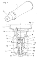
- a dispensing unit in particular for head-mounted use in a dispenser for dispensing a liquid or pasty medium, comprises a rigid, aeratable container 1 with a metering pump 5 arranged on its neck 2, which is covered by a protective cap 3 until use, such as Fig. 1 shows.
- the metering pump 5 comprises two essential parts 11, 16, of which the first part 11 arranged on the neck 2 of the container 1, in particular unsolvable glued or welded, when the container 1 and the metering pump 5 are made of a plastic.
- Such a dispensing unit is exchanged for a filled after emptying.
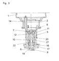
- the first part 11 of the metering pump 5 is formed as a hollow cylinder and in the connection region with the container, a suction opening is provided, which is associated with an intake valve in the form of a first one-way valve 6.
- the first valve body 7 provided in the first one-way valve is spherical and held loosely in a valve cage 12 comprising a plurality of webs with inwardly projecting end protrusions.
- the valve seat is cone-shaped. Due to gravity, therefore, the first one-way valve 6 in the in Fig. 2 shown rest position open.
- Other suitable intake valves are for example flap valves, umbrella valves or beak valves.
- the second part 16 of the metering pump 5 forms the piston and is slidably disposed in the hollow cylindrical first part 11 against a spring 21, so that the delivery chamber 20 of the metering pump can change.
- the intake opening in the first part 11 opposite a discharge opening is provided in the second part 16, which is associated with a dispensing valve in the form of a rectified, so outwardly opening second one-way valve 8.
- the second one-way valve 8 has a conically widening valve body 9 which has a shaft 10 extending axially into the delivery chamber 20. The shaft ends at a variable distance a, which is smaller than the stroke h of the metering pump to the first valve body 7.
- the shaft 10 has an annular shoulder, and a closing spring 22 is clamped between the annular shoulder and the inside of the valve seat in the second part 16 , In the in Fig. 2 shown rest position is therefore the second one-way valve 8 sealingly closed.
- the closing spring 22 determines the opening pressure of the metering pump. 5
- the delivery chamber 20 is reduced by raising the piston-forming second part 16.
- the device used for this purpose is not the subject of the invention, wherein in Fig. 2 only one provided in the upside-down use in a dispenser driving sleeve 25 is shown by dashed lines, which engages around the second one-way valve 8 on an outer actuating lug 17 on the second part 16 of the metering pump 5. Below the discharge opening can still, optionally changeable, disc-like jet regulator 18 od. Like. Be provided to control flow rate or atomization of the escaping medium.
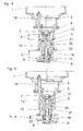
- the system of the shaft 10 to the first valve body 7 helps to eliminate or avoid malfunctions that may result from the fact that the second valve body 9 in particular also hangs under the action of the closing spring 22 in the discharge opening. These malfunctions are dependent on the type and consistency of the medium contained and simultaneous air inclusion in the delivery chamber 20, especially at the first use, just before consumption of the content, or prolonged disuse by gluing the second valve body 9 in the discharge opening.
- the lifting of the second piston-forming part 16 would in such a case empty the delivery chamber 20 only when the trapped air can be compressed to such an extent that the pressure is sufficient to release the second bonded valve body 9. If the proportion of air is too high, it would even be conceivable that the second valve body remains in its valve seat, and the metering pump is useless, since each stroke compresses only the air and each return stroke relaxes them, but not displaced.
- FIG. 4 An accident caused mainly by air entrapment of this kind is out Fig. 4 seen.
- the first valve body 7 is pressed into the valve seat, while the second valve body 9, which is additionally acted upon by the compression spring 22 has not moved down, so that the second one-way valve 8 also remains closed.
- the pressure in the delivery chamber 20 may increase sufficiently, and the second one-way valve 8 opens, whereupon further metering operations take place in the desired manner.
- a ventilation channel 14 is provided, which extends into the container 1 and is provided with a further one-way valve, in particular a duckbill valve.
- the spring 21 for the return of the second part 16 of the metering pump 5 can be omitted if the unspecified described actuator for the metering pump 5, from the in Fig. 2 the driving sleeve 25 is drawn by dashed lines, having a return spring or the like, and the driving sleeve 25, the actuating projection 17 forcibly leads in both directions.
Landscapes
- Containers And Packaging Bodies Having A Special Means To Remove Contents (AREA)
- Closures For Containers (AREA)
- Compressor (AREA)
- Massaging Devices (AREA)
- Beans For Foods Or Fodder (AREA)
Claims (6)
- Unité de distribution pour des agents liquides ou pâteux avec un récipient (1), sur le goulot duquel (2) une pompe de dosage (5) présentant deux parties (11, 16) est placée, une première partie cylindrique et creuse (11) de la pompe de dosage (5) étant contiguë au goulot (2) et présentant sur une ouverture d'aspiration une première soupape à une voie (6) avec un premier corps de soupape (7), une seconde partie (16) formant un piston de la pompe de dosage (5) étant pourvue d'une saillie d'actionnement (17) extérieure pour un levage (h) de la pompe de dosage (5), s'étendant de manière mobile dans la première partie (11) et présentant sur une ouverture de distribution s'alignant sur l'ouverture d'aspiration une seconde soupape à une voie (8) avec un second corps de soupape (9), de préférence sollicité par ressort, et les deux soupapes à une voie (6, 8) ouvrant dans la même direction et la distance (a) entre les deux corps de soupape (7, 9) étant variable, caractérisée en ce que le premier corps de soupape (7) agencé dans l'ouverture d'aspiration est réalisé comme une butée d'ouverture pour le second corps de soupape (9) agencé dans l'ouverture de distribution se trouvant en face.
- Unité de distribution selon la revendication 1, caractérisée en ce que le second corps de soupape (9) présente une tige (10) pénétrant axialement dans la pompe de dosage (5), dont l'extrémité libre est à distance (a) du premier corps de soupape (7).
- Unité de distribution selon la revendication 1 ou 2, caractérisée en ce que la seconde soupape à une voie présente un siège de soupape conique et un corps de soupape (9) en forme de cône.
- Unité de distribution selon l'une quelconque des revendications 1 à 3, caractérisée en ce que le premier corps de soupape (7) est réalisé de manière sphérique.
- Unité de distribution selon la revendication 4, caractérisée en ce que le premier corps de soupape (7) est maintenu lâche dans une cage de soupape (12) prévue dans la première partie (11) de la pompe de dosage (5) pour une utilisation inversée.
- Unité de distribution selon l'une quelconque des revendications 1 à 5, caractérisée en ce que le récipient (1) est incompressible et la première partie (11) présente un canal d'entrée d'air (14) équipé d'une soupape à une voie.
Priority Applications (3)
| Application Number | Priority Date | Filing Date | Title |
|---|---|---|---|
| SI201330114T SI2844397T1 (sl) | 2012-04-30 | 2013-04-26 | Razdeljevalna enota |
| PL13728922T PL2844397T3 (pl) | 2012-04-30 | 2013-04-26 | Zespół dozujący |
| HRP20160029TT HRP20160029T1 (hr) | 2012-04-30 | 2013-04-26 | Uređaj za izdavanje |
Applications Claiming Priority (2)
| Application Number | Priority Date | Filing Date | Title |
|---|---|---|---|
| ATA518/2012A AT511827B1 (de) | 2012-04-30 | 2012-04-30 | Abgabeeinheit für flüssige oder pastöse Medien |
| PCT/AT2013/000080 WO2013163666A2 (fr) | 2012-04-30 | 2013-04-26 | Unité de distribution pour substances liquides ou pâteuses |
Publications (2)
| Publication Number | Publication Date |
|---|---|
| EP2844397A2 EP2844397A2 (fr) | 2015-03-11 |
| EP2844397B1 true EP2844397B1 (fr) | 2015-10-21 |
Family
ID=47833616
Family Applications (1)
| Application Number | Title | Priority Date | Filing Date |
|---|---|---|---|
| EP13728922.9A Active EP2844397B1 (fr) | 2012-04-30 | 2013-04-26 | Unité de distribution |
Country Status (10)
| Country | Link |
|---|---|
| EP (1) | EP2844397B1 (fr) |
| AT (1) | AT511827B1 (fr) |
| ES (1) | ES2559266T3 (fr) |
| HR (1) | HRP20160029T1 (fr) |
| HU (1) | HUE028392T2 (fr) |
| PL (1) | PL2844397T3 (fr) |
| PT (1) | PT2844397E (fr) |
| RS (1) | RS54484B1 (fr) |
| SI (1) | SI2844397T1 (fr) |
| WO (1) | WO2013163666A2 (fr) |
Family Cites Families (9)
| Publication number | Priority date | Publication date | Assignee | Title |
|---|---|---|---|---|
| US4511069A (en) * | 1981-06-04 | 1985-04-16 | The Pharmasol Corporation | Dispensing system |
| GB8507868D0 (en) * | 1985-03-26 | 1985-05-01 | Salesprint Temple Group Ltd | Liquid dispenser |
| US4964544A (en) * | 1988-08-16 | 1990-10-23 | Bobrick Washroom Equipment, Inc. | Push up dispenser with capsule valve |
| US4949877A (en) * | 1989-05-11 | 1990-08-21 | Bobrick Washroom Equipment, Inc. | Fluid dispenser valve |
| US4993600A (en) * | 1989-10-10 | 1991-02-19 | James River Corporation | Liquid dispenser pump |
| US5975360A (en) * | 1991-05-20 | 1999-11-02 | Ophardt; Heiner | Capped piston pump |
| DE19713721C2 (de) * | 1997-04-03 | 2000-04-20 | Calmar Albert Gmbh | Spender |
| US6516976B2 (en) * | 2000-12-19 | 2003-02-11 | Kimberly-Clark Worldwide, Inc. | Dosing pump for liquid dispensers |
| PT2135681E (pt) * | 2008-06-20 | 2015-08-24 | Gojo Ind Inc | Bomba de espuma a dois tempos |
-
2012
- 2012-04-30 AT ATA518/2012A patent/AT511827B1/de not_active IP Right Cessation
-
2013
- 2013-04-26 EP EP13728922.9A patent/EP2844397B1/fr active Active
- 2013-04-26 SI SI201330114T patent/SI2844397T1/sl unknown
- 2013-04-26 RS RS20160007A patent/RS54484B1/sr unknown
- 2013-04-26 PT PT137289229T patent/PT2844397E/pt unknown
- 2013-04-26 PL PL13728922T patent/PL2844397T3/pl unknown
- 2013-04-26 ES ES13728922.9T patent/ES2559266T3/es active Active
- 2013-04-26 WO PCT/AT2013/000080 patent/WO2013163666A2/fr not_active Ceased
- 2013-04-26 HU HUE13728922A patent/HUE028392T2/en unknown
- 2013-04-26 HR HRP20160029TT patent/HRP20160029T1/hr unknown
Also Published As
| Publication number | Publication date |
|---|---|
| HRP20160029T1 (hr) | 2016-02-12 |
| ES2559266T3 (es) | 2016-02-11 |
| PL2844397T3 (pl) | 2016-04-29 |
| SI2844397T1 (sl) | 2016-02-29 |
| WO2013163666A2 (fr) | 2013-11-07 |
| EP2844397A2 (fr) | 2015-03-11 |
| AT511827B1 (de) | 2013-03-15 |
| RS54484B1 (sr) | 2016-06-30 |
| PT2844397E (pt) | 2016-01-28 |
| AT511827A4 (de) | 2013-03-15 |
| HUE028392T2 (en) | 2016-12-28 |
| WO2013163666A3 (fr) | 2013-12-27 |
Similar Documents
| Publication | Publication Date | Title |
|---|---|---|
| DE60035828T2 (de) | Austragsventileinrichtung für eine hebelbetätigte Sprühvorrichtung | |
| DE102009017459B4 (de) | Austragvorrichtung | |
| DE60107738T2 (de) | Portabler, selbstenergieerzeugender Druckzerstäuber | |
| DE60204988T2 (de) | Zerstäubungsvorrichtung mit lateraler betätigung | |
| DE69722716T2 (de) | Pumpenzerstäuber | |
| DE69110344T2 (de) | Sprüh- und Dosiervorrichtung. | |
| DE2513766A1 (de) | Pumpe fuer einen zerstaeuber | |
| DE69106111T2 (de) | Handbetätigte Pumpe für Fluide. | |
| DE3740823A1 (de) | Vorrichtung zur entnahme von fluessigkeiten aus einem behaelter und anordnung zur herstellung derselben | |
| EP2634112A1 (fr) | Récipient de sortie pouvant être rempli de nouveau | |
| WO2015106868A1 (fr) | Distributeur de liquide | |
| DE2717878A1 (de) | Vorrichtung zur dosierten abgabe von fluessigkeiten oder pasten | |
| DE102013218741B4 (de) | Spendersystem | |
| EP1332798A2 (fr) | Distributeur pour des produits fluides ou pâteux | |
| DE19827035A1 (de) | Applikator | |
| DE2640837A1 (de) | Manuell betaetigbare pumpe | |
| EP1904240B1 (fr) | Tete de decharge de fluide | |
| DE3624657A1 (de) | Abgabepumpe fuer ein stroemungsmittel aus einem behaelter | |
| DE102005043258A1 (de) | Vorrichtung zum dosierten Ausbringen eines Mediums | |
| DE1500617A1 (de) | Saug- und Druckpumpe zur Fluessigkeitsfoerderung,insbesondere fuer einen Fluessigkeitszerstaeuber | |
| EP2844397B1 (fr) | Unité de distribution | |
| DE69812621T2 (de) | In Öffnungs- sowie Schliessstellung abgedichter, handbetätigter Spender | |
| DE102004024471B3 (de) | Pumpe zur Entnahme von Flüssigkeit oder pastöser Masse, entsprechender Spendeapparat und entsprechendes Verfahren | |
| CH616382A5 (en) | Nebulising device for liquids | |
| EP2246122B1 (fr) | Dispositif de sortie pour milieux liquides ou pâteux |
Legal Events
| Date | Code | Title | Description |
|---|---|---|---|
| PUAI | Public reference made under article 153(3) epc to a published international application that has entered the european phase |
Free format text: ORIGINAL CODE: 0009012 |
|
| 17P | Request for examination filed |
Effective date: 20140929 |
|
| AK | Designated contracting states |
Kind code of ref document: A2 Designated state(s): AL AT BE BG CH CY CZ DE DK EE ES FI FR GB GR HR HU IE IS IT LI LT LU LV MC MK MT NL NO PL PT RO RS SE SI SK SM TR |
|
| AX | Request for extension of the european patent |
Extension state: BA ME |
|
| GRAP | Despatch of communication of intention to grant a patent |
Free format text: ORIGINAL CODE: EPIDOSNIGR1 |
|
| RAX | Requested extension states of the european patent have changed |
Extension state: BA Payment date: 20140929 |
|
| INTG | Intention to grant announced |
Effective date: 20150720 |
|
| GRAS | Grant fee paid |
Free format text: ORIGINAL CODE: EPIDOSNIGR3 |
|
| GRAA | (expected) grant |
Free format text: ORIGINAL CODE: 0009210 |
|
| AK | Designated contracting states |
Kind code of ref document: B1 Designated state(s): AL AT BE BG CH CY CZ DE DK EE ES FI FR GB GR HR HU IE IS IT LI LT LU LV MC MK MT NL NO PL PT RO RS SE SI SK SM TR |
|
| AX | Request for extension of the european patent |
Extension state: BA |
|
| REG | Reference to a national code |
Ref country code: GB Ref legal event code: FG4D Free format text: NOT ENGLISH |
|
| REG | Reference to a national code |
Ref country code: CH Ref legal event code: EP |
|
| REG | Reference to a national code |
Ref country code: AT Ref legal event code: REF Ref document number: 756239 Country of ref document: AT Kind code of ref document: T Effective date: 20151115 |
|
| REG | Reference to a national code |
Ref country code: IE Ref legal event code: FG4D Free format text: LANGUAGE OF EP DOCUMENT: GERMAN |
|
| REG | Reference to a national code |
Ref country code: DE Ref legal event code: R096 Ref document number: 502013001392 Country of ref document: DE |
|
| REG | Reference to a national code |
Ref country code: RO Ref legal event code: EPE |
|
| REG | Reference to a national code |
Ref country code: CH Ref legal event code: NV Representative=s name: ISLER AND PEDRAZZINI AG, CH |
|
| REG | Reference to a national code |
Ref country code: HR Ref legal event code: TUEP Ref document number: P20160029 Country of ref document: HR |
|
| REG | Reference to a national code |
Ref country code: PT Ref legal event code: SC4A Free format text: AVAILABILITY OF NATIONAL TRANSLATION Effective date: 20151229 |
|
| REG | Reference to a national code |
Ref country code: SE Ref legal event code: TRGR |
|
| REG | Reference to a national code |
Ref country code: ES Ref legal event code: FG2A Ref document number: 2559266 Country of ref document: ES Kind code of ref document: T3 Effective date: 20160211 |
|
| REG | Reference to a national code |
Ref country code: HR Ref legal event code: T1PR Ref document number: P20160029 Country of ref document: HR |
|
| REG | Reference to a national code |
Ref country code: LT Ref legal event code: MG4D |
|
| REG | Reference to a national code |
Ref country code: NL Ref legal event code: FP |
|
| PG25 | Lapsed in a contracting state [announced via postgrant information from national office to epo] |
Ref country code: NO Free format text: LAPSE BECAUSE OF FAILURE TO SUBMIT A TRANSLATION OF THE DESCRIPTION OR TO PAY THE FEE WITHIN THE PRESCRIBED TIME-LIMIT Effective date: 20160121 Ref country code: LT Free format text: LAPSE BECAUSE OF FAILURE TO SUBMIT A TRANSLATION OF THE DESCRIPTION OR TO PAY THE FEE WITHIN THE PRESCRIBED TIME-LIMIT Effective date: 20151021 Ref country code: IS Free format text: LAPSE BECAUSE OF FAILURE TO SUBMIT A TRANSLATION OF THE DESCRIPTION OR TO PAY THE FEE WITHIN THE PRESCRIBED TIME-LIMIT Effective date: 20160221 |
|
| PG25 | Lapsed in a contracting state [announced via postgrant information from national office to epo] |
Ref country code: GR Free format text: LAPSE BECAUSE OF FAILURE TO SUBMIT A TRANSLATION OF THE DESCRIPTION OR TO PAY THE FEE WITHIN THE PRESCRIBED TIME-LIMIT Effective date: 20160122 Ref country code: LV Free format text: LAPSE BECAUSE OF FAILURE TO SUBMIT A TRANSLATION OF THE DESCRIPTION OR TO PAY THE FEE WITHIN THE PRESCRIBED TIME-LIMIT Effective date: 20151021 Ref country code: FI Free format text: LAPSE BECAUSE OF FAILURE TO SUBMIT A TRANSLATION OF THE DESCRIPTION OR TO PAY THE FEE WITHIN THE PRESCRIBED TIME-LIMIT Effective date: 20151021 |
|
| REG | Reference to a national code |
Ref country code: SK Ref legal event code: T3 Ref document number: E 20278 Country of ref document: SK |
|
| REG | Reference to a national code |
Ref country code: DE Ref legal event code: R097 Ref document number: 502013001392 Country of ref document: DE |
|
| PLBE | No opposition filed within time limit |
Free format text: ORIGINAL CODE: 0009261 |
|
| STAA | Information on the status of an ep patent application or granted ep patent |
Free format text: STATUS: NO OPPOSITION FILED WITHIN TIME LIMIT |
|
| PG25 | Lapsed in a contracting state [announced via postgrant information from national office to epo] |
Ref country code: DK Free format text: LAPSE BECAUSE OF FAILURE TO SUBMIT A TRANSLATION OF THE DESCRIPTION OR TO PAY THE FEE WITHIN THE PRESCRIBED TIME-LIMIT Effective date: 20151021 Ref country code: BE Free format text: LAPSE BECAUSE OF NON-PAYMENT OF DUE FEES Effective date: 20160430 Ref country code: SM Free format text: LAPSE BECAUSE OF FAILURE TO SUBMIT A TRANSLATION OF THE DESCRIPTION OR TO PAY THE FEE WITHIN THE PRESCRIBED TIME-LIMIT Effective date: 20151021 Ref country code: EE Free format text: LAPSE BECAUSE OF FAILURE TO SUBMIT A TRANSLATION OF THE DESCRIPTION OR TO PAY THE FEE WITHIN THE PRESCRIBED TIME-LIMIT Effective date: 20151021 |
|
| PGFP | Annual fee paid to national office [announced via postgrant information from national office to epo] |
Ref country code: IT Payment date: 20160430 Year of fee payment: 4 |
|
| 26N | No opposition filed |
Effective date: 20160722 |
|
| REG | Reference to a national code |
Ref country code: HR Ref legal event code: PBON Ref document number: P20160029 Country of ref document: HR Effective date: 20160426 |
|
| REG | Reference to a national code |
Ref country code: DE Ref legal event code: R119 Ref document number: 502013001392 Country of ref document: DE |
|
| REG | Reference to a national code |
Ref country code: SE Ref legal event code: EUG |
|
| REG | Reference to a national code |
Ref country code: CH Ref legal event code: PL |
|
| REG | Reference to a national code |
Ref country code: NL Ref legal event code: MM Effective date: 20160501 |
|
| REG | Reference to a national code |
Ref country code: HU Ref legal event code: AG4A Ref document number: E028392 Country of ref document: HU |
|
| PG25 | Lapsed in a contracting state [announced via postgrant information from national office to epo] |
Ref country code: LU Free format text: LAPSE BECAUSE OF FAILURE TO SUBMIT A TRANSLATION OF THE DESCRIPTION OR TO PAY THE FEE WITHIN THE PRESCRIBED TIME-LIMIT Effective date: 20160426 |
|
| REG | Reference to a national code |
Ref country code: SK Ref legal event code: MM4A Ref document number: E 20278 Country of ref document: SK Effective date: 20160426 |
|
| REG | Reference to a national code |
Ref country code: IE Ref legal event code: MM4A |
|
| REG | Reference to a national code |
Ref country code: FR Ref legal event code: ST Effective date: 20161230 |
|
| PG25 | Lapsed in a contracting state [announced via postgrant information from national office to epo] |
Ref country code: FR Free format text: LAPSE BECAUSE OF NON-PAYMENT OF DUE FEES Effective date: 20160502 Ref country code: HU Free format text: LAPSE BECAUSE OF NON-PAYMENT OF DUE FEES Effective date: 20160427 Ref country code: LI Free format text: LAPSE BECAUSE OF NON-PAYMENT OF DUE FEES Effective date: 20160430 Ref country code: CH Free format text: LAPSE BECAUSE OF NON-PAYMENT OF DUE FEES Effective date: 20160430 Ref country code: SK Free format text: LAPSE BECAUSE OF NON-PAYMENT OF DUE FEES Effective date: 20160426 Ref country code: HR Free format text: LAPSE BECAUSE OF NON-PAYMENT OF DUE FEES Effective date: 20160426 Ref country code: CZ Free format text: LAPSE BECAUSE OF NON-PAYMENT OF DUE FEES Effective date: 20160426 Ref country code: RS Free format text: LAPSE BECAUSE OF NON-PAYMENT OF DUE FEES Effective date: 20161107 Ref country code: NL Free format text: LAPSE BECAUSE OF NON-PAYMENT OF DUE FEES Effective date: 20160501 Ref country code: DE Free format text: LAPSE BECAUSE OF NON-PAYMENT OF DUE FEES Effective date: 20161101 |
|
| REG | Reference to a national code |
Ref country code: SI Ref legal event code: KO00 Effective date: 20161227 |
|
| PG25 | Lapsed in a contracting state [announced via postgrant information from national office to epo] |
Ref country code: SE Free format text: LAPSE BECAUSE OF NON-PAYMENT OF DUE FEES Effective date: 20160427 Ref country code: SI Free format text: LAPSE BECAUSE OF NON-PAYMENT OF DUE FEES Effective date: 20160427 Ref country code: BG Free format text: LAPSE BECAUSE OF NON-PAYMENT OF DUE FEES Effective date: 20161031 |
|
| PG25 | Lapsed in a contracting state [announced via postgrant information from national office to epo] |
Ref country code: PT Free format text: LAPSE BECAUSE OF NON-PAYMENT OF DUE FEES Effective date: 20170126 Ref country code: IE Free format text: LAPSE BECAUSE OF NON-PAYMENT OF DUE FEES Effective date: 20160426 |
|
| PGFP | Annual fee paid to national office [announced via postgrant information from national office to epo] |
Ref country code: TR Payment date: 20170421 Year of fee payment: 5 |
|
| PG25 | Lapsed in a contracting state [announced via postgrant information from national office to epo] |
Ref country code: PL Free format text: LAPSE BECAUSE OF NON-PAYMENT OF DUE FEES Effective date: 20160426 |
|
| GBPC | Gb: european patent ceased through non-payment of renewal fee |
Effective date: 20170426 |
|
| PG25 | Lapsed in a contracting state [announced via postgrant information from national office to epo] |
Ref country code: GB Free format text: LAPSE BECAUSE OF NON-PAYMENT OF DUE FEES Effective date: 20170426 |
|
| PG25 | Lapsed in a contracting state [announced via postgrant information from national office to epo] |
Ref country code: IT Free format text: LAPSE BECAUSE OF NON-PAYMENT OF DUE FEES Effective date: 20170426 Ref country code: RO Free format text: LAPSE BECAUSE OF NON-PAYMENT OF DUE FEES Effective date: 20151021 Ref country code: ES Free format text: LAPSE BECAUSE OF NON-PAYMENT OF DUE FEES Effective date: 20160427 |
|
| REG | Reference to a national code |
Ref country code: ES Ref legal event code: FD2A Effective date: 20180625 |
|
| PG25 | Lapsed in a contracting state [announced via postgrant information from national office to epo] |
Ref country code: MK Free format text: LAPSE BECAUSE OF FAILURE TO SUBMIT A TRANSLATION OF THE DESCRIPTION OR TO PAY THE FEE WITHIN THE PRESCRIBED TIME-LIMIT Effective date: 20151021 Ref country code: MC Free format text: LAPSE BECAUSE OF FAILURE TO SUBMIT A TRANSLATION OF THE DESCRIPTION OR TO PAY THE FEE WITHIN THE PRESCRIBED TIME-LIMIT Effective date: 20151021 Ref country code: MT Free format text: LAPSE BECAUSE OF FAILURE TO SUBMIT A TRANSLATION OF THE DESCRIPTION OR TO PAY THE FEE WITHIN THE PRESCRIBED TIME-LIMIT Effective date: 20151021 Ref country code: CY Free format text: LAPSE BECAUSE OF FAILURE TO SUBMIT A TRANSLATION OF THE DESCRIPTION OR TO PAY THE FEE WITHIN THE PRESCRIBED TIME-LIMIT Effective date: 20151021 |
|
| PG25 | Lapsed in a contracting state [announced via postgrant information from national office to epo] |
Ref country code: AL Free format text: LAPSE BECAUSE OF FAILURE TO SUBMIT A TRANSLATION OF THE DESCRIPTION OR TO PAY THE FEE WITHIN THE PRESCRIBED TIME-LIMIT Effective date: 20151021 |
|
| PG25 | Lapsed in a contracting state [announced via postgrant information from national office to epo] |
Ref country code: TR Free format text: LAPSE BECAUSE OF NON-PAYMENT OF DUE FEES Effective date: 20180426 |
|
| PGFP | Annual fee paid to national office [announced via postgrant information from national office to epo] |
Ref country code: AT Payment date: 20250428 Year of fee payment: 13 |