EP2844397B1 - Abgabeeinheit - Google Patents
Abgabeeinheit Download PDFInfo
- Publication number
- EP2844397B1 EP2844397B1 EP13728922.9A EP13728922A EP2844397B1 EP 2844397 B1 EP2844397 B1 EP 2844397B1 EP 13728922 A EP13728922 A EP 13728922A EP 2844397 B1 EP2844397 B1 EP 2844397B1
- Authority
- EP
- European Patent Office
- Prior art keywords
- valve
- valve body
- metering pump
- delivery unit
- unit according
- Prior art date
- Legal status (The legal status is an assumption and is not a legal conclusion. Google has not performed a legal analysis and makes no representation as to the accuracy of the status listed.)
- Active
Links
Images
Classifications
-
- B—PERFORMING OPERATIONS; TRANSPORTING
- B05—SPRAYING OR ATOMISING IN GENERAL; APPLYING FLUENT MATERIALS TO SURFACES, IN GENERAL
- B05B—SPRAYING APPARATUS; ATOMISING APPARATUS; NOZZLES
- B05B11/00—Single-unit hand-held apparatus in which flow of contents is produced by the muscular force of the operator at the moment of use
- B05B11/0005—Components or details
- B05B11/0062—Outlet valves actuated by the pressure of the fluid to be sprayed
- B05B11/0064—Lift valves
-
- B—PERFORMING OPERATIONS; TRANSPORTING
- B05—SPRAYING OR ATOMISING IN GENERAL; APPLYING FLUENT MATERIALS TO SURFACES, IN GENERAL
- B05B—SPRAYING APPARATUS; ATOMISING APPARATUS; NOZZLES
- B05B11/00—Single-unit hand-held apparatus in which flow of contents is produced by the muscular force of the operator at the moment of use
- B05B11/0005—Components or details
- B05B11/0062—Outlet valves actuated by the pressure of the fluid to be sprayed
- B05B11/0072—A valve member forming part of an outlet opening
-
- B—PERFORMING OPERATIONS; TRANSPORTING
- B05—SPRAYING OR ATOMISING IN GENERAL; APPLYING FLUENT MATERIALS TO SURFACES, IN GENERAL
- B05B—SPRAYING APPARATUS; ATOMISING APPARATUS; NOZZLES
- B05B11/00—Single-unit hand-held apparatus in which flow of contents is produced by the muscular force of the operator at the moment of use
- B05B11/01—Single-unit hand-held apparatus in which flow of contents is produced by the muscular force of the operator at the moment of use characterised by the means producing the flow
- B05B11/10—Pump arrangements for transferring the contents from the container to a pump chamber by a sucking effect and forcing the contents out through the dispensing nozzle
- B05B11/1001—Piston pumps
-
- B—PERFORMING OPERATIONS; TRANSPORTING
- B05—SPRAYING OR ATOMISING IN GENERAL; APPLYING FLUENT MATERIALS TO SURFACES, IN GENERAL
- B05B—SPRAYING APPARATUS; ATOMISING APPARATUS; NOZZLES
- B05B11/00—Single-unit hand-held apparatus in which flow of contents is produced by the muscular force of the operator at the moment of use
- B05B11/01—Single-unit hand-held apparatus in which flow of contents is produced by the muscular force of the operator at the moment of use characterised by the means producing the flow
- B05B11/10—Pump arrangements for transferring the contents from the container to a pump chamber by a sucking effect and forcing the contents out through the dispensing nozzle
- B05B11/1038—Pressure accumulation pumps, i.e. pumps comprising a pressure accumulation chamber
- B05B11/104—Pressure accumulation pumps, i.e. pumps comprising a pressure accumulation chamber the outlet valve being opened by pressure after a defined accumulation stroke
-
- B—PERFORMING OPERATIONS; TRANSPORTING
- B05—SPRAYING OR ATOMISING IN GENERAL; APPLYING FLUENT MATERIALS TO SURFACES, IN GENERAL
- B05B—SPRAYING APPARATUS; ATOMISING APPARATUS; NOZZLES
- B05B11/00—Single-unit hand-held apparatus in which flow of contents is produced by the muscular force of the operator at the moment of use
- B05B11/0005—Components or details
- B05B11/0037—Containers
- B05B11/0039—Containers associated with means for compensating the pressure difference between the ambient pressure and the pressure inside the container, e.g. pressure relief means
- B05B11/0044—Containers associated with means for compensating the pressure difference between the ambient pressure and the pressure inside the container, e.g. pressure relief means compensating underpressure by ingress of atmospheric air into the container, i.e. with venting means
- B05B11/00442—Containers associated with means for compensating the pressure difference between the ambient pressure and the pressure inside the container, e.g. pressure relief means compensating underpressure by ingress of atmospheric air into the container, i.e. with venting means the means being actuated by the difference between the atmospheric pressure and the pressure inside the container
Definitions
- the invention relates to a dispensing unit for liquid or pasty media with a container, on the neck of a two-part metering pump is placed, wherein a hollow cylindrical first part of the metering pump connects to the neck and at a suction port a first one-way valve having a first valve body, said a piston-forming second part of the metering pump is provided with an outer actuating lug for a stroke of the metering pump, slidably extending in the first part, and at a suction opening aligned with the suction port, a second one-way valve having a preferably spring-loaded, second valve body, and wherein the two one-way valves open in the same direction, and the distance between the two valve bodies is variable.
- the first one-way valve will hereinafter also be referred to as a suction valve and the second one-way valve as a dispensing valve.
- a container with a metering pump for an unspecified liquid medium is known, wherein the container is in the delivery on the head.
- the two valve bodies are conical and arranged at the two ends of a spring-loaded rod, wherein in the rest position the second valve is closed at the discharge opening and the first valve is open at the suction opening, so that the pump chamber is filled with the medium.
- the first valve closes and the second opens, so that the portion contained in the pump chamber can flow out.
- the piston-forming second part then returns to the starting position, wherein the second valve closes and the first opens, so that the pump chamber fills again.
- the rigid connection of the two valve body leads to inaccuracies in the dosage, since the two valves are not optimally matched to each other, the flow properties of the medium play a role.
- the rigid connection has the advantage that, for example, in the case of air trapped in the pump chamber the Dispensing valve is reliably opened even if the resulting pressure in the pump chamber is not sufficient for this purpose.
- the invention has now taken on the task of creating an existing from the container and the associated metering pump dispensing unit, in which even in a fault inaccuracies in the dosage causing valve positions are avoided.
- This is achieved in that the first valve body arranged in the intake opening is designed as an opening stop for the second valve body arranged in the opposite discharge opening.
- the two valve bodies operate unaffected by a substantial part of the stroke of the pump from each other, and it comes before the end of the stroke only in case of failure, when the second valve body is stuck in the closed position, to a direct coupling between the two valve bodies, forcibly the dispensing valve opens. In the pump chamber trapped, compressed air can escape from the metering pump. This is especially for a first time operation of advantage.
- the coupling of the two valves also ensures that when a dried dispensing valve, as it may be the case for a longer standstill, the second valve body is mechanically opened.
- the closing force of the intake valve corresponds to the required opening force of the dispensing valve.
- the second valve body has an axially projecting into the metering shaft whose free end is at a distance from the first valve body.
- an abutment for the spring may be formed, which acts on the second valve body in the closed position, so that the dispensing valve is tight and the medium does not drip.
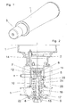
- a dispensing unit in particular for head-mounted use in a dispenser for dispensing a liquid or pasty medium, comprises a rigid, aeratable container 1 with a metering pump 5 arranged on its neck 2, which is covered by a protective cap 3 until use, such as Fig. 1 shows.
- the metering pump 5 comprises two essential parts 11, 16, of which the first part 11 arranged on the neck 2 of the container 1, in particular unsolvable glued or welded, when the container 1 and the metering pump 5 are made of a plastic.
- Such a dispensing unit is exchanged for a filled after emptying.
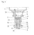
- the first part 11 of the metering pump 5 is formed as a hollow cylinder and in the connection region with the container, a suction opening is provided, which is associated with an intake valve in the form of a first one-way valve 6.
- the first valve body 7 provided in the first one-way valve is spherical and held loosely in a valve cage 12 comprising a plurality of webs with inwardly projecting end protrusions.
- the valve seat is cone-shaped. Due to gravity, therefore, the first one-way valve 6 in the in Fig. 2 shown rest position open.
- Other suitable intake valves are for example flap valves, umbrella valves or beak valves.
- the second part 16 of the metering pump 5 forms the piston and is slidably disposed in the hollow cylindrical first part 11 against a spring 21, so that the delivery chamber 20 of the metering pump can change.
- the intake opening in the first part 11 opposite a discharge opening is provided in the second part 16, which is associated with a dispensing valve in the form of a rectified, so outwardly opening second one-way valve 8.
- the second one-way valve 8 has a conically widening valve body 9 which has a shaft 10 extending axially into the delivery chamber 20. The shaft ends at a variable distance a, which is smaller than the stroke h of the metering pump to the first valve body 7.
- the shaft 10 has an annular shoulder, and a closing spring 22 is clamped between the annular shoulder and the inside of the valve seat in the second part 16 , In the in Fig. 2 shown rest position is therefore the second one-way valve 8 sealingly closed.
- the closing spring 22 determines the opening pressure of the metering pump. 5
- the delivery chamber 20 is reduced by raising the piston-forming second part 16.
- the device used for this purpose is not the subject of the invention, wherein in Fig. 2 only one provided in the upside-down use in a dispenser driving sleeve 25 is shown by dashed lines, which engages around the second one-way valve 8 on an outer actuating lug 17 on the second part 16 of the metering pump 5. Below the discharge opening can still, optionally changeable, disc-like jet regulator 18 od. Like. Be provided to control flow rate or atomization of the escaping medium.
- the system of the shaft 10 to the first valve body 7 helps to eliminate or avoid malfunctions that may result from the fact that the second valve body 9 in particular also hangs under the action of the closing spring 22 in the discharge opening. These malfunctions are dependent on the type and consistency of the medium contained and simultaneous air inclusion in the delivery chamber 20, especially at the first use, just before consumption of the content, or prolonged disuse by gluing the second valve body 9 in the discharge opening.
- the lifting of the second piston-forming part 16 would in such a case empty the delivery chamber 20 only when the trapped air can be compressed to such an extent that the pressure is sufficient to release the second bonded valve body 9. If the proportion of air is too high, it would even be conceivable that the second valve body remains in its valve seat, and the metering pump is useless, since each stroke compresses only the air and each return stroke relaxes them, but not displaced.
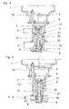
- FIG. 4 An accident caused mainly by air entrapment of this kind is out Fig. 4 seen.
- the first valve body 7 is pressed into the valve seat, while the second valve body 9, which is additionally acted upon by the compression spring 22 has not moved down, so that the second one-way valve 8 also remains closed.
- the pressure in the delivery chamber 20 may increase sufficiently, and the second one-way valve 8 opens, whereupon further metering operations take place in the desired manner.
- a ventilation channel 14 is provided, which extends into the container 1 and is provided with a further one-way valve, in particular a duckbill valve.
- the spring 21 for the return of the second part 16 of the metering pump 5 can be omitted if the unspecified described actuator for the metering pump 5, from the in Fig. 2 the driving sleeve 25 is drawn by dashed lines, having a return spring or the like, and the driving sleeve 25, the actuating projection 17 forcibly leads in both directions.
Landscapes
- Containers And Packaging Bodies Having A Special Means To Remove Contents (AREA)
- Closures For Containers (AREA)
- Compressor (AREA)
- Massaging Devices (AREA)
- Beans For Foods Or Fodder (AREA)
Description
- Die Erfindung betrifft eine Abgabeeinheit für flüssige oder pastöse Medien mit einem Behälter, auf dessen Hals eine zwei Teile aufweisende Dosierpumpe aufgesetzt ist, wobei ein hohlzylindrischer erster Teil der Dosierpumpe an den Hals anschließt und an einer Ansaugöffnung ein erstes Einwegventil mit einem ersten Ventilkörper aufweist, wobei ein kolbenbildender zweiter Teil der Dosierpumpe mit einem äußeren Betätigungsansatz für einen Hub der Dosierpumpe versehen ist, sich verschiebbar im ersten Teil erstreckt, und an einer mit der Ansaugöffnung fluchtenden Abgabeöffnung ein zweites Einwegventil mit einem vorzugsweise federbeaufschlagten, zweiten Ventilkörper aufweist, und wobei die beiden Einwegventile in die gleiche Richtung öffnen, und der Abstand zwischen den beiden Ventilkörpern variabel ist. Das erste Einwegventil wird nachstehend auch als Ansaugventil und das zweite Einwegventil als Abgabeventil bezeichnet.
- Siehe auch
WO 82/04203 - Aus der
FR 10 64 626 - Unter der Wirkung der Rückstellfeder kehrt der kolbenbildende zweite Teil dann in die Ausgangsstellung zurück, wobei das zweite Ventil schließt und das erste öffnet, sodass sich die Pumpenkammer wieder füllt.
- Die starre Verbindung der beiden Ventilkörper führt zu Ungenauigkeiten in der Dosierung, da die beiden Ventile nicht optimal aufeinander abstimmbar sind, wobei die Fließeigenschaften des Mediums eine Rolle spielen. Die starre Verbindung hat aber den Vorteil, dass beispielsweise bei Lufteinschluss in der Pumpenkammer das Abgabeventil auch dann verlässlich geöffnet wird, wenn der in der Pumpenkammer entstehende Druck hiefür nicht ausreicht.
- Die Erfindung hat sich nun die Aufgabe gestellt, eine aus dem Behälter und der damit verbundenen Dosierpumpe bestehende Abgabeeinheit zu schaffen, bei der auch in einem Störungsfall Ungenauigkeiten in der Dosierung verursachende Ventilstellungen vermieden sind. Dies wird dadurch erreicht, dass der in der Ansaugöffnung angeordnete erste Ventilkörper als Öffnungsanschlag für den in der gegenüber liegenden Abgabeöffnung angeordneten zweiten Ventilkörper ausgebildet ist.
- Auf diese Weise arbeiten die beiden Ventilkörper über einen wesentlichen Teil des Hubs der Pumpe voneinander unbeeinflusst, und es kommt vor Ende des Hubs nur im Störungsfall, wenn der zweite Ventilkörper in Schließstellung festsitzt, zu einer direkten Koppelung zwischen den beiden Ventilkörpern, die das Abgabeventil zwangweise öffnet. In der Pumpenkammer eingeschlossene, komprimierte Luft kann dadurch aus der Dosierpumpe austreten. Dies ist gerade bei einer erstmaligen Betätigung von Vorteil. Die Kopplung der beiden Ventile stellt auch sicher, dass bei einem eingetrockneten Abgabeventil, wie es bei einem längeren Stillstand der Fall sein kann, der zweite Ventilkörper mechanisch geöffnet wird. Die Schließkraft des Ansaugventils entspricht dabei der benötigten Öffnungskraft des Abgabeventils.
- Bevorzugt ist weiters vorgesehen, dass der zweite Ventilkörper einen axial in die Dosierpumpe ragenden Schaft aufweist, dessen freies Ende im Abstand zum ersten Ventilkörper ist.
- Am Schaft kann ein Widerlager für die Feder ausgebildet sein, die den zweiten Ventilkörper in Schließstellung beaufschlagt, sodass das Abgabeventil dicht ist und das Medium nicht nachtropft.
- Weitere Einzelheiten und Vorteile der vorliegenden Erfindung werden anhand der Figurenbeschreibung unter Bezugnahme auf die in den Zeichnungen dargestellten Ausführungsbeispiele im Folgenden näher erläutert. Darin zeigen:
- Fig. 1
- eine Schrägansicht einer erfindungsgemäßen Abgabeeinheit mit abgedeckter Dosierpumpe,
- Fig. 2
- einen Längsschnitt durch die Dosierpumpe in Ruhestellung,
- Fig. 3
- einen Längsschnitt durch die Dosierpumpe nach Abgabe einer Portion des Mediums,
- Fig. 4
- einen Längsschnitt durch die Dosierpumpe in einer störungsbedingten Schließstellung beider Ventilkörper, und
- Fig. 5
- einen Längsschnitt durch die Dosierpumpe gemäß
Fig. 4 vor Zwangsöffnung des Abgabeventils. - Eine Abgabeeinheit, insbesondere zur kopfstehenden Verwendung in einem Spender für die Abgabe eines flüssigen oder pastösen Mediums umfasst einen steifen, belüftbaren Behälter 1 mit einer auf dessen Hals 2 angeordneten Dosierpumpe 5, die bis zur Verwendung von einer Schutzkappe 3 abgedeckt ist, wie
Fig. 1 zeigt. Die Dosierpumpe 5 umfasst zwei wesentliche Teile 11, 16, von denen der erste Teil 11 am Hals 2 des Behälters 1 angeordnet, insbesondere unlösbar verklebt oder verschweißt ist, wenn der Behälter 1 und die Dosierpumpe 5 aus einem Kunststoff gefertigt sind. Eine derartige Abgabeeinheit wird nach Entleerung gegen eine gefüllte getauscht. Es wäre aber auch denkbar, die Dosierpumpe 5 lösbar am Behälter 1 anzubringen, sodass die Abgabeeinheit wieder befüllt und verwendet werden kann. - Der erste Teil 11 der Dosierpumpe 5 ist hohlzylindrisch ausgebildet und im Verbindungsbereich mit dem Behälter ist eine Ansaugöffnung vorgesehen, der ein Ansaugventil in Form eines ersten Einwegventils 6 zugeordnet ist. Für die in den Figuren gezeigte kopfstehende Anordnung ist der im ersten Einwegventil vorgesehene erste Ventilkörper 7 kugelig ausgebildet und in einem mehrere Stege mit nach innen vorstehenden Endvorsprüngen umfassenden Ventilkäfig 12 lose gehalten. Der Ventilsitz ist kegelförmig. Aufgrund der Schwerkraft ist daher das erste Einwegventil 6 in der in
Fig. 2 gezeigten Ruhestellung offen. Andere geeignete Ansaugventile sind beispielsweise Klappenventile, Schirmventile oder Schnabelventile. - Der zweite Teil 16 der Dosierpumpe 5 bildet deren Kolben und ist im hohlzylindrischen ersten Teil 11 gegen eine Feder 21 verschiebbar angeordnet, sodass der Förderraum 20 der Dosierpumpe sich verändern kann. Der Ansaugöffnung im ersten Teil 11 gegenüberliegend ist im zweiten Teil 16 eine Abgabeöffnung vorgesehen, der ein Abgabeventil in Form eines gleichgerichteten, also nach außen öffnenden zweiten Einwegventils 8 zugeordnet ist. Das zweite Einwegventil 8 hat einen sich konisch erweiternden Ventilkörper 9, der einen sich axial in den Förderraum 20 erstreckenden Schaft 10 aufweist. Der Schaft endet in einem variablen Abstand a, der kleiner als der Hub h der Dosierpumpe ist, zum ersten Ventilkörper 7. Der Schaft 10 weist eine Ringschulter auf, und eine Schließfeder 22 ist zwischen der Ringschulter und der Innenseite des Ventilsitzes im zweiten Teil 16 eingespannt. In der in
Fig. 2 gezeigten Ruhestellung ist daher das zweite Einwegventil 8 dichtend geschlossen. Die Schließfeder 22 bestimmt den Öffnungsdruck der Dosierpumpe 5. - Der Förderraum 20 wird durch Anheben des kolbenbildenden zweiten Teiles 16 verkleinert. Die hiefür verwendete Einrichtung ist nicht Gegenstand der Erfindung, wobei in
Fig. 2 nur eine in der kopfstehenden Verwendung in einem Spender vorgesehene Mitnahmehülse 25 strichliert gezeichnet ist, die rund um das zweite Einwegventil 8 an einem äußeren Betätigungsansatz 17 am zweiten Teil 16 der Dosierpumpe 5 angreift. Unterhalb der Abgabeöffnung kann noch ein, gegebenenfalls wechselbarer, scheibenartiger Strahlregler 18 od. dgl. vorgesehen sein, um Fließgeschwindigkeit bzw. Zerstäubung des austretenden Mediums zu kontrollieren. - Wird die Mitnahmehülse 25 aus der Stellung nach
Fig. 2 angehoben, so wird im Förderraum 20 eingeschlossenes Medium über das zweite Einwegventil 8 durch die Abgabeöffnung ausgedrückt, da das erste Einwegventil 6 den Weg in den Behälter 1 sperrt. Am Ende des Hubs liegt der Schaft 10 des zweiten Ventilkörpers 9 am ersten Ventilkörper 7 an. Wird die Dosierpumpe 5 in der komprimierten Stellung, die inFig. 3 gezeigt ist, wieder freigegeben, so vergrößert sich unter der Wirkung der Feder 21 der Förderraum 20, wobei zu Beginn des Rückhubs aufgrund der Anlage des Schafts 10 am Ventilkörper 7 durch das noch offene zweite Einwegventil 8 ein im Ventilbereich hängender Rest des Mediums in den Förderraum 20 rückgesaugt wird, sodass ein Nachtropfen vermieden wird. Nach diesem kurzen Augenblick entfernt sich bei fortschreitendem Rückhub der Schaft 10 vom ersten Ventilkörper 7, sodass sich einerseits das zweite Einwegventil 8 schließen und andererseits das erste Einwegventil 6 öffnen kann. Nunmehr wird Medium aus dem Behälter 1 angesaugt, bis der Rückhub abgeschlossen ist und die Ruhestellung nachFig. 2 wieder erreicht ist. - Die Anlage des Schaftes 10 an den ersten Ventilkörper 7 hilft Funktionsstörungen zu beheben oder zu vermeiden, die sich daraus ergeben können, dass der zweite Ventilkörper 9 insbesondere auch unter der Wirkung der Schließfeder 22 in der Abgabeöffnung hängen bleibt. Diese Funktionsstörungen sind abhängig von der Art und Konsistenz des enthaltenen Mediums und gleichzeitigem Lufteinschluss im Förderraum 20, vor allem bei der Erstverwendung, knapp vor Aufbrauch des Inhalts, oder bei längerem Nichtgebrauch durch Verkleben des zweiten Ventilkörpers 9 in der Abgabeöffnung. Das Anheben des zweiten kolbenbildenden Teiles 16 würde in einem derartigen Fall den Förderraum 20 erst dann entleeren, wenn die eingeschlossene Luft so weit komprimiert werden kann, dass der Druck ausreicht, um den zweiten verklebten Ventilkörper 9 zu lösen. Ist der Luftanteil zu hoch, so wäre es sogar denkbar, dass der zweite Ventilkörper in seinem Ventilsitz verbleibt, und die Dosierpumpe unbrauchbar ist, da jeder Hub nur die Luft komprimiert und jeder Rückhub sie wieder entspannt, aber nicht verdrängt.
- Ein vor allem durch Lufteinschluss bedingter Störfall dieser Art ist aus
Fig. 4 ersichtlich. Zu Beginn des Hubes schließt das erste Einwegventil 6, und der erste Ventilkörper 7 wird in den Ventilsitz gedrückt, während der zweite Ventilkörper 9, der ja zusätzlich von der Druckfeder 22 beaufschlagt ist, sich nicht nach unten bewegt hat, sodass das zweite Einwegventil 8 ebenfalls geschlossen bleibt. Beim weiteren Anheben kann sich der Druck im Förderraum 20 ausreichend erhöhen, und das zweite Einwegventil 8 öffnet, worauf weitere Dosiervorgänge in der gewünschten Weise ablaufen. Reicht dies aber nicht aus, so stößt der Schaft 10 des zweiten Ventilkörpers 9 nach etwa zwei Drittel des Hubs h - der Ventilkörper 9 liegt ja höher und näher zum ersten Einwegventil 6, als wenn er geöffnet hätte - an den ersten Ventilkörper 7. Dieser Moment ist inFig. 5 dargestellt. Der verbleibende Resthub h-a überführt den Ventilkörper 9 zwangsläufig in die offene Stellung gemäßFig. 3 , sodass die Dosierpumpe 5 wieder funktionsfähig wird und bleibt, und bei der nächsten Betätigung eine vollständige Portion abgegeben wird. - Damit in einen Behälter 1, der nicht durch äußeren Luftdruck zusammengedrückt werden soll, Luft einströmen kann, wenn das Medium in den Förderraum 20 abgesaugt wird, ist in dem am Hals 2 fixierten Bereich des ersten Teiles 11 der Dosierpumpe 5 ein Belüftungskanal 14 vorgesehen, der sich in den Behälter 1 erstreckt und mit einem weiteren Einwegventil, insbesondere einem Entenschnabelventil versehen ist.
- Die Feder 21 für die Rückstellung des zweiten Teiles 16 der Dosierpumpe 5 kann entfallen, wenn die nicht näher beschriebene Betätigungseinrichtung für die Dosierpumpe 5, von der in
Fig. 2 die Mitnahmehülse 25 strichliert gezeichnet ist, eine Rückstellfeder oder dergleichen aufweist, und die Mitnahmehülse 25 den Betätigungsansatz 17 in beide Richtungen zwangführt.
Claims (6)
- Abgabeeinheit für flüssige oder pastöse Medien mit einem Behälter (1), auf dessen Hals (2) eine zwei Teile (11, 16) aufweisende Dosierpumpe (5) aufgesetzt ist, wobei ein hohlzylindrischer erster Teil (11) der Dosierpumpe (5) an den Hals (2) anschließt und an einer Ansaugöffnung ein erstes Einwegventil (6) mit einem ersten Ventilkörper (7) aufweist, wobei ein kolbenbildender zweiter Teil (16) der Dosierpumpe (5) mit einem äußeren Betätigungsansatz (17) für einen Hub (h) der Dosierpumpe (5) versehen ist, sich verschiebbar im ersten Teil (11) erstreckt, und an einer mit der Ansaugöffnung fluchtenden Abgabeöffnung ein zweites Einwegventil (8) mit einem vorzugsweise federbeaufschlagten, zweiten Ventilkörper (9) aufweist, und wobei die beiden Einwegventile (6, 8) in die gleiche Richtung öffnen, und der Abstand (a) zwischen den beiden Ventilkörpern (7, 9) variabel ist, dadurch gekennzeichnet, dass der in der Ansaugöffnung angeordnete erste Ventilkörper (7) als Öffnungsanschlag für den in der gegenüber liegenden Abgabeöffnung angeordneten zweiten Ventilkörper (9) ausgebildet ist.
- Abgabeeinheit nach Anspruch 1, dadurch gekennzeichnet, dass der zweite Ventilkörper (9) einen axial in die Dosierpumpe (5) ragenden Schaft (10) aufweist, dessen freies Ende im Abstand (a) zum ersten Ventilkörper (7) ist.
- Abgabeeinheit nach Anspruch 1 oder 2, dadurch gekennzeichnet, dass das zweite Einwegventil einen konischen Ventilsitz und einen kegeligen Ventilkörper (9) aufweist.
- Abgabeeinheit nach einem der Ansprüche 1 bis 3, dadurch gekennzeichnet, dass der erste Ventilkörper (7) kugelig ausgebildet ist.
- Abgabeeinheit nach Anspruch 4, dadurch gekennzeichnet, dass für eine kopfstehende Verwendung der erste Ventilkörper (7) in einem im ersten Teil (11) der Dosierpumpe (5) vorgesehenen Ventilkäfig (12) lose gehalten ist.
- Abgabeeinheit nach einem der Ansprüche 1 bis 5, dadurch gekennzeichnet, dass der Behälter (1) nichtkompressibel ist und der erste Teil (11) einen mit einem Einwegventil bestückten Lufteinlasskanal (14) aufweist.
Priority Applications (3)
| Application Number | Priority Date | Filing Date | Title |
|---|---|---|---|
| PL13728922T PL2844397T3 (pl) | 2012-04-30 | 2013-04-26 | Zespół dozujący |
| SI201330114T SI2844397T1 (sl) | 2012-04-30 | 2013-04-26 | Razdeljevalna enota |
| HRP20160029TT HRP20160029T1 (hr) | 2012-04-30 | 2013-04-26 | Uređaj za izdavanje |
Applications Claiming Priority (2)
| Application Number | Priority Date | Filing Date | Title |
|---|---|---|---|
| ATA518/2012A AT511827B1 (de) | 2012-04-30 | 2012-04-30 | Abgabeeinheit für flüssige oder pastöse Medien |
| PCT/AT2013/000080 WO2013163666A2 (de) | 2012-04-30 | 2013-04-26 | Abgabeeinheit für flüssige oder pastöse medien |
Publications (2)
| Publication Number | Publication Date |
|---|---|
| EP2844397A2 EP2844397A2 (de) | 2015-03-11 |
| EP2844397B1 true EP2844397B1 (de) | 2015-10-21 |
Family
ID=47833616
Family Applications (1)
| Application Number | Title | Priority Date | Filing Date |
|---|---|---|---|
| EP13728922.9A Active EP2844397B1 (de) | 2012-04-30 | 2013-04-26 | Abgabeeinheit |
Country Status (10)
| Country | Link |
|---|---|
| EP (1) | EP2844397B1 (de) |
| AT (1) | AT511827B1 (de) |
| ES (1) | ES2559266T3 (de) |
| HR (1) | HRP20160029T1 (de) |
| HU (1) | HUE028392T2 (de) |
| PL (1) | PL2844397T3 (de) |
| PT (1) | PT2844397E (de) |
| RS (1) | RS54484B1 (de) |
| SI (1) | SI2844397T1 (de) |
| WO (1) | WO2013163666A2 (de) |
Family Cites Families (9)
| Publication number | Priority date | Publication date | Assignee | Title |
|---|---|---|---|---|
| JPS58500845A (ja) * | 1981-06-04 | 1983-05-26 | デラウェア・ケミカルス・コーポレーション | ポンプ |
| GB8507868D0 (en) * | 1985-03-26 | 1985-05-01 | Salesprint Temple Group Ltd | Liquid dispenser |
| US4964544A (en) * | 1988-08-16 | 1990-10-23 | Bobrick Washroom Equipment, Inc. | Push up dispenser with capsule valve |
| US4949877A (en) * | 1989-05-11 | 1990-08-21 | Bobrick Washroom Equipment, Inc. | Fluid dispenser valve |
| US4993600A (en) * | 1989-10-10 | 1991-02-19 | James River Corporation | Liquid dispenser pump |
| US5975360A (en) * | 1991-05-20 | 1999-11-02 | Ophardt; Heiner | Capped piston pump |
| DE19713721C2 (de) * | 1997-04-03 | 2000-04-20 | Calmar Albert Gmbh | Spender |
| US6516976B2 (en) * | 2000-12-19 | 2003-02-11 | Kimberly-Clark Worldwide, Inc. | Dosing pump for liquid dispensers |
| PT2135681E (pt) * | 2008-06-20 | 2015-08-24 | Gojo Ind Inc | Bomba de espuma a dois tempos |
-
2012
- 2012-04-30 AT ATA518/2012A patent/AT511827B1/de not_active IP Right Cessation
-
2013
- 2013-04-26 RS RS20160007A patent/RS54484B1/sr unknown
- 2013-04-26 PL PL13728922T patent/PL2844397T3/pl unknown
- 2013-04-26 WO PCT/AT2013/000080 patent/WO2013163666A2/de not_active Ceased
- 2013-04-26 EP EP13728922.9A patent/EP2844397B1/de active Active
- 2013-04-26 ES ES13728922.9T patent/ES2559266T3/es active Active
- 2013-04-26 HR HRP20160029TT patent/HRP20160029T1/hr unknown
- 2013-04-26 PT PT137289229T patent/PT2844397E/pt unknown
- 2013-04-26 SI SI201330114T patent/SI2844397T1/sl unknown
- 2013-04-26 HU HUE13728922A patent/HUE028392T2/en unknown
Also Published As
| Publication number | Publication date |
|---|---|
| WO2013163666A3 (de) | 2013-12-27 |
| HUE028392T2 (en) | 2016-12-28 |
| ES2559266T3 (es) | 2016-02-11 |
| RS54484B1 (sr) | 2016-06-30 |
| AT511827A4 (de) | 2013-03-15 |
| WO2013163666A2 (de) | 2013-11-07 |
| PL2844397T3 (pl) | 2016-04-29 |
| SI2844397T1 (sl) | 2016-02-29 |
| HRP20160029T1 (hr) | 2016-02-12 |
| AT511827B1 (de) | 2013-03-15 |
| PT2844397E (pt) | 2016-01-28 |
| EP2844397A2 (de) | 2015-03-11 |
Similar Documents
| Publication | Publication Date | Title |
|---|---|---|
| DE60035828T2 (de) | Austragsventileinrichtung für eine hebelbetätigte Sprühvorrichtung | |
| DE102009017459B4 (de) | Austragvorrichtung | |
| DE60107738T2 (de) | Portabler, selbstenergieerzeugender Druckzerstäuber | |
| DE60204988T2 (de) | Zerstäubungsvorrichtung mit lateraler betätigung | |
| DE69722716T2 (de) | Pumpenzerstäuber | |
| DE69110344T2 (de) | Sprüh- und Dosiervorrichtung. | |
| DE2513766A1 (de) | Pumpe fuer einen zerstaeuber | |
| DE69106111T2 (de) | Handbetätigte Pumpe für Fluide. | |
| DE3740823A1 (de) | Vorrichtung zur entnahme von fluessigkeiten aus einem behaelter und anordnung zur herstellung derselben | |
| EP2634112A1 (de) | Wiederbefüllbarer Ausgabebehälter | |
| WO2015106868A1 (de) | Spender für flüssigkeiten | |
| DE102013218741B4 (de) | Spendersystem | |
| EP1332798A2 (de) | Spender für flüssige oder pastöse Produkte | |
| DE19827035A1 (de) | Applikator | |
| DE2640837A1 (de) | Manuell betaetigbare pumpe | |
| EP1904240B1 (de) | Fluidaustragkopf | |
| DE3624657A1 (de) | Abgabepumpe fuer ein stroemungsmittel aus einem behaelter | |
| DE102005043258A1 (de) | Vorrichtung zum dosierten Ausbringen eines Mediums | |
| DE1500617A1 (de) | Saug- und Druckpumpe zur Fluessigkeitsfoerderung,insbesondere fuer einen Fluessigkeitszerstaeuber | |
| EP2844397B1 (de) | Abgabeeinheit | |
| DE69812621T2 (de) | In Öffnungs- sowie Schliessstellung abgedichter, handbetätigter Spender | |
| DE102004024471B3 (de) | Pumpe zur Entnahme von Flüssigkeit oder pastöser Masse, entsprechender Spendeapparat und entsprechendes Verfahren | |
| CH616382A5 (en) | Nebulising device for liquids | |
| EP2246122B1 (de) | Austragvorrichtung für flüssige oder pastöse Medien | |
| CH684850A5 (de) | Dosiereinrichtung für Flüssigkeiten. |
Legal Events
| Date | Code | Title | Description |
|---|---|---|---|
| PUAI | Public reference made under article 153(3) epc to a published international application that has entered the european phase |
Free format text: ORIGINAL CODE: 0009012 |
|
| 17P | Request for examination filed |
Effective date: 20140929 |
|
| AK | Designated contracting states |
Kind code of ref document: A2 Designated state(s): AL AT BE BG CH CY CZ DE DK EE ES FI FR GB GR HR HU IE IS IT LI LT LU LV MC MK MT NL NO PL PT RO RS SE SI SK SM TR |
|
| AX | Request for extension of the european patent |
Extension state: BA ME |
|
| GRAP | Despatch of communication of intention to grant a patent |
Free format text: ORIGINAL CODE: EPIDOSNIGR1 |
|
| RAX | Requested extension states of the european patent have changed |
Extension state: BA Payment date: 20140929 |
|
| INTG | Intention to grant announced |
Effective date: 20150720 |
|
| GRAS | Grant fee paid |
Free format text: ORIGINAL CODE: EPIDOSNIGR3 |
|
| GRAA | (expected) grant |
Free format text: ORIGINAL CODE: 0009210 |
|
| AK | Designated contracting states |
Kind code of ref document: B1 Designated state(s): AL AT BE BG CH CY CZ DE DK EE ES FI FR GB GR HR HU IE IS IT LI LT LU LV MC MK MT NL NO PL PT RO RS SE SI SK SM TR |
|
| AX | Request for extension of the european patent |
Extension state: BA |
|
| REG | Reference to a national code |
Ref country code: GB Ref legal event code: FG4D Free format text: NOT ENGLISH |
|
| REG | Reference to a national code |
Ref country code: CH Ref legal event code: EP |
|
| REG | Reference to a national code |
Ref country code: AT Ref legal event code: REF Ref document number: 756239 Country of ref document: AT Kind code of ref document: T Effective date: 20151115 |
|
| REG | Reference to a national code |
Ref country code: IE Ref legal event code: FG4D Free format text: LANGUAGE OF EP DOCUMENT: GERMAN |
|
| REG | Reference to a national code |
Ref country code: DE Ref legal event code: R096 Ref document number: 502013001392 Country of ref document: DE |
|
| REG | Reference to a national code |
Ref country code: RO Ref legal event code: EPE |
|
| REG | Reference to a national code |
Ref country code: CH Ref legal event code: NV Representative=s name: ISLER AND PEDRAZZINI AG, CH |
|
| REG | Reference to a national code |
Ref country code: HR Ref legal event code: TUEP Ref document number: P20160029 Country of ref document: HR |
|
| REG | Reference to a national code |
Ref country code: PT Ref legal event code: SC4A Free format text: AVAILABILITY OF NATIONAL TRANSLATION Effective date: 20151229 |
|
| REG | Reference to a national code |
Ref country code: SE Ref legal event code: TRGR |
|
| REG | Reference to a national code |
Ref country code: ES Ref legal event code: FG2A Ref document number: 2559266 Country of ref document: ES Kind code of ref document: T3 Effective date: 20160211 |
|
| REG | Reference to a national code |
Ref country code: HR Ref legal event code: T1PR Ref document number: P20160029 Country of ref document: HR |
|
| REG | Reference to a national code |
Ref country code: LT Ref legal event code: MG4D |
|
| REG | Reference to a national code |
Ref country code: NL Ref legal event code: FP |
|
| PG25 | Lapsed in a contracting state [announced via postgrant information from national office to epo] |
Ref country code: NO Free format text: LAPSE BECAUSE OF FAILURE TO SUBMIT A TRANSLATION OF THE DESCRIPTION OR TO PAY THE FEE WITHIN THE PRESCRIBED TIME-LIMIT Effective date: 20160121 Ref country code: LT Free format text: LAPSE BECAUSE OF FAILURE TO SUBMIT A TRANSLATION OF THE DESCRIPTION OR TO PAY THE FEE WITHIN THE PRESCRIBED TIME-LIMIT Effective date: 20151021 Ref country code: IS Free format text: LAPSE BECAUSE OF FAILURE TO SUBMIT A TRANSLATION OF THE DESCRIPTION OR TO PAY THE FEE WITHIN THE PRESCRIBED TIME-LIMIT Effective date: 20160221 |
|
| PG25 | Lapsed in a contracting state [announced via postgrant information from national office to epo] |
Ref country code: GR Free format text: LAPSE BECAUSE OF FAILURE TO SUBMIT A TRANSLATION OF THE DESCRIPTION OR TO PAY THE FEE WITHIN THE PRESCRIBED TIME-LIMIT Effective date: 20160122 Ref country code: LV Free format text: LAPSE BECAUSE OF FAILURE TO SUBMIT A TRANSLATION OF THE DESCRIPTION OR TO PAY THE FEE WITHIN THE PRESCRIBED TIME-LIMIT Effective date: 20151021 Ref country code: FI Free format text: LAPSE BECAUSE OF FAILURE TO SUBMIT A TRANSLATION OF THE DESCRIPTION OR TO PAY THE FEE WITHIN THE PRESCRIBED TIME-LIMIT Effective date: 20151021 |
|
| REG | Reference to a national code |
Ref country code: SK Ref legal event code: T3 Ref document number: E 20278 Country of ref document: SK |
|
| REG | Reference to a national code |
Ref country code: DE Ref legal event code: R097 Ref document number: 502013001392 Country of ref document: DE |
|
| PLBE | No opposition filed within time limit |
Free format text: ORIGINAL CODE: 0009261 |
|
| STAA | Information on the status of an ep patent application or granted ep patent |
Free format text: STATUS: NO OPPOSITION FILED WITHIN TIME LIMIT |
|
| PG25 | Lapsed in a contracting state [announced via postgrant information from national office to epo] |
Ref country code: DK Free format text: LAPSE BECAUSE OF FAILURE TO SUBMIT A TRANSLATION OF THE DESCRIPTION OR TO PAY THE FEE WITHIN THE PRESCRIBED TIME-LIMIT Effective date: 20151021 Ref country code: BE Free format text: LAPSE BECAUSE OF NON-PAYMENT OF DUE FEES Effective date: 20160430 Ref country code: SM Free format text: LAPSE BECAUSE OF FAILURE TO SUBMIT A TRANSLATION OF THE DESCRIPTION OR TO PAY THE FEE WITHIN THE PRESCRIBED TIME-LIMIT Effective date: 20151021 Ref country code: EE Free format text: LAPSE BECAUSE OF FAILURE TO SUBMIT A TRANSLATION OF THE DESCRIPTION OR TO PAY THE FEE WITHIN THE PRESCRIBED TIME-LIMIT Effective date: 20151021 |
|
| PGFP | Annual fee paid to national office [announced via postgrant information from national office to epo] |
Ref country code: IT Payment date: 20160430 Year of fee payment: 4 |
|
| 26N | No opposition filed |
Effective date: 20160722 |
|
| REG | Reference to a national code |
Ref country code: HR Ref legal event code: PBON Ref document number: P20160029 Country of ref document: HR Effective date: 20160426 |
|
| REG | Reference to a national code |
Ref country code: DE Ref legal event code: R119 Ref document number: 502013001392 Country of ref document: DE |
|
| REG | Reference to a national code |
Ref country code: SE Ref legal event code: EUG |
|
| REG | Reference to a national code |
Ref country code: CH Ref legal event code: PL |
|
| REG | Reference to a national code |
Ref country code: NL Ref legal event code: MM Effective date: 20160501 |
|
| REG | Reference to a national code |
Ref country code: HU Ref legal event code: AG4A Ref document number: E028392 Country of ref document: HU |
|
| PG25 | Lapsed in a contracting state [announced via postgrant information from national office to epo] |
Ref country code: LU Free format text: LAPSE BECAUSE OF FAILURE TO SUBMIT A TRANSLATION OF THE DESCRIPTION OR TO PAY THE FEE WITHIN THE PRESCRIBED TIME-LIMIT Effective date: 20160426 |
|
| REG | Reference to a national code |
Ref country code: SK Ref legal event code: MM4A Ref document number: E 20278 Country of ref document: SK Effective date: 20160426 |
|
| REG | Reference to a national code |
Ref country code: IE Ref legal event code: MM4A |
|
| REG | Reference to a national code |
Ref country code: FR Ref legal event code: ST Effective date: 20161230 |
|
| PG25 | Lapsed in a contracting state [announced via postgrant information from national office to epo] |
Ref country code: FR Free format text: LAPSE BECAUSE OF NON-PAYMENT OF DUE FEES Effective date: 20160502 Ref country code: HU Free format text: LAPSE BECAUSE OF NON-PAYMENT OF DUE FEES Effective date: 20160427 Ref country code: LI Free format text: LAPSE BECAUSE OF NON-PAYMENT OF DUE FEES Effective date: 20160430 Ref country code: CH Free format text: LAPSE BECAUSE OF NON-PAYMENT OF DUE FEES Effective date: 20160430 Ref country code: SK Free format text: LAPSE BECAUSE OF NON-PAYMENT OF DUE FEES Effective date: 20160426 Ref country code: HR Free format text: LAPSE BECAUSE OF NON-PAYMENT OF DUE FEES Effective date: 20160426 Ref country code: CZ Free format text: LAPSE BECAUSE OF NON-PAYMENT OF DUE FEES Effective date: 20160426 Ref country code: RS Free format text: LAPSE BECAUSE OF NON-PAYMENT OF DUE FEES Effective date: 20161107 Ref country code: NL Free format text: LAPSE BECAUSE OF NON-PAYMENT OF DUE FEES Effective date: 20160501 Ref country code: DE Free format text: LAPSE BECAUSE OF NON-PAYMENT OF DUE FEES Effective date: 20161101 |
|
| REG | Reference to a national code |
Ref country code: SI Ref legal event code: KO00 Effective date: 20161227 |
|
| PG25 | Lapsed in a contracting state [announced via postgrant information from national office to epo] |
Ref country code: SE Free format text: LAPSE BECAUSE OF NON-PAYMENT OF DUE FEES Effective date: 20160427 Ref country code: SI Free format text: LAPSE BECAUSE OF NON-PAYMENT OF DUE FEES Effective date: 20160427 Ref country code: BG Free format text: LAPSE BECAUSE OF NON-PAYMENT OF DUE FEES Effective date: 20161031 |
|
| PG25 | Lapsed in a contracting state [announced via postgrant information from national office to epo] |
Ref country code: PT Free format text: LAPSE BECAUSE OF NON-PAYMENT OF DUE FEES Effective date: 20170126 Ref country code: IE Free format text: LAPSE BECAUSE OF NON-PAYMENT OF DUE FEES Effective date: 20160426 |
|
| PGFP | Annual fee paid to national office [announced via postgrant information from national office to epo] |
Ref country code: TR Payment date: 20170421 Year of fee payment: 5 |
|
| PG25 | Lapsed in a contracting state [announced via postgrant information from national office to epo] |
Ref country code: PL Free format text: LAPSE BECAUSE OF NON-PAYMENT OF DUE FEES Effective date: 20160426 |
|
| GBPC | Gb: european patent ceased through non-payment of renewal fee |
Effective date: 20170426 |
|
| PG25 | Lapsed in a contracting state [announced via postgrant information from national office to epo] |
Ref country code: GB Free format text: LAPSE BECAUSE OF NON-PAYMENT OF DUE FEES Effective date: 20170426 |
|
| PG25 | Lapsed in a contracting state [announced via postgrant information from national office to epo] |
Ref country code: IT Free format text: LAPSE BECAUSE OF NON-PAYMENT OF DUE FEES Effective date: 20170426 Ref country code: RO Free format text: LAPSE BECAUSE OF NON-PAYMENT OF DUE FEES Effective date: 20151021 Ref country code: ES Free format text: LAPSE BECAUSE OF NON-PAYMENT OF DUE FEES Effective date: 20160427 |
|
| REG | Reference to a national code |
Ref country code: ES Ref legal event code: FD2A Effective date: 20180625 |
|
| PG25 | Lapsed in a contracting state [announced via postgrant information from national office to epo] |
Ref country code: MK Free format text: LAPSE BECAUSE OF FAILURE TO SUBMIT A TRANSLATION OF THE DESCRIPTION OR TO PAY THE FEE WITHIN THE PRESCRIBED TIME-LIMIT Effective date: 20151021 Ref country code: MC Free format text: LAPSE BECAUSE OF FAILURE TO SUBMIT A TRANSLATION OF THE DESCRIPTION OR TO PAY THE FEE WITHIN THE PRESCRIBED TIME-LIMIT Effective date: 20151021 Ref country code: MT Free format text: LAPSE BECAUSE OF FAILURE TO SUBMIT A TRANSLATION OF THE DESCRIPTION OR TO PAY THE FEE WITHIN THE PRESCRIBED TIME-LIMIT Effective date: 20151021 Ref country code: CY Free format text: LAPSE BECAUSE OF FAILURE TO SUBMIT A TRANSLATION OF THE DESCRIPTION OR TO PAY THE FEE WITHIN THE PRESCRIBED TIME-LIMIT Effective date: 20151021 |
|
| PG25 | Lapsed in a contracting state [announced via postgrant information from national office to epo] |
Ref country code: AL Free format text: LAPSE BECAUSE OF FAILURE TO SUBMIT A TRANSLATION OF THE DESCRIPTION OR TO PAY THE FEE WITHIN THE PRESCRIBED TIME-LIMIT Effective date: 20151021 |
|
| PG25 | Lapsed in a contracting state [announced via postgrant information from national office to epo] |
Ref country code: TR Free format text: LAPSE BECAUSE OF NON-PAYMENT OF DUE FEES Effective date: 20180426 |
|
| PGFP | Annual fee paid to national office [announced via postgrant information from national office to epo] |
Ref country code: AT Payment date: 20250428 Year of fee payment: 13 |