EP2843775A1 - Connecteur en u pour signaux RF intégrés avec circuit de polarisation - Google Patents
Connecteur en u pour signaux RF intégrés avec circuit de polarisation Download PDFInfo
- Publication number
- EP2843775A1 EP2843775A1 EP14161949.4A EP14161949A EP2843775A1 EP 2843775 A1 EP2843775 A1 EP 2843775A1 EP 14161949 A EP14161949 A EP 14161949A EP 2843775 A1 EP2843775 A1 EP 2843775A1
- Authority
- EP
- European Patent Office
- Prior art keywords
- connector
- inner conductor
- link
- link connector
- antenna
- Prior art date
- Legal status (The legal status is an assumption and is not a legal conclusion. Google has not performed a legal analysis and makes no representation as to the accuracy of the status listed.)
- Withdrawn
Links
Images


Classifications
-
- H—ELECTRICITY
- H01—ELECTRIC ELEMENTS
- H01R—ELECTRICALLY-CONDUCTIVE CONNECTIONS; STRUCTURAL ASSOCIATIONS OF A PLURALITY OF MUTUALLY-INSULATED ELECTRICAL CONNECTING ELEMENTS; COUPLING DEVICES; CURRENT COLLECTORS
- H01R24/00—Two-part coupling devices, or either of their cooperating parts, characterised by their overall structure
- H01R24/38—Two-part coupling devices, or either of their cooperating parts, characterised by their overall structure having concentrically or coaxially arranged contacts
- H01R24/40—Two-part coupling devices, or either of their cooperating parts, characterised by their overall structure having concentrically or coaxially arranged contacts specially adapted for high frequency
- H01R24/42—Two-part coupling devices, or either of their cooperating parts, characterised by their overall structure having concentrically or coaxially arranged contacts specially adapted for high frequency comprising impedance matching means or electrical components, e.g. filters or switches
-
- H—ELECTRICITY
- H01—ELECTRIC ELEMENTS
- H01R—ELECTRICALLY-CONDUCTIVE CONNECTIONS; STRUCTURAL ASSOCIATIONS OF A PLURALITY OF MUTUALLY-INSULATED ELECTRICAL CONNECTING ELEMENTS; COUPLING DEVICES; CURRENT COLLECTORS
- H01R2103/00—Two poles
-
- H—ELECTRICITY
- H01—ELECTRIC ELEMENTS
- H01R—ELECTRICALLY-CONDUCTIVE CONNECTIONS; STRUCTURAL ASSOCIATIONS OF A PLURALITY OF MUTUALLY-INSULATED ELECTRICAL CONNECTING ELEMENTS; COUPLING DEVICES; CURRENT COLLECTORS
- H01R2201/00—Connectors or connections adapted for particular applications
- H01R2201/02—Connectors or connections adapted for particular applications for antennas
-
- H—ELECTRICITY
- H01—ELECTRIC ELEMENTS
- H01R—ELECTRICALLY-CONDUCTIVE CONNECTIONS; STRUCTURAL ASSOCIATIONS OF A PLURALITY OF MUTUALLY-INSULATED ELECTRICAL CONNECTING ELEMENTS; COUPLING DEVICES; CURRENT COLLECTORS
- H01R2201/00—Connectors or connections adapted for particular applications
- H01R2201/20—Connectors or connections adapted for particular applications for testing or measuring purposes
Definitions
- the invention relates to a connector for RF signals, preferably to a U-link connector for use in a broadcast patch panel.
- the antenna cables are subject to long-term degradation or failure due to electrical, mechanical and environmental stress.
- a monitoring of the antenna cables and/or antennas is desired.
- a standard method for monitoring the antenna cables is to disconnect the transmitters during maintenance and to measure the electrical properties of the cables.
- a disconnection of a transmitter may be done by a U-link connector as disclosed in DE 37 06 989 A1 or US 6,139,369 , which may be attached to a patch panel. This method does not allow for a continuous monitoring of the cables and requires a shutdown of the station.
- the problem to be solved by the invention is to provide a means and a method for testing and/or monitoring antenna cables in radio transmission and communication systems. There should be a simple and cost effective way of refurbishing existing systems. Furthermore it is preferred, if a continuous monitoring even curing operation of the system it possible
- a first embodiment relates to a U-link connector for use in a broadcast patch panel, the connector having the function of a test adapter and comprising electrical or electronic components for coupling a test device to the antenna cable to be monitored.
- the U-link connector comprises a filter circuit for coupling DC signals to the antenna cable.
- the connector may have the function of a bias tee.
- Such a U- link connector can easily be attached to a broadcast patch panel, which usually is provided between the transmitter(s) and the receiver(s) of a radio station.
- simply existing old U- link connectors are replaced by the new U- link connector with integrated electrical or electronic components. This allows for a very simple and inexpensive refurbishment of existing stations. It is no more necessary to alter existing cables or waveguides.
- a U- link connector has a first RF connector and a second RF connector. Both RF connectors preferably are coaxial connectors and further preferably are of the same type. Most preferably, they are male connectors.
- the RF connectors are connected by a RF line within the U- link connector, preferably a coaxial line.
- This coaxial line may have an outer conductor, which may be formed by or within the housing of the U- link connector.
- the outer conductor of the U-link connector connects the outer conductors of the RF connectors.
- the U- link connector comprises a coaxial line, it may also comprise a strip line or any other line suitable for transmission of RF signals.
- the inner conductor comprises and/or forms a series capacitor for coupling RF or high frequency signals between the first RF connector and the second RF connector, while blocking DC or low-frequency signals.
- the capacitor may be a gap between conductor parts, a stack of plates or any other capacitive element.
- the inner conductor comprises a first inner conductor section and a second inner conductor section, which preferably are flat metal plates. They are arranged, in close proximity parallel with each other to form the coupling capacitor.
- a dielectric material is provided between the first inner conductor section and the second inner conductor section. This material may be PTFE or Polyimide or any other dielectric material.
- the inner conductor sections may have bent portions for increasing coupling and mechanical stability.
- the inductor connected between the first RF connector and a first test connector.
- the first test connector may be used for connecting a test and/or measuring and/or monitoring device.
- the purpose of the inductor is to allow coupling of DC or low frequency signals between the test connector and the first RF connector for blocking RF or high-frequency signals.
- the embodiments shown herein have to provide at least a low VSWR and a low attenuation between the first RF connector and the second RF connector. Furthermore, they should be able to transfer high RF power levels as these are generated by the transmitters.
- first and second RF connectors relate to first and second RF connectors. It is obvious, that the connectors may be exchanged, if necessary. Furthermore, there are no limitations on the specific type of RF connectors.
- inventions shown herein may also be applied to antennas, which are only used for receiving signals and therefore handle lower power levels.
- a further embodiment relates to a patch panel in a radio station comprising at least one U- link connector as disclosed herein.
- a method for coupling a DC or low frequency signals to an antenna cable and/or antenna comprises the steps of connecting a U- link connector as described above to a patch panel being connected to the antenna cable and coupling the DC or low-frequency signals via the U- link connector to the antenna.
- the method includes coupling RF signals from the second RF connector to the first RF connector, most preferably by means of a serious capacitor.
- a method for refurbishing of radio stations or equipment of radio stations includes the step of replacing an existing U- link connector by a U- link connector as disclosed herein to provide access for test equipment to an antenna and its cable.
- the method further comprises the step of connecting a test device to a first test connector of the U- link connector.
- testing of the antenna and its cable may be done by the test device.
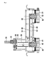
- a housing 10 holds a first RF connector 40 and a second RF connector 50.
- the housing further forms an outer conductor holding an inner conductor 60 for guiding a RF signal between the second RF connector 50 and the first RF connector 40, preferably in a TEM mode. It is preferred, if a transmitter (not shown here) is connected to the second RF connector 50, while an antenna connected by an antenna cable (not shown here) is connected to the first RF connector 40.
- the first RF connector 40 has an outer conductor 41 and an inner conductor 42.
- the second RF connector 50 has an outer conductor 51 and the inner conductor 52.
- the inner conductor 60 forms a coupling capacitor 20 for coupling RF and high-frequency signal as well as blocking DC and low-frequency signals between the RF connectors.
- a first inner conductor section 61 connected to the inner conductor 42 of the first RF connector 40 and a second inner conductor section 62 connected to the inner conductor 52 of the second RF connector 50.
- the first inner conductor section 61 and the second inner conductor section 62 are metal plates, which are arranged, in close proximity parallel with each other to form a coupling capacitor 20.
- a dielectric material 63 is arranged between the first inner conductor section 61 and the second inner conductor section 62. This material may be PTFE or Polyimide.
- the coupling capacitor 20 may also be a separate component connected between the first inner conductor section 61 and the second inner conductor section 62. It is obvious, that the inner conductor 60 is split to prevent a short circuit of the capacitor.
- An inductor 30 is arranged in close proximity to the first RF connector 40. Although the inductor may be anywhere else, this results in a compact mechanical design with good RF characteristics.
- the inductance is wound to a coil being supported by a coil core 35.
- Its first coil connecting line 31 is connected to a first test connector 33.
- a second coil connecting line 32 at the opposite end of the coil is connected to the first connector inner conductor 42 and to the first inner conductor section 61 of inner conductor 60.
- FIG. 2 shows a sectional view at the portion of the U- link connector close to the first RF connector 40.
- a load connector 34 can be seen which preferably is terminated by a load.
- a specific connector (not shown here) may be used.
- Figure 3 shows a top view.
- the short-circuit connector 35 can be seen on top of coil housing 36.
- Section line A-A relates to the sectional view of figure 1
- section line B-B relates to the sectional view of figure 2 .
- FIG 4 a schematic circuit diagram is shown.
- a transmitter 71 is connected to second RF connector 50.
- An antenna together with its cable 70 is connected to first RF connector 40.
- a test device 72 is connected to first test connector 33.
- the devices 71 and 70 are connected by coaxial lines.
- the ground symbol relates to the housing 10.
Landscapes
- Details Of Connecting Devices For Male And Female Coupling (AREA)
- Monitoring And Testing Of Transmission In General (AREA)
- Transceivers (AREA)
- Coupling Device And Connection With Printed Circuit (AREA)
Priority Applications (3)
| Application Number | Priority Date | Filing Date | Title |
|---|---|---|---|
| EP14161949.4A EP2843775A1 (fr) | 2013-08-28 | 2014-03-27 | Connecteur en u pour signaux RF intégrés avec circuit de polarisation |
| ES14182135T ES2702632T3 (es) | 2013-08-28 | 2014-08-25 | Conector de enlace en U para señales de RF con circuito de polarización integrado |
| EP14182135.5A EP2843776B1 (fr) | 2013-08-28 | 2014-08-25 | Connecteur en U pour signaux RF intégrés avec circuit de polarisation |
Applications Claiming Priority (2)
| Application Number | Priority Date | Filing Date | Title |
|---|---|---|---|
| EP13182039 | 2013-08-28 | ||
| EP14161949.4A EP2843775A1 (fr) | 2013-08-28 | 2014-03-27 | Connecteur en u pour signaux RF intégrés avec circuit de polarisation |
Publications (1)
| Publication Number | Publication Date |
|---|---|
| EP2843775A1 true EP2843775A1 (fr) | 2015-03-04 |
Family
ID=49036474
Family Applications (2)
| Application Number | Title | Priority Date | Filing Date |
|---|---|---|---|
| EP14161949.4A Withdrawn EP2843775A1 (fr) | 2013-08-28 | 2014-03-27 | Connecteur en u pour signaux RF intégrés avec circuit de polarisation |
| EP14182135.5A Active EP2843776B1 (fr) | 2013-08-28 | 2014-08-25 | Connecteur en U pour signaux RF intégrés avec circuit de polarisation |
Family Applications After (1)
| Application Number | Title | Priority Date | Filing Date |
|---|---|---|---|
| EP14182135.5A Active EP2843776B1 (fr) | 2013-08-28 | 2014-08-25 | Connecteur en U pour signaux RF intégrés avec circuit de polarisation |
Country Status (2)
| Country | Link |
|---|---|
| EP (2) | EP2843775A1 (fr) |
| ES (1) | ES2702632T3 (fr) |
Citations (8)
| Publication number | Priority date | Publication date | Assignee | Title |
|---|---|---|---|---|
| US4107631A (en) | 1974-07-11 | 1978-08-15 | Spinner Gmbh Elektrotechnische Fabrik | Protection of high-power coaxial cables |
| DE3706989A1 (de) | 1987-03-04 | 1988-09-15 | Spinner Georg | Sender/antennen-umsteckfeld |
| EP0936699A2 (fr) * | 1998-02-12 | 1999-08-18 | General Instrument Corporation | Système de dérivation pour une prise de télévision par câble |
| US6139369A (en) | 1997-07-31 | 2000-10-31 | Telefonaktiebolaget Lm Ericsson | Coaxial connector for equipment in a transmission network |
| WO2004013989A1 (fr) * | 2002-08-03 | 2004-02-12 | Kmw Inc. | Appareil a polarisation t et conducteur central pour cet appareil |
| US7094104B1 (en) * | 2005-05-04 | 2006-08-22 | Andrew Corporation | In-line coaxial circuit assembly |
| WO2009086498A1 (fr) * | 2007-12-29 | 2009-07-09 | Andrew Llc | Ensemble coupleur directionnel monté sur une carte de circuit imprimé |
| EP2088652A2 (fr) * | 2008-01-31 | 2009-08-12 | Andrew LLC | Arrêt de dérivation bas |
Family Cites Families (2)
| Publication number | Priority date | Publication date | Assignee | Title |
|---|---|---|---|---|
| US4749968A (en) * | 1985-12-13 | 1988-06-07 | Adc Telecommunications, Inc. | Jack device |
| US6887093B1 (en) * | 2003-11-20 | 2005-05-03 | Spx Corporation | Patch panel latching and holding mechanism apparatus and method |
-
2014
- 2014-03-27 EP EP14161949.4A patent/EP2843775A1/fr not_active Withdrawn
- 2014-08-25 ES ES14182135T patent/ES2702632T3/es active Active
- 2014-08-25 EP EP14182135.5A patent/EP2843776B1/fr active Active
Patent Citations (8)
| Publication number | Priority date | Publication date | Assignee | Title |
|---|---|---|---|---|
| US4107631A (en) | 1974-07-11 | 1978-08-15 | Spinner Gmbh Elektrotechnische Fabrik | Protection of high-power coaxial cables |
| DE3706989A1 (de) | 1987-03-04 | 1988-09-15 | Spinner Georg | Sender/antennen-umsteckfeld |
| US6139369A (en) | 1997-07-31 | 2000-10-31 | Telefonaktiebolaget Lm Ericsson | Coaxial connector for equipment in a transmission network |
| EP0936699A2 (fr) * | 1998-02-12 | 1999-08-18 | General Instrument Corporation | Système de dérivation pour une prise de télévision par câble |
| WO2004013989A1 (fr) * | 2002-08-03 | 2004-02-12 | Kmw Inc. | Appareil a polarisation t et conducteur central pour cet appareil |
| US7094104B1 (en) * | 2005-05-04 | 2006-08-22 | Andrew Corporation | In-line coaxial circuit assembly |
| WO2009086498A1 (fr) * | 2007-12-29 | 2009-07-09 | Andrew Llc | Ensemble coupleur directionnel monté sur une carte de circuit imprimé |
| EP2088652A2 (fr) * | 2008-01-31 | 2009-08-12 | Andrew LLC | Arrêt de dérivation bas |
Also Published As
| Publication number | Publication date |
|---|---|
| EP2843776B1 (fr) | 2018-09-26 |
| EP2843776A2 (fr) | 2015-03-04 |
| EP2843776A3 (fr) | 2015-03-18 |
| ES2702632T3 (es) | 2019-03-04 |
Similar Documents
| Publication | Publication Date | Title |
|---|---|---|
| US8116714B2 (en) | Use of powerlines for transmission of high frequency signals | |
| JP4599302B2 (ja) | 方向性結合器 | |
| US20110074388A1 (en) | Embedded coupler device and method of use thereoff | |
| US20110080057A1 (en) | Power harvesting device and method of use thereof | |
| US6283771B1 (en) | Grounding techniques to improve the performance of RF coaxial lightning protector | |
| EP2605416B1 (fr) | Dispositif de couplage de haute tension | |
| JP6179969B2 (ja) | 無線カバレッジが可能であるか否か判定するシステム | |
| EP2843776B1 (fr) | Connecteur en U pour signaux RF intégrés avec circuit de polarisation | |
| EP3407419A1 (fr) | Ensemble antenne, ensemble de circuit non blindé et ensemble d'unité rayonnante | |
| KR101276232B1 (ko) | 무선 통신장비용 커플러 | |
| US7312694B2 (en) | Capacitive couplers and methods for communicating data over an electrical power delivery system | |
| US11056842B2 (en) | Jumper cable with capacitive power enhancement and/or overvoltage protection | |
| KR102558018B1 (ko) | 후면 연결부를 구비하는 캐비티-백 커플러 | |
| US10193335B2 (en) | Radio frequency surge protector with matched piston-cylinder cavity shape | |
| JP2015115853A (ja) | 無線通信装置システム、無線通信装置、差込側コネクタおよび無線特性測定方法 | |
| CN102545930B (zh) | 无线通信装置 | |
| NZ598327B (en) | Antenna protection device and system | |
| US20140204489A1 (en) | Surge Discharge Point for Devices | |
| US20100039738A1 (en) | Inductive coupler for power line communications, having a member that provides an intended path for a flashover to discharge to ground | |
| CN109961122A (zh) | 便携式电子装置、射频装置及其信号传输构件 | |
| WO2011109023A1 (fr) | Utilisation de lignes électriques pour la transmission de signaux haute fréquence | |
| CN101083355A (zh) | 天线结构 |
Legal Events
| Date | Code | Title | Description |
|---|---|---|---|
| 17P | Request for examination filed |
Effective date: 20140327 |
|
| AK | Designated contracting states |
Kind code of ref document: A1 Designated state(s): AL AT BE BG CH CY CZ DE DK EE ES FI FR GB GR HR HU IE IS IT LI LT LU LV MC MK MT NL NO PL PT RO RS SE SI SK SM TR |
|
| AX | Request for extension of the european patent |
Extension state: BA ME |
|
| PUAI | Public reference made under article 153(3) epc to a published international application that has entered the european phase |
Free format text: ORIGINAL CODE: 0009012 |
|
| STAA | Information on the status of an ep patent application or granted ep patent |
Free format text: STATUS: THE APPLICATION IS DEEMED TO BE WITHDRAWN |
|
| 18D | Application deemed to be withdrawn |
Effective date: 20150905 |