EP2843743A1 - Unités d'électrodes à membrane pour piles à combustible à haute température avec une stabilité améliorée - Google Patents
Unités d'électrodes à membrane pour piles à combustible à haute température avec une stabilité améliorée Download PDFInfo
- Publication number
- EP2843743A1 EP2843743A1 EP14180738.8A EP14180738A EP2843743A1 EP 2843743 A1 EP2843743 A1 EP 2843743A1 EP 14180738 A EP14180738 A EP 14180738A EP 2843743 A1 EP2843743 A1 EP 2843743A1
- Authority
- EP
- European Patent Office
- Prior art keywords
- polymer
- membrane
- acid
- aromatic
- membrane electrode
- Prior art date
- Legal status (The legal status is an assumption and is not a legal conclusion. Google has not performed a legal analysis and makes no representation as to the accuracy of the status listed.)
- Granted
Links
- 239000012528 membrane Substances 0.000 title claims abstract description 166
- 239000000446 fuel Substances 0.000 title abstract description 25
- 229920000642 polymer Polymers 0.000 claims description 125
- 125000003118 aryl group Chemical group 0.000 claims description 54
- -1 1,2-phenylene, 1,3-phenylene, 1,4-phenylene Chemical group 0.000 claims description 53
- 239000002253 acid Substances 0.000 claims description 52
- 239000007789 gas Substances 0.000 claims description 45
- 239000005518 polymer electrolyte Substances 0.000 claims description 43
- 239000003054 catalyst Substances 0.000 claims description 40
- 229920002492 poly(sulfone) Polymers 0.000 claims description 40
- 238000009792 diffusion process Methods 0.000 claims description 32
- 125000001072 heteroaryl group Chemical group 0.000 claims description 29
- 125000002950 monocyclic group Chemical group 0.000 claims description 24
- 125000003367 polycyclic group Chemical group 0.000 claims description 24
- 150000007513 acids Chemical class 0.000 claims description 16
- 229910052739 hydrogen Inorganic materials 0.000 claims description 16
- 239000001257 hydrogen Substances 0.000 claims description 13
- 125000000524 functional group Chemical group 0.000 claims description 12
- 230000007774 longterm Effects 0.000 claims description 10
- SMWDFEZZVXVKRB-UHFFFAOYSA-N Quinoline Chemical compound N1=CC=CC2=CC=CC=C21 SMWDFEZZVXVKRB-UHFFFAOYSA-N 0.000 claims description 9
- QVGXLLKOCUKJST-UHFFFAOYSA-N atomic oxygen Chemical compound [O] QVGXLLKOCUKJST-UHFFFAOYSA-N 0.000 claims description 9
- 229910052799 carbon Inorganic materials 0.000 claims description 9
- 229910052760 oxygen Inorganic materials 0.000 claims description 9
- 239000001301 oxygen Substances 0.000 claims description 9
- 239000010970 precious metal Substances 0.000 claims description 9
- UFWIBTONFRDIAS-UHFFFAOYSA-N Naphthalene Chemical compound C1=CC=CC2=CC=CC=C21 UFWIBTONFRDIAS-UHFFFAOYSA-N 0.000 claims description 8
- JUJWROOIHBZHMG-UHFFFAOYSA-N Pyridine Chemical compound C1=CC=NC=C1 JUJWROOIHBZHMG-UHFFFAOYSA-N 0.000 claims description 8
- 125000000217 alkyl group Chemical group 0.000 claims description 8
- 229910052757 nitrogen Inorganic materials 0.000 claims description 8
- YNPNZTXNASCQKK-UHFFFAOYSA-N phenanthrene Chemical compound C1=CC=C2C3=CC=CC=C3C=CC2=C1 YNPNZTXNASCQKK-UHFFFAOYSA-N 0.000 claims description 8
- 125000004433 nitrogen atom Chemical group N* 0.000 claims description 6
- 125000004435 hydrogen atom Chemical group [H]* 0.000 claims description 5
- 230000002093 peripheral effect Effects 0.000 claims description 5
- KAESVJOAVNADME-UHFFFAOYSA-N Pyrrole Chemical group C=1C=CNC=1 KAESVJOAVNADME-UHFFFAOYSA-N 0.000 claims description 4
- NINIDFKCEFEMDL-UHFFFAOYSA-N Sulfur Chemical compound [S] NINIDFKCEFEMDL-UHFFFAOYSA-N 0.000 claims description 4
- 239000004305 biphenyl Substances 0.000 claims description 4
- UMJSCPRVCHMLSP-UHFFFAOYSA-N pyridine Natural products COC1=CC=CN=C1 UMJSCPRVCHMLSP-UHFFFAOYSA-N 0.000 claims description 4
- 125000001140 1,4-phenylene group Chemical group [H]C1=C([H])C([*:2])=C([H])C([H])=C1[*:1] 0.000 claims description 3
- 125000003277 amino group Chemical group 0.000 claims description 3
- 125000004432 carbon atom Chemical group C* 0.000 claims description 3
- 125000001174 sulfone group Chemical group 0.000 claims description 3
- 125000003545 alkoxy group Chemical group 0.000 claims description 2
- 230000003993 interaction Effects 0.000 claims description 2
- 229910052717 sulfur Inorganic materials 0.000 claims description 2
- 239000011593 sulfur Substances 0.000 claims description 2
- FGUUSXIOTUKUDN-IBGZPJMESA-N C1(=CC=CC=C1)N1C2=C(NC([C@H](C1)NC=1OC(=NN=1)C1=CC=CC=C1)=O)C=CC=C2 Chemical compound C1(=CC=CC=C1)N1C2=C(NC([C@H](C1)NC=1OC(=NN=1)C1=CC=CC=C1)=O)C=CC=C2 FGUUSXIOTUKUDN-IBGZPJMESA-N 0.000 claims 1
- 239000002861 polymer material Substances 0.000 claims 1
- 238000000034 method Methods 0.000 abstract description 25
- 238000004519 manufacturing process Methods 0.000 abstract description 12
- 230000008569 process Effects 0.000 abstract description 8
- NBIIXXVUZAFLBC-UHFFFAOYSA-N Phosphoric acid Chemical group OP(O)(O)=O NBIIXXVUZAFLBC-UHFFFAOYSA-N 0.000 description 51
- HEMHJVSKTPXQMS-UHFFFAOYSA-M Sodium hydroxide Chemical compound [OH-].[Na+] HEMHJVSKTPXQMS-UHFFFAOYSA-M 0.000 description 50
- 210000004027 cell Anatomy 0.000 description 31
- 229920003297 Ultrason® P Polymers 0.000 description 25
- 235000011007 phosphoric acid Nutrition 0.000 description 25
- 239000000463 material Substances 0.000 description 24
- 229910000147 aluminium phosphate Inorganic materials 0.000 description 23
- 230000006835 compression Effects 0.000 description 19
- 238000007906 compression Methods 0.000 description 19
- 239000000203 mixture Substances 0.000 description 19
- XLYOFNOQVPJJNP-UHFFFAOYSA-N water Substances O XLYOFNOQVPJJNP-UHFFFAOYSA-N 0.000 description 16
- 239000000523 sample Substances 0.000 description 15
- 239000003570 air Substances 0.000 description 14
- 229920003291 Ultrason® E Polymers 0.000 description 12
- OKTJSMMVPCPJKN-UHFFFAOYSA-N Carbon Chemical compound [C] OKTJSMMVPCPJKN-UHFFFAOYSA-N 0.000 description 11
- 230000015572 biosynthetic process Effects 0.000 description 11
- IJGRMHOSHXDMSA-UHFFFAOYSA-N Atomic nitrogen Chemical compound N#N IJGRMHOSHXDMSA-UHFFFAOYSA-N 0.000 description 8
- UFHFLCQGNIYNRP-UHFFFAOYSA-N Hydrogen Chemical compound [H][H] UFHFLCQGNIYNRP-UHFFFAOYSA-N 0.000 description 8
- 239000004642 Polyimide Substances 0.000 description 8
- 150000001875 compounds Chemical class 0.000 description 8
- BASFCYQUMIYNBI-UHFFFAOYSA-N platinum Chemical group [Pt] BASFCYQUMIYNBI-UHFFFAOYSA-N 0.000 description 8
- 229920003223 poly(pyromellitimide-1,4-diphenyl ether) Polymers 0.000 description 8
- 229920001721 polyimide Polymers 0.000 description 8
- 229920000137 polyphosphoric acid Polymers 0.000 description 8
- 229920001343 polytetrafluoroethylene Polymers 0.000 description 8
- 239000004810 polytetrafluoroethylene Substances 0.000 description 8
- 239000000126 substance Substances 0.000 description 8
- 238000012360 testing method Methods 0.000 description 8
- SCKXCAADGDQQCS-UHFFFAOYSA-N Performic acid Chemical compound OOC=O SCKXCAADGDQQCS-UHFFFAOYSA-N 0.000 description 7
- 230000008859 change Effects 0.000 description 7
- 238000000576 coating method Methods 0.000 description 7
- 229920001577 copolymer Polymers 0.000 description 7
- 239000010439 graphite Substances 0.000 description 7
- 229910002804 graphite Inorganic materials 0.000 description 7
- 230000007062 hydrolysis Effects 0.000 description 7
- 238000006460 hydrolysis reaction Methods 0.000 description 7
- 238000005259 measurement Methods 0.000 description 7
- KLSJWNVTNUYHDU-UHFFFAOYSA-N Amitrole Chemical group NC1=NC=NN1 KLSJWNVTNUYHDU-UHFFFAOYSA-N 0.000 description 6
- UHOVQNZJYSORNB-UHFFFAOYSA-N Benzene Chemical compound C1=CC=CC=C1 UHOVQNZJYSORNB-UHFFFAOYSA-N 0.000 description 6
- QAOWNCQODCNURD-UHFFFAOYSA-N Sulfuric acid Chemical class OS(O)(=O)=O QAOWNCQODCNURD-UHFFFAOYSA-N 0.000 description 6
- 229920004695 VICTREX™ PEEK Polymers 0.000 description 6
- 230000009471 action Effects 0.000 description 6
- 229910052751 metal Inorganic materials 0.000 description 6
- 239000002184 metal Substances 0.000 description 6
- 239000002245 particle Substances 0.000 description 6
- 229920006254 polymer film Polymers 0.000 description 6
- RTZKZFJDLAIYFH-UHFFFAOYSA-N Diethyl ether Chemical compound CCOCC RTZKZFJDLAIYFH-UHFFFAOYSA-N 0.000 description 5
- 150000001805 chlorine compounds Chemical class 0.000 description 5
- 239000011248 coating agent Substances 0.000 description 5
- 238000004132 cross linking Methods 0.000 description 5
- 150000002148 esters Chemical class 0.000 description 5
- 238000010438 heat treatment Methods 0.000 description 5
- 239000000178 monomer Substances 0.000 description 5
- 230000010287 polarization Effects 0.000 description 5
- 229920002480 polybenzimidazole Polymers 0.000 description 5
- 238000007789 sealing Methods 0.000 description 5
- 150000000000 tetracarboxylic acids Chemical class 0.000 description 5
- 125000003837 (C1-C20) alkyl group Chemical group 0.000 description 4
- OYFRNYNHAZOYNF-UHFFFAOYSA-N 2,5-dihydroxyterephthalic acid Chemical compound OC(=O)C1=CC(O)=C(C(O)=O)C=C1O OYFRNYNHAZOYNF-UHFFFAOYSA-N 0.000 description 4
- 239000002033 PVDF binder Substances 0.000 description 4
- KKEYFWRCBNTPAC-UHFFFAOYSA-N Terephthalic acid Chemical compound OC(=O)C1=CC=C(C(O)=O)C=C1 KKEYFWRCBNTPAC-UHFFFAOYSA-N 0.000 description 4
- 150000008065 acid anhydrides Chemical class 0.000 description 4
- 239000006229 carbon black Substances 0.000 description 4
- 238000013461 design Methods 0.000 description 4
- WJJMNDUMQPNECX-UHFFFAOYSA-N dipicolinic acid Chemical compound OC(=O)C1=CC=CC(C(O)=O)=N1 WJJMNDUMQPNECX-UHFFFAOYSA-N 0.000 description 4
- 239000012153 distilled water Substances 0.000 description 4
- 239000011261 inert gas Substances 0.000 description 4
- QQVIHTHCMHWDBS-UHFFFAOYSA-N isophthalic acid Chemical compound OC(=O)C1=CC=CC(C(O)=O)=C1 QQVIHTHCMHWDBS-UHFFFAOYSA-N 0.000 description 4
- XNGIFLGASWRNHJ-UHFFFAOYSA-N phthalic acid Chemical compound OC(=O)C1=CC=CC=C1C(O)=O XNGIFLGASWRNHJ-UHFFFAOYSA-N 0.000 description 4
- 229920005597 polymer membrane Polymers 0.000 description 4
- 229920002981 polyvinylidene fluoride Polymers 0.000 description 4
- 150000003254 radicals Chemical class 0.000 description 4
- 238000010998 test method Methods 0.000 description 4
- 150000003628 tricarboxylic acids Chemical class 0.000 description 4
- ARCGXLSVLAOJQL-UHFFFAOYSA-N trimellitic acid Chemical compound OC(=O)C1=CC=C(C(O)=O)C(C(O)=O)=C1 ARCGXLSVLAOJQL-UHFFFAOYSA-N 0.000 description 4
- CURLTUGMZLYLDI-UHFFFAOYSA-N Carbon dioxide Chemical compound O=C=O CURLTUGMZLYLDI-UHFFFAOYSA-N 0.000 description 3
- PCNDJXKNXGMECE-UHFFFAOYSA-N Phenazine Natural products C1=CC=CC2=NC3=CC=CC=C3N=C21 PCNDJXKNXGMECE-UHFFFAOYSA-N 0.000 description 3
- 239000004693 Polybenzimidazole Substances 0.000 description 3
- 229910001260 Pt alloy Inorganic materials 0.000 description 3
- 229920003289 Ultrason® S Polymers 0.000 description 3
- 238000009826 distribution Methods 0.000 description 3
- 238000005516 engineering process Methods 0.000 description 3
- 229920002313 fluoropolymer Polymers 0.000 description 3
- 239000004811 fluoropolymer Substances 0.000 description 3
- 230000006872 improvement Effects 0.000 description 3
- 239000000155 melt Substances 0.000 description 3
- 238000002156 mixing Methods 0.000 description 3
- 229920001643 poly(ether ketone) Polymers 0.000 description 3
- 229920005604 random copolymer Polymers 0.000 description 3
- 238000007711 solidification Methods 0.000 description 3
- 230000008023 solidification Effects 0.000 description 3
- 239000002904 solvent Substances 0.000 description 3
- 238000004448 titration Methods 0.000 description 3
- FOMVFKTYQSZBMJ-UHFFFAOYSA-N 1,5-dihydroxycyclohexa-3,5-diene-1,2-dicarboxylic acid Chemical compound OC(=O)C1C=CC(O)=CC1(O)C(O)=O FOMVFKTYQSZBMJ-UHFFFAOYSA-N 0.000 description 2
- UKGMFBZPIQCNPM-UHFFFAOYSA-N 1,6-dihydroxycyclohexa-3,5-diene-1,2-dicarboxylic acid Chemical compound OC(=O)C1C=CC=C(O)C1(O)C(O)=O UKGMFBZPIQCNPM-UHFFFAOYSA-N 0.000 description 2
- YDMVPJZBYSWOOP-UHFFFAOYSA-N 1h-pyrazole-3,5-dicarboxylic acid Chemical compound OC(=O)C=1C=C(C(O)=O)NN=1 YDMVPJZBYSWOOP-UHFFFAOYSA-N 0.000 description 2
- YWJNJZBDYHRABW-UHFFFAOYSA-N 2,4-dihydroxybenzene-1,3-dicarboxylic acid Chemical compound OC(=O)C1=CC=C(O)C(C(O)=O)=C1O YWJNJZBDYHRABW-UHFFFAOYSA-N 0.000 description 2
- CDOWNLMZVKJRSC-UHFFFAOYSA-N 2-hydroxyterephthalic acid Chemical compound OC(=O)C1=CC=C(C(O)=O)C(O)=C1 CDOWNLMZVKJRSC-UHFFFAOYSA-N 0.000 description 2
- QXGJCWSBOZXWOV-UHFFFAOYSA-N 3,4-dihydroxyphthalic acid Chemical compound OC(=O)C1=CC=C(O)C(O)=C1C(O)=O QXGJCWSBOZXWOV-UHFFFAOYSA-N 0.000 description 2
- WAJQSFFBBJKSBB-UHFFFAOYSA-N 4,5-dihydroxynaphthalene-2,7-dicarboxylic acid Chemical compound OC1=CC(C(O)=O)=CC2=CC(C(=O)O)=CC(O)=C21 WAJQSFFBBJKSBB-UHFFFAOYSA-N 0.000 description 2
- MZGVIIXFGJCRDR-UHFFFAOYSA-N 4,6-dihydroxybenzene-1,3-dicarboxylic acid Chemical compound OC(=O)C1=CC(C(O)=O)=C(O)C=C1O MZGVIIXFGJCRDR-UHFFFAOYSA-N 0.000 description 2
- LFEWXDOYPCWFHR-UHFFFAOYSA-N 4-(4-carboxybenzoyl)benzoic acid Chemical compound C1=CC(C(=O)O)=CC=C1C(=O)C1=CC=C(C(O)=O)C=C1 LFEWXDOYPCWFHR-UHFFFAOYSA-N 0.000 description 2
- WVDRSXGPQWNUBN-UHFFFAOYSA-N 4-(4-carboxyphenoxy)benzoic acid Chemical compound C1=CC(C(=O)O)=CC=C1OC1=CC=C(C(O)=O)C=C1 WVDRSXGPQWNUBN-UHFFFAOYSA-N 0.000 description 2
- NEQFBGHQPUXOFH-UHFFFAOYSA-N 4-(4-carboxyphenyl)benzoic acid Chemical compound C1=CC(C(=O)O)=CC=C1C1=CC=C(C(O)=O)C=C1 NEQFBGHQPUXOFH-UHFFFAOYSA-N 0.000 description 2
- VNLYHYHJIXGBFX-UHFFFAOYSA-N 4-(trifluoromethyl)phthalic acid Chemical compound OC(=O)C1=CC=C(C(F)(F)F)C=C1C(O)=O VNLYHYHJIXGBFX-UHFFFAOYSA-N 0.000 description 2
- BCEQKAQCUWUNML-UHFFFAOYSA-N 4-hydroxybenzene-1,3-dicarboxylic acid Chemical compound OC(=O)C1=CC=C(O)C(C(O)=O)=C1 BCEQKAQCUWUNML-UHFFFAOYSA-N 0.000 description 2
- XFFZVIRSYFJKEX-UHFFFAOYSA-N 4-phenylpyridine-2,5-dicarboxylic acid Chemical compound C1=NC(C(=O)O)=CC(C=2C=CC=CC=2)=C1C(O)=O XFFZVIRSYFJKEX-UHFFFAOYSA-N 0.000 description 2
- QNVNLUSHGRBCLO-UHFFFAOYSA-N 5-hydroxybenzene-1,3-dicarboxylic acid Chemical compound OC(=O)C1=CC(O)=CC(C(O)=O)=C1 QNVNLUSHGRBCLO-UHFFFAOYSA-N 0.000 description 2
- UJOBWOGCFQCDNV-UHFFFAOYSA-N 9H-carbazole Chemical compound C1=CC=C2C3=CC=CC=C3NC2=C1 UJOBWOGCFQCDNV-UHFFFAOYSA-N 0.000 description 2
- XKRFYHLGVUSROY-UHFFFAOYSA-N Argon Chemical compound [Ar] XKRFYHLGVUSROY-UHFFFAOYSA-N 0.000 description 2
- VEXZGXHMUGYJMC-UHFFFAOYSA-N Hydrochloric acid Chemical compound Cl VEXZGXHMUGYJMC-UHFFFAOYSA-N 0.000 description 2
- SIKJAQJRHWYJAI-UHFFFAOYSA-N Indole Chemical compound C1=CC=C2NC=CC2=C1 SIKJAQJRHWYJAI-UHFFFAOYSA-N 0.000 description 2
- FXHOOIRPVKKKFG-UHFFFAOYSA-N N,N-Dimethylacetamide Chemical compound CN(C)C(C)=O FXHOOIRPVKKKFG-UHFFFAOYSA-N 0.000 description 2
- 239000004696 Poly ether ether ketone Substances 0.000 description 2
- 239000004721 Polyphenylene oxide Substances 0.000 description 2
- KYQCOXFCLRTKLS-UHFFFAOYSA-N Pyrazine Chemical compound C1=CN=CC=N1 KYQCOXFCLRTKLS-UHFFFAOYSA-N 0.000 description 2
- 229920013656 Victrex HTA Polymers 0.000 description 2
- 230000002378 acidificating effect Effects 0.000 description 2
- 239000013543 active substance Substances 0.000 description 2
- 229910045601 alloy Inorganic materials 0.000 description 2
- 239000000956 alloy Substances 0.000 description 2
- 150000008064 anhydrides Chemical class 0.000 description 2
- MWPLVEDNUUSJAV-UHFFFAOYSA-N anthracene Chemical compound C1=CC=CC2=CC3=CC=CC=C3C=C21 MWPLVEDNUUSJAV-UHFFFAOYSA-N 0.000 description 2
- 230000008901 benefit Effects 0.000 description 2
- 125000003785 benzimidazolyl group Chemical group N1=C(NC2=C1C=CC=C2)* 0.000 description 2
- WZJYKHNJTSNBHV-UHFFFAOYSA-N benzo[h]quinoline Chemical compound C1=CN=C2C3=CC=CC=C3C=CC2=C1 WZJYKHNJTSNBHV-UHFFFAOYSA-N 0.000 description 2
- 229910002092 carbon dioxide Inorganic materials 0.000 description 2
- 229910002091 carbon monoxide Inorganic materials 0.000 description 2
- 238000006243 chemical reaction Methods 0.000 description 2
- 229910052804 chromium Inorganic materials 0.000 description 2
- 238000001816 cooling Methods 0.000 description 2
- 230000007423 decrease Effects 0.000 description 2
- MPFLRYZEEAQMLQ-UHFFFAOYSA-N dinicotinic acid Chemical compound OC(=O)C1=CN=CC(C(O)=O)=C1 MPFLRYZEEAQMLQ-UHFFFAOYSA-N 0.000 description 2
- GWZCCUDJHOGOSO-UHFFFAOYSA-N diphenic acid Chemical compound OC(=O)C1=CC=CC=C1C1=CC=CC=C1C(O)=O GWZCCUDJHOGOSO-UHFFFAOYSA-N 0.000 description 2
- ZUOUZKKEUPVFJK-UHFFFAOYSA-N diphenyl Chemical compound C1=CC=CC=C1C1=CC=CC=C1 ZUOUZKKEUPVFJK-UHFFFAOYSA-N 0.000 description 2
- USIUVYZYUHIAEV-UHFFFAOYSA-N diphenyl ether Chemical compound C=1C=CC=CC=1OC1=CC=CC=C1 USIUVYZYUHIAEV-UHFFFAOYSA-N 0.000 description 2
- KZTYYGOKRVBIMI-UHFFFAOYSA-N diphenyl sulfone Chemical compound C=1C=CC=CC=1S(=O)(=O)C1=CC=CC=C1 KZTYYGOKRVBIMI-UHFFFAOYSA-N 0.000 description 2
- 239000006185 dispersion Substances 0.000 description 2
- 229920001971 elastomer Polymers 0.000 description 2
- 239000000806 elastomer Substances 0.000 description 2
- 125000001495 ethyl group Chemical group [H]C([H])([H])C([H])([H])* 0.000 description 2
- 239000004744 fabric Substances 0.000 description 2
- 239000000835 fiber Substances 0.000 description 2
- 239000012530 fluid Substances 0.000 description 2
- 229920001519 homopolymer Polymers 0.000 description 2
- 150000002431 hydrogen Chemical class 0.000 description 2
- LVPMIMZXDYBCDF-UHFFFAOYSA-N isocinchomeronic acid Chemical compound OC(=O)C1=CC=C(C(O)=O)N=C1 LVPMIMZXDYBCDF-UHFFFAOYSA-N 0.000 description 2
- 150000002576 ketones Chemical class 0.000 description 2
- 239000007788 liquid Substances 0.000 description 2
- MJIVRKPEXXHNJT-UHFFFAOYSA-N lutidinic acid Chemical compound OC(=O)C1=CC=NC(C(O)=O)=C1 MJIVRKPEXXHNJT-UHFFFAOYSA-N 0.000 description 2
- 230000007246 mechanism Effects 0.000 description 2
- 239000002923 metal particle Substances 0.000 description 2
- 150000002739 metals Chemical class 0.000 description 2
- 125000002496 methyl group Chemical group [H]C([H])([H])* 0.000 description 2
- 230000004048 modification Effects 0.000 description 2
- 238000012986 modification Methods 0.000 description 2
- ABMFBCRYHDZLRD-UHFFFAOYSA-N naphthalene-1,4-dicarboxylic acid Chemical compound C1=CC=C2C(C(=O)O)=CC=C(C(O)=O)C2=C1 ABMFBCRYHDZLRD-UHFFFAOYSA-N 0.000 description 2
- DFFZOPXDTCDZDP-UHFFFAOYSA-N naphthalene-1,5-dicarboxylic acid Chemical compound C1=CC=C2C(C(=O)O)=CC=CC2=C1C(O)=O DFFZOPXDTCDZDP-UHFFFAOYSA-N 0.000 description 2
- RXOHFPCZGPKIRD-UHFFFAOYSA-N naphthalene-2,6-dicarboxylic acid Chemical compound C1=C(C(O)=O)C=CC2=CC(C(=O)O)=CC=C21 RXOHFPCZGPKIRD-UHFFFAOYSA-N 0.000 description 2
- WPUMVKJOWWJPRK-UHFFFAOYSA-N naphthalene-2,7-dicarboxylic acid Chemical compound C1=CC(C(O)=O)=CC2=CC(C(=O)O)=CC=C21 WPUMVKJOWWJPRK-UHFFFAOYSA-N 0.000 description 2
- QJGQUHMNIGDVPM-UHFFFAOYSA-N nitrogen group Chemical group [N] QJGQUHMNIGDVPM-UHFFFAOYSA-N 0.000 description 2
- 229910052697 platinum Inorganic materials 0.000 description 2
- 239000004417 polycarbonate Substances 0.000 description 2
- 229920000515 polycarbonate Polymers 0.000 description 2
- 229920000570 polyether Polymers 0.000 description 2
- 229920002530 polyetherether ketone Polymers 0.000 description 2
- 229920006324 polyoxymethylene Polymers 0.000 description 2
- 239000000843 powder Substances 0.000 description 2
- GMIOYJQLNFNGPR-UHFFFAOYSA-N pyrazine-2,5-dicarboxylic acid Chemical compound OC(=O)C1=CN=C(C(O)=O)C=N1 GMIOYJQLNFNGPR-UHFFFAOYSA-N 0.000 description 2
- HLRLQGYRJSKVNX-UHFFFAOYSA-N pyrimidine-2,4-dicarboxylic acid Chemical compound OC(=O)C1=CC=NC(C(O)=O)=N1 HLRLQGYRJSKVNX-UHFFFAOYSA-N 0.000 description 2
- CYIDZMCFTVVTJO-UHFFFAOYSA-N pyromellitic acid Chemical compound OC(=O)C1=CC(C(O)=O)=C(C(O)=O)C=C1C(O)=O CYIDZMCFTVVTJO-UHFFFAOYSA-N 0.000 description 2
- XSCHRSMBECNVNS-UHFFFAOYSA-N quinoxaline Chemical compound N1=CC=NC2=CC=CC=C21 XSCHRSMBECNVNS-UHFFFAOYSA-N 0.000 description 2
- 125000006850 spacer group Chemical group 0.000 description 2
- BDHFUVZGWQCTTF-UHFFFAOYSA-N sulfonic acid Chemical group OS(=O)=O BDHFUVZGWQCTTF-UHFFFAOYSA-N 0.000 description 2
- 229910052720 vanadium Inorganic materials 0.000 description 2
- BZPCMSSQHRAJCC-UHFFFAOYSA-N 1,2,3,3,4,4,5,5,5-nonafluoro-1-(1,2,3,3,4,4,5,5,5-nonafluoropent-1-enoxy)pent-1-ene Chemical compound FC(F)(F)C(F)(F)C(F)(F)C(F)=C(F)OC(F)=C(F)C(F)(F)C(F)(F)C(F)(F)F BZPCMSSQHRAJCC-UHFFFAOYSA-N 0.000 description 1
- OWQPOVKKUWUEKE-UHFFFAOYSA-N 1,2,3-benzotriazine Chemical compound N1=NN=CC2=CC=CC=C21 OWQPOVKKUWUEKE-UHFFFAOYSA-N 0.000 description 1
- SLLFVLKNXABYGI-UHFFFAOYSA-N 1,2,3-benzoxadiazole Chemical compound C1=CC=C2ON=NC2=C1 SLLFVLKNXABYGI-UHFFFAOYSA-N 0.000 description 1
- JYEUMXHLPRZUAT-UHFFFAOYSA-N 1,2,3-triazine Chemical compound C1=CN=NN=C1 JYEUMXHLPRZUAT-UHFFFAOYSA-N 0.000 description 1
- VMLKTERJLVWEJJ-UHFFFAOYSA-N 1,5-naphthyridine Chemical compound C1=CC=NC2=CC=CN=C21 VMLKTERJLVWEJJ-UHFFFAOYSA-N 0.000 description 1
- WJFKNYWRSNBZNX-UHFFFAOYSA-N 10H-phenothiazine Chemical compound C1=CC=C2NC3=CC=CC=C3SC2=C1 WJFKNYWRSNBZNX-UHFFFAOYSA-N 0.000 description 1
- TZMSYXZUNZXBOL-UHFFFAOYSA-N 10H-phenoxazine Chemical compound C1=CC=C2NC3=CC=CC=C3OC2=C1 TZMSYXZUNZXBOL-UHFFFAOYSA-N 0.000 description 1
- PIPQOFRJDBZPFR-UHFFFAOYSA-N 1h-benzimidazole-5,6-dicarboxylic acid Chemical compound C1=C(C(O)=O)C(C(=O)O)=CC2=C1NC=N2 PIPQOFRJDBZPFR-UHFFFAOYSA-N 0.000 description 1
- WFNRNCNCXRGUKN-UHFFFAOYSA-N 2,3,5,6-tetrafluoroterephthalic acid Chemical compound OC(=O)C1=C(F)C(F)=C(C(O)=O)C(F)=C1F WFNRNCNCXRGUKN-UHFFFAOYSA-N 0.000 description 1
- KKTUQAYCCLMNOA-UHFFFAOYSA-N 2,3-diaminobenzoic acid Chemical compound NC1=CC=CC(C(O)=O)=C1N KKTUQAYCCLMNOA-UHFFFAOYSA-N 0.000 description 1
- VEPOHXYIFQMVHW-XOZOLZJESA-N 2,3-dihydroxybutanedioic acid (2S,3S)-3,4-dimethyl-2-phenylmorpholine Chemical compound OC(C(O)C(O)=O)C(O)=O.C[C@H]1[C@@H](OCCN1C)c1ccccc1 VEPOHXYIFQMVHW-XOZOLZJESA-N 0.000 description 1
- PGRIMKUYGUHAKH-UHFFFAOYSA-N 2,4,5,6-tetrafluorobenzene-1,3-dicarboxylic acid Chemical compound OC(=O)C1=C(F)C(F)=C(F)C(C(O)=O)=C1F PGRIMKUYGUHAKH-UHFFFAOYSA-N 0.000 description 1
- YUWKPDBHJFNMAD-UHFFFAOYSA-N 2-fluoroterephthalic acid Chemical compound OC(=O)C1=CC=C(C(O)=O)C(F)=C1 YUWKPDBHJFNMAD-UHFFFAOYSA-N 0.000 description 1
- MILSYCKGLDDVLM-UHFFFAOYSA-N 2-phenylpropan-2-ylbenzene Chemical compound C=1C=CC=CC=1C(C)(C)C1=CC=CC=C1 MILSYCKGLDDVLM-UHFFFAOYSA-N 0.000 description 1
- HSTOKWSFWGCZMH-UHFFFAOYSA-N 3,3'-diaminobenzidine Chemical group C1=C(N)C(N)=CC=C1C1=CC=C(N)C(N)=C1 HSTOKWSFWGCZMH-UHFFFAOYSA-N 0.000 description 1
- YJLVXRPNNDKMMO-UHFFFAOYSA-N 3,4,5,6-tetrafluorophthalic acid Chemical compound OC(=O)C1=C(F)C(F)=C(F)C(F)=C1C(O)=O YJLVXRPNNDKMMO-UHFFFAOYSA-N 0.000 description 1
- GWHLJVMSZRKEAQ-UHFFFAOYSA-N 3-(2,3-dicarboxyphenyl)phthalic acid Chemical compound OC(=O)C1=CC=CC(C=2C(=C(C(O)=O)C=CC=2)C(O)=O)=C1C(O)=O GWHLJVMSZRKEAQ-UHFFFAOYSA-N 0.000 description 1
- BBCQSMSCEJBIRD-UHFFFAOYSA-N 3-fluorophthalic acid Chemical compound OC(=O)C1=CC=CC(F)=C1C(O)=O BBCQSMSCEJBIRD-UHFFFAOYSA-N 0.000 description 1
- RQBIGPMJQUKYAH-UHFFFAOYSA-N 4-(3,4-diaminophenoxy)benzene-1,2-diamine Chemical compound C1=C(N)C(N)=CC=C1OC1=CC=C(N)C(N)=C1 RQBIGPMJQUKYAH-UHFFFAOYSA-N 0.000 description 1
- UITKHKNFVCYWNG-UHFFFAOYSA-N 4-(3,4-dicarboxybenzoyl)phthalic acid Chemical compound C1=C(C(O)=O)C(C(=O)O)=CC=C1C(=O)C1=CC=C(C(O)=O)C(C(O)=O)=C1 UITKHKNFVCYWNG-UHFFFAOYSA-N 0.000 description 1
- LFBALUPVVFCEPA-UHFFFAOYSA-N 4-(3,4-dicarboxyphenyl)phthalic acid Chemical compound C1=C(C(O)=O)C(C(=O)O)=CC=C1C1=CC=C(C(O)=O)C(C(O)=O)=C1 LFBALUPVVFCEPA-UHFFFAOYSA-N 0.000 description 1
- ILPWTQGYOZFLBN-UHFFFAOYSA-N 4-[(3,4-diaminophenyl)methyl]benzene-1,2-diamine Chemical compound C1=C(N)C(N)=CC=C1CC1=CC=C(N)C(N)=C1 ILPWTQGYOZFLBN-UHFFFAOYSA-N 0.000 description 1
- SBBQDUFLZGOASY-OWOJBTEDSA-N 4-[(e)-2-(4-carboxyphenyl)ethenyl]benzoic acid Chemical compound C1=CC(C(=O)O)=CC=C1\C=C\C1=CC=C(C(O)=O)C=C1 SBBQDUFLZGOASY-OWOJBTEDSA-N 0.000 description 1
- PHQYMDAUTAXXFZ-UHFFFAOYSA-N 4-[2-(4-carboxyphenyl)-1,1,1,3,3,3-hexafluoropropan-2-yl]benzoic acid Chemical compound C1=CC(C(=O)O)=CC=C1C(C(F)(F)F)(C(F)(F)F)C1=CC=C(C(O)=O)C=C1 PHQYMDAUTAXXFZ-UHFFFAOYSA-N 0.000 description 1
- HAEJSGLKJYIYTB-ZZXKWVIFSA-N 4-carboxycinnamic acid Chemical compound OC(=O)\C=C\C1=CC=C(C(O)=O)C=C1 HAEJSGLKJYIYTB-ZZXKWVIFSA-N 0.000 description 1
- GDRVFDDBLLKWRI-UHFFFAOYSA-N 4H-quinolizine Chemical compound C1=CC=CN2CC=CC=C21 GDRVFDDBLLKWRI-UHFFFAOYSA-N 0.000 description 1
- QURGMSIQFRADOZ-UHFFFAOYSA-N 5-(3,5-dicarboxyphenyl)benzene-1,3-dicarboxylic acid Chemical compound OC(=O)C1=CC(C(O)=O)=CC(C=2C=C(C=C(C=2)C(O)=O)C(O)=O)=C1 QURGMSIQFRADOZ-UHFFFAOYSA-N 0.000 description 1
- MMHLSHSAOIJBHI-UHFFFAOYSA-N 5-(3-carboxyphenyl)benzene-1,3-dicarboxylic acid Chemical compound OC(=O)C1=CC=CC(C=2C=C(C=C(C=2)C(O)=O)C(O)=O)=C1 MMHLSHSAOIJBHI-UHFFFAOYSA-N 0.000 description 1
- LQEZHWGJSWHXPJ-UHFFFAOYSA-N 5-(4-carboxyphenyl)benzene-1,3-dicarboxylic acid Chemical compound C1=CC(C(=O)O)=CC=C1C1=CC(C(O)=O)=CC(C(O)=O)=C1 LQEZHWGJSWHXPJ-UHFFFAOYSA-N 0.000 description 1
- KBZFDRWPMZESDI-UHFFFAOYSA-N 5-aminobenzene-1,3-dicarboxylic acid Chemical compound NC1=CC(C(O)=O)=CC(C(O)=O)=C1 KBZFDRWPMZESDI-UHFFFAOYSA-N 0.000 description 1
- AUIOTTUHAZONIC-UHFFFAOYSA-N 5-fluorobenzene-1,3-dicarboxylic acid Chemical compound OC(=O)C1=CC(F)=CC(C(O)=O)=C1 AUIOTTUHAZONIC-UHFFFAOYSA-N 0.000 description 1
- KDCGOANMDULRCW-UHFFFAOYSA-N 7H-purine Chemical compound N1=CNC2=NC=NC2=C1 KDCGOANMDULRCW-UHFFFAOYSA-N 0.000 description 1
- GGZZISOUXJHYOY-UHFFFAOYSA-N 8-amino-4-hydroxynaphthalene-2-sulfonic acid Chemical compound C1=C(S(O)(=O)=O)C=C2C(N)=CC=CC2=C1O GGZZISOUXJHYOY-UHFFFAOYSA-N 0.000 description 1
- 238000012935 Averaging Methods 0.000 description 1
- NOWKCMXCCJGMRR-UHFFFAOYSA-N Aziridine Chemical compound C1CN1 NOWKCMXCCJGMRR-UHFFFAOYSA-N 0.000 description 1
- ROFVEXUMMXZLPA-UHFFFAOYSA-N Bipyridyl Chemical compound N1=CC=CC=C1C1=CC=CC=N1 ROFVEXUMMXZLPA-UHFFFAOYSA-N 0.000 description 1
- 229920000049 Carbon (fiber) Polymers 0.000 description 1
- UGFAIRIUMAVXCW-UHFFFAOYSA-N Carbon monoxide Chemical compound [O+]#[C-] UGFAIRIUMAVXCW-UHFFFAOYSA-N 0.000 description 1
- MYMOFIZGZYHOMD-UHFFFAOYSA-N Dioxygen Chemical compound O=O MYMOFIZGZYHOMD-UHFFFAOYSA-N 0.000 description 1
- PXGOKWXKJXAPGV-UHFFFAOYSA-N Fluorine Chemical compound FF PXGOKWXKJXAPGV-UHFFFAOYSA-N 0.000 description 1
- 229920000106 Liquid crystal polymer Polymers 0.000 description 1
- OFOBLEOULBTSOW-UHFFFAOYSA-N Malonic acid Chemical compound OC(=O)CC(O)=O OFOBLEOULBTSOW-UHFFFAOYSA-N 0.000 description 1
- 229910019142 PO4 Inorganic materials 0.000 description 1
- 229930040373 Paraformaldehyde Natural products 0.000 description 1
- 229920001774 Perfluoroether Polymers 0.000 description 1
- OAICVXFJPJFONN-UHFFFAOYSA-N Phosphorus Chemical group [P] OAICVXFJPJFONN-UHFFFAOYSA-N 0.000 description 1
- 229930182556 Polyacetal Natural products 0.000 description 1
- 239000004952 Polyamide Substances 0.000 description 1
- 229920000265 Polyparaphenylene Polymers 0.000 description 1
- 239000004743 Polypropylene Substances 0.000 description 1
- 239000004793 Polystyrene Substances 0.000 description 1
- 229920002377 Polythiazyl Polymers 0.000 description 1
- 239000004372 Polyvinyl alcohol Substances 0.000 description 1
- 229920001328 Polyvinylidene chloride Polymers 0.000 description 1
- WTKZEGDFNFYCGP-UHFFFAOYSA-N Pyrazole Chemical compound C=1C=NNC=1 WTKZEGDFNFYCGP-UHFFFAOYSA-N 0.000 description 1
- CZPWVGJYEJSRLH-UHFFFAOYSA-N Pyrimidine Chemical compound C1=CN=CN=C1 CZPWVGJYEJSRLH-UHFFFAOYSA-N 0.000 description 1
- 229910006854 SnOx Inorganic materials 0.000 description 1
- 229910000831 Steel Inorganic materials 0.000 description 1
- 239000005864 Sulphur Substances 0.000 description 1
- 229920006362 Teflon® Polymers 0.000 description 1
- DPOPAJRDYZGTIR-UHFFFAOYSA-N Tetrazine Chemical compound C1=CN=NN=N1 DPOPAJRDYZGTIR-UHFFFAOYSA-N 0.000 description 1
- 229910003087 TiOx Inorganic materials 0.000 description 1
- RTAQQCXQSZGOHL-UHFFFAOYSA-N Titanium Chemical compound [Ti] RTAQQCXQSZGOHL-UHFFFAOYSA-N 0.000 description 1
- 229920004738 ULTEM® Polymers 0.000 description 1
- DGEZNRSVGBDHLK-UHFFFAOYSA-N [1,10]phenanthroline Chemical compound C1=CN=C2C3=NC=CC=C3C=CC2=C1 DGEZNRSVGBDHLK-UHFFFAOYSA-N 0.000 description 1
- 238000001632 acidimetric titration Methods 0.000 description 1
- 239000000654 additive Substances 0.000 description 1
- HSFWRNGVRCDJHI-UHFFFAOYSA-N alpha-acetylene Natural products C#C HSFWRNGVRCDJHI-UHFFFAOYSA-N 0.000 description 1
- 239000012080 ambient air Substances 0.000 description 1
- 150000001412 amines Chemical class 0.000 description 1
- 238000004458 analytical method Methods 0.000 description 1
- 238000013459 approach Methods 0.000 description 1
- 239000000010 aprotic solvent Substances 0.000 description 1
- 229910052786 argon Inorganic materials 0.000 description 1
- 229920003235 aromatic polyamide Polymers 0.000 description 1
- 229910052785 arsenic Inorganic materials 0.000 description 1
- 230000000712 assembly Effects 0.000 description 1
- 238000000429 assembly Methods 0.000 description 1
- 125000004429 atom Chemical group 0.000 description 1
- ANUAIBBBDSEVKN-UHFFFAOYSA-N benzene-1,2,4,5-tetramine Chemical compound NC1=CC(N)=C(N)C=C1N ANUAIBBBDSEVKN-UHFFFAOYSA-N 0.000 description 1
- ZOQOMVWXXWHKGT-UHFFFAOYSA-N benzene-1,3,5-tricarboxylic acid Chemical compound OC(=O)C1=CC(C(O)=O)=CC(C(O)=O)=C1.OC(=O)C1=CC(C(O)=O)=CC(C(O)=O)=C1 ZOQOMVWXXWHKGT-UHFFFAOYSA-N 0.000 description 1
- BTZVACANDIHKJX-UHFFFAOYSA-N benzo[g]pteridine Chemical compound N1=CN=CC2=NC3=CC=CC=C3N=C21 BTZVACANDIHKJX-UHFFFAOYSA-N 0.000 description 1
- QRUDEWIWKLJBPS-UHFFFAOYSA-N benzotriazole Chemical compound C1=CC=C2N[N][N]C2=C1 QRUDEWIWKLJBPS-UHFFFAOYSA-N 0.000 description 1
- 239000012964 benzotriazole Substances 0.000 description 1
- 230000005250 beta ray Effects 0.000 description 1
- 235000010290 biphenyl Nutrition 0.000 description 1
- 125000002529 biphenylenyl group Chemical group C1(=CC=CC=2C3=CC=CC=C3C12)* 0.000 description 1
- NLNRQJQXCQVDQJ-UHFFFAOYSA-N bis(3,4-diaminophenyl)methanone Chemical compound C1=C(N)C(N)=CC=C1C(=O)C1=CC=C(N)C(N)=C1 NLNRQJQXCQVDQJ-UHFFFAOYSA-N 0.000 description 1
- 229920001400 block copolymer Polymers 0.000 description 1
- 239000001569 carbon dioxide Substances 0.000 description 1
- 239000004917 carbon fiber Substances 0.000 description 1
- 230000015556 catabolic process Effects 0.000 description 1
- 238000004140 cleaning Methods 0.000 description 1
- 230000003750 conditioning effect Effects 0.000 description 1
- 238000010276 construction Methods 0.000 description 1
- 239000003431 cross linking reagent Substances 0.000 description 1
- 230000003247 decreasing effect Effects 0.000 description 1
- 238000006731 degradation reaction Methods 0.000 description 1
- 230000001419 dependent effect Effects 0.000 description 1
- 238000011161 development Methods 0.000 description 1
- 150000001991 dicarboxylic acids Chemical class 0.000 description 1
- 238000002050 diffraction method Methods 0.000 description 1
- NEQVFHFOWYYPBS-UHFFFAOYSA-M dimethyl(3-triphenylphosphaniumylpropyl)azanium;dibromide Chemical compound Br.[Br-].C=1C=CC=CC=1[P+](C=1C=CC=CC=1)(CCCN(C)C)C1=CC=CC=C1 NEQVFHFOWYYPBS-UHFFFAOYSA-M 0.000 description 1
- 229910001882 dioxygen Inorganic materials 0.000 description 1
- CZZYITDELCSZES-UHFFFAOYSA-N diphenylmethane Chemical compound C=1C=CC=CC=1CC1=CC=CC=C1 CZZYITDELCSZES-UHFFFAOYSA-N 0.000 description 1
- 230000000694 effects Effects 0.000 description 1
- 238000006056 electrooxidation reaction Methods 0.000 description 1
- 238000000921 elemental analysis Methods 0.000 description 1
- 125000000816 ethylene group Chemical group [H]C([H])([*:1])C([H])([H])[*:2] 0.000 description 1
- 239000000945 filler Substances 0.000 description 1
- 229910052731 fluorine Inorganic materials 0.000 description 1
- 239000011737 fluorine Substances 0.000 description 1
- 239000002737 fuel gas Substances 0.000 description 1
- 238000012812 general test Methods 0.000 description 1
- 239000011521 glass Substances 0.000 description 1
- 229910052737 gold Inorganic materials 0.000 description 1
- 125000005843 halogen group Chemical group 0.000 description 1
- 239000001307 helium Substances 0.000 description 1
- 229910052734 helium Inorganic materials 0.000 description 1
- SWQJXJOGLNCZEY-UHFFFAOYSA-N helium atom Chemical compound [He] SWQJXJOGLNCZEY-UHFFFAOYSA-N 0.000 description 1
- HCDGVLDPFQMKDK-UHFFFAOYSA-N hexafluoropropylene Chemical group FC(F)=C(F)C(F)(F)F HCDGVLDPFQMKDK-UHFFFAOYSA-N 0.000 description 1
- 229930195733 hydrocarbon Natural products 0.000 description 1
- 150000002430 hydrocarbons Chemical class 0.000 description 1
- 125000002887 hydroxy group Chemical group [H]O* 0.000 description 1
- 238000007654 immersion Methods 0.000 description 1
- 239000012535 impurity Substances 0.000 description 1
- HOBCFUWDNJPFHB-UHFFFAOYSA-N indolizine Chemical compound C1=CC=CN2C=CC=C21 HOBCFUWDNJPFHB-UHFFFAOYSA-N 0.000 description 1
- 229910052500 inorganic mineral Inorganic materials 0.000 description 1
- 229920000592 inorganic polymer Polymers 0.000 description 1
- 229910052740 iodine Inorganic materials 0.000 description 1
- 229920000554 ionomer Polymers 0.000 description 1
- 229910052741 iridium Inorganic materials 0.000 description 1
- 229910052742 iron Inorganic materials 0.000 description 1
- 125000001449 isopropyl group Chemical group [H]C([H])([H])C([H])(*)C([H])([H])[H] 0.000 description 1
- 238000010030 laminating Methods 0.000 description 1
- 238000003475 lamination Methods 0.000 description 1
- 229910052748 manganese Inorganic materials 0.000 description 1
- 229910044991 metal oxide Inorganic materials 0.000 description 1
- 150000004706 metal oxides Chemical class 0.000 description 1
- 239000011707 mineral Substances 0.000 description 1
- 125000004123 n-propyl group Chemical group [H]C([H])([H])C([H])([H])C([H])([H])* 0.000 description 1
- OBKARQMATMRWQZ-UHFFFAOYSA-N naphthalene-1,2,5,6-tetracarboxylic acid Chemical compound OC(=O)C1=C(C(O)=O)C=CC2=C(C(O)=O)C(C(=O)O)=CC=C21 OBKARQMATMRWQZ-UHFFFAOYSA-N 0.000 description 1
- OLAPPGSPBNVTRF-UHFFFAOYSA-N naphthalene-1,4,5,8-tetracarboxylic acid Chemical compound C1=CC(C(O)=O)=C2C(C(=O)O)=CC=C(C(O)=O)C2=C1C(O)=O OLAPPGSPBNVTRF-UHFFFAOYSA-N 0.000 description 1
- 125000001624 naphthyl group Chemical group 0.000 description 1
- 229910052754 neon Inorganic materials 0.000 description 1
- GKAOGPIIYCISHV-UHFFFAOYSA-N neon atom Chemical compound [Ne] GKAOGPIIYCISHV-UHFFFAOYSA-N 0.000 description 1
- 230000007935 neutral effect Effects 0.000 description 1
- 238000006386 neutralization reaction Methods 0.000 description 1
- 229910052759 nickel Inorganic materials 0.000 description 1
- 229910052756 noble gas Inorganic materials 0.000 description 1
- 150000002835 noble gases Chemical class 0.000 description 1
- 229910000510 noble metal Inorganic materials 0.000 description 1
- 229910052755 nonmetal Inorganic materials 0.000 description 1
- 125000003518 norbornenyl group Chemical class C12(C=CC(CC1)C2)* 0.000 description 1
- 229910052762 osmium Inorganic materials 0.000 description 1
- 239000007800 oxidant agent Substances 0.000 description 1
- 230000003647 oxidation Effects 0.000 description 1
- 238000007254 oxidation reaction Methods 0.000 description 1
- 229910052763 palladium Inorganic materials 0.000 description 1
- 230000000737 periodic effect Effects 0.000 description 1
- 229950000688 phenothiazine Drugs 0.000 description 1
- 125000001997 phenyl group Chemical group [H]C1=C([H])C([H])=C(*)C([H])=C1[H] 0.000 description 1
- 125000000843 phenylene group Chemical group C1(=C(C=CC=C1)*)* 0.000 description 1
- 235000021317 phosphate Nutrition 0.000 description 1
- 150000003013 phosphoric acid derivatives Chemical class 0.000 description 1
- 229910052698 phosphorus Inorganic materials 0.000 description 1
- 229920003023 plastic Polymers 0.000 description 1
- 239000004033 plastic Substances 0.000 description 1
- 229920003227 poly(N-vinyl carbazole) Polymers 0.000 description 1
- 229920002006 poly(N-vinylimidazole) polymer Polymers 0.000 description 1
- 229920001084 poly(chloroprene) Polymers 0.000 description 1
- 229920002493 poly(chlorotrifluoroethylene) Polymers 0.000 description 1
- 229920002755 poly(epichlorohydrin) Polymers 0.000 description 1
- 229920001652 poly(etherketoneketone) Polymers 0.000 description 1
- 229920000052 poly(p-xylylene) Polymers 0.000 description 1
- 229920002627 poly(phosphazenes) Polymers 0.000 description 1
- 229920000548 poly(silane) polymer Polymers 0.000 description 1
- 229920001197 polyacetylene Polymers 0.000 description 1
- 229920002401 polyacrylamide Polymers 0.000 description 1
- 229920002239 polyacrylonitrile Polymers 0.000 description 1
- 229920002647 polyamide Polymers 0.000 description 1
- 229920000767 polyaniline Polymers 0.000 description 1
- 229920002577 polybenzoxazole Polymers 0.000 description 1
- 229920001707 polybutylene terephthalate Polymers 0.000 description 1
- 229920001610 polycaprolactone Polymers 0.000 description 1
- 229920003257 polycarbosilane Polymers 0.000 description 1
- 239000005023 polychlorotrifluoroethylene (PCTFE) polymer Substances 0.000 description 1
- 229920002721 polycyanoacrylate Polymers 0.000 description 1
- 229920000728 polyester Polymers 0.000 description 1
- 229920001601 polyetherimide Polymers 0.000 description 1
- 229920000139 polyethylene terephthalate Polymers 0.000 description 1
- 239000005020 polyethylene terephthalate Substances 0.000 description 1
- 229920000441 polyisocyanide Polymers 0.000 description 1
- 229920000098 polyolefin Polymers 0.000 description 1
- 229920006380 polyphenylene oxide Polymers 0.000 description 1
- 229920001155 polypropylene Polymers 0.000 description 1
- 229920001451 polypropylene glycol Polymers 0.000 description 1
- 229920001296 polysiloxane Polymers 0.000 description 1
- 229920002223 polystyrene Polymers 0.000 description 1
- 229920001021 polysulfide Polymers 0.000 description 1
- 229920000909 polytetrahydrofuran Polymers 0.000 description 1
- 229920002635 polyurethane Polymers 0.000 description 1
- 239000004814 polyurethane Substances 0.000 description 1
- 229920002689 polyvinyl acetate Polymers 0.000 description 1
- 239000011118 polyvinyl acetate Substances 0.000 description 1
- 229920002451 polyvinyl alcohol Polymers 0.000 description 1
- 239000004800 polyvinyl chloride Substances 0.000 description 1
- 229920000915 polyvinyl chloride Polymers 0.000 description 1
- 229920001289 polyvinyl ether Polymers 0.000 description 1
- 229920002620 polyvinyl fluoride Polymers 0.000 description 1
- 239000005033 polyvinylidene chloride Substances 0.000 description 1
- 229920002717 polyvinylpyridine Polymers 0.000 description 1
- 229920000036 polyvinylpyrrolidone Polymers 0.000 description 1
- 239000001267 polyvinylpyrrolidone Substances 0.000 description 1
- 235000013855 polyvinylpyrrolidone Nutrition 0.000 description 1
- IWZKICVEHNUQTL-UHFFFAOYSA-M potassium hydrogen phthalate Chemical compound [K+].OC(=O)C1=CC=CC=C1C([O-])=O IWZKICVEHNUQTL-UHFFFAOYSA-M 0.000 description 1
- 238000002360 preparation method Methods 0.000 description 1
- 238000003825 pressing Methods 0.000 description 1
- CPNGPNLZQNNVQM-UHFFFAOYSA-N pteridine Chemical compound N1=CN=CC2=NC=CN=C21 CPNGPNLZQNNVQM-UHFFFAOYSA-N 0.000 description 1
- 238000000746 purification Methods 0.000 description 1
- PBMFSQRYOILNGV-UHFFFAOYSA-N pyridazine Chemical compound C1=CC=NN=C1 PBMFSQRYOILNGV-UHFFFAOYSA-N 0.000 description 1
- IAYUQKZZQKUOFL-UHFFFAOYSA-N pyridine-2,3,5,6-tetramine Chemical compound NC1=CC(N)=C(N)N=C1N IAYUQKZZQKUOFL-UHFFFAOYSA-N 0.000 description 1
- CHGYKYXGIWNSCD-UHFFFAOYSA-N pyridine-2,4,6-tricarboxylic acid Chemical compound OC(=O)C1=CC(C(O)=O)=NC(C(O)=O)=C1 CHGYKYXGIWNSCD-UHFFFAOYSA-N 0.000 description 1
- JWVCLYRUEFBMGU-UHFFFAOYSA-N quinazoline Chemical compound N1=CN=CC2=CC=CC=C21 JWVCLYRUEFBMGU-UHFFFAOYSA-N 0.000 description 1
- 239000000376 reactant Substances 0.000 description 1
- 230000035484 reaction time Effects 0.000 description 1
- 238000006479 redox reaction Methods 0.000 description 1
- 230000009467 reduction Effects 0.000 description 1
- 229910052703 rhodium Inorganic materials 0.000 description 1
- 230000000630 rising effect Effects 0.000 description 1
- 229910052707 ruthenium Inorganic materials 0.000 description 1
- 150000003839 salts Chemical class 0.000 description 1
- 229910052709 silver Inorganic materials 0.000 description 1
- 239000007787 solid Substances 0.000 description 1
- 239000007790 solid phase Substances 0.000 description 1
- 238000005507 spraying Methods 0.000 description 1
- 238000012430 stability testing Methods 0.000 description 1
- 230000003068 static effect Effects 0.000 description 1
- 239000010959 steel Substances 0.000 description 1
- 238000003756 stirring Methods 0.000 description 1
- 125000001424 substituent group Chemical group 0.000 description 1
- 238000006467 substitution reaction Methods 0.000 description 1
- 235000011149 sulphuric acid Nutrition 0.000 description 1
- 239000000725 suspension Substances 0.000 description 1
- 230000008961 swelling Effects 0.000 description 1
- 229910052714 tellurium Inorganic materials 0.000 description 1
- 125000000999 tert-butyl group Chemical group [H]C([H])([H])C(*)(C([H])([H])[H])C([H])([H])[H] 0.000 description 1
- 239000004753 textile Substances 0.000 description 1
- HLLICFJUWSZHRJ-UHFFFAOYSA-N tioxidazole Chemical compound CCCOC1=CC=C2N=C(NC(=O)OC)SC2=C1 HLLICFJUWSZHRJ-UHFFFAOYSA-N 0.000 description 1
- 229910052719 titanium Inorganic materials 0.000 description 1
- 239000010936 titanium Substances 0.000 description 1
- 229910052723 transition metal Inorganic materials 0.000 description 1
- 150000003624 transition metals Chemical class 0.000 description 1
- 238000004627 transmission electron microscopy Methods 0.000 description 1
- PGOMVYSURVZIIW-UHFFFAOYSA-N trifluoro(nitroso)methane Chemical compound FC(F)(F)N=O PGOMVYSURVZIIW-UHFFFAOYSA-N 0.000 description 1
- 229920002554 vinyl polymer Polymers 0.000 description 1
- 238000005406 washing Methods 0.000 description 1
- 239000002918 waste heat Substances 0.000 description 1
- 229910052726 zirconium Inorganic materials 0.000 description 1
Images


Classifications
-
- H—ELECTRICITY
- H01—ELECTRIC ELEMENTS
- H01M—PROCESSES OR MEANS, e.g. BATTERIES, FOR THE DIRECT CONVERSION OF CHEMICAL ENERGY INTO ELECTRICAL ENERGY
- H01M8/00—Fuel cells; Manufacture thereof
- H01M8/02—Details
- H01M8/0271—Sealing or supporting means around electrodes, matrices or membranes
- H01M8/0273—Sealing or supporting means around electrodes, matrices or membranes with sealing or supporting means in the form of a frame
-
- H—ELECTRICITY
- H01—ELECTRIC ELEMENTS
- H01M—PROCESSES OR MEANS, e.g. BATTERIES, FOR THE DIRECT CONVERSION OF CHEMICAL ENERGY INTO ELECTRICAL ENERGY
- H01M8/00—Fuel cells; Manufacture thereof
- H01M8/02—Details
- H01M8/0271—Sealing or supporting means around electrodes, matrices or membranes
- H01M8/028—Sealing means characterised by their material
- H01M8/0284—Organic resins; Organic polymers
-
- H—ELECTRICITY
- H01—ELECTRIC ELEMENTS
- H01M—PROCESSES OR MEANS, e.g. BATTERIES, FOR THE DIRECT CONVERSION OF CHEMICAL ENERGY INTO ELECTRICAL ENERGY
- H01M8/00—Fuel cells; Manufacture thereof
- H01M8/10—Fuel cells with solid electrolytes
- H01M8/1004—Fuel cells with solid electrolytes characterised by membrane-electrode assemblies [MEA]
-
- H—ELECTRICITY
- H01—ELECTRIC ELEMENTS
- H01M—PROCESSES OR MEANS, e.g. BATTERIES, FOR THE DIRECT CONVERSION OF CHEMICAL ENERGY INTO ELECTRICAL ENERGY
- H01M8/00—Fuel cells; Manufacture thereof
- H01M8/10—Fuel cells with solid electrolytes
- H01M8/1016—Fuel cells with solid electrolytes characterised by the electrolyte material
- H01M8/1018—Polymeric electrolyte materials
- H01M8/102—Polymeric electrolyte materials characterised by the chemical structure of the main chain of the ion-conducting polymer
- H01M8/103—Polymeric electrolyte materials characterised by the chemical structure of the main chain of the ion-conducting polymer having nitrogen, e.g. sulfonated polybenzimidazoles [S-PBI], polybenzimidazoles with phosphoric acid, sulfonated polyamides [S-PA] or sulfonated polyphosphazenes [S-PPh]
-
- H—ELECTRICITY
- H01—ELECTRIC ELEMENTS
- H01M—PROCESSES OR MEANS, e.g. BATTERIES, FOR THE DIRECT CONVERSION OF CHEMICAL ENERGY INTO ELECTRICAL ENERGY
- H01M8/00—Fuel cells; Manufacture thereof
- H01M8/10—Fuel cells with solid electrolytes
- H01M8/1016—Fuel cells with solid electrolytes characterised by the electrolyte material
- H01M8/1018—Polymeric electrolyte materials
- H01M8/1067—Polymeric electrolyte materials characterised by their physical properties, e.g. porosity, ionic conductivity or thickness
-
- H—ELECTRICITY
- H01—ELECTRIC ELEMENTS
- H01M—PROCESSES OR MEANS, e.g. BATTERIES, FOR THE DIRECT CONVERSION OF CHEMICAL ENERGY INTO ELECTRICAL ENERGY
- H01M8/00—Fuel cells; Manufacture thereof
- H01M8/10—Fuel cells with solid electrolytes
- H01M2008/1095—Fuel cells with polymeric electrolytes
-
- H—ELECTRICITY
- H01—ELECTRIC ELEMENTS
- H01M—PROCESSES OR MEANS, e.g. BATTERIES, FOR THE DIRECT CONVERSION OF CHEMICAL ENERGY INTO ELECTRICAL ENERGY
- H01M8/00—Fuel cells; Manufacture thereof
- H01M8/10—Fuel cells with solid electrolytes
- H01M8/1016—Fuel cells with solid electrolytes characterised by the electrolyte material
- H01M8/1018—Polymeric electrolyte materials
- H01M8/1069—Polymeric electrolyte materials characterised by the manufacturing processes
- H01M8/1086—After-treatment of the membrane other than by polymerisation
- H01M8/1088—Chemical modification, e.g. sulfonation
-
- Y—GENERAL TAGGING OF NEW TECHNOLOGICAL DEVELOPMENTS; GENERAL TAGGING OF CROSS-SECTIONAL TECHNOLOGIES SPANNING OVER SEVERAL SECTIONS OF THE IPC; TECHNICAL SUBJECTS COVERED BY FORMER USPC CROSS-REFERENCE ART COLLECTIONS [XRACs] AND DIGESTS
- Y02—TECHNOLOGIES OR APPLICATIONS FOR MITIGATION OR ADAPTATION AGAINST CLIMATE CHANGE
- Y02E—REDUCTION OF GREENHOUSE GAS [GHG] EMISSIONS, RELATED TO ENERGY GENERATION, TRANSMISSION OR DISTRIBUTION
- Y02E60/00—Enabling technologies; Technologies with a potential or indirect contribution to GHG emissions mitigation
- Y02E60/30—Hydrogen technology
- Y02E60/50—Fuel cells
-
- Y—GENERAL TAGGING OF NEW TECHNOLOGICAL DEVELOPMENTS; GENERAL TAGGING OF CROSS-SECTIONAL TECHNOLOGIES SPANNING OVER SEVERAL SECTIONS OF THE IPC; TECHNICAL SUBJECTS COVERED BY FORMER USPC CROSS-REFERENCE ART COLLECTIONS [XRACs] AND DIGESTS
- Y02—TECHNOLOGIES OR APPLICATIONS FOR MITIGATION OR ADAPTATION AGAINST CLIMATE CHANGE
- Y02P—CLIMATE CHANGE MITIGATION TECHNOLOGIES IN THE PRODUCTION OR PROCESSING OF GOODS
- Y02P70/00—Climate change mitigation technologies in the production process for final industrial or consumer products
- Y02P70/50—Manufacturing or production processes characterised by the final manufactured product
Definitions
- the present invention relates to membrane electrode units (MEU) for high temperature fuel cells having an improved stability and a process for their manufacture.
- MEU membrane electrode units
- PEM polymer electrolyte membranes
- sulphonic acid-modified polymers/perfluorinated polymers such as NafionTM from DuPont de Nemours, Willmington, USA.
- protons such polymer electrolyte membranes require relatively high water content in the membrane which typically amounts to 4 - 20 molecules of water per sulphonic acid group.
- the required water content but also the stability of the polymer in connection with acidic water and the reaction gases hydrogen and oxygen, restricts the operating temperature of the PEM fuel cell stack to 80-100°C. Higher operating temperatures, e.g. operating pressurized, cannot be implemented without a decrease in performance of the fuel cell.
- the membrane dries out completely and the fuel cell provides no more electric power as the resistance of the membrane increases to such high values that an appreciable current flow no longer occurs.
- a membrane electrode unit with integrated gasket based on the technology set forth above is described, for example, in US 5,464,700 .
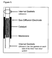
- films made of elastomers are provided on the surfaces of the membrane that are not covered by the electrode which simultaneously constitute the gasket to the bipolar plates and the outer space.
- DE 10235360 describes a membrane electrode unit that contains polyimide layers for sealing. These layers have a uniform thickness such that the boundary area is thinner than the area being in contact with the membrane.
- the membrane electrode units mentioned above are generally connected with planar bipolar plates which include channels for a flow of gas milled into the plates.
- a gasket is inserted between the gasket of the membrane electrode units and the bipolar plates which is usually made of PTFE. To avoid such gasket more sophisticated bipolar plates are required which causes higher costs. It was found in long-term tests that such a structure is likewise more stable than before, however, in long term testing of more than 3000 hours the stability still needs to be improved further.
- the sub gasket serves the purpose of minimizing expensive membrane, provides a stable surface for sealing gaskets that make a gas-tight seal around the MEA and with the bipolar plates, while at the same time must be stable under acidic, thermal, and electrochemical forces that promote degradation.
- a sub gasket as a frame around the MEU provides a certain degree of complexity when alignment of the assembly of electrodes, membrane, and frame. Typically this alignment is accomplished through either highly skilled assemblers, or machines. However, even with highly skilled workers, one may be subject to unwanted variations in alignment; use of machines presents an advantage, but then loss of alignment may occur in time as the machine tools age, lose tolerance and/or corrode in the acid environment of this system.
- the MEU provided should have the following properties:
- the present invention relates to a membrane electrode unit (MEU) having
- the polysulphone forming the polymer frame contains recurring units with linking sulphone groups defined by the general formulae A, B, C, D, E, F, G and/or H: wherein the functional groups R, independently of another, are identical or different and represent aromatic or heteroaromatic groups.
- the functional groups R in formulae A, B, C, D, E, F, G and/or H are 1,2-phenylene, 1,3-phenylene, 1,4-phenylene, 4,4'-biphenyl, pyridine, quinoline, naphthalene or phenanthrene.
- functional groups R in formulae A, B, C, D, E, F, G and/or H are 1,2-phenylene, 1,3-phenylene, 1,4-phenylene or4,4'-biphenyl.
- functional groups R in formulae C and H is 1,4-phenylene.
- polysulphones preferred within the scope of the present invention include homopolymers and copolymers, for example random copolymers.
- Particularly preferred polysulphones comprise recurring units of the formulae H to O:
- the polysulphones described above can be obtained commercially under the trade names ®Victrex 200 P, ®Victrex 720 P, ®Ultrason E, ®Ultrason S, ®Ultrason P, ®Mindel, ®Radel A, ®Radel R, ®Victrex HTA, ®Astrel and ®Udel.
- suitable polymer electrolyte membranes are known per se.
- membranes are employed for this, which comprise acids, wherein the acids may be covalently bound to the polymers or imbibed and coordinated through acid-base interaction with the polymer forming the membrane.
- acids may be covalently bound to the polymers or imbibed and coordinated through acid-base interaction with the polymer forming the membrane.
- any flat material being doped with an acid can be used as suitable membrane.
- These membranes can, amongst other methods, be produced by swelling flat materials, for example a polymer film, with a fluid comprising acidulous compounds, or by manufacturing a mixture of polymers and acidulous compounds and the subsequent formation of a membrane by forming a flat structure and following solidification in order to form a membrane.
- Preferred polymers include, amongst others, polyolefines, such as poly(chloroprene), polyacetylene, polyphenylene, poly(p-xylylene), polyarylmethylene, polystyrene, polymethylstyrene, polyvinyl alcohol, polyvinyl acetate, polyvinyl ether, polyvinyl amine, poly(N-vinyl acetamide), polyvinyl imidazole, polyvinyl carbazole, polyvinyl pyrrolidone, polyvinyl pyridine, polyvinyl chloride, polyvinylidene chloride, polytetrafluoroethylene, polyhexafluoropropylene, copolymers of PTFE with hexafluoropropylene, with perfluoropropylvinyl ether, with trifluoronitrosomethane, with carbalkoxyperfluoroalkoxyvinyl ether, polychlorotrifluoroethylene, poly
- Polymeric C-S-bounds in the backbone for example, polysulphide ether, polyphenylenesulphide, polyethersulphone, polysulphone, polymeric C-N bonds in the backbone, for example polyimines, polyisocyanides, polyetherimine, polyetherimides, polyaniline, polyaramides, polyamides, polyhydrazides, polyurethanes, polyimides, polyazoles, polyazole ether ketone, polyazines; liquid crystalline polymers in particular Vectra as well as inorganic polymers, such as polysilanes, polycarbosilanes, polysiloxanes, polysilicic acid, polysilicates, silicons, polyphosphazenes and polythiazyl.
- alkaline polymers wherein this particularly applies to membranes doped with acids.
- Almost all known polymer membranes that are able to transport protons come into consideration as alkaline polymer membranes doped with acid.
- acids are preferred, which are able to transport the protons without additional water, for example by means of the so called Grotthus mechanism.
- alkaline polymer preferably an alkaline polymer with at least one nitrogen atom in a repeating unit is used.
- the repeating unit in the alkaline polymer contains an aromatic ring with at least one nitrogen atom.
- the aromatic ring is preferably a five-membered or six-membered ring with one to three nitrogen atoms, which may be fused to another ring, in particular another aromatic ring.
- high-temperature-stable polymers which contain at least one nitrogen, oxygen and/or sulphur atom in one or in different repeating units.
- a high-temperature-stable polymer is a polymer which, as polymer electrolyte, can be operated over the long term in a fuel cell at temperatures above 120°C.
- Over the long term means that a membrane according to the invention can be operated for at least 100 hours, preferably at least 500 hours, at a temperature of at least 80°C, preferably at least 120°C, particularly preferably at least 160°C, without the performance being decreased by more than 50% based on the initial performance, which can be measured according to the method described in WO 01/18894 A2 .
- polymers can be used individually or as a mixture (blend).
- blends which contain polyazoles and/or polysulphones.
- the preferred blend components are polyethersulphone, polyether ketone, and polymers modified with sulphonic acid groups, as described in the European patent application EP-A-1,337,319 and German patent application DE-A-10245451 .
- Polyazoles constitute a particularly preferred group of alkaline polymers.
- An alkaline polymer based on polyazole contains recurring azole units of the general formula (I) and/or (II) and/or (III) and/or (IV) and/or (V) and/or (VI) and/or (VII) and/or (VIII) and/or (IX) and/or (X) and/or (XI) and/or (XII) and/or (XIII) and/or (XIV) and/or (XV) and/or (XVI) and/or (XVII) and/or (XVIII) and/or (XIX) and/or (XX) and/or (XXI) and/or (XXII) in which
- azole means that the polymer has at least one repeating unit comprising an aromatic ring in which at least one nitrogen heteroatom is present in said aromatic ring. Said at least one nitrogen heteroatom typically is bonded to hydrogen.
- Preferred aromatic or heteroaromatic groups are derived from benzene, naphthalene, biphenyl, diphenyl ether, diphenylmethane, diphenyldimethylmethane, bisphenone, diphenylsulphone, chinoline, pyridine, bipyridine, pyridazin, pyrimidine, pyrazine, triazine, tetrazine, pyrole, pyrazole, anthracene, benzopyrrole, benzotriazole, benzooxathiadiazole, benzooxadiazole, benzopyridine, benzopyrazine, benzopyrazidine, benzopyrimidine, benzotriazine, indolizine, quinolizine, pyridopyridine, imidazopyrimidine, pyrazinopyrimidine, carbazole, aziridine, phenazine, benzoquinoline, phenoxazine, pheno
- Ar 1 , Ar 4 , Ar 6 , Ar 7 , Ar 8 , Ar 9 , Ar 10 , Ar 11 can have any substitution pattern, in the case of phenylene, for example, Ar 1 , Ar 4 , Ar 6 , Ar 7 , Ar 8 , Ar 9 , Ar 10 , Ar 11 can be ortho-, meta- and para-phenylene. Particularly preferred groups are derived from benzene and biphenylene, which may also be substituted.
- Preferred alkyl groups are short-chain alkyl groups having from 1 to 4 carbon atoms, such as, e.g., methyl, ethyl, n-propyl or isopropyl and t-butyl groups.
- Preferred aromatic groups are phenyl or naphthyl groups.
- the alkyl groups and the aromatic groups can be substituted.
- substituents are halogen atoms such as, e.g., fluorine, amino groups, hydroxyl groups or short-chain alkyl groups such as, e.g., methyl or ethyl groups.
- Polyazoles having recurring units of the formula (I) are preferred wherein the radicals X within one recurring unit are identical.
- the polyazoles can in principle also have different recurring units wherein their radicals X are different, for example. It is preferable, however, that a recurring unit has only identical radicals X.
- polyazole polymers are polyimidazoles, polybenzothiazoles, polybenzoxazoles, polyoxadiazoles, polyquinoxalines, polythiadiazoles, poly(pyridines), poly(pyrimidines) and poly(tetrazapyrenes).
- the polymer containing recurring azole units is a copolymer or a blend which contains at least two units of the formulae (I) to (XXII) which differ from one another.
- the polymers can be in the form of block copolymers (diblock, triblock), random copolymers, periodic copolymers and/or alternating polymers.
- the polymer containing recurring azole units is a copolymer as described in U.S. Patent Application Serial Number 13/769,413 which entire scope is hereby incorporated by reference.
- the polymer containing recurring azole units is a polyazole, which only contains units of the formulae (I) and/or (II).
- the number of recurring azole units in the polymer is preferably an integer greater than or equal to 10.
- Particularly preferred polymers contain at least 100 recurring azole units.
- polymers containing recurring benzimidazole units are preferred.
- Some examples of the most appropriate polymers containing recurring benzimidazole units are represented by the following formulae: where n and m are each an integer greater than or equal to 10, preferably greater than or equal to 100.
- the polyazoles used are characterized by a high molecular weight. Measured as the intrinsic viscosity, this is preferably at least 0.2 dl/g, preferably 0.8 to 10 dl/g, in particular 1 to 10 dl/g.
- aromatic carboxylic acids used according to the invention are, among others, dicarboxylic and tricarboxylic acids and tetracarboxylic acids or their esters or their anhydrides or their acid chlorides.
- aromatic carboxylics acid likewise also comprises heteroaromatic carboxylic acids.
- the aromatic dicarboxylic acids are isophthalic acid, terephthalic acid, phthalic acid, 5-hydroxyisophthalic acid, 4-hydroxyisophthalic acid, 2-hydroxyterephthalic acid, 5-aminoisophthalic acid, 5-N,N-dimethylaminoisophthalic acid, 5-N,N-diethylaminoisophthalic acid, 2,5-dihydroxyterephthalic acid, 2,6-dihydroxyisophthalic acid, 4,6-dihydroxyisophthalic acid, 2,3-dihydroxyphthalic acid, 2,4-dihydroxyphthalic acid, 3,4-dihydroxyphthalic acid, 3-fluorophthalic acid, 5-fluoroisophthalic acid, 2-fluoroterephthalic acid, tetrafluorophthalic acid, tetrafluoroisophthalic acid, tetrafluoroterephthalic acid, 1,4-naphthalenedicarboxylic acid, 1,5-naphthalenedicarboxylic acid, 2,6-n
- aromatic tricarboxylic acids, tetracarboxylic acids or their C1-C20 alkyl esters or C5-C12 aryl esters or their acid anhydrides or their acid chlorides are preferably 1,3,5-benzenetricarboxylic acid (trimesic acid), 1,2,4-benzenetricarboxylic acid (trimellitic acid), (2-carboxyphenyl)iminodiacetic acid, 3,5,3'-biphenyltricarboxylic acid; 3,5,4'-biphenyltricarboxylic acid.
- aromatic tetracarboxylic acids or their C1-C20 alkyl esters or C5-C12 aryl esters or their acid anhydrides or their acid chlorides are preferably 3,5,3',5'-biphenyltetracarboxylic acid, 1,2,4,5-benzenetetracarboxylic acid, benzophenonetetracarboxylic acid, 3,3',4,4'-biphenyltetracarboxylic acid, 2,2',3,3'-biphenyltetracarboxylic acid, 1,2,5,6-naphthalenetetracarboxylic acid, 1,4,5,8-naphthalenetetracarboxylic acid.
- heteroaromatic carboxylic acids are heteroaromatic dicarboxylic acids and tricarboxylic acids and tetracarboxylic acids or their esters or their anhydrides.
- Heteroaromatic carboxylic acids are understood to mean aromatic systems which contain at least one nitrogen, oxygen, sulphur or phosphor atom in the aromatic group.
- pyridine-2,5-dicarboxylic acid pyridine-3,5-dicarboxylic acid, pyridine-2,6-dicarboxylic acid, pyridine-2,4-dicarboxylic acid, 4-phenyl-2,5-pyridinedicarboxylic acid, 3,5-pyrazoledicarboxylic acid, 2,6-pyrimidinedicarboxylic acid, 2,5-pyrazinedicarboxylic acid, 2,4,6-pyridinetricarboxylic acid, benzimidazole-5,6-dicarboxylic acid and their C1-C20 alkyl esters or C5-C12 aryl esters or their acid anhydrides or their acid chlorides are used.
- the content of tricarboxylic acids or tetracarboxylic acids is between 0 and 30 mol-%, preferably 0.1 and 20 mol-%, in particular 0.5 and 10 mol-%.
- aromatic and heteroaromatic diaminocarboxylic acids used are preferably diaminobenzoic acid and its monohydrochloride and dihydrochloride derivatives.
- mixtures of at least 2 different aromatic carboxylic acids are used.
- mixtures are used which also contain heteroaromatic carboxylic acids additionally to aromatic carboxylic acids.
- the mixing ratio of aromatic carboxylic acids to heteroaromatic carboxylic acids is from 1:99 to 99:1, preferably 1:50 to 50:1.
- N-heteroaromatic dicarboxylic acids are in particular mixtures of N-heteroaromatic dicarboxylic acids and aromatic dicarboxylic acids.
- Non-limiting examples of these are isophthalic acid, terephthalic acid, phthalic acid, 2,5-dihydroxyterephthalic acid, 2,6-dihydroxyisophthalic acid, 4,6-dihydroxyisophthalic acid, 2,3-dihydroxyphthalic acid, 2,4-dihydroxyphthalic acid, 3,4-dihydroxyphthalic acid, 1,4-naphthalenedicarboxylic acid, 1,5-naphthalenedicarboxylic acid, 2,6-naphthalenedicarboxylic acid, 2,7-naphthalenedicarboxylic acid, diphenic acid, 1,8-dihydroxynaphthalene-3,6-dicarboxylic acid, diphenyl ether-4,4'-dicarboxylic acid, benzophenone-4,4'-dicarboxylic acid, diphen
- the preferred aromatic tetraamino compounds include, amongst others, 3,3',4,4'-tetraaminobiphenyl, 2,3,5,6-tetraaminopyridine, 1,2,4,5-tetraaminobenzene, 3,3',4,4'-tetraaminodiphenyl sulphone, 3,3',4,4'-tetraaminodiphenyl ether, 3,3',4,4'-tetraaminobenzophenone, 3,3',4,4'-tetraaminodiphenylmethane and 3,3',4,4'-tetraaminodiphenyldimethylmethane as well as their salts, in particular their monohydrochloride, dihydrochloride, trihydrochloride and tetrahydrochloride derivatives.
- Preferred polybenzimidazoles are commercially available.
- Preferred polymers include polysulphones, in particular polysulphone having aromatic and/or heteroaromatic groups in the backbone.
- preferred polysulphones and polyethersulphones have a melt volume rate MVR 300/21.6 of less than or equal to 40 cm 3 /10 min, in particular less than or equal to 30 cm 3 /10 min and particularly preferably less than or equal to 20 cm 3 /10 min, measured in accordance with ISO 1133.
- MVR 300/21.6 of less than or equal to 40 cm 3 /10 min, in particular less than or equal to 30 cm 3 /10 min and particularly preferably less than or equal to 20 cm 3 /10 min, measured in accordance with ISO 1133.
- the number average of the molecular weight of the polysulphones is greater than 30,000 g/mol.
- the polymers based on polysulphone include in particular polymers having recurring units with linking sulphone groups according to the general formulae A, B, C, D, E, F, G and/or H: wherein the functional groups R, independently of another, are identical or different and represent aromatic or heteroaromatic groups.
- the functional groups R in formulae A, B, C, D, E, F, G and/or H are 1,2-phenylene, 1,3-phenylene, 1,4-phenylene, 4,4'-biphenyl, pyridine, quinoline, naphthalene or phenanthrene.
- functional groups R in formulae A, B, C, D, E, F, G and/or H are 1,2-phenylene, 1,3-phenylene, 1,4-phenylene or4,4'-biphenyl.
- functional groups R in formulae C and H is 1,4-phenylene.
- polysulphones preferred within the scope of the present invention include homopolymers and copolymers, for example random copolymers.
- Particularly preferred polysulphones comprise recurring units of the formulae H to O:
- the polysulphones described above can be obtained commercially under the trade names ®Victrex 200 P, ®Victrex 720 P, ®Ultrason E, ®Ultrason S, ®Ultrason P, ®Mindel, ®Radel A, ®Radel R, ®Victrex HTA, ®Astrel and ®Udel.
- polyether ketones polyether ketone ketones
- polyether ether ketones polyether ketone ketones
- polyaryl ketones are particularly preferred. These high-performance polymers are known per se and can be obtained commercially under the trade names Victrex® PEEKTM, ®Hostatec, ®Kadel.
- a polymer preferably a polyazole can be dissolved in an additional step in polar, aprotic solvents such as dimethylacetamide (DMAc) and a film is produced by means of classical methods.
- DMAc dimethylacetamide
- the film thus obtained can be treated with a washing liquid as is described in European patent application EP-A-1,368,845 . Due to the cleaning of the polyazole film to remove residues of solvent described in the German patent application, the mechanical properties of the film are surprisingly improved. These properties include in particular the E-modulus, the tear strength and the break strength of the film.
- the polymer film can have further modifications, for example by cross-linking, as described in European patent application EP-A-1,373,379 or in WO 00/44816 .
- the polymer film used consisting of an alkaline polymer and at least one blend component additionally contains a cross-linking agent, as described in European patent application EP-A-1,425,336 .
- the thickness of the polyazole films can be within wide ranges.
- the thickness of the polyazole film before its doping with an acid is generally in the range of from 5 ⁇ m to 2000 ⁇ m, and particularly preferably 10 ⁇ m to 1000 ⁇ m; however, this should not constitute a limitation.
- acids include all known Lewis- und Bransted acids, preferably inorganic Lewis- und Bransted acids.
- heteropolyacids define inorganic polyacids with at least two different central atoms formed of weak, polyalkaline oxygen acid of a metal (preferably Cr, MO, V, W) and a non-metal (preferably As, I, P, Se, Si, Te) as partial mixed anhydrids.
- a metal preferably Cr, MO, V, W
- a non-metal preferably As, I, P, Se, Si, Te
- the degree of doping can influence the conductivity of the polyazole film.
- the conductivity increases with rising concentration of the doping substance until a maximum value is reached.
- the degree of doping is given as mole of acid per mole of repeating unit of the polymer.
- a degree of doping between 3 and 50, particularly between 5 and 40 is preferred.
- Particularly preferred doping substances are phosphoric and sulphuric acids, or compounds releasing these acids for example during hydrolysis, respectively.
- a very particularly preferred doping substance is phosphoric acid (H 3 PO 4 ).
- highly concentrated acids are generally used.
- the concentration of the phosphoric acid can preferably be at least 50% by weight, particularly at least 20% by weight, based on the weight of the doping substance.
- proton conductive membranes can be obtained by a method comprising the steps:
- doped polyazole films can be obtained by a method comprising the steps:
- step A The aromatic or heteroaromatic carboxylic acids and tetraamino compounds to be employed in step A) have been described above.
- the polyphosphoric acid used in step I) and step A) is a customary polyphosphoric acid as is available, for example, from Riedel-de Haen.
- the polyphosphoric acids H n+2 P n O 3n+1 (n>1) usually have a concentration of at least 83%, calculated as P 2 O 5 (by acidimetry). Instead of a solution of the monomers, it is also possible to produce a dispersion/suspension.
- the mixture produced in step A) has a weight ratio of polyphosphoric acid to the sum of all monomers of from 1:10,000 to 10,000:1, preferably 1:1,000 to 1,000:1, in particular 1:100 to 100:1.
- the layer formation in accordance with step B) is performed by means of measures known per se (pouring, spraying, application with a doctor blade) which are known from the prior art of polymer film production. Every support that is considered as inert under the conditions is suitable as a support.
- phosphoric acid conc. phosphoric acid, 85%
- the viscosity can be adjusted to the desired value and the formation of the membrane be facilitated.
- the layer produced in accordance with step B) has a thickness of 20 to 4000 ⁇ m, preferably of 30 to 3500 ⁇ m, in particular of 50 to 3000 ⁇ m.
- step A) also contains tricarboxylic acids or tetracarboxylic acid, branching/cross-linking of the formed polymer is achieved therewith. This contributes to an improvement in the mechanical property.
- the treatment can be effected to the extent that the membrane is self-supporting so that it can be detached from the support without any damage.
- step C The flat structure obtained in step B) is, in accordance with step C), heated to a temperature of up to 350°C, preferably up to 280°C and particularly preferably in the range of 200°C to 250 °C.
- the inert gases to be employed in step C) are known to those in the field. Particularly nitrogen, as well as noble gases, such as neon, argon and helium belong to this group.
- the formation of oligomers and polymers can already be brought about by heating the mixture resulting from step A) to a temperature of up to 350°C, preferably up to 280°C. Depending on the selected temperature and duration, it is than possible to dispense partly or fully with the heating in step C).
- This variant also subject of the present invention.
- the treatment of the membrane in step D) is performed at temperatures in the range of 0°C to 150°C, preferably at temperatures between 10°C and 120°C, in particular between room temperature (20°C) and 90°C, in the presence of moisture or water and/or steam and/or water-containing phosphoric acid of up to 85%.
- the treatment is preferably performed at normal pressure, but can also be carried out with action of pressure. It is essential that the treatment takes place in the presence of sufficient moisture whereby the polyphosphoric acid present contributes to the solidification of the membrane by means of partial hydrolysis with formation of low molecular weight polyphosphoric acid and/or phosphoric acid.
- the partial hydrolysis of the organic phosphoric acid in step D) leads to a solidification of the membrane and a reduction in the layer thickness and the formation of a membrane having a thickness between 15 and 3000 ⁇ m, preferably between 20 and 2000 ⁇ m, in particular between 20 and 1500 ⁇ m, which is self-supporting.
- the intramolecular and intermolecular structures (interpenetrating networks IPN) that, in accordance with step B), are present in the polyphosphoric acid layer lead to an ordered membrane formation in step C), which is responsible for the special properties of the membrane formed.
- the upper temperature limit for the treatment in accordance with step D) is typically 150°C. With extremely short action of moisture, for example from overheated steam, this steam can also be hotter than 150°C. The duration of the treatment is substantial for the upper limit of the temperature.
- the partial hydrolysis (step D) can also take place in climatic chambers where the hydrolysis can be specifically controlled with defined moisture action.
- the moisture can be specifically set via the temperature or saturation of the surrounding area in contact with it, for example gases such as air, nitrogen, carbon dioxide or other suitable gases, or steam.
- gases such as air, nitrogen, carbon dioxide or other suitable gases, or steam.
- the duration of the treatment depends on the parameters chosen as aforesaid.
- the duration of the treatment depends on the thickness of the membrane.
- the duration of the treatment amounts to between a few seconds to minutes, for example with the action of overheated steam, or up to whole days, for example in the open air at room temperature and lower relative humidity.
- the duration of the treatment is 10 seconds to 300 hours, in particular 1 minute to 200 hours.
- the duration of the treatment is 1 to 200 hours.
- the membrane obtained in accordance with step D) can be formed in such a way that it is self-supporting, i.e. it can be detached from the support without any damage and then directly processed further, if applicable.
- the concentration of phosphoric acid and therefore the conductivity of the polymer membrane according to the invention can be set via the degree of hydrolysis, i.e. the duration, temperature and ambient humidity.
- the concentration of the phosphoric acid is given as mole of acid per mole of repeating unit of the polymer.
- Membranes with a particularly high concentration of phosphoric acid can be obtained by the method comprising the steps A) to D).
- a concentration of 10 to 50 mol of phosphoric acid related to a repeating unit of formula (I) for example polybenzimidazole
- Only with very much difficulty or not at all is it possible to obtain such high degrees of doping (concentrations) by doping polyazoles with commercially available orthophosphoric acid.
- doped polyazole films are produced by using phosphoric acid
- the production of these films can be carried out by a method comprising the following steps:
- a membrane particularly a membrane based on polyazoles, can further be cross-linked at the surface by action of heat in the presence of atmospheric oxygen. This hardening of the membrane surface further improves the properties of the membrane.
- the membrane can be heated to a temperature of at least 150°C, preferably at least 200°C and particularly preferably at least 250°C.
- the oxygen concentration usually is in the range of 5 to 50% by volume, preferably 10 to 40% by volume; however, this should not constitute a limitation.
- IR infrared, i.e. light having a wavelength of more than 700 nm
- NIR near-IR, i.e. light having a wavelength in the range of about 700 to 2000 nm and an energy in the range of about 0.6 to 1.75 eV
- ß-ray irradiation is from 5 and 200 kGy.
- the duration of the cross-linking reaction can be within a wide range. In general, this reaction time lies in the range from 1 second to 10 hours, preferably 1 minute to 1 hour, without this being intended to represent any limitation.
- the thickness of the polymer electrolyte membrane used in the present invention is from 50 to 1,000 ⁇ m, preferably from 100 to 500 ⁇ m.
- Particularly preferred polymer membranes show a high performance.
- the reason for this is in particular improved proton conductivity. This is at least 100 mS/cm, preferably at least 110 mS/cm, in particular at least 120 mS/cm at temperatures of 120°C, preferably of 160°C. These values are achieved without moistening here.
- the membrane electrode unit according to the invention has two gas diffusion layers which are separated by the polymer electrolyte membrane.
- Flat, electrically conductive and acid-resistant structures are commonly used for this. These include, for example, woven or non-woven textile surfaces comprising graphite and/or carbon fibers.
- Preferred are graphite-fibre paper, carbon-fibre paper, graphite fabric and/or paper which was rendered conductive by addition of carbon black.
- Most preferred are non-woven, in particular papers.
- this layer has a thickness in the range of from 80 ⁇ m to 2000 ⁇ m, in particular 100 ⁇ m to 1000 ⁇ m and particularly preferably 150 ⁇ m to 500 ⁇ m.
- At least one of the gas diffusion layers can be comprised of a compressible material.
- a compressible material is characterized by the property that the gas diffusion layer can be compressed by pressure by at least 2% it's thickness, and in particular 5%-30% of its original thickness without losing its integrity.
- This property is generally exhibited by a gas diffusion layer made of graphite fabric and/or paper which was rendered conductive by addition of carbon black.
- the limitation of at least on compressible gas diffusion layers can be obviated by selection of a new sub gasket design.
- the catalyst layer(s) contain(s) catalytically active substances. These include, amongst others, precious metals of the platinum group, i.e. Pt, Pd, Ir, Rh, Os, Ru, or also the precious metals Au and Ag. Furthermore, alloys of the above-mentioned metals may also be used. Additionally, at least one catalyst layer can contain alloys of the elements of the platinum group with non-precious metals, such as for example Fe, Co, Ni, Cr, Mn, Zr, Ti, Ga, V, etc. Furthermore, the oxides of the above-mentioned precious metals and/or non-precious metals can also be employed.
- the catalytically active particles comprising the above-mentioned substances may be employed as metal powder, so-called black precious metal, in particular platinum and/or platinum alloys.
- Such particles generally have a size in the range from 5 nm to 200 nm, preferably in the range from 7 nm to 100 nm.
- the metals can also be employed on a support material.
- this support comprises carbon which particularly may be used in the form of carbon black, graphite or graphitised carbon black.
- electrically conductive metal oxides such as for example, SnO x , TiO x , or phosphates, such as e.g. FePO x , NbPO x , Zr y (PO x ) z , can be used as support material.
- the indices x, y and z designate the oxygen or metal content of the individual compounds which can lie within a known range as the transition metals can be in different oxidation stages.
- the content of these metal particles on a support is generally in the range of 1 to 80% by weight, preferably 5 to 60% by weight and particularly preferably 10 to 50% by weight; however, this should not constitute a limitation.
- the particle size of the support in particular the size of the carbon particles, is preferably in the range of 20 to 1000 nm, in particular 30 to 100 nm.
- the size of the metal particles present thereon is preferably in the range of 1 to 20 nm, in particular 1 to 10 nm and particularly preferably 2 to 6 nm.
- the sizes of the different particles represent mean values and can be determined via transmission electron microscopy or X-ray powder diffractometry.
- the catalytically active particles set forth above can generally be obtained commercially.
- the catalytically active layer may contain customary additives. These include, amongst others, fluoropolymers, such as e.g. polytetrafluoroethylene (PTFE) and fluorinated ethylene polypropylene (FEP) proton-conducting ionomers and surface-active substances.
- fluoropolymers such as e.g. polytetrafluoroethylene (PTFE) and fluorinated ethylene polypropylene (FEP) proton-conducting ionomers and surface-active substances.
- the weight ratio of fluoropolymer to catalyst material comprising at least one precious metal and optionally one or more support materials is greater than 0.1, this ratio preferably lying within the range of 0.2 to 0.6.
- the catalyst layer has a thickness in the range of 1 to 1000 ⁇ m, in particular from 5 to 500, preferably from 10 to 300 ⁇ m.
- This value represents a mean value, which can be determined by averaging the measurements of the layer thickness from photographs that can be obtained with a scanning electron microscope (SEM).
- the catalyst layer is in general not self-supporting but is usually applied to the gas diffusion layer and/or the membrane, preferably the catalyst layer is on the gas diffusion layer, thus forming the gas diffusion electrode.
- the content of precious metals of the catalyst layer is 0.1 to 10.0 mg/cm 2 , preferably 0.3 to 6.0 mg/cm 2 and particularly preferably 0.3 to 3.0 mg/cm 2 . These values can be determined by elemental analysis of a flat sample.
- the electrochemically active surface of the catalyst layer defines the surface which is in contact with the polymer electrolyte membrane and at which the redox reactions set forth above can take place.
- the present invention allows for the formation of particularly large electrochemically active surfaces.
- the size of this electrochemically active surface is at least 2 cm 2 , in particular at least 5 cm 2 and preferably at least 10 cm 2 ; however, this should not constitute a limitation.
- the instant method is particular suitable for larger electrochemically active surfaces which are at least 100 cm 2 , preferably at least 200 cm 2 .
- the membrane electrode unit according to the invention having:
- the thickness of the polymer frame acting as subgasket in the present invention is from 20 to 300 ⁇ m, preferably from 30 to 100 ⁇ m.
- Said frame is preferably a polymer film having said thickness.
- the polymer frame subgasket overlaps with the peripheral area of the gas diffusion layer/catalyst layer, said overlap being preferably at least 1 mm, preferably at least 1.5mm, most preferred at least 2mm. Since the overlap reduces the electrochemical active area of the MEU, the upper limit is merely depending on the economics. The skilled worker will select such upper limit on the particular field in which the MEU are used.
- the range of appropriate overlap between GDE and subgasket can range between 1.5mm to 15mm, and preferably from 2.5 to 5mm. The particular overlap selected is dependent on the overall length and width of the MEU and final application.
- the polysulphone forming the polymer frame subgasket exhibit a long-term service temperature of at least 160°C, preferable 180°C, more preferred at least 190°C, more preferably at least 220°C and most preferably at least 250°C, measured in accordance with MIL-P-46112B, paragraph 4.4.5.
- the polysulphone polymer frame subgasket is a film having a tensile strength of at least 6 N/mm 2 , preferably at least 7 N/mm 2 , measured at 80°C, preferably 160°C, and an elongation of 100%.
- the polymer frame subgasket does not requires any additional coatings such as a meltable polymer coating.
- additional coatings can be present and are preferably fluoropolymer, such as for example poly(tetrafluoroethylen-co-hexafluoropropylene) FEP, polyvinylidenefluoride PVDF, perfluoroalkoxy polymer PFA, poly(tetrafluoroethylen-co-perfluoro(methylvinylether)) MFA.
- fluoropolymer such as for example poly(tetrafluoroethylen-co-hexafluoropropylene) FEP, polyvinylidenefluoride PVDF, perfluoroalkoxy polymer PFA, poly(tetrafluoroethylen-co-perfluoro(methylvinylether)) MFA.
- These polymers are in many cases commercially available, for example under the trade names Hostafon®, Hyf
- the polysulphone polymer frame subgasket is usually in contact with electrically conductive separator plates which are typically provided with flow field channels on the sides facing the gas diffusion layers to allow for the distribution of reactant fluids.
- the separator plates are usually manufactured of graphite or conductive, thermally stable plastic.
- the polymer frame seals the gas spaces against the outside. Furthermore, the polymer frame generally also seals the gas spaces between anode and cathode.
- the polysulphone polymer frame subgasket contacts and overlaps the catalyst layer and / or the gas diffusion layer via the edge surfaces.
- the edge surfaces are those surfaces that are formed of the thickness of the electrode or the frame and the corresponding length or width of these layers.
- the polymer frame subgasket contacts and overlaps the catalyst layer and / or the gas diffusion layer via the surface that is defined by the length and the width of the frame or the electrode, respectively.
- the polysulphone polymer frame subgasket allows for a minimum controlled compression of the polymer electrolyte membrane
- the polysulphone material of the polymer frame is a material which decreases in its thickness over a period of 5 hours, particularly preferably 10 hours, by not more than 5%, in particular not more than 2%, preferably not more than 1%, at a temperature of 120°C, particularly preferably 160°C, and a pressure of 10 N/mm 2 , in particular 15 N/mm 2 and particularly preferably 20 N/mm 2 .
- the aforementioned compression determined in accordance with the method disclosed in WO 2006/008158 .
- the thickness of the polymer frame and the polymer electrolyte membrane are about equal in the final MEU. Most typically the polymer electrolyte membrane has a higher thickness than the polymer frame. This allows to place polymer electrolyte membrane in the aperture formed by the polymer frame which are smaller than the aperture and be pressing the layered materials to from the final laminated MEU such space between the polymer frame and the polymer electrolyte membrane is filled by the compression and deformation of the polymer electrolyte membrane.
- the term "about equal" in the present invention means that thickness of the polysulphone polymer frame subgasket corresponds to the thickness of the polymer electrolyte membrane +/- 5 ⁇ m or less, preferably +/- 2 ⁇ m or less.
- a further embodiment of the instant invention includes two additional polymer frame subgasket films being arranged between the surface of the aforementioned polysulphone polymer frame subgasket and the gas diffusion layer being in contact with a catalyst layer, the inner area of said additional polymer frame subgasket films overlaps with the outer peripheral area of the polymer electrolyte membrane, said overlap being preferably at least 1 mm, preferably at least 1.5mm, most preferred at least 2mm, and the outer area of said additional polymer frame subgasket films reaches over the top surface of the polysulphone polymer frame subgasket but does not extent outwards the polysulphone polymer frame subgasket.
- the additional polymer frame subgasket films are made from the same polysulphones materials described for the polysulphone polymer frame subgaskets and preferably are made from the same polysulphones material.
- the thickness of an additional polymer frame is from20 to 300 ⁇ m, preferably from 30 to 100 ⁇ m, and can control the compression during lamination. Therefore the additional polymer frame is 5 to 50% thinner as the polymer frame.
- the preferred embodiments of the additional polymer frame are the same as the preferred embodiments for the polysulphone polymer frame subgasket described above.
- the present invention further relates to a process for the manufacture of a membrane electrode unit (MEU) according to the instant invention by known processes.
- MEU membrane electrode unit
- the MEU according to the instant invention is manufactures as described in U.S Patent Application SN 61/812,268 which disclosure is hereby incorporated by references.
- Ionic conductivities were measured via a four-probe through-plane bulk measurement using an AC Zahner IM6e impedance spectrometer that scanned a frequency range from 1 Hz to 100 KHz.
- a rectangular sample of membrane (3.5 cm x 7.0 cm) was placed in a glass or polysulfone cell with four platinum wire current collectors.
- Two outer electrodes set 6.0 cm apart supplied current to the cell, while the two inner electrodes 2.0 cm apart on opposite sides of the membrane measured the voltage drop.
- the two outer electrodes are placed on opposite sides of the membrane and the two inner electrodes are arranged in the same manner.
- D was the distance between the two test current electrodes
- L was the thickness of the membrane
- B was the width of the membrane
- R was the measured resistance.
- the membrane contains no additional proton-conducting fillers.
- Fuel cell performance was measured in 50 cm 2 (active area 45.15 cm 2 ) single stack fuel cells using test stations obtained from Plug Power or purchased from Fuel Cell Technologies. Polarization curves were obtained at various temperatures (120-180°C) with hydrogen as a fuel and different oxidants (air or oxygen gas). Fuel cells were operated for at least 100 hours (break-in period) at 0.2 A/cm 2 at 180°C before measurement of polarization curves. Long term stability testing was performed under static current and temperature conditions of 0.2 A/cm 2 and 180°C with a constant flow rate of hydrogen (1.2 stoichiometric ratio) and air (2.0 stoichiometric ratio).
- the inherent viscosity also referred to as intrinsic viscosity, was measured by placing a small amount of pulverized polymer (washed with distilled water until neutral to remove any mineral acids and dried for 12 hours at 120-130°C)'. Solutions for inherent viscosity measurement were prepared by dissolving the neutralized polymer in concentrated sulfuric acid (96%) at a concentration of 0.2 g/dL.
- the composition of the membrane was determined by titration with 0.1 M sodium hydroxide.
- the 0.1 M sodium hydroxide solution was prepared by dissolving 4 g sodium hydroxide in 1 liter distilled water and standardized by titration with a known amount of potassium hydrogen phthalate (predried at 110 oC for 1 hour). At least three circular samples with a diameter of 2 cm were cut from the bulk membrane. Every sample was weighed to obtain the initial weight, and then placed in 20 mL of distilled water and allowed to stir for at least 30 minutes. The samples were titrated using a Metrohm 716 DMS Titrino titrator. The first equivalence point was used to determine the volume of sodium hydroxide necessary for neutralization. The samples were washed thoroughly with distilled water and dried in a vacuum oven at 110 °C for at least eight hours. The samples were allowed to cool to room temperature in the vacuum oven before removal and were weighed to obtain the dry weight of the polymer.
- the thickness of the layers is determined with a digital thickness tester from the company Mitutoyo.
- the initial pressure of the two circular flat contact surfaces during measurement is 1 PSI, the diameter of the contact surface is 1 cm.
- Example 1 Control Two commercially available gas diffusion electrodes produced according to patent application US 6,103,077 are used whereby the anode contains a platinum on carbon catalyst and the cathode contains a platinum alloy on carbon catalyst. These electrodes are cut to 72mm x 72mm.
- a proton-conducting membrane produced according to the patent application EP-A-1,379,573 is used and cut to dimensions 72mm x 72mm
- a first polymer frame gasket made of Kapton with a thin FEP coating is cut with outer dimensions 110mm x 110mm and cut-out (aperture) 67.2mm x 67.2mm.
- the pre-cut Kapton piece is laminated to the electrode piece whereby 2.4mm of the edge of the electrode is in contact to the inner edge of the Kapton piece. This is performed for both anode and cathode.
- These electrode-subgasket assemblies are placed with a membrane and laminated to form the membrane electrode unit.
- the cut-out (aperture) of the first polymer frame gasket has a size of 73mm x 73mm so that the clearance of the frame and the electrode is 0.5mm on each side and outer dimensions of 110mm x 110mm
- a ®Kapton sheet on top and bottom of MEU is to protect tray and platens from any acid that may come out. Thickness is typically 40 ⁇ m for ®Kapton sheets.
- the arrangement is placed in a press (Tonitechnik, 500mm X 600mm, , Titanium tray is placed onto Steel platens, added below) compressed with each other under defined pressure ( ⁇ 4Mpa based on shim/template combo frame area) and duration (30 seconds) at a temperature of 140°C.
- the active electrode surface is 45.16cm 2 and a MEA similar to Figure 1 is obtained.
- a MEU is made according to the process and materials of Example 1 except Ultrason E is employed as the subgasket.
- a MEU is made according to the process and materials of Example 1 except Ultrason P is employed as the subgasket.
- a proton-conducting membrane produced according to the patent application EP-A-1,379,573 is used and cut to dimesions 72mm x 72mm
- a first polymer frame gasket made of Ultrason P 30 microns thick is cut with outer dimensions 110mm x 110mm and cut-out (aperture) 67.2mm x 67.2mm.
- the pre-cut Ultrason P piece is laminated to the electrode piece whereby 2.4mm of the edge of the electrode is in contact to the inner edge of the Ultrason P piece. This is performed for both anode and cathode.
- a third polymer frame alignment gasket made of Ultrason P 100 microns thick is cut with outer dimensions 110mm x 110mm and cut-out (aperture) 67.2mm x 67.2mm.
- a first electrode-sub gasket assembly is placed on a table and the 100 micron Ultrason P alignment gasket is placed on top.
- a pre-cut membrane is placed inside the 100 micron cavity, followed by placement of the second electrode subgasket assembly. All three Ultrason P materials are laminated with the membrane to form the membrane electrode unit.
- An additional polymer frame gasket made of PFA with a thickness of 400 ⁇ m is made.
- the cut-out (aperture) of the first polymer frame gasket has a size of 73mm x 73mm so that the clearance of the frame and the electrode is 0.5mm on each side and outer dimensions of 110mm x 110mm
- the active electrode surface is 45.16cm 2 and a MEA similar to Figure 5 is obtained.
- Example 5 Use of subgasket to align and control membrane compression A MEU similar to Example 4 is constructed, except the third polymer frame alignment gasket is made of Ultrason P 250 microns thick
- Table 1 summarizes the stability of the polysulfone class of materials when subjected to the thermal and the chemical corrosive forces of phosphoric acid at 180°C. Coupons of material are cut, weighed, and measured prior to continuous immersion in the hot acid and then checked periodically in time. One notes that the polysulfones are the most stable class of materials evaluated.
- FIG. 6 is shows Ultrason P compared to Ultrason E after six polarization cycles whereby the current load is varied from zero to 0.7A/cm 2 .
- MEUs with Ultrason E begin to degrade. This loss of integrity is made more evident after simple life testing as shown in Figure 7 .
- MEUs with Ultrason P, E, and FEP-coated Kapton are run under hydrogen air at 0.2A/cm 2 whereby the voltage is recorded in time.
- the Ultrason E sample developed a catastrophic hydrogen leak while the Kapton MEA degraded more quickly than Ultrason P MEUs.
- an Ultrason P sub gasket can be fashioned into a membrane alignment element, and more importantly, an automatic means to control compression on the membrane over time.
- compressible materials are used for the electrode, and the anode and cathode compress the membrane to a set level determined at fabrication. Since the membrane is >90% phosphoric acid, over time, this high compression can lead to loss of acid from the membrane into the electrodes. Also, during the fabrication step, great care must be maintained to set the compression through shims and a judicious selection of membrane and electrode thicknesses.
- Figure 10 demonstrates that by assembling a MEU as in Example 4 (100 micron Ultrason P as an alignment element), one can maintain consistent compression during assembly. The higher reformate current at >0.5A/cm 2 for the 100 micron spacer element supports this conclusion. The same is found in Figure 11 , now showing the cathode side improvement. Figures 12 and 13 demonstrate similar improvements now with a 250 micron spacer. Finally, Figure 14 shows long term performance, especially the lower trace tracking cell resistence.
Applications Claiming Priority (1)
| Application Number | Priority Date | Filing Date | Title |
|---|---|---|---|
| US201361872792P | 2013-09-02 | 2013-09-02 |
Publications (2)
| Publication Number | Publication Date |
|---|---|
| EP2843743A1 true EP2843743A1 (fr) | 2015-03-04 |
| EP2843743B1 EP2843743B1 (fr) | 2018-03-28 |
Family
ID=51302663
Family Applications (1)
| Application Number | Title | Priority Date | Filing Date |
|---|---|---|---|
| EP14180738.8A Active EP2843743B1 (fr) | 2013-09-02 | 2014-08-13 | Unités d'électrodes à membrane pour piles à combustible à haute température avec une stabilité améliorée |
Country Status (3)
| Country | Link |
|---|---|
| US (1) | US9997791B2 (fr) |
| EP (1) | EP2843743B1 (fr) |
| DK (1) | DK2843743T3 (fr) |
Families Citing this family (3)
| Publication number | Priority date | Publication date | Assignee | Title |
|---|---|---|---|---|
| US11289728B2 (en) | 2017-09-01 | 2022-03-29 | Stryten Critical E-Storage Llc | Segmented frames for redox flow batteries |
| CN113334582A (zh) * | 2021-06-08 | 2021-09-03 | 一汽解放汽车有限公司 | 一种石墨双极板加工装置及加工方法 |
| JP2023002162A (ja) * | 2021-06-22 | 2023-01-10 | 株式会社デンソー | プロトン伝導膜の製造方法 |
Citations (22)
| Publication number | Priority date | Publication date | Assignee | Title |
|---|---|---|---|---|
| WO1992015121A1 (fr) | 1991-02-19 | 1992-09-03 | United States Department Of Energy | Couche catalyseur membrane pour piles a combustible |
| US5464700A (en) | 1991-06-04 | 1995-11-07 | Ballard Power Systems Inc. | Gasketed membrane electrode assembly for electrochemical fuel cells |
| WO1996013872A1 (fr) | 1994-11-01 | 1996-05-09 | Case Western Reserve University | Polymeres conducteurs des protons |
| DE19509748A1 (de) | 1995-03-17 | 1996-10-02 | Deutsche Forsch Luft Raumfahrt | Verfahren zur Herstellung eines Verbundes aus Elektrodenmaterial, Katalysatormaterial und einer Festelektrolytmembran |
| DE19509749A1 (de) | 1995-03-17 | 1996-10-02 | Deutsche Forsch Luft Raumfahrt | Verfahren zur Herstellung eines Verbundes aus Elektrodenmaterial, Katalysatormaterial und einer Festelektrolytmembran |
| DE19757492A1 (de) | 1997-12-23 | 1999-07-01 | Deutsch Zentr Luft & Raumfahrt | Verfahren zur Herstellung von Funktionsschichten für Brennstoffzellen |
| WO2000026982A2 (fr) | 1998-10-30 | 2000-05-11 | Siemens Aktiengesellschaft | Unite membrane-electrode pour pile a combustible a membrane electrolytique polymere, et son procede de production |
| WO2000044816A1 (fr) | 1999-01-27 | 2000-08-03 | Celanese Ventures Gmbh | Procede de production d'un membrane polymerique ponte et pile a combustible |
| US6103077A (en) | 1998-01-02 | 2000-08-15 | De Nora S.P.A. | Structures and methods of manufacture for gas diffusion electrodes and electrode components |
| WO2001018894A2 (fr) | 1999-09-09 | 2001-03-15 | Danish Power Systems Aps | Piles a combustible a membrane electrolytique en polymere |
| JP2001196082A (ja) | 2000-01-07 | 2001-07-19 | Honda Motor Co Ltd | リン酸型燃料電池用電極ユニット |
| EP1337319A1 (fr) | 2000-10-21 | 2003-08-27 | Celanese Ventures GmbH | Nouvelles membranes presentant de meilleures proprietes mecaniques, destinees a un usage dans des piles a combustible |
| EP1368845A1 (fr) | 2001-03-01 | 2003-12-10 | Celanese Ventures GmbH | Membrane polymere, son procede de production et son utilisation |
| EP1373379A2 (fr) | 2001-03-07 | 2004-01-02 | Celanese Ventures GmbH | Procede pour produire une membrane en polymere ponte et cellule electrochimique |
| EP1379573A1 (fr) | 2001-04-09 | 2004-01-14 | Celanese Ventures GmbH | Membrane conductrice de protons et son utilisation |
| DE10235360A1 (de) | 2002-08-02 | 2004-02-19 | Celanese Ventures Gmbh | Membran-Elektrodeneinheiten mit langer Lebensdauer |
| DE10245451A1 (de) | 2002-09-27 | 2004-04-15 | Infineon Technologies Ag | Elektronisches Bauteil mit einem Halbleiterchip, der flexible Chipkontakte aufweist, und Verfahren zur Herstellung desselben |
| EP1425336A2 (fr) | 2001-08-16 | 2004-06-09 | Celanese Ventures GmbH | Procede de fabrication d'une membrane constituee d'un melange a base de polymere ponte et pile a combustible associee |
| WO2006008158A2 (fr) | 2004-07-21 | 2006-01-26 | Pemeas Gmbh | Unites membrane-electrode et piles a combustible a longevite accrue |
| EP1624512A2 (fr) * | 2004-08-05 | 2006-02-08 | Pemeas GmbH | Unités membrane-électrodes à longue durée |
| US20110081591A1 (en) * | 2008-06-05 | 2011-04-07 | Basf Se | Method for the production of an electrochemical cell |
| WO2011107967A2 (fr) * | 2010-03-05 | 2011-09-09 | Basf Se | Membranes polymères améliorées et leurs procédés de production et d'utilisation |
Family Cites Families (2)
| Publication number | Priority date | Publication date | Assignee | Title |
|---|---|---|---|---|
| US20060105215A1 (en) * | 2004-11-16 | 2006-05-18 | Gangadhar Panambur | Novel membrane and membrane electrode assemblies |
| WO2013108112A1 (fr) | 2012-01-17 | 2013-07-25 | Basf Se | Membrane conductrice de protons, procédé pour sa production et son utilisation dans des cellules électrochimiques |
-
2014
- 2014-08-13 DK DK14180738.8T patent/DK2843743T3/en active
- 2014-08-13 EP EP14180738.8A patent/EP2843743B1/fr active Active
- 2014-08-29 US US14/473,191 patent/US9997791B2/en active Active
Patent Citations (23)
| Publication number | Priority date | Publication date | Assignee | Title |
|---|---|---|---|---|
| WO1992015121A1 (fr) | 1991-02-19 | 1992-09-03 | United States Department Of Energy | Couche catalyseur membrane pour piles a combustible |
| US5464700A (en) | 1991-06-04 | 1995-11-07 | Ballard Power Systems Inc. | Gasketed membrane electrode assembly for electrochemical fuel cells |
| WO1996013872A1 (fr) | 1994-11-01 | 1996-05-09 | Case Western Reserve University | Polymeres conducteurs des protons |
| DE19509748A1 (de) | 1995-03-17 | 1996-10-02 | Deutsche Forsch Luft Raumfahrt | Verfahren zur Herstellung eines Verbundes aus Elektrodenmaterial, Katalysatormaterial und einer Festelektrolytmembran |
| DE19509749A1 (de) | 1995-03-17 | 1996-10-02 | Deutsche Forsch Luft Raumfahrt | Verfahren zur Herstellung eines Verbundes aus Elektrodenmaterial, Katalysatormaterial und einer Festelektrolytmembran |
| DE19757492A1 (de) | 1997-12-23 | 1999-07-01 | Deutsch Zentr Luft & Raumfahrt | Verfahren zur Herstellung von Funktionsschichten für Brennstoffzellen |
| US6103077A (en) | 1998-01-02 | 2000-08-15 | De Nora S.P.A. | Structures and methods of manufacture for gas diffusion electrodes and electrode components |
| WO2000026982A2 (fr) | 1998-10-30 | 2000-05-11 | Siemens Aktiengesellschaft | Unite membrane-electrode pour pile a combustible a membrane electrolytique polymere, et son procede de production |
| WO2000044816A1 (fr) | 1999-01-27 | 2000-08-03 | Celanese Ventures Gmbh | Procede de production d'un membrane polymerique ponte et pile a combustible |
| WO2001018894A2 (fr) | 1999-09-09 | 2001-03-15 | Danish Power Systems Aps | Piles a combustible a membrane electrolytique en polymere |
| JP2001196082A (ja) | 2000-01-07 | 2001-07-19 | Honda Motor Co Ltd | リン酸型燃料電池用電極ユニット |
| EP1337319A1 (fr) | 2000-10-21 | 2003-08-27 | Celanese Ventures GmbH | Nouvelles membranes presentant de meilleures proprietes mecaniques, destinees a un usage dans des piles a combustible |
| EP1368845A1 (fr) | 2001-03-01 | 2003-12-10 | Celanese Ventures GmbH | Membrane polymere, son procede de production et son utilisation |
| EP1373379A2 (fr) | 2001-03-07 | 2004-01-02 | Celanese Ventures GmbH | Procede pour produire une membrane en polymere ponte et cellule electrochimique |
| EP1379573A1 (fr) | 2001-04-09 | 2004-01-14 | Celanese Ventures GmbH | Membrane conductrice de protons et son utilisation |
| US20080057358A1 (en) * | 2001-04-09 | 2008-03-06 | Gordon Calundann | Proton-Conducting Membrane and Use Thereof |
| EP1425336A2 (fr) | 2001-08-16 | 2004-06-09 | Celanese Ventures GmbH | Procede de fabrication d'une membrane constituee d'un melange a base de polymere ponte et pile a combustible associee |
| DE10235360A1 (de) | 2002-08-02 | 2004-02-19 | Celanese Ventures Gmbh | Membran-Elektrodeneinheiten mit langer Lebensdauer |
| DE10245451A1 (de) | 2002-09-27 | 2004-04-15 | Infineon Technologies Ag | Elektronisches Bauteil mit einem Halbleiterchip, der flexible Chipkontakte aufweist, und Verfahren zur Herstellung desselben |
| WO2006008158A2 (fr) | 2004-07-21 | 2006-01-26 | Pemeas Gmbh | Unites membrane-electrode et piles a combustible a longevite accrue |
| EP1624512A2 (fr) * | 2004-08-05 | 2006-02-08 | Pemeas GmbH | Unités membrane-électrodes à longue durée |
| US20110081591A1 (en) * | 2008-06-05 | 2011-04-07 | Basf Se | Method for the production of an electrochemical cell |
| WO2011107967A2 (fr) * | 2010-03-05 | 2011-09-09 | Basf Se | Membranes polymères améliorées et leurs procédés de production et d'utilisation |
Also Published As
| Publication number | Publication date |
|---|---|
| EP2843743B1 (fr) | 2018-03-28 |
| US9997791B2 (en) | 2018-06-12 |
| US20150064599A1 (en) | 2015-03-05 |
| DK2843743T3 (en) | 2018-07-16 |
Similar Documents
| Publication | Publication Date | Title |
|---|---|---|
| KR101213382B1 (ko) | 증가된 유효수명을 갖는 막전극단위 및 연료전지 | |
| US9559367B2 (en) | Long-life membrane electrode assemblies and its use in fuel cells | |
| KR101307010B1 (ko) | 긴 사용 수명을 갖는 향상된 막 전극 단위 및 연료 전지 | |
| WO2009146924A1 (fr) | Procédé de fabrication d'une pile électrochimique | |
| US8012647B2 (en) | Membrane-electrode unit and fuel elements with increased service life | |
| EP1794830A2 (fr) | Assemblages membrane-électrode et piles à combustible à durée de vie prolongée | |
| US20080187807A1 (en) | Fuel Cells With Reduced Weight and Volume | |
| EP2987194B1 (fr) | Procédé de fabrication d'assemblages membrane-électrodes | |
| EP2804889B1 (fr) | Membrane conductrice de protons, son procédé de production et son utilisation dans des cellules électrochimiques | |
| EP2843743B1 (fr) | Unités d'électrodes à membrane pour piles à combustible à haute température avec une stabilité améliorée | |
| US9130208B2 (en) | Membrane electrode assemblies and fuel cells with long lifetime | |
| US20110033759A1 (en) | Method for operating a fuel cell | |
| US9325025B2 (en) | Membrane electrode assemblies and fuel cells with long lifetime | |
| WO2013167950A1 (fr) | Ensembles électrode-membrane améliorés et piles à combustible à grande longévité | |
| US20130177833A1 (en) | Membrane electrode assembly and fuel cells with increased performance | |
| WO2011054503A1 (fr) | Ensemble d'électrodes à membrane et piles à combustible avec performances accrues |
Legal Events
| Date | Code | Title | Description |
|---|---|---|---|
| 17P | Request for examination filed |
Effective date: 20140813 |
|
| AK | Designated contracting states |
Kind code of ref document: A1 Designated state(s): AL AT BE BG CH CY CZ DE DK EE ES FI FR GB GR HR HU IE IS IT LI LT LU LV MC MK MT NL NO PL PT RO RS SE SI SK SM TR |
|
| AX | Request for extension of the european patent |
Extension state: BA ME |
|
| PUAI | Public reference made under article 153(3) epc to a published international application that has entered the european phase |
Free format text: ORIGINAL CODE: 0009012 |
|
| R17P | Request for examination filed (corrected) |
Effective date: 20150904 |
|
| RBV | Designated contracting states (corrected) |
Designated state(s): AL AT BE BG CH CY CZ DE DK EE ES FI FR GB GR HR HU IE IS IT LI LT LU LV MC MK MT NL NO PL PT RO RS SE SI SK SM TR |
|
| 17Q | First examination report despatched |
Effective date: 20151103 |
|
| REG | Reference to a national code |
Ref country code: DE Ref legal event code: R079 Ref document number: 602014022899 Country of ref document: DE Free format text: PREVIOUS MAIN CLASS: H01M0008100000 Ipc: H01M0008103000 |
|
| GRAP | Despatch of communication of intention to grant a patent |
Free format text: ORIGINAL CODE: EPIDOSNIGR1 |
|
| INTG | Intention to grant announced |
Effective date: 20171013 |
|
| RIC1 | Information provided on ipc code assigned before grant |
Ipc: H01M 8/1088 20160101ALN20170929BHEP Ipc: H01M 8/1067 20160101ALI20170929BHEP Ipc: H01M 8/1004 20160101ALI20170929BHEP Ipc: H01M 8/103 20160101AFI20170929BHEP Ipc: H01M 8/0273 20160101ALI20170929BHEP Ipc: H01M 8/0284 20160101ALI20170929BHEP |
|
| GRAS | Grant fee paid |
Free format text: ORIGINAL CODE: EPIDOSNIGR3 |
|
| GRAA | (expected) grant |
Free format text: ORIGINAL CODE: 0009210 |
|
| AK | Designated contracting states |
Kind code of ref document: B1 Designated state(s): AL AT BE BG CH CY CZ DE DK EE ES FI FR GB GR HR HU IE IS IT LI LT LU LV MC MK MT NL NO PL PT RO RS SE SI SK SM TR |
|
| REG | Reference to a national code |
Ref country code: GB Ref legal event code: FG4D |
|
| REG | Reference to a national code |
Ref country code: CH Ref legal event code: EP |
|
| REG | Reference to a national code |
Ref country code: AT Ref legal event code: REF Ref document number: 984179 Country of ref document: AT Kind code of ref document: T Effective date: 20180415 |
|
| REG | Reference to a national code |
Ref country code: IE Ref legal event code: FG4D |
|
| REG | Reference to a national code |
Ref country code: DE Ref legal event code: R096 Ref document number: 602014022899 Country of ref document: DE |
|
| REG | Reference to a national code |
Ref country code: DK Ref legal event code: T3 Effective date: 20180711 |
|
| PG25 | Lapsed in a contracting state [announced via postgrant information from national office to epo] |
Ref country code: HR Free format text: LAPSE BECAUSE OF FAILURE TO SUBMIT A TRANSLATION OF THE DESCRIPTION OR TO PAY THE FEE WITHIN THE PRESCRIBED TIME-LIMIT Effective date: 20180328 Ref country code: LT Free format text: LAPSE BECAUSE OF FAILURE TO SUBMIT A TRANSLATION OF THE DESCRIPTION OR TO PAY THE FEE WITHIN THE PRESCRIBED TIME-LIMIT Effective date: 20180328 Ref country code: NO Free format text: LAPSE BECAUSE OF FAILURE TO SUBMIT A TRANSLATION OF THE DESCRIPTION OR TO PAY THE FEE WITHIN THE PRESCRIBED TIME-LIMIT Effective date: 20180628 Ref country code: FI Free format text: LAPSE BECAUSE OF FAILURE TO SUBMIT A TRANSLATION OF THE DESCRIPTION OR TO PAY THE FEE WITHIN THE PRESCRIBED TIME-LIMIT Effective date: 20180328 |
|
| REG | Reference to a national code |
Ref country code: NL Ref legal event code: MP Effective date: 20180328 |
|
| REG | Reference to a national code |
Ref country code: LT Ref legal event code: MG4D |
|
| PG25 | Lapsed in a contracting state [announced via postgrant information from national office to epo] |
Ref country code: SE Free format text: LAPSE BECAUSE OF FAILURE TO SUBMIT A TRANSLATION OF THE DESCRIPTION OR TO PAY THE FEE WITHIN THE PRESCRIBED TIME-LIMIT Effective date: 20180328 Ref country code: LV Free format text: LAPSE BECAUSE OF FAILURE TO SUBMIT A TRANSLATION OF THE DESCRIPTION OR TO PAY THE FEE WITHIN THE PRESCRIBED TIME-LIMIT Effective date: 20180328 Ref country code: BG Free format text: LAPSE BECAUSE OF FAILURE TO SUBMIT A TRANSLATION OF THE DESCRIPTION OR TO PAY THE FEE WITHIN THE PRESCRIBED TIME-LIMIT Effective date: 20180628 Ref country code: RS Free format text: LAPSE BECAUSE OF FAILURE TO SUBMIT A TRANSLATION OF THE DESCRIPTION OR TO PAY THE FEE WITHIN THE PRESCRIBED TIME-LIMIT Effective date: 20180328 |
|
| PG25 | Lapsed in a contracting state [announced via postgrant information from national office to epo] |
Ref country code: ES Free format text: LAPSE BECAUSE OF FAILURE TO SUBMIT A TRANSLATION OF THE DESCRIPTION OR TO PAY THE FEE WITHIN THE PRESCRIBED TIME-LIMIT Effective date: 20180328 Ref country code: AL Free format text: LAPSE BECAUSE OF FAILURE TO SUBMIT A TRANSLATION OF THE DESCRIPTION OR TO PAY THE FEE WITHIN THE PRESCRIBED TIME-LIMIT Effective date: 20180328 Ref country code: EE Free format text: LAPSE BECAUSE OF FAILURE TO SUBMIT A TRANSLATION OF THE DESCRIPTION OR TO PAY THE FEE WITHIN THE PRESCRIBED TIME-LIMIT Effective date: 20180328 Ref country code: PL Free format text: LAPSE BECAUSE OF FAILURE TO SUBMIT A TRANSLATION OF THE DESCRIPTION OR TO PAY THE FEE WITHIN THE PRESCRIBED TIME-LIMIT Effective date: 20180328 Ref country code: IT Free format text: LAPSE BECAUSE OF FAILURE TO SUBMIT A TRANSLATION OF THE DESCRIPTION OR TO PAY THE FEE WITHIN THE PRESCRIBED TIME-LIMIT Effective date: 20180328 Ref country code: RO Free format text: LAPSE BECAUSE OF FAILURE TO SUBMIT A TRANSLATION OF THE DESCRIPTION OR TO PAY THE FEE WITHIN THE PRESCRIBED TIME-LIMIT Effective date: 20180328 Ref country code: NL Free format text: LAPSE BECAUSE OF FAILURE TO SUBMIT A TRANSLATION OF THE DESCRIPTION OR TO PAY THE FEE WITHIN THE PRESCRIBED TIME-LIMIT Effective date: 20180328 |
|
| REG | Reference to a national code |
Ref country code: GR Ref legal event code: EP Ref document number: 20180401510 Country of ref document: GR Effective date: 20181031 |
|
| PG25 | Lapsed in a contracting state [announced via postgrant information from national office to epo] |
Ref country code: SM Free format text: LAPSE BECAUSE OF FAILURE TO SUBMIT A TRANSLATION OF THE DESCRIPTION OR TO PAY THE FEE WITHIN THE PRESCRIBED TIME-LIMIT Effective date: 20180328 Ref country code: CZ Free format text: LAPSE BECAUSE OF FAILURE TO SUBMIT A TRANSLATION OF THE DESCRIPTION OR TO PAY THE FEE WITHIN THE PRESCRIBED TIME-LIMIT Effective date: 20180328 Ref country code: SK Free format text: LAPSE BECAUSE OF FAILURE TO SUBMIT A TRANSLATION OF THE DESCRIPTION OR TO PAY THE FEE WITHIN THE PRESCRIBED TIME-LIMIT Effective date: 20180328 |
|
| REG | Reference to a national code |
Ref country code: AT Ref legal event code: MK05 Ref document number: 984179 Country of ref document: AT Kind code of ref document: T Effective date: 20180328 |
|
| PG25 | Lapsed in a contracting state [announced via postgrant information from national office to epo] |
Ref country code: PT Free format text: LAPSE BECAUSE OF FAILURE TO SUBMIT A TRANSLATION OF THE DESCRIPTION OR TO PAY THE FEE WITHIN THE PRESCRIBED TIME-LIMIT Effective date: 20180730 |
|
| REG | Reference to a national code |
Ref country code: DE Ref legal event code: R097 Ref document number: 602014022899 Country of ref document: DE |
|
| PG25 | Lapsed in a contracting state [announced via postgrant information from national office to epo] |
Ref country code: AT Free format text: LAPSE BECAUSE OF FAILURE TO SUBMIT A TRANSLATION OF THE DESCRIPTION OR TO PAY THE FEE WITHIN THE PRESCRIBED TIME-LIMIT Effective date: 20180328 |
|
| PLBE | No opposition filed within time limit |
Free format text: ORIGINAL CODE: 0009261 |
|
| STAA | Information on the status of an ep patent application or granted ep patent |
Free format text: STATUS: NO OPPOSITION FILED WITHIN TIME LIMIT |
|
| 26N | No opposition filed |
Effective date: 20190103 |
|
| PG25 | Lapsed in a contracting state [announced via postgrant information from national office to epo] |
Ref country code: MC Free format text: LAPSE BECAUSE OF FAILURE TO SUBMIT A TRANSLATION OF THE DESCRIPTION OR TO PAY THE FEE WITHIN THE PRESCRIBED TIME-LIMIT Effective date: 20180328 |
|
| REG | Reference to a national code |
Ref country code: CH Ref legal event code: PL |
|
| GBPC | Gb: european patent ceased through non-payment of renewal fee |
Effective date: 20180813 |
|
| PG25 | Lapsed in a contracting state [announced via postgrant information from national office to epo] |
Ref country code: CH Free format text: LAPSE BECAUSE OF NON-PAYMENT OF DUE FEES Effective date: 20180831 Ref country code: LI Free format text: LAPSE BECAUSE OF NON-PAYMENT OF DUE FEES Effective date: 20180831 Ref country code: LU Free format text: LAPSE BECAUSE OF NON-PAYMENT OF DUE FEES Effective date: 20180813 |
|
| REG | Reference to a national code |
Ref country code: BE Ref legal event code: MM Effective date: 20180831 |
|
| REG | Reference to a national code |
Ref country code: IE Ref legal event code: MM4A |
|
| PG25 | Lapsed in a contracting state [announced via postgrant information from national office to epo] |
Ref country code: SI Free format text: LAPSE BECAUSE OF FAILURE TO SUBMIT A TRANSLATION OF THE DESCRIPTION OR TO PAY THE FEE WITHIN THE PRESCRIBED TIME-LIMIT Effective date: 20180328 |
|
| PG25 | Lapsed in a contracting state [announced via postgrant information from national office to epo] |
Ref country code: IE Free format text: LAPSE BECAUSE OF NON-PAYMENT OF DUE FEES Effective date: 20180813 |
|
| PG25 | Lapsed in a contracting state [announced via postgrant information from national office to epo] |
Ref country code: FR Free format text: LAPSE BECAUSE OF NON-PAYMENT OF DUE FEES Effective date: 20180831 Ref country code: BE Free format text: LAPSE BECAUSE OF NON-PAYMENT OF DUE FEES Effective date: 20180831 |
|
| PG25 | Lapsed in a contracting state [announced via postgrant information from national office to epo] |
Ref country code: GB Free format text: LAPSE BECAUSE OF NON-PAYMENT OF DUE FEES Effective date: 20180813 |
|
| PG25 | Lapsed in a contracting state [announced via postgrant information from national office to epo] |
Ref country code: MT Free format text: LAPSE BECAUSE OF NON-PAYMENT OF DUE FEES Effective date: 20180813 |
|
| PG25 | Lapsed in a contracting state [announced via postgrant information from national office to epo] |
Ref country code: TR Free format text: LAPSE BECAUSE OF FAILURE TO SUBMIT A TRANSLATION OF THE DESCRIPTION OR TO PAY THE FEE WITHIN THE PRESCRIBED TIME-LIMIT Effective date: 20180328 |
|
| REG | Reference to a national code |
Ref country code: DE Ref legal event code: R082 Ref document number: 602014022899 Country of ref document: DE |
|
| PG25 | Lapsed in a contracting state [announced via postgrant information from national office to epo] |
Ref country code: HU Free format text: LAPSE BECAUSE OF FAILURE TO SUBMIT A TRANSLATION OF THE DESCRIPTION OR TO PAY THE FEE WITHIN THE PRESCRIBED TIME-LIMIT; INVALID AB INITIO Effective date: 20140813 |
|
| PG25 | Lapsed in a contracting state [announced via postgrant information from national office to epo] |
Ref country code: MK Free format text: LAPSE BECAUSE OF NON-PAYMENT OF DUE FEES Effective date: 20180328 Ref country code: CY Free format text: LAPSE BECAUSE OF FAILURE TO SUBMIT A TRANSLATION OF THE DESCRIPTION OR TO PAY THE FEE WITHIN THE PRESCRIBED TIME-LIMIT Effective date: 20180328 |
|
| PG25 | Lapsed in a contracting state [announced via postgrant information from national office to epo] |
Ref country code: IS Free format text: LAPSE BECAUSE OF FAILURE TO SUBMIT A TRANSLATION OF THE DESCRIPTION OR TO PAY THE FEE WITHIN THE PRESCRIBED TIME-LIMIT Effective date: 20180728 |
|
| PGFP | Annual fee paid to national office [announced via postgrant information from national office to epo] |
Ref country code: GR Payment date: 20230721 Year of fee payment: 10 Ref country code: DK Payment date: 20230721 Year of fee payment: 10 Ref country code: DE Payment date: 20230720 Year of fee payment: 10 |