EP2843247B1 - Screw with breakaway and methods of using same - Google Patents
Screw with breakaway and methods of using same Download PDFInfo
- Publication number
- EP2843247B1 EP2843247B1 EP14190623.0A EP14190623A EP2843247B1 EP 2843247 B1 EP2843247 B1 EP 2843247B1 EP 14190623 A EP14190623 A EP 14190623A EP 2843247 B1 EP2843247 B1 EP 2843247B1
- Authority
- EP
- European Patent Office
- Prior art keywords
- threaded
- screw
- elongated stem
- breakaway
- hinge
- Prior art date
- Legal status (The legal status is an assumption and is not a legal conclusion. Google has not performed a legal analysis and makes no representation as to the accuracy of the status listed.)
- Active
Links
Images


Classifications
-
- E—FIXED CONSTRUCTIONS
- E05—LOCKS; KEYS; WINDOW OR DOOR FITTINGS; SAFES
- E05D—HINGES OR SUSPENSION DEVICES FOR DOORS, WINDOWS OR WINGS
- E05D5/00—Construction of single parts, e.g. the parts for attachment
- E05D5/10—Pins, sockets or sleeves; Removable pins
- E05D5/12—Securing pins in sockets, movably or not
- E05D5/121—Screw-threaded pins
-
- E—FIXED CONSTRUCTIONS
- E05—LOCKS; KEYS; WINDOW OR DOOR FITTINGS; SAFES
- E05D—HINGES OR SUSPENSION DEVICES FOR DOORS, WINDOWS OR WINGS
- E05D3/00—Hinges with pins
- E05D3/02—Hinges with pins with one pin
-
- F—MECHANICAL ENGINEERING; LIGHTING; HEATING; WEAPONS; BLASTING
- F16—ENGINEERING ELEMENTS AND UNITS; GENERAL MEASURES FOR PRODUCING AND MAINTAINING EFFECTIVE FUNCTIONING OF MACHINES OR INSTALLATIONS; THERMAL INSULATION IN GENERAL
- F16B—DEVICES FOR FASTENING OR SECURING CONSTRUCTIONAL ELEMENTS OR MACHINE PARTS TOGETHER, e.g. NAILS, BOLTS, CIRCLIPS, CLAMPS, CLIPS OR WEDGES; JOINTS OR JOINTING
- F16B31/00—Screwed connections specially modified in view of tensile load; Break-bolts
- F16B31/02—Screwed connections specially modified in view of tensile load; Break-bolts for indicating the attainment of a particular tensile load or limiting tensile load
- F16B31/021—Screwed connections specially modified in view of tensile load; Break-bolts for indicating the attainment of a particular tensile load or limiting tensile load by means of a frangible part
-
- E—FIXED CONSTRUCTIONS
- E05—LOCKS; KEYS; WINDOW OR DOOR FITTINGS; SAFES
- E05Y—INDEXING SCHEME ASSOCIATED WITH SUBCLASSES E05D AND E05F, RELATING TO CONSTRUCTION ELEMENTS, ELECTRIC CONTROL, POWER SUPPLY, POWER SIGNAL OR TRANSMISSION, USER INTERFACES, MOUNTING OR COUPLING, DETAILS, ACCESSORIES, AUXILIARY OPERATIONS NOT OTHERWISE PROVIDED FOR, APPLICATION THEREOF
- E05Y2800/00—Details, accessories and auxiliary operations not otherwise provided for
- E05Y2800/40—Physical or chemical protection
- E05Y2800/409—Physical or chemical protection against faulty mounting or coupling
-
- E—FIXED CONSTRUCTIONS
- E05—LOCKS; KEYS; WINDOW OR DOOR FITTINGS; SAFES
- E05Y—INDEXING SCHEME ASSOCIATED WITH SUBCLASSES E05D AND E05F, RELATING TO CONSTRUCTION ELEMENTS, ELECTRIC CONTROL, POWER SUPPLY, POWER SIGNAL OR TRANSMISSION, USER INTERFACES, MOUNTING OR COUPLING, DETAILS, ACCESSORIES, AUXILIARY OPERATIONS NOT OTHERWISE PROVIDED FOR, APPLICATION THEREOF
- E05Y2800/00—Details, accessories and auxiliary operations not otherwise provided for
- E05Y2800/67—Materials; Strength alteration thereof
- E05Y2800/684—Strength alteration by weakening, e.g. by applying grooves
-
- E—FIXED CONSTRUCTIONS
- E05—LOCKS; KEYS; WINDOW OR DOOR FITTINGS; SAFES
- E05Y—INDEXING SCHEME ASSOCIATED WITH SUBCLASSES E05D AND E05F, RELATING TO CONSTRUCTION ELEMENTS, ELECTRIC CONTROL, POWER SUPPLY, POWER SIGNAL OR TRANSMISSION, USER INTERFACES, MOUNTING OR COUPLING, DETAILS, ACCESSORIES, AUXILIARY OPERATIONS NOT OTHERWISE PROVIDED FOR, APPLICATION THEREOF
- E05Y2800/00—Details, accessories and auxiliary operations not otherwise provided for
- E05Y2800/69—Permanence of use
- E05Y2800/692—Temporary use, e.g. removable tools
-
- F—MECHANICAL ENGINEERING; LIGHTING; HEATING; WEAPONS; BLASTING
- F16—ENGINEERING ELEMENTS AND UNITS; GENERAL MEASURES FOR PRODUCING AND MAINTAINING EFFECTIVE FUNCTIONING OF MACHINES OR INSTALLATIONS; THERMAL INSULATION IN GENERAL
- F16B—DEVICES FOR FASTENING OR SECURING CONSTRUCTIONAL ELEMENTS OR MACHINE PARTS TOGETHER, e.g. NAILS, BOLTS, CIRCLIPS, CLAMPS, CLIPS OR WEDGES; JOINTS OR JOINTING
- F16B35/00—Screw-bolts; Stay-bolts; Screw-threaded studs; Screws; Set screws
- F16B35/04—Screw-bolts; Stay-bolts; Screw-threaded studs; Screws; Set screws with specially-shaped head or shaft in order to fix the bolt on or in an object
- F16B35/041—Specially-shaped shafts
- F16B35/044—Specially-shaped ends
-
- Y—GENERAL TAGGING OF NEW TECHNOLOGICAL DEVELOPMENTS; GENERAL TAGGING OF CROSS-SECTIONAL TECHNOLOGIES SPANNING OVER SEVERAL SECTIONS OF THE IPC; TECHNICAL SUBJECTS COVERED BY FORMER USPC CROSS-REFERENCE ART COLLECTIONS [XRACs] AND DIGESTS
- Y10—TECHNICAL SUBJECTS COVERED BY FORMER USPC
- Y10T—TECHNICAL SUBJECTS COVERED BY FORMER US CLASSIFICATION
- Y10T29/00—Metal working
- Y10T29/24—Hinge making or assembling
-
- Y—GENERAL TAGGING OF NEW TECHNOLOGICAL DEVELOPMENTS; GENERAL TAGGING OF CROSS-SECTIONAL TECHNOLOGIES SPANNING OVER SEVERAL SECTIONS OF THE IPC; TECHNICAL SUBJECTS COVERED BY FORMER USPC CROSS-REFERENCE ART COLLECTIONS [XRACs] AND DIGESTS
- Y10—TECHNICAL SUBJECTS COVERED BY FORMER USPC
- Y10T—TECHNICAL SUBJECTS COVERED BY FORMER US CLASSIFICATION
- Y10T29/00—Metal working
- Y10T29/49—Method of mechanical manufacture
- Y10T29/49799—Providing transitory integral holding or handling portion
-
- Y—GENERAL TAGGING OF NEW TECHNOLOGICAL DEVELOPMENTS; GENERAL TAGGING OF CROSS-SECTIONAL TECHNOLOGIES SPANNING OVER SEVERAL SECTIONS OF THE IPC; TECHNICAL SUBJECTS COVERED BY FORMER USPC CROSS-REFERENCE ART COLLECTIONS [XRACs] AND DIGESTS
- Y10—TECHNICAL SUBJECTS COVERED BY FORMER USPC
- Y10T—TECHNICAL SUBJECTS COVERED BY FORMER US CLASSIFICATION
- Y10T29/00—Metal working
- Y10T29/53—Means to assemble or disassemble
- Y10T29/53909—Means comprising hand manipulatable tool
- Y10T29/53943—Hand gripper for direct push or pull
Definitions
- the present invention relates generally to fasteners. More specifically, the invention relates to screws and their use in joints.
- Page 8 of CentroStyle ® catalogue, Edition 2003 discloses on page 8 spring hinge parts in form of hinges - spring assembly - self-aligning screws, showing a drawing where a self-aligning spring hinge screw is separated from a spring hinge assembly, and a further figurative description where the self-aligning spring hinge screw is fully inserted in the spring hinge assembly, with the information: aligns itself when you place-in Snap-off the end when in place.
- the invention provides a kit in accordance with claim 1.
- a screw comprising: a screw head, comprising: a first surface having a driver slot thereon, and a second surface, wherein the second surface of the screw head faces away from the first surface; an elongated stem, comprising a threaded first portion and a non-threaded second portion extending from the distal end of the threaded first portion and a first breakaway therebetween, wherein a proximal end of the threaded first portion is mechanically and physically coupled to the second surface of the screw head, wherein the physical coupling between the second surface of the screw head and the proximal end of the threaded first portion is not a breakaway, wherein the first breakaway releasably couples the non-threaded second portion to the distal end of
- the present invention may be included in a method of replacing a screw in a hinge, comprising: providing a hinge, comprising : first and second straps, pivotably coupled to a cylinder, wherein the cylinder has a threaded hollow channel therein; providing a screw comprising: a head; an elongated stem comprising a threaded first portion adjacent to the head; and a non-threaded second portion extending from the threaded first portion; and a first breakaway therebetween, wherein the first breakaway releasably couples the non-threaded second portion to the distal end of the threaded first portion head without the non-threaded second portion ;inserting the non-threaded second portion of the elongated stem into the hollow threaded channel in the hinge so that the non-threaded second portion of the elongated stem extends out of the hollow threaded channel of the hinge; aligning the threaded first portion of the elongated stem with the threads of the hollow threaded channel
- An embodiment of the present invention involves a kit, comprising: a hinge, comprising first and second straps, pivotably coupled to a cylinder, wherein the cylinder has a threaded hollow channel therein; a screw, comprising: a head; an elongated stem, comprising a threaded first portion adjacent to the head and a non-threaded second portion extending from the threaded first portion and a first breakaway therebetween, wherein the first breakaway releasably couples the first threaded portion of the elongated stem to the non-threaded second portion of the elongated stem, wherein the non-threaded second portion of the elongated stem has been aligned with the hollow threaded channel in the hinge, and wherein the non-threaded second portion of the elongated stem has been inserted into the hollow threaded channel in the hinge so that the threaded first portion of the elongated stem catches at least one of the threads of the hollow threaded channel of the hinge and where
- a system for guiding a screw into a hinge comprising: a hinge, wherein the hinge has a hollow channel therein; a screw, comprising: a head; an elongated stem, comprising: a threaded first portion adjacent to the head; and a non-threaded second portion extending from the threaded first portion; and a breakaway, wherein the breakaway is removably connected therebetween but the breakaway is not removably connected between the threaded first portion of the elongated stem and the head of the screw, wherein the non-threaded second portion of the elongated stem has been aligned with the hollow threaded channel in the hinge, wherein the non-threaded second portion of the elongated stem has been manipulated into the threaded hole in the hinge so that the threaded first portion of the elongated stem is articulated with the threads of the hollow threaded channel of the hinge, and wherein the screw has been inserted into the threade
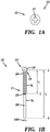
- Fig. 1A depicts a top plan view of a first surface 19 of a screw head 15 of a screw 10.
- the screw head 15 includes a driver slot 17.
- the screw 10 may be a round head 15 made of stainless steel, brass, nickel/sliver, carbon steel, titanium, or other appropriate metals or metal alloys.
- the driver slot 17 may be a single groove, a Phillips ® cross shaped groove, an hexagonal groove for turning with a hex wrench.
- Fig. 1B depicts a longitudinal cross-sectional view of the screw 10.
- the screw 10 comprises: the screw head 15, comprising: a first surface 19 having a driver slot 17 thereon, and a second surface 18, wherein the second surface 18 of the screw head 15 faces away from the first surface 19.
- the screw 10 comprises an elongated stem 11.
- the elongated stem 11 comprises a threaded first portion 20.
- a proximal end A of the threaded first portion 20 is mechanically and physically coupled to the second surface 18 of the screw head 15.
- the mechanical and physical coupling between the second surface 18 of the screw head 15 and the proximal end A of the threaded first portion 20 is not a breakaway 25, 43.
- the elongated stem 11 comprises a non-threaded second portion 30 extending from a distal end C of the threaded first portion 20; and a breakaway 25 therebetween.
- a “breakaway” is defined as a releasable coupling between a removable piece such as the proximal end 12 of the non-threaded second portion 20 and the distal end C of the threaded first portion 20.
- distal end is defined as the further point along the elongated stem 11 in reference to the second surface 18 of the screw head
- proximal is defined as the nearer point along the elongated stem 11 in reference to the second surface 18 of the screw head 15.
- releasably coupling is defined as forming or braking or cleaving or severing a mechanical and physical coupling between the removable piece such as the proximal end 12 of the non-threaded second portion 20 and the distal end C of the threaded first portion 20.
- screw 10, 13 into a screw hole 59, 100 or threaded hollow channel of a hinge 64
- screw 10, 13 is defined as engaging the threads 63 in the screw hole 59, 100 or hollow threaded channel 64 of a hinge 66, by rotating the screw 10, 13 about its longitudinal axis in a clockwise motion, resulting in the screw 10, 13 being essentially completely inserted into the screw hole 59, 100 or hollow threaded channel 64 of the hinge 66.
- Such engaging the threads 63 in the screw hole or hollow threaded channel 64 has the ultimate end that the screw 10, 13 has been essentially completely inserted into the screw hole 59, 100.
- the screw 10 comprises a non-threaded first portion 30 for making it easier to handle the screw 10. You insert the non-threaded first portion 30 of the screw 10 into a screw hole 100 first and then you are able to pull the threaded second portion 20 of the screw 10 into the screw hole 100 as the non-threaded second portion 30 is removed from the screw hole 100. This adapts the screw 10 to be more easily manipulated by hand by a user.
- a length L 1 from about 0.3375 in. to about 0.4125 in. (8.6-10.5 mm) may separate the proximal end A of the threaded first portion 20 and the distal end C of the threaded first portion 20.
- a length L 2 from about .6973 in. to about 0.8525 in. (18-21.7 mm) may separate the proximal end A of the threaded first portion 20 and the distal end B of the non-threaded second portion 30 of the elongated stem 11.
- a diameter W 3 of the non-threaded second portion is preferably smaller than a diameter W 2 of the threaded first portion 20 of the elongated stem 11.
- the diameter W 3 is from about 0.036 in. to about 0.044 in. (0.9-1.1 mm).
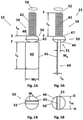
- Fig. 2A depicts a front longitudinal view of a screw 13.
- the screw 13 comprises: a screw head 50 and an elongated stem 14.
- the screw head 50 comprises: a first surface 44 having a driver slot 51 thereon.
- the screw head 50 comprises a second surface 48, depicted in Fig. 3A and described in associated text.
- the second surface 48 of the screw head 50 faces away from the first surface 44.
- the elongated stem 14, comprises: either a threaded first portion 20 and a non-threaded second portion 30 extending from the distal end C of the threaded first portion 20 and a first breakaway 25 therebetween, depicted in Fig.
- a threaded first portion 42 without the non-threaded second portion 30, depicted in Fig. 1B , extending from the threaded first portion 42 and a second breakaway 43.
- a proximal end E of the threaded first portion 42 is non-releasably coupled to the second surface 48 of the screw head 50.
- the mechanical and physical coupling between the second surface 48 of the screw head 50 and the proximal end E of the threaded first portion 42 is not a breakaway 25, 43.
- the first breakaway 25 releasably couples the non-threaded second portion 30 to the distal end C of the threaded first portion 20.
- the threaded first portion 20, without the non-threaded second portion 30 extends from the threaded first portion 20 and a second breakaway 43.
- a proximal end E of the threaded first portion 20 is non- releasably mechanically and physically coupled to the second surface 48 of the screw head 50.
- the mechanical and physical coupling between the second surface 48 of the screw head 50 and the proximal end E of the threaded first portion 20 is not a breakaway 25, 43.
- the second breakaway 43 releasably couples the first surface 48 of the screw head 50 to a breakaway tab 45.
- a screw 13 with a break away tab 45 on the screw head 50 guides screws 13 into a screw hole for easy maneuverability. Any size screw 13, or break away tab 45 may be placed anywhere on the head 50 of the screw 13. Insert the screw 13 in hole 59, turn the break away tab 45 to start the screwing operation and then break the break away tab 45 off.
- a length L 5 from the second surface 48 to the second breakaway 43, releasably coupling the breakaway tab 45 may be from about 0.1 in. to about 0.21 in. (2.5-5.3 mm).
- a width W 7 of the breakaway tab 45 may be from about 0.225 in. to about 0.275 in. (5.7-7 mm) and a length L 3 of the breakaway tab 45 may be from about 0.45 in. to about 0.55 in. (11.4-14 mm).
- Fig. 2B depicts a top plan view of a first surface 44 of a screw head 50 of the screw 13.
- the screw head 50 includes a driver slot 51.
- the screw 13 may be made of stainless steel, brass, nickel/sliver, carbon steel, titanium, or other appropriate metals or metal alloys.
- the driver slot 51 may be a single groove, a Phillips@ cross shaped groove, or an hexagonal groove for turning with a hex wrench.
- Fig. 3A depicts a side elevation view of the screw 13.
- a length L 4 from the proximal end E of the threaded first portion 20 to the distal end F of the threaded first portion of the elongated stem 14 may be from about 0.3942 in. to about 0.4818 in. (10-12.2 mm).
- a face 49 of the breakaway tab 45 and a longitudinal plane of the driver slot 51 are parallel.
- a width W 8 of the driver slot 51 may be from about 0.045 in. to about 0.055 in. (1.1-1.4 mm).
- a ratio of the thickness L 9 of the breakaway tab 45 of the screw 13 to the width W 8 of the driver slot 51 is from about 0.3:1.0 to about 0.4:0.9.
- a ratio of the length L 1 of the threaded first portion 20 to the non-threaded second portion 30 of the screw 10 is from about 1:1 to about 0.775:1.
- a diameter of the first breakaway 25 of the screw 10 is less than or equal to 0.015 in. (0.38mm), when the diameter of the elongated stem 11 is essentially equal to 0.040 in. (1 mm).
- a ratio of the width W 1 of the breakaway tab 45 to a length L 3 of the breakaway tab 45 is from about 1:2 to about 1:10.
- the screw head 50 is a slotted undercut oval countersunk head.
- the threaded first portion 42 has a 6-32 UNF thread, wherein conventional UNC or UNF thread is a 60 degree thread.
- a ratio of the length L 4 of the threaded first portion 42 to the length L 3 of the breakaway tab 45 of the screw 10 is from about 1:1 to about 0.876:1.
- Fig. 3B depicts a top plan view of a first surface 44 of a screw head 51 of the screw 50.
- a width W 1 of the second breakaway 43 across the first surface 44 of the screw head 50, depicted in Fig. 2B is from about 75% to about 95% of the length L 10 of the driver slot 51 thereon.
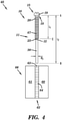
- Fig. 4 depicts a longitudinal cross-sectional view of a kit 65.
- the kit 65 comprises: a hinge 66, comprising first and second straps 60, 61, pivotably coupled to a cylinder 62.
- the cylinder 62 has a hollow threaded channel 64 therein.
- the kit 65 comprises: a screw 10, comprising: a head 19 and an elongated stem 11.
- the elongated stem 11 comprises: either a threaded first portion 20 adjacent to the head 15 and a non-threaded second portion 30 extending from the threaded first portion 20 and a first breakaway 25 therebetween.
- the first breakaway 25 releasably couples the threaded first portion 20 of the elongated stem 11 to the non-threaded second portion 30 of the elongated stem 11.
- the non-threaded second portion 30 of the elongated stem 11 has been aligned with the hollow threaded channel 64 in the hinge 66.
- the non-threaded second portion 30 of the elongated stem 11 has been inserted into the hollow threaded channel 64 in the hinge 66 so that the threaded first portion 20 of the elongated stem 11 catches at least one of the threads 63 of the hollow threaded channel 64 of the hinge 66.
- the kit 65 comprises; a screw 13, depicted in Figs 2A, 2B, and Figs. 3A, 3B .
- the screw 13 comprises: a screw head 50 and an elongated stem 14.
- the elongated stem 14 comprises a threaded first portion 42 physically and mechanically non-releasably coupled to the second surface 48 of the screw head 50 without the non-threaded second portion 30, depicted in Figs. 1A , B extending from the threaded first portion 42 and a second breakaway 43.
- the second breakaway 43 releasably couples the first surface 44 of the screw head 50 to a breakaway tab 45.
- the threaded first portion 42 of the elongated stem 11 has caught at least one thread 63 of the hollow threaded channel 64 of the hinge 66, by threading the threads 67 of the threaded first portion 20 of the elongated stem 11 with the threads 63 of the hollow threaded channel 64.
- proximal end E of the threaded first portion 42 and the second surface 48 of the screw head 50 are mechanically and physically non-releasably coupled.
- the breakaway tab 45 extends along a longitudinal axis of the screw 13, away from the first surface 44 of the screw head 50.
- Fig. 5 depicts a top plan view of a screw 85 having a screw head 86.
- the screw head 86 has a first surface 80 and a driver slot 81, therein.
- the screw head 86 is releasably coupled to a breakaway tab 84, having a breakaway 83 therebetween.
- the breakaway tab 84 has a first surface 79, and the first surface 79 may be coplanar with the first surface 80 of the screw head 86.
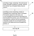
- Figs. 6A - 6C depict a flow diagram of a method 90 of replacing a screw 10, 13 in a hinge 66, depicted in Fig. 4 , and described in associated text and depicted in Figs. 2A.-3B , and described in associated text.
- a hinge 66 is provided in a step 92 of the method 90.
- first and second straps 60, 61 may be pivotably coupled to a cylinder 62.
- the cylinder 62 has a hollow threaded channel 64 therein;
- a screw 10, 13 is provided.
- the screw 10, 13 comprises: a head 15, 50; an elongated stem 11,14.
- the elongated stem 11, 14 comprises: either a threaded first portion 20, 42 adjacent to the head 15, 50; and a non-threaded second portion 30, extending from the threaded first portion 20, 42; and a first breakaway 25 therebetween, wherein the first breakaway 25 releasably couples the non-threaded second portion 30 to the distal end C of the threaded first portion 20, or a threaded first portion 42 adjacent to the head 50 without the non-threaded second portion 30 extending from the threaded first portion 42 and a second breakaway 43, wherein the second breakaway 43 releasably couples the first surface 44 of the screw head 50 to a breakaway tab 45;
- the non-threaded second portion 30 of the elongated stem 11 may be inserted into the hollow threaded channel 64 in the hinge 66 so that the non-threaded second portion 30 of the elongated stem 11 extends out of the hollow threaded channel 64 of the hinge 66.
- the threaded first portion 42 of the elongated stem 14 may be inserted into the hollow threaded channel 64 in the hinge 66 by a user manipulating the insertion using the breakaway tab 45.
- the threaded first portion 20, 42 of the elongated stem 11, 14 may be aligned with the threads 63 of the hollow threaded channel 64 of the hinge 66.
- the first threaded portion 20, 42 of the elongated stem 11, 14 may be screwed into the hollow threaded channel 64 of the hinge 66 by rotating the threaded first portion 20, 42 of the elongated stem 11, 14 that has been aligned with the threads 63 of the threaded hollow channel 64 of the hinge 66.
- the breakaway tab 45 extends along a longitudinal axis of the screw 13, away from the first surface 44 of the screw head 50.
- a first surface 79 of the breakaway tab 84 and a first surface 80 of the screw head 86 are coplanar, depicted in Fig. 5 , and described in associated text.
- a user may turn the breakaway tab 45 about its longitudinal axis to rotate the screw 13, wherein the breakaway tab 45 is releasably coupled to the first surface 44 of the screw head 50 by the second breakaway 43.
- the breakaway tab 45, 84 is broken off from the first surface 44 of the screw head 50 at the second breakaway 43, or at the second breakaway 83, after the threaded first portion 42 of the elongated stem 14 catches at least one thread 63 of the threaded hollow channel 64 of the hinge 66.
- the non-threaded second portion 30 of the elongated stem 11 is broken off at the first breakaway 25 from the threaded first portion 20 of the elongated stem 11 after the threaded first portion 20 of the elongated stem is essentially completely screwed into the threaded hollow channel 64 of the hinge 66.
- step 102 of the method 90 inserting the non-threaded second portion 30 of the elongated stem 11 into the hollow threaded channel 64 in the hinge 66 so that the non-threaded second portion 30 of the elongated stem 11 extends out of the hollow threaded channel 64 of the hinge 66, by a user pulling the non-threaded second portion 30 of the elongated stem 11.
- a user removes the non-threaded second portion 30 from the elongated stem 11 of the screw 10 after catching at least one thread 63 of the hollow threaded channel 64 of the hinge 66.
- the breakaway tab 45 extends along a longitudinal axis of the screw 13, away from the first surface 44 of the screw head 50 when the breakaway tab 45 is broken off from the first surface 44 of the screw head 50 at the second breakaway 43, after the threaded first portion 42 of the elongated stem 14 catches at least one thread 63 of the threaded hollow channel 64 of the hinge 66.
Landscapes
- Engineering & Computer Science (AREA)
- Mechanical Engineering (AREA)
- General Engineering & Computer Science (AREA)
- Surgical Instruments (AREA)
- Hand Tools For Fitting Together And Separating, Or Other Hand Tools (AREA)
- Eyeglasses (AREA)
- Pivots And Pivotal Connections (AREA)
- Dowels (AREA)
- Mutual Connection Of Rods And Tubes (AREA)
- Prostheses (AREA)
- Connection Of Plates (AREA)
- Food-Manufacturing Devices (AREA)
- Hinges (AREA)
Applications Claiming Priority (4)
| Application Number | Priority Date | Filing Date | Title |
|---|---|---|---|
| US96351907P | 2007-08-06 | 2007-08-06 | |
| US99372607P | 2007-09-14 | 2007-09-14 | |
| EP08782656.6A EP2174023B2 (en) | 2007-08-06 | 2008-08-06 | Screw with breakaway and methods of using the same |
| PCT/US2008/072386 WO2009021073A2 (en) | 2007-08-06 | 2008-08-06 | Screw with breakaway and methods of using the same |
Related Parent Applications (2)
| Application Number | Title | Priority Date | Filing Date |
|---|---|---|---|
| EP08782656.6A Division EP2174023B2 (en) | 2007-08-06 | 2008-08-06 | Screw with breakaway and methods of using the same |
| EP08782656.6A Division-Into EP2174023B2 (en) | 2007-08-06 | 2008-08-06 | Screw with breakaway and methods of using the same |
Publications (2)
| Publication Number | Publication Date |
|---|---|
| EP2843247A1 EP2843247A1 (en) | 2015-03-04 |
| EP2843247B1 true EP2843247B1 (en) | 2022-02-16 |
Family
ID=40342027
Family Applications (2)
| Application Number | Title | Priority Date | Filing Date |
|---|---|---|---|
| EP14190623.0A Active EP2843247B1 (en) | 2007-08-06 | 2008-08-06 | Screw with breakaway and methods of using same |
| EP08782656.6A Active EP2174023B2 (en) | 2007-08-06 | 2008-08-06 | Screw with breakaway and methods of using the same |
Family Applications After (1)
| Application Number | Title | Priority Date | Filing Date |
|---|---|---|---|
| EP08782656.6A Active EP2174023B2 (en) | 2007-08-06 | 2008-08-06 | Screw with breakaway and methods of using the same |
Country Status (12)
| Country | Link |
|---|---|
| US (4) | US8070403B2 (enExample) |
| EP (2) | EP2843247B1 (enExample) |
| JP (2) | JP2010535993A (enExample) |
| KR (3) | KR20160038085A (enExample) |
| CN (1) | CN101815877B (enExample) |
| AU (1) | AU2008283850B2 (enExample) |
| BR (1) | BRPI0814837A2 (enExample) |
| CA (1) | CA2695751C (enExample) |
| ES (2) | ES2528121T5 (enExample) |
| RU (1) | RU2493446C2 (enExample) |
| WO (1) | WO2009021073A2 (enExample) |
| ZA (1) | ZA201003664B (enExample) |
Families Citing this family (12)
| Publication number | Priority date | Publication date | Assignee | Title |
|---|---|---|---|---|
| US8556556B2 (en) * | 2007-08-06 | 2013-10-15 | Fbb Asset Management Limited Partnership | Screw with breakaway and methods of using the same |
| WO2009021073A2 (en) * | 2007-08-06 | 2009-02-12 | Nancy Tedeschi | Screw with breakaway and methods of using the same |
| DE102010042260A1 (de) * | 2010-10-11 | 2012-04-12 | Hilti Aktiengesellschaft | Verfahren zur Herstellung von drehmomentbegrenzten Befestigungsvorrichtungen |
| US8845255B2 (en) | 2011-09-29 | 2014-09-30 | Jordan Creativeworks, Llc | Guide apparatuses for use with fasteners |
| US9907576B2 (en) * | 2011-10-05 | 2018-03-06 | The University Of Akron | Reduced shock breakaway set screw for use with a surgical construct |
| CN103437429B (zh) * | 2013-07-18 | 2016-04-20 | 浙江中隧桥波形钢腹板有限公司 | 波形钢板与平钢板栓接构件及制造工艺 |
| CN105793912B (zh) * | 2013-12-02 | 2017-08-29 | 蛇牌股份公司 | 用于医疗无菌容器的安全密封件 |
| US11058469B2 (en) * | 2013-12-13 | 2021-07-13 | The University Of Akron | Minimal shock set screw |
| US9458610B2 (en) * | 2014-06-10 | 2016-10-04 | Homewerks Worldwide, LLC | Plumbing connector |
| KR102046696B1 (ko) * | 2017-11-24 | 2019-11-21 | 대모 엔지니어링 주식회사 | 핀 고정 장치 |
| RU183253U1 (ru) * | 2018-04-17 | 2018-09-14 | Компания Домидо Лимитед | Соединительное устройство с отрывной головкой |
| AU2022331227A1 (en) * | 2021-08-15 | 2024-02-08 | Cloozz Ltd | Handle extension to aid threading a button through a hole |
Family Cites Families (89)
| Publication number | Priority date | Publication date | Assignee | Title |
|---|---|---|---|---|
| US869443A (en) * | 1907-03-26 | 1907-10-29 | Jens Gabriel Fredrik Lund | Screw-spanner. |
| US933831A (en) * | 1908-08-05 | 1909-09-14 | Joseph L De Steiger | Machine-screw. |
| US1039576A (en) * | 1910-06-28 | 1912-09-24 | Mueller Mfg Co H | Seal for pipe-couplings. |
| US1541518A (en) | 1925-02-16 | 1925-06-09 | Paul H Mccain | Thumb or wing screw |
| US1662834A (en) | 1927-04-09 | 1928-03-20 | Daniel I Reiter | Fastening device |
| US1970071A (en) * | 1933-09-06 | 1934-08-14 | Carl O Bengtsson | Nonremovable display device |
| US2177978A (en) | 1938-03-31 | 1939-10-31 | Darvie Bernard | Ornamental indicator |
| BE468603A (enExample) * | 1939-11-28 | |||
| US2230984A (en) | 1940-12-06 | 1941-02-04 | Chernow Michael | Clip |
| US2382019A (en) * | 1944-05-02 | 1945-08-14 | Miller Edwin August | Compound screw |
| US2408559A (en) * | 1945-06-19 | 1946-10-01 | Cherry Rivet Company | Self-setting tubular rivet |
| US2542340A (en) * | 1947-09-11 | 1951-02-20 | Mauraton Louis | Hinge |
| US2552265A (en) | 1949-06-02 | 1951-05-08 | Robert H Edwards | Novelty ornament |
| US2636194A (en) * | 1949-07-23 | 1953-04-28 | Eaton Mfg Co | Method of making self-locking screws |
| FR1120162A (fr) * | 1955-01-18 | 1956-07-02 | Paumelle à fiche démontable | |
| US2991695A (en) * | 1958-02-12 | 1961-07-11 | Harold V Jones | Eyeglass frame assembly with expandible locking screw |
| US3208328A (en) * | 1962-04-11 | 1965-09-28 | John L Myers | Screws |
| US3307444A (en) * | 1965-06-21 | 1967-03-07 | Nat Screw & Mfg Company | Blind fastener |
| US3343443A (en) * | 1965-10-21 | 1967-09-26 | Anthony W Moore | Blind rivet assembly |
| US3444775A (en) * | 1968-02-16 | 1969-05-20 | Lockheed Aircraft Corp | Nut formed with multiple torque-off collars |
| IT987348B (it) * | 1973-05-11 | 1975-02-20 | Mazzucconi Vittorio | Telaio per la composizione di mobili formato da tubo bicilindrico e giunto universale |
| US3968661A (en) | 1974-09-23 | 1976-07-13 | Carl-Art, Inc. | Jewelry having rotatable indicia-bearing disc and indicating means |
| US3941027A (en) * | 1975-05-08 | 1976-03-02 | Lockheed Aircraft Corporation | Fastener system for structural members |
| JPS5342125Y2 (enExample) * | 1975-07-17 | 1978-10-11 | ||
| US4112811A (en) * | 1977-04-15 | 1978-09-12 | John Olmsted King | Self-dimpling fastener pin |
| JPS5592288U (enExample) | 1978-12-20 | 1980-06-26 | ||
| US4345848A (en) | 1979-11-27 | 1982-08-24 | Stephen Cheselka | Spectacle hinge pin |
| JPS5716012U (enExample) * | 1980-06-30 | 1982-01-27 | ||
| JPS57164318U (enExample) * | 1981-04-09 | 1982-10-16 | ||
| US4492900A (en) | 1981-12-14 | 1985-01-08 | Rca Corporation | Single controllable switch, push-pull inverter for a television receiver ferroresonant power supply |
| US4519736A (en) * | 1982-05-07 | 1985-05-28 | Sigmund Jerry A | Pin type fastener usable with swage collar to form a joint |
| US4492500A (en) * | 1983-02-10 | 1985-01-08 | Ewing Peter D | Torque limiting set screw |
| JPS59141324U (ja) * | 1983-03-11 | 1984-09-21 | 株式会社三工光学 | 眼鏡の蝶番のねじ機構 |
| EP0120664B1 (en) | 1983-03-30 | 1987-05-06 | The Secretary of State for Defence in Her Britannic Majesty's Government of the United Kingdom of Great Britain and | Track link adhesion pad assembly |
| JPS61129243A (ja) * | 1984-11-29 | 1986-06-17 | Nippon Steel Corp | 予備締め可能なトルシア形ボルト |
| US4867625A (en) * | 1985-04-29 | 1989-09-19 | Huck Manufacturing Company | Variable clamp fastener and method |
| US4838746A (en) * | 1988-01-12 | 1989-06-13 | Grumman Aerospace Corporation | Break-away rivet configuration |
| FR2658570B1 (fr) * | 1990-02-21 | 1992-04-30 | Chevassus | Vis prolongee d'une partie tronconique. |
| JPH049015U (enExample) | 1990-05-09 | 1992-01-27 | ||
| US5077931A (en) | 1990-06-04 | 1992-01-07 | Marshall Earl C | Fishing lure |
| JPH0446420A (ja) | 1990-06-14 | 1992-02-17 | Shiyoudenriyoku Kosoku Tsushin Kenkyusho:Kk | エリア通信方式 |
| US5195859A (en) * | 1990-08-20 | 1993-03-23 | The Glasscrew Company | Fastener for joining a plurality of layers |
| JPH0446420U (enExample) | 1990-08-23 | 1992-04-20 | ||
| JPH04101010U (ja) * | 1991-02-05 | 1992-09-01 | 株式会社村井 | ねじ及び眼鏡枠用ねじ |
| US5893538A (en) * | 1991-09-13 | 1999-04-13 | Onishi; Yoshio | Conduit clamp |
| FR2685570A1 (fr) | 1991-12-20 | 1993-06-25 | Valeo Systemes Dessuyage | Rotor dote de moyens de fixation des tuiles servant d'aimants permanents, et machine magneto-dynamique, comme un moteur sans collecteur, ainsi equipee. |
| US5379505A (en) * | 1993-06-16 | 1995-01-10 | Lock-N-Stitch International | Method for repairing cracks |
| US5415507A (en) * | 1993-07-29 | 1995-05-16 | Elco Industries, Inc. | Anchor with adjustable seal |
| GB2285106B (en) * | 1993-12-23 | 1997-07-16 | Titus Int Ltd | Joint forming device |
| JP2975261B2 (ja) * | 1994-05-26 | 1999-11-10 | 日野自動車工業株式会社 | 車両の部品取付用部材 |
| US5685714A (en) | 1994-06-16 | 1997-11-11 | Implant Innovations, Inc. | Support post for use in dental implant system |
| FR2721819B1 (fr) * | 1994-07-04 | 1996-10-04 | Amp Dev | Dispositif de cheville auto-foreuse et auto-taraudeuse, a embout de maintien secable, pour le blocage d'une plaque d'osteosynthese ou la coaptation de deux fragments osseux |
| US5615850A (en) | 1995-03-06 | 1997-04-01 | Cloninger; Leonard W. | Wire support bracket |
| US5746556A (en) | 1995-03-13 | 1998-05-05 | Kabushiki Kaisha Youma Kohboh | Anchor unit with expansive anchor member expanded by utilizing turning force of bolt |
| US5746096A (en) * | 1995-06-26 | 1998-05-05 | Textron Inc. | Break-off drillpoint screw |
| JPH0932210A (ja) * | 1995-07-17 | 1997-02-04 | Miyagawa Kogyo Kk | ボルト、屋根材の取り付け方法及び壁材の取り付け方法 |
| US5699140A (en) | 1996-02-02 | 1997-12-16 | Fuhrman; Esther | Jewelry eyeglass holder |
| US6520635B1 (en) | 1996-04-08 | 2003-02-18 | Patricia M. Ignatowski | Ornamental eyewear |
| US5675988A (en) | 1996-04-08 | 1997-10-14 | Ignatowski; Patricia M. | Jewelry article adapted for extension from eyeglasses |
| US5682646A (en) * | 1996-05-13 | 1997-11-04 | Chrysler Corporation | Threaded removable vehicle door hinge pin |
| US5651652A (en) | 1996-09-19 | 1997-07-29 | Williams; David J. | Breakaway tamperproof fastener |
| US5697743A (en) * | 1996-10-04 | 1997-12-16 | Parker; Stanley F. | Tamper proof threaded fastener |
| AUPO502997A0 (en) * | 1997-02-11 | 1997-03-06 | W.A. Deutscher Pty Ltd | Fastening screw and fastening system |
| US5906029A (en) | 1997-03-25 | 1999-05-25 | Fox; Larry | Hinge repair kit and installation method |
| US5863168A (en) | 1997-07-31 | 1999-01-26 | Demaray; Eric Paul | Washer with a detachable extension |
| US5896184A (en) | 1997-08-01 | 1999-04-20 | Lowe; Laura Lynn | Temple ornamentation for eye glasses |
| CA2228539C (en) * | 1998-02-03 | 2003-11-18 | Rudolf Gruber | Improved hinge with removable pin |
| JPH11334502A (ja) * | 1998-05-28 | 1999-12-07 | Toyota Auto Body Co Ltd | 車両用バンパーの取付け構造 |
| US6077012A (en) * | 1998-12-01 | 2000-06-20 | Huck International Inc. | Self-retaining fastener |
| JP2000240628A (ja) | 1999-02-24 | 2000-09-05 | Kazuyuki Sano | 調心ボルト |
| DE19916206A1 (de) * | 1999-04-10 | 2000-06-15 | Daimler Chrysler Ag | Schraube mit einer Einschraubspitze |
| US20010048860A1 (en) | 2000-06-06 | 2001-12-06 | Ross Harold D. | Tethered screw |
| US6454768B1 (en) * | 2000-12-05 | 2002-09-24 | Roger P. Jackson | Removable gripping set screw |
| CA2348323C (en) * | 2001-05-24 | 2006-02-14 | Multimatic Inc. | Automotive door hinge with removable component adapted for structural reassembly |
| US6793208B1 (en) | 2001-11-09 | 2004-09-21 | Charles W. Riddle, Jr. | Tool system for repairing eyeglasses |
| US6665922B2 (en) * | 2002-05-13 | 2003-12-23 | Hi-Shear Corporation | Pull stem hi-lite pin with pull groove for swaging collars |
| DE10258149B4 (de) * | 2002-12-10 | 2006-04-06 | Kamax-Werke Rudolf Kellermann Gmbh & Co. Kg | Presspassverbindungselement und Verfahren zu dessen Herstellung |
| ES2281620T3 (es) * | 2003-02-12 | 2007-10-01 | Synthes Gmbh | Tornillo que comprende un destornillador integrado. |
| US7059032B2 (en) * | 2003-06-04 | 2006-06-13 | Ronald F Lehner | Door hinge repair apparatus and method |
| US20050115046A1 (en) * | 2003-12-02 | 2005-06-02 | Woods Mark A. | Methods and systems for fastening components, including composite aircraft panels |
| JP4550052B2 (ja) | 2004-06-10 | 2010-09-22 | 日本電信電話株式会社 | ネジ |
| US6863394B1 (en) | 2004-06-14 | 2005-03-08 | Glendia Nelson | Ornamental attachment for a pair of eyeglasses |
| WO2006039412A2 (en) * | 2004-09-29 | 2006-04-13 | Trufast Corporation | Fastener having a removable drill tip and method |
| US8142126B2 (en) * | 2005-09-02 | 2012-03-27 | The Boeing Company | Multi-piece fastener with self-indexing nut |
| DE202006013551U1 (de) * | 2006-09-01 | 2006-11-02 | Kienle Ltd. & Co. Kg | Winkelverbinder zur Verbindung von flächenförmigen Abtrennungselementen |
| US7987637B2 (en) * | 2006-09-25 | 2011-08-02 | Smith Patrick J | Adjustable shim |
| US8556556B2 (en) * | 2007-08-06 | 2013-10-15 | Fbb Asset Management Limited Partnership | Screw with breakaway and methods of using the same |
| WO2009021073A2 (en) * | 2007-08-06 | 2009-02-12 | Nancy Tedeschi | Screw with breakaway and methods of using the same |
| US8197512B1 (en) * | 2008-07-16 | 2012-06-12 | Zimmer Spine, Inc. | System and method for spine stabilization using resilient inserts |
-
2008
- 2008-08-06 WO PCT/US2008/072386 patent/WO2009021073A2/en not_active Ceased
- 2008-08-06 RU RU2010107894/12A patent/RU2493446C2/ru not_active IP Right Cessation
- 2008-08-06 KR KR1020167008198A patent/KR20160038085A/ko not_active Ceased
- 2008-08-06 KR KR1020107004619A patent/KR20100065311A/ko not_active Ceased
- 2008-08-06 ES ES08782656T patent/ES2528121T5/es active Active
- 2008-08-06 KR KR1020177017652A patent/KR20170078859A/ko not_active Ceased
- 2008-08-06 CA CA2695751A patent/CA2695751C/en active Active
- 2008-08-06 CN CN2008801021332A patent/CN101815877B/zh active Active
- 2008-08-06 EP EP14190623.0A patent/EP2843247B1/en active Active
- 2008-08-06 US US12/187,254 patent/US8070403B2/en active Active - Reinstated
- 2008-08-06 BR BRPI0814837A patent/BRPI0814837A2/pt active Search and Examination
- 2008-08-06 ES ES14190623T patent/ES2913206T3/es active Active
- 2008-08-06 JP JP2010520292A patent/JP2010535993A/ja active Pending
- 2008-08-06 EP EP08782656.6A patent/EP2174023B2/en active Active
- 2008-08-06 AU AU2008283850A patent/AU2008283850B2/en active Active
-
2010
- 2010-05-24 ZA ZA2010/03664A patent/ZA201003664B/en unknown
-
2011
- 2011-02-05 US US13/021,747 patent/US8375546B2/en active Active
- 2011-02-18 US US13/030,377 patent/US8997327B2/en active Active
-
2013
- 2013-01-04 US US13/734,806 patent/US9493972B2/en active Active
- 2013-12-27 JP JP2013272255A patent/JP5806285B2/ja active Active
Also Published As
Similar Documents
| Publication | Publication Date | Title |
|---|---|---|
| EP2843247B1 (en) | Screw with breakaway and methods of using same | |
| US8556556B2 (en) | Screw with breakaway and methods of using the same | |
| JP2010535993A5 (enExample) | ||
| TW201413124A (zh) | 平頭螺絲 | |
| US20160121469A1 (en) | Nut Driving Cleaning System | |
| US7954941B2 (en) | Coupling device with breakaway and methods of using the same | |
| AU2011101044A4 (en) | Screw with breakaway and methods of using the same | |
| HK1147791B (en) | Screw with breakaway and methods of using the same | |
| CN201621167U (zh) | 具有可拆卸尾部的螺套 | |
| CA2616478A1 (en) | Fastener with removable element | |
| MXPA99008370A (en) | Threaded insert that has a removed tongue |
Legal Events
| Date | Code | Title | Description |
|---|---|---|---|
| 17P | Request for examination filed |
Effective date: 20141028 |
|
| AC | Divisional application: reference to earlier application |
Ref document number: 2174023 Country of ref document: EP Kind code of ref document: P |
|
| AK | Designated contracting states |
Kind code of ref document: A1 Designated state(s): AT BE BG CH CY CZ DE DK EE ES FI FR GB GR HR HU IE IS IT LI LT LU LV MC MT NL NO PL PT RO SE SI SK TR |
|
| PUAI | Public reference made under article 153(3) epc to a published international application that has entered the european phase |
Free format text: ORIGINAL CODE: 0009012 |
|
| R17P | Request for examination filed (corrected) |
Effective date: 20150904 |
|
| RBV | Designated contracting states (corrected) |
Designated state(s): AT BE BG CH CY CZ DE DK EE ES FI FR GB GR HR HU IE IS IT LI LT LU LV MC MT NL NO PL PT RO SE SI SK TR |
|
| 17Q | First examination report despatched |
Effective date: 20161017 |
|
| STAA | Information on the status of an ep patent application or granted ep patent |
Free format text: STATUS: EXAMINATION IS IN PROGRESS |
|
| GRAP | Despatch of communication of intention to grant a patent |
Free format text: ORIGINAL CODE: EPIDOSNIGR1 |
|
| STAA | Information on the status of an ep patent application or granted ep patent |
Free format text: STATUS: GRANT OF PATENT IS INTENDED |
|
| RIC1 | Information provided on ipc code assigned before grant |
Ipc: F16B 35/04 20060101ALN20211102BHEP Ipc: E05D 3/02 20060101ALI20211102BHEP Ipc: E05D 5/12 20060101ALI20211102BHEP Ipc: F16B 31/02 20060101ALI20211102BHEP Ipc: F16B 23/00 20060101AFI20211102BHEP |
|
| INTG | Intention to grant announced |
Effective date: 20211208 |
|
| GRAS | Grant fee paid |
Free format text: ORIGINAL CODE: EPIDOSNIGR3 |
|
| GRAA | (expected) grant |
Free format text: ORIGINAL CODE: 0009210 |
|
| STAA | Information on the status of an ep patent application or granted ep patent |
Free format text: STATUS: THE PATENT HAS BEEN GRANTED |
|
| AC | Divisional application: reference to earlier application |
Ref document number: 2174023 Country of ref document: EP Kind code of ref document: P |
|
| AK | Designated contracting states |
Kind code of ref document: B1 Designated state(s): AT BE BG CH CY CZ DE DK EE ES FI FR GB GR HR HU IE IS IT LI LT LU LV MC MT NL NO PL PT RO SE SI SK TR |
|
| REG | Reference to a national code |
Ref country code: GB Ref legal event code: FG4D |
|
| REG | Reference to a national code |
Ref country code: CH Ref legal event code: EP |
|
| REG | Reference to a national code |
Ref country code: DE Ref legal event code: R096 Ref document number: 602008064398 Country of ref document: DE |
|
| REG | Reference to a national code |
Ref country code: AT Ref legal event code: REF Ref document number: 1469052 Country of ref document: AT Kind code of ref document: T Effective date: 20220315 |
|
| REG | Reference to a national code |
Ref country code: IE Ref legal event code: FG4D |
|
| REG | Reference to a national code |
Ref country code: ES Ref legal event code: FG2A Ref document number: 2913206 Country of ref document: ES Kind code of ref document: T3 Effective date: 20220601 |
|
| REG | Reference to a national code |
Ref country code: LT Ref legal event code: MG9D |
|
| REG | Reference to a national code |
Ref country code: NL Ref legal event code: MP Effective date: 20220216 |
|
| REG | Reference to a national code |
Ref country code: AT Ref legal event code: MK05 Ref document number: 1469052 Country of ref document: AT Kind code of ref document: T Effective date: 20220216 |
|
| PG25 | Lapsed in a contracting state [announced via postgrant information from national office to epo] |
Ref country code: SE Free format text: LAPSE BECAUSE OF FAILURE TO SUBMIT A TRANSLATION OF THE DESCRIPTION OR TO PAY THE FEE WITHIN THE PRESCRIBED TIME-LIMIT Effective date: 20220216 Ref country code: PT Free format text: LAPSE BECAUSE OF FAILURE TO SUBMIT A TRANSLATION OF THE DESCRIPTION OR TO PAY THE FEE WITHIN THE PRESCRIBED TIME-LIMIT Effective date: 20220616 Ref country code: NO Free format text: LAPSE BECAUSE OF FAILURE TO SUBMIT A TRANSLATION OF THE DESCRIPTION OR TO PAY THE FEE WITHIN THE PRESCRIBED TIME-LIMIT Effective date: 20220516 Ref country code: NL Free format text: LAPSE BECAUSE OF FAILURE TO SUBMIT A TRANSLATION OF THE DESCRIPTION OR TO PAY THE FEE WITHIN THE PRESCRIBED TIME-LIMIT Effective date: 20220216 Ref country code: LT Free format text: LAPSE BECAUSE OF FAILURE TO SUBMIT A TRANSLATION OF THE DESCRIPTION OR TO PAY THE FEE WITHIN THE PRESCRIBED TIME-LIMIT Effective date: 20220216 Ref country code: HR Free format text: LAPSE BECAUSE OF FAILURE TO SUBMIT A TRANSLATION OF THE DESCRIPTION OR TO PAY THE FEE WITHIN THE PRESCRIBED TIME-LIMIT Effective date: 20220216 Ref country code: BG Free format text: LAPSE BECAUSE OF FAILURE TO SUBMIT A TRANSLATION OF THE DESCRIPTION OR TO PAY THE FEE WITHIN THE PRESCRIBED TIME-LIMIT Effective date: 20220516 |
|
| PG25 | Lapsed in a contracting state [announced via postgrant information from national office to epo] |
Ref country code: PL Free format text: LAPSE BECAUSE OF FAILURE TO SUBMIT A TRANSLATION OF THE DESCRIPTION OR TO PAY THE FEE WITHIN THE PRESCRIBED TIME-LIMIT Effective date: 20220216 Ref country code: LV Free format text: LAPSE BECAUSE OF FAILURE TO SUBMIT A TRANSLATION OF THE DESCRIPTION OR TO PAY THE FEE WITHIN THE PRESCRIBED TIME-LIMIT Effective date: 20220216 Ref country code: GR Free format text: LAPSE BECAUSE OF FAILURE TO SUBMIT A TRANSLATION OF THE DESCRIPTION OR TO PAY THE FEE WITHIN THE PRESCRIBED TIME-LIMIT Effective date: 20220517 Ref country code: FI Free format text: LAPSE BECAUSE OF FAILURE TO SUBMIT A TRANSLATION OF THE DESCRIPTION OR TO PAY THE FEE WITHIN THE PRESCRIBED TIME-LIMIT Effective date: 20220216 Ref country code: AT Free format text: LAPSE BECAUSE OF FAILURE TO SUBMIT A TRANSLATION OF THE DESCRIPTION OR TO PAY THE FEE WITHIN THE PRESCRIBED TIME-LIMIT Effective date: 20220216 |
|
| PG25 | Lapsed in a contracting state [announced via postgrant information from national office to epo] |
Ref country code: IS Free format text: LAPSE BECAUSE OF FAILURE TO SUBMIT A TRANSLATION OF THE DESCRIPTION OR TO PAY THE FEE WITHIN THE PRESCRIBED TIME-LIMIT Effective date: 20220616 |
|
| PG25 | Lapsed in a contracting state [announced via postgrant information from national office to epo] |
Ref country code: SK Free format text: LAPSE BECAUSE OF FAILURE TO SUBMIT A TRANSLATION OF THE DESCRIPTION OR TO PAY THE FEE WITHIN THE PRESCRIBED TIME-LIMIT Effective date: 20220216 Ref country code: RO Free format text: LAPSE BECAUSE OF FAILURE TO SUBMIT A TRANSLATION OF THE DESCRIPTION OR TO PAY THE FEE WITHIN THE PRESCRIBED TIME-LIMIT Effective date: 20220216 Ref country code: EE Free format text: LAPSE BECAUSE OF FAILURE TO SUBMIT A TRANSLATION OF THE DESCRIPTION OR TO PAY THE FEE WITHIN THE PRESCRIBED TIME-LIMIT Effective date: 20220216 Ref country code: DK Free format text: LAPSE BECAUSE OF FAILURE TO SUBMIT A TRANSLATION OF THE DESCRIPTION OR TO PAY THE FEE WITHIN THE PRESCRIBED TIME-LIMIT Effective date: 20220216 Ref country code: CZ Free format text: LAPSE BECAUSE OF FAILURE TO SUBMIT A TRANSLATION OF THE DESCRIPTION OR TO PAY THE FEE WITHIN THE PRESCRIBED TIME-LIMIT Effective date: 20220216 |
|
| REG | Reference to a national code |
Ref country code: DE Ref legal event code: R097 Ref document number: 602008064398 Country of ref document: DE |
|
| PLBE | No opposition filed within time limit |
Free format text: ORIGINAL CODE: 0009261 |
|
| STAA | Information on the status of an ep patent application or granted ep patent |
Free format text: STATUS: NO OPPOSITION FILED WITHIN TIME LIMIT |
|
| 26N | No opposition filed |
Effective date: 20221117 |
|
| PG25 | Lapsed in a contracting state [announced via postgrant information from national office to epo] |
Ref country code: SI Free format text: LAPSE BECAUSE OF FAILURE TO SUBMIT A TRANSLATION OF THE DESCRIPTION OR TO PAY THE FEE WITHIN THE PRESCRIBED TIME-LIMIT Effective date: 20220216 |
|
| PG25 | Lapsed in a contracting state [announced via postgrant information from national office to epo] |
Ref country code: MC Free format text: LAPSE BECAUSE OF FAILURE TO SUBMIT A TRANSLATION OF THE DESCRIPTION OR TO PAY THE FEE WITHIN THE PRESCRIBED TIME-LIMIT Effective date: 20220216 |
|
| REG | Reference to a national code |
Ref country code: CH Ref legal event code: PL |
|
| PG25 | Lapsed in a contracting state [announced via postgrant information from national office to epo] |
Ref country code: LU Free format text: LAPSE BECAUSE OF NON-PAYMENT OF DUE FEES Effective date: 20220806 Ref country code: LI Free format text: LAPSE BECAUSE OF NON-PAYMENT OF DUE FEES Effective date: 20220831 Ref country code: CH Free format text: LAPSE BECAUSE OF NON-PAYMENT OF DUE FEES Effective date: 20220831 |
|
| PG25 | Lapsed in a contracting state [announced via postgrant information from national office to epo] |
Ref country code: IE Free format text: LAPSE BECAUSE OF NON-PAYMENT OF DUE FEES Effective date: 20220806 |
|
| PG25 | Lapsed in a contracting state [announced via postgrant information from national office to epo] |
Ref country code: HU Free format text: LAPSE BECAUSE OF FAILURE TO SUBMIT A TRANSLATION OF THE DESCRIPTION OR TO PAY THE FEE WITHIN THE PRESCRIBED TIME-LIMIT; INVALID AB INITIO Effective date: 20080806 |
|
| PG25 | Lapsed in a contracting state [announced via postgrant information from national office to epo] |
Ref country code: CY Free format text: LAPSE BECAUSE OF FAILURE TO SUBMIT A TRANSLATION OF THE DESCRIPTION OR TO PAY THE FEE WITHIN THE PRESCRIBED TIME-LIMIT Effective date: 20220216 |
|
| PG25 | Lapsed in a contracting state [announced via postgrant information from national office to epo] |
Ref country code: MT Free format text: LAPSE BECAUSE OF FAILURE TO SUBMIT A TRANSLATION OF THE DESCRIPTION OR TO PAY THE FEE WITHIN THE PRESCRIBED TIME-LIMIT Effective date: 20220216 |
|
| PGFP | Annual fee paid to national office [announced via postgrant information from national office to epo] |
Ref country code: ES Payment date: 20250902 Year of fee payment: 18 |
|
| PGFP | Annual fee paid to national office [announced via postgrant information from national office to epo] |
Ref country code: DE Payment date: 20250822 Year of fee payment: 18 |
|
| PGFP | Annual fee paid to national office [announced via postgrant information from national office to epo] |
Ref country code: IT Payment date: 20250826 Year of fee payment: 18 |
|
| PGFP | Annual fee paid to national office [announced via postgrant information from national office to epo] |
Ref country code: BE Payment date: 20250825 Year of fee payment: 18 Ref country code: GB Payment date: 20250824 Year of fee payment: 18 |
|
| PGFP | Annual fee paid to national office [announced via postgrant information from national office to epo] |
Ref country code: FR Payment date: 20250825 Year of fee payment: 18 |
|
| PG25 | Lapsed in a contracting state [announced via postgrant information from national office to epo] |
Ref country code: TR Free format text: LAPSE BECAUSE OF FAILURE TO SUBMIT A TRANSLATION OF THE DESCRIPTION OR TO PAY THE FEE WITHIN THE PRESCRIBED TIME-LIMIT Effective date: 20220216 |