EP2843105B1 - Ensemble de porte pour dispositif de traitement du linge et procédé de fonctionnement - Google Patents
Ensemble de porte pour dispositif de traitement du linge et procédé de fonctionnement Download PDFInfo
- Publication number
- EP2843105B1 EP2843105B1 EP13182520.0A EP13182520A EP2843105B1 EP 2843105 B1 EP2843105 B1 EP 2843105B1 EP 13182520 A EP13182520 A EP 13182520A EP 2843105 B1 EP2843105 B1 EP 2843105B1
- Authority
- EP
- European Patent Office
- Prior art keywords
- handle
- plane
- door assembly
- frame
- door
- Prior art date
- Legal status (The legal status is an assumption and is not a legal conclusion. Google has not performed a legal analysis and makes no representation as to the accuracy of the status listed.)
- Active
Links
- 238000000034 method Methods 0.000 title claims description 14
- 230000007246 mechanism Effects 0.000 claims description 20
- 230000008878 coupling Effects 0.000 description 93
- 238000010168 coupling process Methods 0.000 description 93
- 238000005859 coupling reaction Methods 0.000 description 93
- 239000011521 glass Substances 0.000 description 31
- 230000008859 change Effects 0.000 description 22
- 238000005406 washing Methods 0.000 description 22
- NJPPVKZQTLUDBO-UHFFFAOYSA-N novaluron Chemical compound C1=C(Cl)C(OC(F)(F)C(OC(F)(F)F)F)=CC=C1NC(=O)NC(=O)C1=C(F)C=CC=C1F NJPPVKZQTLUDBO-UHFFFAOYSA-N 0.000 description 12
- 239000000463 material Substances 0.000 description 11
- 238000004519 manufacturing process Methods 0.000 description 6
- 238000001035 drying Methods 0.000 description 5
- 230000002441 reversible effect Effects 0.000 description 4
- XLYOFNOQVPJJNP-UHFFFAOYSA-N water Substances O XLYOFNOQVPJJNP-UHFFFAOYSA-N 0.000 description 4
- 230000000712 assembly Effects 0.000 description 3
- 238000000429 assembly Methods 0.000 description 3
- 238000003780 insertion Methods 0.000 description 3
- 230000037431 insertion Effects 0.000 description 3
- 239000002184 metal Substances 0.000 description 3
- 229910052751 metal Inorganic materials 0.000 description 3
- 230000001681 protective effect Effects 0.000 description 3
- 238000010276 construction Methods 0.000 description 2
- 230000006378 damage Effects 0.000 description 2
- 230000004048 modification Effects 0.000 description 2
- 238000012986 modification Methods 0.000 description 2
- 230000008569 process Effects 0.000 description 2
- 229910001220 stainless steel Inorganic materials 0.000 description 2
- 239000010935 stainless steel Substances 0.000 description 2
- 238000005728 strengthening Methods 0.000 description 2
- 238000013519 translation Methods 0.000 description 2
- 230000009471 action Effects 0.000 description 1
- 239000011248 coating agent Substances 0.000 description 1
- 238000000576 coating method Methods 0.000 description 1
- 230000007797 corrosion Effects 0.000 description 1
- 238000005260 corrosion Methods 0.000 description 1
- 238000013461 design Methods 0.000 description 1
- 239000003599 detergent Substances 0.000 description 1
- 239000012530 fluid Substances 0.000 description 1
- 230000005484 gravity Effects 0.000 description 1
- 238000001746 injection moulding Methods 0.000 description 1
- 238000005304 joining Methods 0.000 description 1
- 230000013011 mating Effects 0.000 description 1
- 239000007769 metal material Substances 0.000 description 1
- 238000000465 moulding Methods 0.000 description 1
- 238000012545 processing Methods 0.000 description 1
- 238000000926 separation method Methods 0.000 description 1
- 239000000243 solution Substances 0.000 description 1
- 238000009987 spinning Methods 0.000 description 1
- 239000000126 substance Substances 0.000 description 1
- 239000012780 transparent material Substances 0.000 description 1
- 238000003466 welding Methods 0.000 description 1
Images


Classifications
-
- D—TEXTILES; PAPER
- D06—TREATMENT OF TEXTILES OR THE LIKE; LAUNDERING; FLEXIBLE MATERIALS NOT OTHERWISE PROVIDED FOR
- D06F—LAUNDERING, DRYING, IRONING, PRESSING OR FOLDING TEXTILE ARTICLES
- D06F39/00—Details of washing machines not specific to a single type of machines covered by groups D06F9/00 - D06F27/00
- D06F39/12—Casings; Tubs
- D06F39/14—Doors or covers; Securing means therefor
-
- D—TEXTILES; PAPER
- D06—TREATMENT OF TEXTILES OR THE LIKE; LAUNDERING; FLEXIBLE MATERIALS NOT OTHERWISE PROVIDED FOR
- D06F—LAUNDERING, DRYING, IRONING, PRESSING OR FOLDING TEXTILE ARTICLES
- D06F58/00—Domestic laundry dryers
- D06F58/02—Domestic laundry dryers having dryer drums rotating about a horizontal axis
- D06F58/04—Details
-
- D—TEXTILES; PAPER
- D06—TREATMENT OF TEXTILES OR THE LIKE; LAUNDERING; FLEXIBLE MATERIALS NOT OTHERWISE PROVIDED FOR
- D06F—LAUNDERING, DRYING, IRONING, PRESSING OR FOLDING TEXTILE ARTICLES
- D06F37/00—Details specific to washing machines covered by groups D06F21/00 - D06F25/00
- D06F37/42—Safety arrangements, e.g. for stopping rotation of the receptacle upon opening of the casing door
Definitions
- the present invention relates to a door assembly for a laundry treatment device, in particular for a washing machine, a dryer or a washer/dryer, i.e., a washing machine having also dryer functions.
- the door assembly is so construed to have an appealing aesthetic appearance and to minimize the number and type of parts associated with manufacturing and installing such door assembly in different devices. Further, the invention relates to a method to change the location of a handle of the door assembly.
- laundry treatment devices include a casing within which a laundry treatment chamber, such as a drum, is located.
- a laundry treatment chamber such as a drum
- an opening is made, to allow the user to accede to the treatment chamber in order to load or unload the laundry before and after the washing and/or drying cycle(s).
- a door assembly also called porthole, is rotatably fixed, for example hinged, to the casing and it is apt to open and close the mentioned opening.
- the aesthetic appearance of the laundry treatment device is important and represents a characteristic that might determine the device's choice by the user.
- a smooth, even and glossy door assembly is particularly important.
- the door assembly in the prior art it is known to provide the door assembly with a cover ring element, generally shaped as a ring, for protecting and/or decorating the door assembly and hiding joints or connecting elements.
- the door outer surface follows substantially the outer surface of the front wall where it is hinged, in other words that the door does not, or only to a minor extent, protrude or stick out or is recessed from the wall where it is attached to.
- “Curved” or tilted front walls are increasingly popular in known laundry treatment devices.
- the front wall is not completely flat, but it presents a finite radius of curvature, e.g., it has a roundish shape. This means that the front wall presents at least a portion which is inclined with respect to a vertical plane.
- this non-flat front wall to obtain a substantially uniform surface, without edges of the door visibly protruding or being recessed from the same, becomes rather cumbersome.
- a possible known solution is to incline the door itself, so that the axis of rotation of the door is also inclined with respect of a vertical plane.
- the washing machine includes a cabinet having an opening at the front thereof; a tub provided inside the cabinet for storing washing water; a drum being rotatably provided to a spinning shaft by a motor inside the tub; and a door provided at the opening for being tilted to the inside of the washing machine.
- the dryer has the same structure as the washing machine.
- a further door having curved surfaces is disclosed in EP 1386994 wherein an outer back side of a front door frame forms a surface whose plane intersects a plane of a surface formed by a rear door frame at an angle different from 0° and 180°.
- a household appliance which includes a housing having an opening for accessing an interior of the housing, a tub disposed inside the housing and having a rotating drum therein for receiving laundry through the opening, and a door assembly having a see-through portion for viewing into the tub and being pivotably coupled to the housing and movable between an open position and a closed position.
- the door assembly includes a door frame and a front ring coupled directly or indirectly to the door frame.
- the front ring includes a front face having an outside and inside edge, the inside edge defining an opening that substantially corresponds to the see-through portion, and a recessed rear face on an opposite side of the front ring from the front face, wherein the recessed rear face includes a handle portion extending around at least a portion of the front ring.
- the present invention relates to a door assembly for a laundry treatment device, wherein with "laundry treatment device” a washing machine, a laundry dryer or a combined washer/dryer machine is indicated.
- Another object is to provide a door assembly which can be used in different types of laundry treatment devices with minor changes.
- a further object is to provide a laundry treatment device the aesthetic appearance of which is improved and maintained even when the handle position is changed. Moreover, the surface of the door assembly and the surface of the front wall are better "matching" than in the prior art.
- a door assembly defining different planes is to be used, angled one with respect to the other.
- a first plane is the plane in which the closure of the opening in the casing of the laundry treatment device is formed and a second plane is the plane following substantially the contour of an outer surface of the casing of the laundry treatment device.
- a handle-carrying element is provided, sandwiched between the two planes, which can rotate on a plane parallel to the second plane from one position to the other.
- reversibility of the door itself i.e., a change from a left-hand door assembly to a right-hand door assembly or vice-versa
- reversibility of the door itself is rather complex because the rotation of certain elements in the door can cause the rotation of the "tilted" plane, so that the curvature of the door does not correspond any more to the curvature of the front door of the laundry treatment device, but it is substantially contrary to the same.
- any change in the location of the handle, without reversibility of the door can cause the same problem.
- Applicants have introduced in the door assembly of the invention a handle-carrying element carrying the handle which can rotate, so that the handle can be positioned in a plurality of different locations, and the plane in which the rotation takes place is "inclined", so that, also after a change in handle location, the door assembly remains with a correct shape.
- the aforementioned invention applies not only to washing machines, but also to dryers and to combined washer/dryers without substantially modifications, being the construction of the door assembly substantially similar in all the named appliances.
- the invention relates to a door assembly for a laundry treatment device, apt to open and/or close an opening defined in said laundry treatment device, said door assembly comprising a frame, said frame including:
- the door of the invention is apt to be coupled to a laundry treatment device having an opening.
- the door assembly when connected to the laundry treatment device, can be moved, preferably oscillated, from an open configuration or position, which is the configuration in which the door assembly is detached from the opening and the treatment chamber of the device is accessible, and a closed configuration or position, which is the configuration in which the door assembly closes the opening.
- the present invention is relative to an "asymmetric" door assembly including a frame divided in two portions, a front frame and a rear frame.
- Asymmetric means that the door frame, when sectioned by a median horizontal plane passing through a frontal centerline of the frame, is not symmetric: in the resulting section, the lower and upper part of the section have different shapes, in particular if seen from the side.
- the frame has an aperture, general centrally located.
- the aperture is closed, for example by a transparent element so that the status of the laundry can be checked.
- the closure can be made of a non-transparent element as well.
- the rear door frame is the frame portion that abuts against the opening formed in a front wall of the laundry treatment device. Generally, but not necessarily, the rear door frame is not visible from the outside when the door assembly is in a closed operative configuration.
- the rear door frame includes a rear surface, which is the one that preferably faces the opening in the casing, when the door assembly is in a closed configuration.
- the rear surface defines a plane which is called closure plane, due to its function of "closing" the laundry treatment device when the door assembly is in a closed operative position. It is to be understood that not all the rear surface has to lie on the same closure plane; moreover it does not even mean that the majority of the rear surface lies on the same closure plane.
- the closure plane is the plane defined by a portion of the rear surface which abuts on the casing, or front wall, of the laundry treatment device. In other words, the closure plane is defined by the surface which is in contact to the laundry treatment device (e.g., to any portion thereof), when the door assembly is in a closed configuration, such as for example a closure bellow.
- the rear door frame includes also a surface opposite to the rear surface and facing the front door frame, called front surface of rear door frame.
- the rear door frame has a ring shape.
- the ring defines a first and a second opposite surfaces.
- One of the two surfaces is the rear surface in contact with the casing, e.g., with the front wall of the laundry treatment device, while the opposite second surface, the front surface, is facing the front door frame for connection thereof.
- the front door frame is the portion of frame that represents the most visible part of the door assembly and one of its surfaces, called front surface of front door frame, defines the outer surface of the door assembly.
- the aesthetical appearance of the door assembly is mainly given by the shape and finishing of the front frame.
- the front surface of the front door frame defines a plane which is not parallel to the plane defined by the rear surface of the rear frame; on the contrary the two planes form an angle therebetween.
- the front door frame includes, in addition to the front surface, also a rear surface.
- the rear surface faces the front surface of the rear door frame when the door assembly is in an assembled configuration.
- the front frame plane which is a maximal area front plane, is defined as follows. Taken a “virtual” plane, it is put into contact with the front surface of the front door frame. The location where the plane is “stable” on the front frame, i.e., where it contacts the front surface in at least three different points, defines the location of a candidate front plane.
- planes that section a portion of the front surface can be considered as candidate front planes.
- no point belonging to the surface of the sectioned portion of the front frame can be considered as generating one of the three points of front surface to which the candidate front plane is in contact.
- the "cut", i.e., sectioned part, of the front frame does not form a locating point for the candidate front frame.
- the three points defining the candidate front plane have all to belong to the "uncut", i.e., unsectioned, front surface.
- this single location defines the location of the front plane, i.e., the single candidate front plane is the front plane. Otherwise, a plurality of such locations, and thus a plurality of candidate front planes, can be present.
- the candidate front plane defining the largest area on the front surface is the front plane (thus the maximal area front plane).
- the largest area is calculated as follows.
- all candidate front planes when in contact to the front surface of the front frame, define on the front surface at least a closed curve (or even an area, in case a candidate front plane is in contact with a planar portion of the front surface).
- Each closed curve encircles an area (or, as mentioned, the area is directly defined): the candidate front plane which forms the largest of these areas is the front plane.
- the area may include a portion of front surface, but it may also include portion(s) not belonging to the front surface.
- the sectioned portion of the front frame cannot be considered as part of the closed curve.
- the sectioned portion has to be internal to the closed curve, with an unsectioned portion of front surface present therebetween, i.e., the sectioned portion and the closed curve are not in contact to each other.
- candidate front plane(s) which, when in contact with the front surface, do not form a closed curve.
- the front surface might include only such candidate front planes, or a combination of candidate front planes forming closed curves (and/or area(s)) and candidate front planes not forming such closed curves.
- the points of contact between the candidate front plane and the front surface are first established and then connected via segments and a closed curve is in this way then formed. Again, as above, the largest area encircled by these closed curves (among both the "manually" formed closed curves and the closed curves defined by the candidate front planes themselves) selects the front plane.
- the sectioned portion when a candidate front plane is sectioning a portion of the front frame, the sectioned portion has to be internal to the "manually formed" closed curve, with an unsectioned surface present therebetween, i.e., the sectioned portion and the "manually formed” closed curve are not in contact to each other.
- the front plane is defined either by the most extended flat portion of front surface, or by the most extended "virtual flat portion” defined by a plane tangent to the front surface.
- the front plane can also be a sectioning plane, however in this case the sectioned part can only be substantially "centrally located” with respect to the front frame surface, otherwise it cannot be encircled by the closed curve defined above.
- the rear door frame of rear door frame can effectively close the opening to access the drum, e.g., the rear surface abuts against the opening in the casing and thus it is adaptable to close drums in casing formed according to the prior art, without the need of changing any component of the laundry treatment device.
- the rear door frame could be used for assembling a door usable in many different laundry treatment devices, such as washing and/or drying machine, as better detailed below.
- the closure plane could be selected for example as the vertical plane, however also a tilted closure plane is envisaged as well, in case of laundry treatment devices having a tilted opening (i.e., an opening defining a tilted plane with respect to a vertical plane).
- the front surface of the front door frame when the door assembly is in a closed configuration on the front wall, preferably follows the contour of the surface of the front wall of the laundry treatment device, in particular preferably when the latter is also inclined, in order not to protrude excessively from the same so as to create a uniform continuous appearance of the front wall.
- the front and rear door frame can have any shape, for example they can have an oval, circular or rectangular cross section. Preferably they have a substantially ring-shaped design.
- front surface of the front door frame could be colored, textured, smooth or wrapped in metal, an additional cover ring could be placed on top of it, etc., in order to improve the aesthetical appearance of the overall laundry treatment device.
- the internal aperture of door frame when present, can also have any shape, preferably matching the shape of the frame itself (e.g., in a circular frame, a circular aperture is formed).
- the internal aperture may include a front aperture in the front door frame and a rear aperture in the rear door frame, or only one of the two.
- the aperture in the frame could be centered with the frame itself, e.g., it could be concentric in case of a ring-shaped door or it could be off-center, e.g., the center of the aperture is offset from a center of the frame.
- a closure element could be fastened or even formed integral to the front and/or the rear door frame, thus closing the rear and/or front aperture.
- the rear surface of the rear door frame can always be defined as the surface that enters into abutment with the opening of the laundry treatment device and the front surface as the surface covering most of the front frame, or along which most of the front frame aligns, or on which a plane is tangent in at least three points and forms the widest "virtual area".
- front door frame and/or rear door frame are made of a plastic material.
- each of them is molded as a single piece of plastic.
- the door assembly includes a handle and a handle-carrying element interposed between said rear door frame and front door frame, said handle-carrying element being apt to be mounted in said door assembly in a plurality of alternative positions, so that said handle can be positioned on said frame at different locations.
- said handle-carrying element is so construed that said first and second alternative positions are separated by a rotation of said handle-carrying element on a handle plane; and said handle plane and said closure plane are intersecting one the other so as to form an angle different from 0 ° and 180 °.
- the different locations of the handle are obtained by a rotation the handle-carrying element.
- the rotation(s) of the handle-carrying element is(are) performed on a single plane, i.e., all positions of the handle-carrying element lie on the same plane, called handle plane.
- the handle plane and said closure plane are intersecting one the other so as to form an angle different from 0° and 180°.
- the handle plane i.e., the plane on which the handle-carrying element rotates, is "tilted" with respect to the plane defined by the opening in the casing of the laundry treatment device.
- the handle Due to the fact that the handle is not attached directly to the front or rear door frame, but it is connected to the handle-carrying element, changing the position of the handle-carrying element which is sandwiched between the front and the rear door frame, change the configuration of the door assembly.
- the handle can be positioned in the location most comfortable for the user to grasp, depending on the positioning of the laundry treatment device with respect to the surroundings.
- a repositioning of the handle can be desirable mainly for two reasons: either to reverse the door's opening direction, for example from a left-hand to a right-hand configuration, or vice-versa, or to change the location of the handle from an "upper” location to a “lower” location, or vice-versa, for example when the position in space of the appliance is changed.
- a hinge direction or rotational axis of the door assembly can be identified, which is substantially the direction along which the door opens.
- a centerline direction can be defined, which substantially is the direction passing through a geometrical center of the front frame and perpendicular to the hinge direction.
- An axis parallel to the rotational axis and also traversing the geometrical center of the front frame - called in the following vertical axis of the door assembly - divides, together with the center-line, the door assembly into four quarters, an upper right quarter, a upper left quarter, a lower right quarter and a lower left quarter.
- the handle is located in one of the quarters, between the centerline and the vertical axis, more preferably substantially in middle of one of the quarters of the door assembly, e.g., the location of the handle is not positioned on the center-line or vertical axis but it is "off-center". Therefore, preferably, the possible locations of the handle due to a rotation of the handle-carrying element in the door are as follows.
- a substantially mirror image of the handle about the vertical axis of the door assembly is preferred.
- the new location of the handle is a reflection across the vertical axis of the door assembly of the old location of the handle. For example, if the location of the handle in a right-hand door was in the upper-left quarter, then in the reversed door it is preferably in the upper-right quarter.
- the two handle locations, "old" and "new”, are substantially one the mirror image of the other about the center-line of the door frame.
- the handle can have any shape and could also include a recess in which a hand or finger(s) may be introduced in order to pull out the door assembly.
- the handle includes a flap protruding from the front frame.
- the handle when assembled, the handle is fixed, e.g., it does not operate any mechanism to fasten or unfasten the door.
- the locking mechanism of the door is preferably of the pull-to-open type, in other words the door assembly is opened pulling the handle: when the pulling force exceeds a certain threshold, a hook or similar element present in the door frame disengages from a corresponding seat on the casing in a known manner, via a release mechanism. The handle therefore, during the pulling, does not perform any movement relative to the door frame.
- said handle plane and said front plane are substantially parallel.
- the inclination of the handle plane in this preferred embodiment corresponds to the inclination of the front plane.
- said handle-carrying element is so construed that said first and second alternative positions are separated by a rotation of said handle-carrying element of an angle comprised between 0°and 180°.
- the various positions of the hinge are all preferably included in this angle range.
- said handle-carrying element is apt to be mounted in at least said first, said second and a third and a fourth alternative positions, so that said handle can be positioned on said frame in at least four different locations, at least two of said first, second, third and fourth positions being one the reflection across an axis of said door frame of the other, said at least two positions coinciding to a position for a right-hand door assembly with respect to an axis of the opening of the door assembly and to a position for a left-hand door assembly with respect to the axis of the opening of the door assembly.
- the preferred changes in positioning of the handle take places when the door has to be reversed from a left-hand door configuration to a right-hand door configuration or vice-versa, or when the door stays with the same opening direction, but the handle from a lower quarter position moves to an upper quarter position or vice-versa. Both these changes are represented by a reflection of the position of the handle across an axis of the door frame. In case of door reversibility, the axis is the vertical axis, otherwise in the second case it is the center-line.
- four preferred different locations for the handle are envisaged in the present invention, encompassing all possible desired changes in the handle's location.
- said first and/or said second different location of said handle is located at a given angle between 0° and 90° from a center line of said door assembly substantially perpendicular to an axis of opening of said door assembly.
- the handle is preferably not positioned along a symmetry axis of the door frame, but it is preferably located within one of the quarters of the front frame, as defined above.
- the door assembly includes a cap element interposed between said front door frame and said rear door frame, said front door frame and/or rear door frame further includes a front and/or rear aperture, respectively, and said cap element covers at least partially said front and/or rear aperture.
- the door frame includes an aperture.
- This aperture might form a window, e.g., it is possible to see through it, or it can be covered by an opaque element.
- the door glass In certain laundry treatment devices, for example in washing machines, it is preferred to have an element that prevents any contact between an user and a door glass sandwiched between the front and rear frame.
- a door glass is positioned between the front and rear frame because the temperature of the water inside the machine can be relatively very high and thus damage plastic elements.
- the door glass is also covered by the cap element. It is to be understood that in case of dryers or other laundry treatment devices, the cap could also cover a different element from a door glass.
- glass has to be read as a protective element supported by the one or more frames of the door assembly and having the function, together with the rest of the porthole, of tightly closing the processing chamber of the machine; therefore the glass may be actually made of glass, but also of different material (e.g., plastic material), and it may be transparent, opaque, or partially transparent.
- the cap element has substantially a similar outer edge shape to the outer edge shape of the frame, so that it can be easily sandwiched between the front frame and the rear frame.
- the cap element can be circular, oval, rectangular, etc.
- the cap element is made of plastic material.
- it is made of a transparent material.
- said cap element defines a first surface facing said rear door frame or front door frame, said first surface being substantially parallel to said closure plane, and a second surface, opposite to the first surface and facing the other of said front door frame or rear door frame, said second surface defining a plane which is intersecting said closure plane so as to form an angle different from 0° and 180°.
- the cap element could be used to form the tilted plane in correspondence to the front frame.
- the cap element defines a first and a second surface, which are the facing the front and the rear door frame, or vice-versa.
- the first and the second surfaces of the cap element are angled one with respect to the other.
- the first and the second surfaces are defined as those surfaces which are in contact with either the front or the rear door frame or any element therebetween, e.g., the first and second surfaces are in abutment with the front or rear door frame, or with any element interposed therebetween, although the cap element might also include other surfaces.
- said cap element has an outer edge surface interposed between said rear door frame and said front door frame, and said second surface includes a ridge protruding outwardly and located in proximity of or at said outer edge surface, said ridge having a first height at a first portion of said outer edge and a second height at a second portion of said outer edge surface, the first height being different from the second height.
- the tilted surface of the door assembly is preferably created forming a ridge having different heights along the edge of a surface of the cap element.
- the outer edge surface is substantially a perimeter surface of the cap element including the outer edge of the cap element.
- the ridge could be continuous, i.e., a single ridge could be present contouring completely the edge surface of the cap element having a variable height along its extension, or it can be discontinuous, i.e., there are ridge sections along the edge surface of the cap element having different heights.
- the height of the ridge is calculated perpendicularly to the outer edge surface of the second surface from which it extends.
- said handle-carrying element is abutting to said second surface, and said handle plane is substantially parallel to said plane defined by said second surface of said cap element.
- any element abutting to the variable height ridge is automatically "tilted" due to the difference in spacing from the first surface of the cap element.
- the acquired tilt is the tilt given by the ridge.
- the handle-carrying element lies on the cap element, e.g., on its second surface which defines the "tilted" plane so that it can rotate on the same.
- the handle-carrying element is preferably defined by two substantially parallel planes and therefore does not change the orientation of the overall door already “imposed” by the cap element, i.e. it does not change the angle formed between the front door frame and the rear door frame.
- said front door frame and/or rear door frame further includes a front and/or rear aperture, respectively, defining a respective inner edge, said handle being located at said inner edge.
- the handle is located at the inner edge of the aperture in the frame, for example in can extend from the inner edge in a radially inward direction toward the center of the aperture and it can include a flap or a recess in the door frame itself.
- said handle is obtained integral to said handle-carrying element.
- the door assembly includes one or more locating elements, configured such that said handle-carrying element can have only two positions for a left-hand door assembly and only two positions for a right-hand door assembly.
- Not all locations which are possible for the handle along the frame are also suitable locations for the handle. For example, positioning the handle on a quarter, either upper or lower, on the same side of the vertical axis where also an hinge to open and close the door assembly is mounted, causes a very difficult door operation by the user, requiring a very strong force.
- a plurality of locating elements are mounted on the door assembly, for example either on the front or on the rear door frame, in order to avoid any configuration in which the handle is too close to the hinge.
- the door assembly could include a plurality of surfaces or protrusions in the front and/or rear door frame and corresponding surfaces or seat in the handle-carrying element, or vice-versa, that do not mate or match each other, e.g., that do not allow the assembly of the door, when the handle-carrying element is located in a configuration not suitable to be used.
- said front door frame includes a front door aperture and a cover ring having a cover ring aperture, said cover ring being attached to said front door frame in such a way that said ring aperture substantially corresponds to said front door aperture.
- Cover rings are used to improve the aesthetic appearance of the laundry treatment device.
- the door assembly of the invention is provided with a cover ring element, generally shaped as a ring, for protecting and/or decorating the door assembly and hiding joints or connecting elements.
- the invention relates to a laundry treatment device comprising:
- the laundry treatment device comprising the door assembly of the invention has an opening to access the treatment chamber in which the laundry is treated which is opened and closed via the door assembly.
- said laundry treatment device is a washing and/or drying machine.
- said laundry treatment device is a front loading washing and/or drying machine.
- the door assembly is hinged to a front wall in order to open and close the opening which is substantially vertical (or slightly tilted with respect to the vertical direction).
- front loading laundry treatment device includes a casing which encloses an inner compartment comprising the laundry treatment chamber, for example a rotating drum for housing the laundry to be treated and a tub encasing the drum.
- the laundry within the drum is moved by means of the rotation of the drum and by the action of gravity.
- said opening defines an opening plane, said closure plane of said door assembly being substantially parallel to said opening plane, when said door assembly is in a closed configuration.
- the door assembly of the invention perfectly closes the opening formed in the front wall of the laundry treatment device. No modification has to be made to the laundry treatment device, besides the door assembly itself.
- said front wall defines a front wall plane which forms, at least for a portion of the same, a non-zero angle with said opening plane, said front surface of said front frame forming substantially the same non-zero angle with said opening plane.
- the door assembly perfectly fits the same, being the inclination of the front wall and the inclination of the front surface of the front frame substantially the same and thus improving the overall aesthetic appearance of the device.
- the invention relates to a method to modify the position of a handle in a door assembly associated to a laundry treatment device, said door assembly including
- the step of rotating the handle-carrying element may further include other steps; for example, when the front door frame is separated from the rear door frame, the handle-carrying element is preferably first lifted and separated from the frames and then rotated.
- Rotating the handle-carrying element achieves a change in handle configuration, due to the fact that the handle is fixed to the handle-carrying element itself.
- a change in handle configuration corresponds either to a change in the opening direction of the door assembly, or to a change in the positioning of the handle within the same side with respect to the vertical axis.
- said door assembly includes a hinge and a portion of a door locking mechanism, said method further including the step of:
- an exchange between the hinge and the portion of the door locking mechanism, for example a hook or a latch, of the door assembly preferably is to be performed as well, in order to correctly move the door assembly from/to the opening in the casing.
- a first possibility is for example to detach the hinge and the portion of the door locking mechanism from the portion of the frame in which they are fixed and to fasten them in a new position at substantially 180°from the first original position.
- the hinge and the portion of the door locking mechanism for example could be alternatively coupled to the cap element.
- said hinge and portion of door locking mechanism are connected to said rear door frame or to said cap element, the method further including the step of:
- Hinge and portion of door locking mechanism could be fixed to the rear door frame which can be rotated and repositioned in a position at 180° with respect to the original position. In this way, no complex removal and re-fastening of elements, such as of the hinge and portion of door locking mechanism, has to be performed.
- a simple rotation already exchanges the position of the handle and the portion of door locking mechanism in the door assembly of the invention.
- This exchange between hinge and portion of door locking mechanism is preferably not made when a change in position of the handle on the same side of the vertical axis (e.g., moving the handle from the upper left/right quarter to the lower left/right quarter or vice-versa) is to be performed.
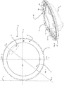
- a laundry treatment device realized according to the present invention are globally indicated with 1 and 100, respectively.
- the laundry treatment devices 1 and 100 are dryers, however the present teaching can be applied to washing machines and washer-dryers as well.
- Laundry treatment device 1; 100 comprises an outer box casing 7; 107 preferably but not necessarily parallelepiped-shaped, and a treatment chamber, such as a drum 3; 103 for example having the shape of a hollow cylinder, for housing the laundry and in general the clothes and garments to be washed and/or dried.
- the drum 3; 103 is preferably contained into the casing.
- drum 3; 103 can rotate around a preferably horizontal axis (in alternative embodiments, rotation axis may be vertical or tilted).
- Access to the drum 3; 103 is achieved for example via an opening 4; 104 formed on the casing 7; 107 itself. Opening 4; 104 preferably faces drum 3; 103 and it is apt to be closed - or even sealed - by a door assembly 10; 110.
- the door assembly 10; 110 is adapted to alternatively open and close the laundry loading opening 4; 104 of the laundry treatment device 1; 100 and is advantageously pivotally mounted, for example hinged, and thus supported at the casing 7; 107 of the device 1; 100.
- Door assembly 10; 110 can be operated, preferably, by a handle 31; 131 and better detailed below.
- casing 7; 107 generally includes a front wall 2; 102 to which the door assembly 10; 110 is pivotally mounted, a rear wall panel (not visible in the appended drawings) and two sidewall panels 71, 72; 171 a, 172 all mounted on a basement 74; 174.
- Casing 7; 107 is then topped by a top wall panel 73; 173.
- Front wall 2; 102, top wall 73; 173, sidewall panels 71, 72; 171 a, 172, rear wall panel and basement 74; 174 can be of any suitable material.
- the basement 74, 174 is made of plastic material.
- sidewall panels, front wall, rear wall, top wall and basement are separated pieces which are then assembled together via suitable fastening means.
- suitable fastening means for example lateral walls and rear wall can be a single U-shaped piece.
- Walls are preferably made of metal, however also plastic is possible. Also, in a non-depicted embodiment, some of the walls can be made of a material, and some other(s) can be made of a different material.
- a horizontal plane is defined (plane (XY) in Figure 1 and 9 ), which is generally the plane on which the bottom wall or basement 74; 174 lies and generally it is also parallel to the top wall 73; 173 of the casing 7; 107 in a mounted configuration.
- the device 1; 100 also extends along a vertical direction denoted with Z.
- the front wall 2; 102 includes an external continuous surface 2a; 102a having one or more openings, such as laundry opening 4; 104. Further openings, for example to house a control panel or a water or detergent drawer, etc. are also possible.
- the front external surface 2a; 102a of front wall 2; 102 is the external front surface of the device 1; 100.
- Front wall 2; 102 is preferably made of a metallic material, for example in stainless steel.
- the front surface 2a; 102a is preferably continuous and even more preferably seamless, at least in the visible portion(s) of the same.
- Continuous surface means that the surface is formed as a single member.
- Sealess means that, in addition to be continuous, there are no seams which indicate that for example welding has been used to join together different parts.
- portions of the front wall 2; 102 can be present. The absence of seams improves the overall appearance of the laundry treatment device 1; 100.
- the front wall 2; 102 preferably includes four rounded corners 4a, 4b, 4c, and 4d along its outer edge.
- "Rounded corner” means a corner which does not include sharp and abrupt changes in directions of the surfaces forming the same; on the contrary in a rounded corner the surfaces merges smoothly and with continuity. The round corners give a more aesthetically pleasant look to the device 1; 100.
- the front wall 2; 102 can be obtained by a single sheet of metal.
- it can be obtained by a sheet of stainless steel.
- the front wall can be coated by suitable coating to prevent corrosion.
- the front wall can be colored of any color and gloss.
- the front wall 2; 102 defines a top portion 4a', a middle portion 4a" and a bottom portion 4a"', the terms “top”, “middle” and “bottom” used with reference to the above defined standard standing configuration of the laundry treatment device 1, 100 when in use.
- only the top portion 4a' and the middle portion 4a" of the front wall 4 are a single (or one-piece) element, i.e., having a continuous and/or seamless front surface, while the bottom portion 4a"' is a separate piece and is to be assembled to the rest of the front wall.
- the opening 4; 104 and thus the door assembly 10; 110 are located in the middle portion 4a" of the front wall 2; 102.
- the front wall 2; 102 is not flat, i.e., it does not lie completely on a single plane. On the contrary, it includes a concavity pointing towards the inside of the casing 7; 107 being convex on the outside.
- the front wall 2; 102 - in a section along a plane parallel to the Z direction - has substantially a smoothed trapezoidal shape, the top 4a', the bottom 4a'" and the middle portion 4a" lying on three different planes which form an angle one with respect to the other(s) and also with the vertical direction Z defined by the casing 7; 107, forming in this way the inward concavity.
- the three planes are preferably connected smoothly and without sharp corners.
- the front wall 2; 102 are possible as well, for example the front wall can include a substantially constant curvature, the concavity still oriented towards the inside of the casing 7; 107.
- the front wall could be a portion of a cylindrical mantel.
- the middle portion 4a" including the opening 4; 104 defines a surface not parallel to the Z direction, but tilted with respect to the latter.
- the section of casing 7; 107 along a vertical plane parallel to side walls 71, 72; 171, 172 as in figs. 2 and 10 shows a slight inclination of portion 4a" with respect to the Z axis. Therefore it is preferred that the door assembly 10; 110 "matches" with this surface tilted with respect to the Z direction.
- Laundry treatment device 1; 100 also comprises an electrical motor (not shown) assembly for rotating, on command, revolving drum 3; 103 along its axis inside casing.
- Casing 7; 107 revolving drum 3; 103 and electrical motor are common parts in the technical field and are considered to be known; therefore they will not be described further in details.
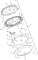
- door assembly 10; 110 includes a frame, which in turn includes two "half frames", a rear frame 5; 105 and a front frame 6; 106, one attached to the other.
- the door assembly 10; 110 can have two different operative positions or configurations: a closed position in which it is abutting against the front wall 2; 102, and an open position in which is separated from the front wall, with the exception of the connecting element (e.g., hinge) location.
- handle 31; 131 is used in order to move door assembly from the closed to the open configuration or vice-versa.
- rear frame 5; 105 is indicating in the following the portion of the frame of door assembly 10; 110 a surface of which, called rear surface 5b; 105b, is substantially in contact with casing 7; 107 when the door assembly 10; 110 is in the closed operative position (as shown in fig. 2 or fig. 10 ), while the front frame 6; 106 is defined as the portion of the frame of door assembly 10; 110 a surface of which, called front surface 6a; 106a, is mainly facing the exterior when the door assembly 10; 110 is closed onto casing 7; 107, i.e., it faces a direction opposite to the casing.
- front frame 6; 106 includes in addition to the front surface 6a; 106a also a rear surface 6b; 106b, the latter being apt to be in contact with or facing the rear frame 5; 105 when the door assembly 10; 110 is in an assembled configuration.
- rear frame 5; 105 includes a front surface 5a; 105a which is apt to be in contact with or facing rear surface 6b; 106b of front frame 6; 106 when the door assembly 10; 110 is in an assembled configuration, and it is also opposite to rear surface 5b; 105b in contact with the casing 7; 107 when door assembly 10;110 is mounted and in a closed operative position (as in figs. 2 and 10 ).
- rear and front frame 5, 6; 105, 106 are made of plastic, more preferably each of them is formed as an integral piece of plastic, for example by injection molding.
- front and rear frame 106, 105 of door assembly 110 are advantageously ring shaped, with respective central door apertures 109, 108 so as to form a substantially round-shaped door assembly 110, when connected one to the other.
- front frame 6 is also ring-shaped including an aperture 9, while rear frame is disc-shaped and does not include an aperture.
- shape of door assembly 10; 110 and thus of front and rear frame 6; 106, 5; 105 is arbitrary, for example the door assembly 10; 110 can be substantially polygonal, such as rectangular, quadratic, triangular, or elliptic when a front view of the same is considered.
- Door frame assembly 10; 110 when assembled, defines an outer perimeter edge 11;111, which is the outer contour of the frame.
- the outer perimeter edge 11; 111 describes a circumference, however any other shape is envisaged by the present invention depending on the door assembly final desired shape 10;110.
- an aperture 108, 109 in the frame of door assembly 110 is preferred when the laundry treatment device 100 is a washing machine so that an user can view the laundry from outside the casing 107 during the treatment cycles.
- the front and rear apertures 109, 108, of front and rear frame 106,105 of door assembly 110 as well as front aperture 9 of the front frame 6 of door assembly 10, have an arbitrary geometrical shape and they are advantageously closed or covered by an additional element.
- the aperture 9; 108, 109 is circular.
- the aperture 108 in rear frame 105 is closed by a door glass 180 having a bowl shape.
- door glass 180 is made of transparent glass capable of withstanding high temperatures and/or the chemicals which can be present in an embodiment in which the laundry treatment device 100 is a washing machine (embodiment not shown) during washing and/or drying cycles.
- the door glass 180 is assembled together with front and rear frame 106, 105 so as to close aperture 109, 108 preferably in an air-tight manner, so that no fluid can exits laundry treatment device 100 during operation.
- door glass 180 includes a flange 181 protruding in a radial direction around its periphery, and more preferably the flange 181 encircles the entire perimeter of the door glass 180.
- Flange 181 is preferably interposed between front and rear frame 106, 105 (see figure 14a and 14b ) when the door assembly 110 is in an assembled configuration.
- door glass 180 has a concave shape, and more specifically it is concaved toward drum 103, with the concave portion protruding inwards toward the drum 103 through opening 104 formed in front wall 102.
- a bowl-shaped element 80 is also present in embodiment of door assembly 10, however it is not a separate component, on the contrary it is an integral piece of rear frame 5, for example rear frame 5 including bowl-element 80 can be molded as a single block (see figs. 4 and 5 ).
- an inner edge or border 9a; 109a, 108a is consequently defined in the front 6; 106 and/or rear frame 105 itself as the edge of the door aperture 9; 109, 108.
- the rear surface 5a; 105a of rear door frame 5; 105 defines a closure plane PB.
- the closure plane is defined by the portion of rear surface that abuts on the casing 7; 107, when the door assembly 10; 110 is in a closed configuration on casing 7; 107.
- plane PB is parallel to an opening plane PC defined by the opening 4; 104 obtained in the front wall 2; 102.
- the opening plane PC is the plane on which the opening 4;104 lies.
- the opening plane PC and the closure plane PB may coincide or they can be one parallel to the other. Opening and closure plane PC, PB are better visible in figures 2 and 10 .
- closure plane PB and opening plane PC are substantially parallel to the Z axis.
- a closure plane and/or an opening plane tilted with respect to the Z axis are included as well.
- Front surface 6a; 106a of front frame 6; 106 also define a plane, called maximal area front plane PA.
- Front plane PA and closure plane PB form an angle ⁇ therebetween which is different from 0° and 180°, i.e., planes PA and PB are not parallel one to the other, but they are incident.
- the front frame plane PA is defined as follows.
- a "virtual" plane is considered and it is put into contact, again “virtually”, with the front surface 6a; 106a of the front frame 6; 106.
- the candidate front plane which defines the maximal virtual area on the front surface of front frame 6; 106 is the maximal area front plane.
- the area is calculated as follows, for each candidate front plane.
- all candidate front planes when put in contact to the front surface 6a; 106a of the front frame 6; 106, define, on the front surface, at least a closed curve or an area.
- the latter case takes place when the front surface 6a; 106a includes a planar (e.g., flat) portion.
- Each closed curve encircles an area.
- the candidate front plane is then the plane that forms the largest of these areas, the largest among all the areas encircled by the closed curves and the areas defined automatically by the direct contact between the candidate planes and the front surface 6a; 106a.
- candidate front plane(s) which, when in contact with the front surface 6a; 106a, do not form a closed curve.
- These candidate front planes might be the only defined candidate front planes in the door assembly of interest, or candidate front planes defining closed curves or areas can be present as well, e.g., a combination of candidate front planes forming closed curves or areas and candidate front planes not forming such closed curves can be defined.
- the locus of points of contact between the candidate front plane and the front surface includes at least a set of isolated points, or a set of isolated points and curves (not closed) or a set of curves separated one from the other.
- Connecting all elements of the set e.g., connecting all points and/or curves of the set via segments forms a closed curve.
- this closed curve defines an area, which is the area encircled by the closed curve.
- the largest area among all defined areas i.e., among the areas defined by candidate front planes which by themselves define closed curves or areas and the areas encircled by these closed curves initially formed by separated element, selects the front plane.
- the candidate front plane defining the largest area (regardless of how this area is formed, either directly, or as the internal area of the closed curve or as the internal area of the curve which is closed joining different points or curves) on the front surface is the maximal area front plane.
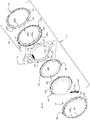
- the closure plane PB is depicted, as the vertical dashed line in figs. 21a, 22a, 23a , 24a and 25a : the closure plane is defined by the portion of rear frame that abuts against the front wall 2; 102 or casing 7; 107.
- Rear frame 5; 105 is not depicted for clarity.
- the door assembly 10; 110; 10PA is positioned parallel to the Z axis; however the closure plane PB could be tilted as well.
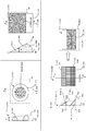
- Figs. 21b, 22b, 23b , 24b and 25b represent a front view of the five different embodiments of the door assembly 10; 110; 10PA, while figs. 21a, 22a, 23a , 24a, and 25a represent a section of the door assembly 10; 110; 10PA of figs. 21b, 22b, 23b , 24b, and 25b , respectively, along a vertical plane passing through the center axis of the respective front view (section along line A-A of the front views).
- Figures 21 a and 21 b, and 22a and 22b show two different embodiments of a door assembly 10; 110, in which a single location for a stable front plane is present.
- the front frame includes a prism "prism” having a triangular base and axis substantially perpendicular to the Z axis.
- a quarter of a cylinder “cylinder” is attached, the cylinder having an axis parallel to the axis of the triangular prism.
- the triangular prism has a right rectangle as a base, a side of which lies on the closure plane PB, the other side being in contact to the cylinder portion.
- the front surface 6a; 106a thus includes a rectangular flat portion, which is one side of the prism, and a curved portion being a portion of the outer surface of a cylindrical mantel of the cylinder.
- the outer edge 11; 111 of the frame is substantially rectangular.
- the section of the front frame along line A-A includes a triangle to the bottom base of which a quarter of circumference is connected.
- the front surface 6a; 106a includes as said a flat surface (a rectangle), therefore the area defined by "putting into contact a candidate front plane PA" onto the front surface of front frame corresponds to the area of the rectangular portion of the front surface itself.
- the plane PA defining an area equal to the area of the flat portion of front surface is the front plane itself.
- the gray area depicted in fig. 21b is therefore the area defined by the single candidate front plane which is also the front plane (or maximal area front plane).
- planes PA and PB define an angle ⁇ therebetween different from 0° and 180°.
- the front frame is torus-shaped, defining aperture 9; 109, where the torus has a generating circumference having variable diameter, in particular it has its minimal diameter at its top-most edge and its maximal diameter at the lower-most edge.
- the outer edge 11; 111 of the frame is thus a circumference, as visible in fig. 22b .
- the front surface 6a; 106a includes a portion of a torus outer surface.
- a closed curve in this particular case an ellipse, i.e., the locus of points of the contact between the front surface 6a; 106a and the candidate plane PA is an ellipse, which is a closed curve.
- This closed curve of contact is represented in fig. 22b as a dashed line.
- the area internal to this curve (which, as said, is an ellipse) is the area defined by the candidate front plane. It is clear that this area includes portions of the front surface 6a; 106a, as well as additional portions, such as portions of aperture 9; 109 (in this case the whole area of the aperture). In this case, there is no comparison to be made among different areas because a single candidate front plane PA is present which is the front plane. No other plane can be stably positioned on the front surface.
- FIGS 23a-23c an embodiment of a door assembly 10;110, in which five different candidate front planes PA1, PA2, PA3, PA4, PA5 are defined is depicted.
- Figures 23a and 23b corresponds to the same view of figures 21 a,22a and 21 b,22b above described.
- the front frame of this embodiment has a substantially rectangular outer edge 11;111 and includes an aperture 9; 109 substantially centrally located.
- the rectangle defined by edge 11,111 has two opposite sides, in particular the top most and lower most side with respect to the Z axis, substantially parallel to the (X,Y) plane.
- the front frame 6; 106 of this embodiment includes, in a position corresponding to the top most and lower most sides, two prisms "prism 1 and "prism 2" having a triangular base.
- the two triangular prisms have an axis perpendicular to the Z axis and are positioned one on top of the other.
- the base triangle of each prism is a right triangle, which one side lying on the closure plane PB. Therefore, the section of the front frame 6; 106 along the vertical plane defines two triangles, one for each prism, as visible in fig. 23a ; thus a top-most and lower-most triangle are formed.
- the two triangles have different dimensions.
- Five candidate front planes are defined by the present front frame of this embodiment:
- FIG 23b the virtual surface areas defined by the candidate front planes P1-P5 in a front view of the door assembly 10; 110 are shown.
- Surface areas defined by PA4 and PA5 are perpendicular to the drawing and thus are not visible.
- the area defined by P5 is less extended than the area defined by PA3 and the area defined by PA4 is smaller than the area defined by PA1, so they cannot define the maximal area and thus none of them can be the front plane of this door assembly 10; 110.
- the first virtual area defined by PA1 is represented as a rectangle filled with diagonal lines.
- the second virtual area defined by PA2 is represented as a rectangle filled with horizontal lines.
- the third virtual area defined by PA3 is also a rectangle that overlaps completely with the second virtual area and is filled with vertical lines. It is clear from the drawing that the maximal area, i.e., the most extended area, is the one defined by PA3 which is then the front plane.
- Figs. 24a and 24b shows an embodiment of a door assembly 10; 110 where the front frame has the same layout as in the embodiment of figs. 23a-23c and in addition, in the location of front frame where in figs. 23a-23c the aperture 9; 109 is present, a half cylindroid "cylindroid" is realized covering the aperture completely.
- the half cylinder has an axis which is positioned parallel to the axis of the two triangular prisms.
- the section of this door assembly defines two triangles and a semi-ellipsoid in between the two triangles, without any overlap between the various geometrical figures.
- the candidate front planes which are definable in this embodiment are:
- the third plane PA3 sections a portion of the front frame, e.g., it sections the central half-cylindroid.
- the curve defined by the sectioned portion is not part of the closed curve which encircles the area defined by the third plane and thus it is acceptable according to the set rules.
- the closure plane PB and the front plane PA form an angle therebetween, i.e., they are not parallel.
- This angle ⁇ can vary in values, as long as it is different from 0° and 180°. Preferably it is smaller than 10 °.
- the front frame includes a parallelepiped portion in the center of which a half-cylinder is positioned.
- the front frame defines a rectangle on which - in the central portion - a half-circumference is located protruding outwardly from the rectangle.
- the parallelepiped portion is positioned with two opposite faces substantially parallel to the closure plane PB.
- the front surface 6a; 106a of this embodiment includes two opposite faces, flat surfaces, of the parallelepiped and one portion, substantially perpendicular to the two faces, which is partly flat and partly a portion of a cylinder mantel. Five candidate front planes are thus defined:
- the front 6; 106 and rear frame 5; 105 define two different planes, PB and PA, which are not parallel one to the other. Due to the fact that the front and the closure plane PA, PB form an angle ⁇ therebetween different from 0° and 180°, the frame including front frame 6; 106 and rear frame 5; 105 does not have a uniform thickness in proximity of its perimeter edge 11; 111. Preferably, the thickness of the frame changes gradually and continuously along its edge 11; 111, from a minimum to a maximum thickness.
- the thinnest portion of door frame in proximity of its edge and the thickest portion of door frame in proximity of its edge 11; 111 are located in such a way that one is the reflection of the other across an axis of the door assembly 10; 110.
- this axis is perpendicular to a hinge axis H of rotation of the door assembly 10; 110 when the latter is assembled on the casing 7; 107 and more preferably this axis passes through a geometrical center of the door assembly.
- the top-most portion of the frame which includes a first portion of the edge 11; 111, and the lower-most portion of the frame, including a second portion of the edge 11; 111, are respectively the thinner and thickest portion of the frame which contains the edge of the same.
- the shown door assembly 10 has a thickness T1, which is the thinnest thickness of the frame along its edge, in a portion of front frame 6 which is top-most located when the door assembly 10 is attached to the casing 7, while it has a thickness T2, which is the thickest thickness of the door frame along its edge 11, in a portion of door frame which is lower-most located when the door assembly 10 is attached to casing 7.
- Planes PA and PB are depicted as well.
- the frame may include thicker or thinner portions than the portions having thickness T1 and/or T2 in its geometrical layout, however these additional portions do not include the edge 11; 111 of the frame.
- An example is the embodiment depicted in fig. 24a , where the central cylinder can be thicker, in its central portion, than the prism, so defining a thicker thickness of the frame in that position than in the lower-most edge portion of the frame..
- Front frame 6; 106 and rear frame 5; 105 can be realized as a single piece or as an assembly of different pieces.
- the front frame 6 includes a single piece
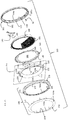
- the front frame 106 includes a first element 170 and a cover ring 150.
- Cover ring 150 includes the front surface 106a of front frame 106 and it represents the "most external" element of the door assembly 110, when the latter is coupled to casing 107.
- the cover ring 150 gives a better aesthetic appearance to the door assembly 110, covering all possible holes and elements present in the front frame to couple the same to the rest of the door assembly.
- the front frame aperture 109 is thus formed by two overlapping apertures realized in the first element 170 and in the cover ring 150 which, when the front frame 106 is assembled, define a single inner edge 109a of the aperture 109.
- the shapes of the first element 170 and of the cover ring 150 are similar.
- the front frame 6; 106 and the rear frame 5; 105 are coupled one to the other, preferably in a removable manner.
- the coupling is obtained by means of coupling elements 21; 121 and corresponding coupling counter elements 22; 122 formed in the front and rear frame, respectively.
- said coupling elements 21; 121 extend from the rear surface 6b; 106b of the front frame 6; 106 while said coupling counter elements 22; 122 extend from the front surface 5a; 105a of said rear frame 5; 105.
- coupling elements 21; 121 extend substantially perpendicularly to the rear surface 6b; 106b of front frame 6; 106, at least locally, e.g. they are substantially perpendicular to the portion of the rear surface from which they depart.
- counter elements 122 extend perpendicularly, at least locally, to the front surface 105a of rear frame 105, while counter elements 22 have substantially a negligible height or extension.
- each coupling element 21; 121 includes an appendix 90, 190.
- the appendix 90; 190 includes a tubular sleeve 91; 191, having an open end.
- the element 21; 121 may include a cylindrical rod. It is desired that the dimensions of the sleeves and/or cylindrical rods, e.g., the diameters of elements and counter-elements, are such that the elements can be inserted within the counter elements or vice-versa.
- the insertion of the elements into the counter-elements or vice-versa is obtained with interference so that, when a coupling element is inserted in a coupling counter element (or vice-versa) the removal requires the application of a non-negligible force, so that the possibility of accidental removals is minimized.
- each coupling element 21 departing from the rear surface 6b of front frame 6 includes a tubular sleeve 91 departing from a pedestal 92.
- the tubular sleeve is not directly connected to the rear surface 6b of front frame 6, but it is positioned on the pedestal 92.
- Coupling counter-elements 22 are realized as through holes on rear frame 5, in which the tubular sleeve 91 of coupling elements 21 can be inserted. Instead of through-holes, coupling counter-elements 22 could include appendices 90 as well.
- coupling elements 21 includes tubular sleeves 91 and not cylindrical rod, so that fastening screws 25 can be inserted from rear surface 5b of rear frame 5 into the through-holes defined by coupling counter-elements 22 and then into the tubular sleeves 91 of coupling elements 21, so as to better fasten front and rear frame 6, 5 together.
- the cover ring 150 in the embodiment of door assembly 110, as better visible in figs. 14a and 14b , which are enlarged views of two portions of fig. 12 which is in turn a section of fig. 11 along line B-B, the cover ring 150, part of the front frame, includes a rear surface 151, facing the first element 170, from which the elements 121 depart.
- the first element 170 includes a plurality of through holes 171 through which the coupling elements 121 are inserted.
- the coupling elements 121 are thus also protruding from the rear surface 106b of the first element 170.
- the coupling elements 121 are substantially perpendicular to both rear surface 151 and rear surface 106b.
- Coupling element 121 includes a tubular sleeve 191 departing from a pedestal 192.
- the tubular sleeve is not directly connected to the rear surface 151 of cover ring 150, but it is positioned on the pedestal 192.
- Coupling counter-element 122 departing from the front surface 105a of rear frame 105 includes a tubular sleeve 191 directly departing from the front surface 105a.
- Each appendix 190a which is pierced, also includes a pedestal 192a on which a tubular sleeve 191 a is mounted.
- the shape and dimensions of pedestal 192a and tubular sleeve 191 a are such that each appendix 190 can enter completely in a respective appendix 191 a, with pedestal 192 abutting to an inner top surface of pedestal 192a and sleeve 191 protruding outside sleeve 191 a.
- rear surface 151 of cover ring 150 is in contact to front surface 177 of first element 170, so that the two surfaces are substantially parallel.
- the coupling elements 21; 121 and the coupling counter-elements 22; 122 are located in the front 6; 106 and rear frame 5; 105, respectively, in proximity of the outer edge 11; 111 of the door frame. More preferably, the coupling elements 21; 121 and counter elements 22; 122 are angularly spaced one from the other, even more preferably with a substantially constant spacing one from the other so that the whole extension of the edge 11; 111 contour of the door frame is substantially followed by the elements and counter elements.
- a counter element 22; 122 is present in the rear frame 5; 105 in a bijection correspondence.
- coupling elements 21; 121 and/or coupling counter elements 22; 122 are integrally formed with the front 6; 106 and/or rear frame 5; 105.
- elements and/or counter elements are made of plastic material, so that elements and counter elements are realized with the respective front and rear frame in a single molding process.
- either the coupling elements 21; 121, or the coupling counter-elements 22, 122, or both have different heights among themselves.
- either the plurality of elements 21; 121 includes at least a first element having a first height D1 different from a height D2 of a second element of the plurality, or the plurality of counter elements 22; 122 includes at least a first counter element having a first height D1 different from a height D2 of a second counter element of the plurality.
- both plurality of elements 21; 121 and counter elements 22; 122 include, within the same plurality, two elements/counter elements having different heights.
- the plurality of coupling elements 21; 121 and/or the plurality of coupling counter elements 22; 122 include a plurality of different heights so that the thickness of the frame of the door assembly 10; 110 can vary continuously and smoothly. Being the elements and counter-elements located in correspondence of the edge of the frame 11; 111, having a plurality of different heights allow to give to the frame a continuous variation in thickness at its edge 11; 111.
- coupling counter-elements 22 are through-holes and thus have a substantially negligible height which is thus equal among all coupling counter-elements.
- the front frame 6, as better visible in fig. 6 includes a plurality of coupling elements 21 having different heights extending from the rear surface 6b of front frame 6. These elements 21 include sleeves 91, all having the same height, positioned on respective pedestals 92 which have different heights; thus also coupling elements 21 have different heights among themselves. Preferably, a plurality of different heights is defined in the pedestals. Even more preferably, a number of different heights equal to the number of coupling elements 21 is present.
- the plurality of counter-elements 22 have different heights from a minimum height D1 in the top-most portion of the front frame 6 to a maximum height D2 in the lower-most portion of the front frame 6.
- rear frame 5 further includes a plurality of centering-elements 23 protruding from front surface 5a, substantially perpendicularly to the latter.
- Centering elements 23 are located in proximity of the edge of rear frame 5, in a radially inward position with respect to the position of coupling counter-elements 22 and they are angularly spaced one from the others.
- These centering-elements 23 also, among themselves, have different heights, from a maximum height L2 at the lower-most portion of rear frame 5 and a minimum height L1 at the top-most portion of rear frame 5.
- the function of these centering elements 23 is three-folds: to support of additional elements positioned on top of the rear frame, to improve the centering of such additional elements and to avoid rotations of the same, as better detailed below.
- Figs. 17 and 18 show in an enlarged view the cover ring 150 of door assembly 110 from which the plurality of elements 121 departs.
- Each element 121 includes a tubular sleeve 191 surmounting a pedestal 192.
- Tubular sleeves 191 have all the same height, while pedestals 192 have a height which changes from a minimum to a maximum, so that the elements 121 include the tallest element with height D2 and the shortest element with height D1, and preferably also a plurality of coupling elements having intermediate height between D1 and D2.
- Coupling counter-elements 122 of door assembly 110 protrude from the front surface 105a of rear frame 105 and include tubular elements 191 departing directly from the front surface 105a. No pedestal is present.
- the counter-elements 122 have all the same height.
- the coupling between the front frame 6; 106 and the rear frame 5; 105 is realized by inserting the coupling elements 21; 121 into the coupling counter-elements 22; 122. At the same time, due to the different heights of the coupling elements 21; 121 and/or coupling counter elements 22; 122, the resulting thickness of the frame at its edge 11; 111 varies depending on the position along the edge itself.
- coupling elements 122 are inserted in holes 171 and appendices 190a.
- Appendices 190a are located around first element 170 in correspondence of appendices 190 of cover ring 150.
- Pedestals 192a have also different heights, matching the height difference of the pedestals 192, so that each pedestal 192 is in abutment against the inner top surface of pedestal 192a and surfaces 151 and 177 are parallel one to the other.
- tubular sleeves 191 a The height of tubular sleeves 191 a is constant and so dimensioned that, when front frame and rear frame are assembled together, tubular sleeves 191 of coupling elements 121 protrude from tubular sleeves 191 a and the free end of tubular sleeve 191 a is in abutment against the free end of tubular sleeves 191 of coupling counter elements 122, where the tubular sleeves 191 of coupling elements 121 are inserted.
- This abutment takes place for all appendices 190a and coupling counter elements 122.
- the free ends on coupling counter elements 122 and the free ends of appendices 190a define two planes, which are parallel and more preferably coincident.
- This matching of planes or in other words this abutment of sleeves, improves the solidity of the frame and avoids any translational movements of the components of the same.
- the coupling elements 21; 121 and counter-elements 22; 122 can be used not only to couple front 6; 106 and rear frame 5; 105 together, but also to determine the angle ⁇ different from 0° and 180° between the front plane PA and the closure plane PB due to their different heights.
- the "tilt" present between the front PA and closure plane PB can be created in other ways and it is not necessary that the front 6; 106 and rear frame 5; 105 are coupled using coupling elements 21; 121 and coupling counter-elements 22; 122 having different heights.
- coupling elements 21; 121 and coupling counter-elements 22; 122 may have many different other shapes and configurations than the tubular one above described.
- cap element 140 In the embodiment of door assembly 110, with particular reference to figs. 13 , 15 , 16 as well as 14a and 14b, a different element, called cap element 140, than the coupling elements and counter-elements creates the "tilt" between the front plane PA and the closure plane PB, so that they are not parallel.
- Cap element 140 defines an outer edge 145 which is sandwiched between front and rear frame 106, 105.
- Cap element includes a plate-like member 146 which covers completely the apertures 108,109 formed in the frame.
- the shape of the cap element, and in particular of the plate-like member 146 corresponds substantially to the shape of the front and rear frame 106, 105 so that a good aesthetic match can be provided.
- the function of the cap-element 140 is two-folds.
- a protective element is interposed between the user and the glass door.
- This protective element is the cap element 140 which is mounted between the front frame and the glass door so as to cover completely the glass door itself.
- the plate-like member 146 thus defines the most external surface of the door assembly which is located in the aperture 109 of front frame 106 and which is accessible to the user for contact.
- plate-like member 146 is made of plastic and even more preferably it is made of a transparent, or at least semi-transparent, plastic material.
- the cap element 140 has two opposite first and second sides, one facing the glass door 180 and the other facing the front frame 106, when the door assembly 110 is in an assembled configuration.
- the first side facing the glass door 180 defines a first surface 141 which defines a first plane.
- the second side facing the front frame 106 defines a second surface 142 which in turn also defines a second plane. These two first and second planes are not parallel to each other; on the contrary they form an angle therebetween.
- the first surface 141 defining the first plane is the surface which is in abutment to the neighbouring element to cap element 140 located behind the cap element 140 when the door assembly 110 is in an assembled configuration.
- surface 141 is the surface which is in abutment against glass door 180 and/or rear frame 105.
- the second surface 142 defining the second plane is the surface which is in abutment to the neighbouring element of the door assembly located directly in front of the cap element 140 when the door assembly 110 is in an assembled configuration on casing 107.
- any element abutting on one side of the cap element 140 is automatically tilted with respect to another element abutting on the opposite side of the cap element.
- any further component mounted on them remains substantially parallel to the closure plane PB.
- Cap element 140 abuts with its first surface 141 against the glass door 180: the first plane defined by the first surface 141 is therefore parallel to the closure plane PB.
- second surface 142 of the cap element 140 angled with respect to the first surface 141, it means that second plane defined by the second surface 142 is also angled with respect to the closure plane PB.
- Any component mounted, e.g. in abutment against, the second surface 142 of the cap element 140 results thus tilted with respect to the closure plane of the angle present between the first and second plane defined by the first and second surface 141, 142 of cap element 140.
- the tilt can be realized as follows: in the second side of the cap element 140 facing the front frame 106, a ridge 143 can be formed.
- the ridge 143 can be for example be formed in an edge surface 145a of cap element 140.
- Edge surface 145a is an annular surface containing the outer edge 145 of cap element 140 and extending in a radially inward direction towards the center of the cap element 140.
- the ridge 143 may have different heights along its extension depending on its position.
- the ridge 143 has the shortest height at a location which is the top-most one when door assembly 110 is mounted on casing 107, and the highest height at a location which is the lower-most one when door assembly is mounted on casing 7.
- the ridge 143 having different thicknesses can be seen clearly in fig. 13 where a section along the vertical center-plane of door assembly 110 is depicted (line B-B of figure 11 ).
- Figs. 14a and 14b although not depicting the top-most and lower-most portion of door assembly 110, show also a difference in the height of the ridge 143 in two different portions of the frame.
- the second surface 142 is thus formed by the top of ridge 143 which have a variable height and thus the second plane lying on such a second surface results tilted.
- the first surface 141 is, in this embodiment, the surface of the plate-like member 146 facing casing 107.
- ridge 143 could be formed in the first surface as well.
- the first plane defined by the first surface 141 results substantially parallel to the closure plane PB and the second plane defined by the second surface 142 results substantially parallel to the front plane PA.
- the angle formed between the first and second plane defined by cap element 140 is equal to ⁇ .
- the coupling elements and/or counter-elements 121,122 could have also all the same height, because they are not necessary to form the "tilt", however coupling elements 121 and/or coupling counter-elements 122 with different heights allow a better coupling of components lying on different planes.
- the door assembly 10; 110 further includes the handle 31; 131 so that it can be moved from an open to a closed position and vice-versa.
- the handle 31; 131 is coupled to a handle-carrying element 30; 130 which carries the handle 31; 131.
- the handle-carrying element 30; 130 is positioned, e.g., partially sandwiched, between the front 6; 106 and rear frame 5; 105 of door assembly 10; 110.
- the handle-carrying element defines an outer edge 32; 132 which is sandwiched between the front 6; 106 and the rear frame 5; 105.
- the handle-carrying element 30; 130 is so construed that relative movements between the handle 31; 131 and the element 30; 130 are not possible, i.e., handle 31; 131 is firmly fixed on handle-carrying element 30; 130.
- handle 31; 131 has an elongated shape defining a first and a second distal ends 31a, 31b; 131a, 131b.
- Handle 31; 131 preferably belongs to a system which may be named "pull-to-open" door opening system: the door assembly 10; 110 is provided with a latch, and the casing 7; 107, preferably front wall 2; 102, is provided with a latch retaining mechanism that includes a mobile part which is configured to be movable between a retaining position, in which it engages the latch so as to retain the door assembly in the closed condition, and an opening position in which it releases the latch so as to allow the opening of the door assembly.
- the mobile part of the latch allows the releasing of the latch when a releasing force is applied which is greater than a threshold force, as better described below.
- the door assembly is therefore opened by pulling it outwards with enough force, and can also be opened by pushing it from the inside of the treatment chamber 3; 103.
- the handle 31; 131 of the door assembly 10; 110 has only the function of providing a grip to the user, and it is fixed to the frame of door assembly via the handle-carrying element 30; 130.
- the handle-carrying element 30; 130 does not change the angle between the front frame PA and the closure frame PB; in other words it is not responsible for tilting any part of the front frame with respect to the rear frame or vice-versa. Therefore, the insertion of the handle-carrying element 30; 130 between the front 6; 106 and rear frame 5; 105 does not modify the angle formed between the above defined closure and front frame.
- the outer edge 32; 132 of handle-carrying element 30; 130 has thus preferably substantially an uniform thickness.
- both door assembly 10 and 110 includes a front frame 6; 106 defining an internal opening 9; 109.
- handle 31; 131 is located at the aperture 9; 109, and it extends in a radially inward direction from the inner edge 9a; 109a of the aperture 9; 109.
- the door assembly of the invention is reversible, i.e., door assembly 10; 110 can be mounted in a right-hand configuration or in a left-hand configuration.
- the handle-carrying element 31 of door assembly 10 includes a plate-like member 33, substantially disc-shaped, the outer edge 32 of which is sandwiched between the front 6 and rear frame 5.
- the plate-like member 33 is substantially a single element realized integral to the handle 31.
- the handle is realized at the outer edge 32 of the plate-like member 33, protruding in a radially outward direction from the outer edge 32 and defining a radial protuberance of plate-like member 33.
- the plate-like member when the door assembly is in an assembled configuration as depicted in fig. 3 , covers completely aperture 9.
- the diameter of plate-like member 33 is substantially identical to the diameter of aperture 9.
- Plate like member 33 includes a surface 33a which results visible from the exterior of casing 7, when door assembly 10 is in an assembled configuration and closed on casing 7, and which is adjacent to the front surface 6a of door assembly 10.
- surface 33a is substantially flush with front surface 6a of front frame 6.
- Handle 31 results visible from the outside of casing 7 and it includes a recess 34, which is best visible in fig. 5 where the door is sectioned along a plane sectioning also the handle 31 ( figure 5 is the section along line B-B of fig. 3 ).
- the recess 34 is a recess in the surface 33a at the edge 32 and it extends underneath the front frame, so that the front frame itself forms a gripping element for the user's fingers when he/she introduces the hand in the recess 34 in order to open the door assembly 10.
- the handle 31 is partly formed by the plate-like member 33 and partly by the front frame 6, that is to say, by a cooperation of the two.
- Handle-carrying element 30 is preferably realized in plastic material.
- Handle-carrying element 30 is preferably coupled directly to front frame 6.
- the plate like member 33 thus further includes, extending from its edge 32, an annular flange 36, substantially perpendicular to the plate-like member 33.
- a terminal end of annular flange 36, or at least of portions of the terminal end of annular flange 36, is folded in itself, defining a seat 37 formed by parallel walls defined by the annular flange's fold.
- the front frame 6, in its rear surface 6b, includes also a protruding flange 39 which is insertable or inserted in seat 37, preferably with interference.
- the coupling between the flange 39 and seat 37 is clearly visible in fig. 5 .
- Protruding flange 39 preferably extends from the rear surface 6b of front frame 6 substantially perpendicularly to the rear surface itself.
- Protruding flange 39 which is to be inserted in seat 37, is interrupted in at least four locations, by four different C-shaped wall members 38 mating the boundary external contour of the handle 31. Thus flange 39 is separated in at least four different portions.
- handle-carrying element 30 is inserted in the aperture 9, the annular flange 36 being in contact to the edge 9a of the aperture 9 and to the flange 39.
- the insertion terminates when flange 39 reaches the bottom of seat 37.
- Seat 37 and flange 39 are so dimensioned that the outer surface 33a results flush with the front surface 6a of front frame 6.
- handle 31 is inserted within one of the C-shaped wall members 38, as better described below.
- two coupling elements 21 are positioned, one coupling element at each end.
- each of the two distal ends 31 a, 31 b of the handle 31 is located substantially adjacent to a coupling element 21 (see fig. 6 ).
- the handle-carrying element 130 of door assembly 110 includes a ring-like member 133, the outer edge 132 of which is sandwiched between the front 106 and rear frame 105.
- the handle-carrying element 130 has a central aperture 134, preferably having the same shape as the apertures 108 and 109, so that a good aesthetic appearance is obtained.
- the ring-like member 133 is substantially a single element realized integral to the handle 131.
- the handle is realized at an inner edge 134a of the aperture 134 of ring-like member 133, in other words, handle 131 includes a portion of aperture's edge 134a and it protrudes in a radially inward direction from the latter.
- Ring- like member 133 when the door assembly 110 is in an assembled configuration as depicted in fig. 19a , overlaps apertures 109, 108.
- Ring- like member 133 includes a portion, preferably a ring portion 138 (see figures 19a and 20a ) around the inner edge 134a of aperture 134, which results visible from the exterior of casing 107 and which form a portion of the outer surface of door assembly 110.
- the visible ring portion 138 is substantially flush with front surface 106a of front frame 106.
- Handle 131 results visible from the outside of casing 107 and it includes a flap element 135 connected to the visible ring portion 138 and extending toward the center of aperture 134.
- Ring-like member 133 further includes flat appendices, for example in the number of four, all indicated with 139, which protrudes in a radially outward direction from the outer edge 132 of ring-like member 133.
- the appendices 139 are angularly spaced one from the others with a fixed spacing.
- Each flat appendix 139 includes a notch 137, having a shape and dimensions suitable to house a coupling element 121 and/or a coupling counter element 122. Referring back to figures 15 and16, flat appendices 139 are sandwiched between front 106 and rear frame 105.
- Door assembly 10, 110 further comprises a hinge 60; 160, which is provided to pivot the door assembly 10; 110 to the casing 7; 107 so that it can be opened by rotating it about a hinge axis H, as shown in figs. 3 , 5c , and 19a, 20a .
- hinge 60; 160 is arranged across, and more preferably centered across, a horizontal median plane of the door assembly 10; 110 substantially perpendicular to hinge axis H.
- the horizontal median plane defines center line C, which is an axis passing through the center of the front section of the door assembly.
- a vertical median plane V is also defined, as the plane parallel to the hinge or rotational axis H and passing through the geometrical center of the door assembly.
- hinge axis is parallel to the Z axis and centerline C is parallel to the (X,Y) plane, i.e. it is an horizontal axis.
- Hinge 60; 160 may be any conventional hinge, preferably of the type that is not visible when the door assembly 10; 110 is closed.
- hinge 60; 160 comprises a portion (not visible in the figures) fixed to the front wall 2; 102, a seat 62; 162 for housing it provided in the door assembly 10; 110, and a hinge pin 63; 163 extending in holes of the portion fixed to front wall and of the seat 62: 162.
- an electromechanical lock (not all components of which are visible) is provided between the door assembly 10; 110 and the front wall 2; 102.
- the lock comprises a portion or first member fixed to the front wall 2; 102 and a portion or second, matching member fixed to the door assembly 10; 110 that cooperate with each other.
- the lock is configured to avoid opening of the door assembly during operation of the laundry treatment device 1; 100; and to possibly to avoid operation of the device with the door assembly open, for example by issuing a consent signal to an electronic control unit of the device only when the door assembly is closed and/or delay opening of the door assembly after the end of an operation cycle.
- the electromechanical lock is therefore also an interlock.
- the second member comprises a hook or latch 61; 161 protruding from the door assembly 10; 110 towards the casing 7; 107 and the first member comprises a latch retaining mechanism for receiving the hook or latch 61; 161, positioned at the casing 7; 107.
- the latch retaining mechanism preferably includes, in a manner known per se, a mobile part which is configured to be movable between a retaining position, in which it engages the hook or latch 61; 161 so as to retain the door assembly 10; 110 in a closed condition, and an opening position it which it releases the hook or latch 61; 161 so as to allow the opening of the door assembly 10; 110.
- the mobile part of the latch retaining mechanism at the front wall 2; 102 preferably interacts with an elastic element, for example a spring, which allows the releasing of the hook or latch 61; 161 when a releasing force is applied which is greater than a threshold force.
- the door assembly is therefore, as already mentioned, of the "pull-to-open type", opened by applying a force beyond a threshold onto the door assembly 10; 110 away from the casing 7; 107.
- the lock is preferably arranged across, and more preferably centered across, the horizontal centerline C of the door assembly 10; 110. Therefore, hinge 60; 161 and lock lie substantially on the same axis C.
- cap member 40 includes seat 62 for the housing of the hinge 60 and an additional seat (not visible in the drawings) for the housing of the hook or latch 61 (see figs. 6 and 7 ).
- Cap element 40 visible in an enlarged view in fig. 8 , is sandwiched between rear frame 5 and front frame 6 in correspondence of its edge 47 and it covers at least in part the aperture 9 realized in the front frame.
- Cap element 40 is covered by handle-carrying element 30, which covers aperture 9 completely, when the door assembly 10 is in an assembled configuration, therefore it is not visible from the outside, with the exception of part of hinge 60 and latch 61 which have to be mounted on or cooperate with casing 7.
- cap element 40 in proximity of its edge 47, includes a first and a second plurality of through holes 44 and 48 through which coupling elements 21 and centering- elements 23 can pass. Coupling elements 21 and centering elements 23, when inserted in holes 44 and 48, respectively, avoids any rotation of cap element 40.
- Cap element 40 does not change the inclination present between the front plane PA and the closure plane PB, in other words the angle between these two planes is unchanged with or without the presence of cap element 40.
- cap element 40 includes a strengthening member 46, substantially centrally located, which reinforces front frame 6 and in particular handle-carrying element 30.
- a strengthening member 46 substantially centrally located, which reinforces front frame 6 and in particular handle-carrying element 30.
- a large gap is present within door assembly 10 in an assembled configuration between bowl-shaped element 80 and the plate-like member 33 of handle-carrying element 30.
- the presence of a central strengthening member 46 of cap element 40 avoids that pressure applied on plate-like member 33 could break the latter.
- cap element 40 is shown mounted on rear frame 5.
- the centering-elements 23 protruding from rear surface 5b of rear frame 5 are inserted into through holes 48 and protrude from the latter.
- the different heights of centering-elements 23 are visible, being the thickness of cap element 40 substantially constant.
- hinge 160 and hook or latch 161 are mounted, in a reversible manner, on rear frame 105, at the edge of the same, where the seat 162 is formed.
- the handle 31; 131 when door assembly 10; 110 is in an assembled configuration, is provided at a location which is not aligned or not corresponding with the position of the lock, e.g., hook or latch 61; 161 and of handle 60; 160.
- the handle 31; 131 is arranged outside the horizontal median plane C of the door assembly 10; 110.
- the handle 31; 131 is thus offset with respect to hinge 60; 160 and the lock. In case of a large extent of the handle 31; 131 and/or of the lock and/or of the hinge, hinge and handle and/or hinge and lock might however overlap in part.
- the handle-carrying element 30; 130 can be positioned between the front 6; 106 and rear frame 5; 105 at least in two different positions and more preferably in at least four different positions. The difference between one position and the other lies in the handle location: for each position of the handle-carrying element 30; 130 a different location L1, L2, L3, L4 of the handle 31; 131 within the frame is achieved.
- door assembly 110 depicted in figures 19a-19c and 20a-20c , the same description - unless otherwise specified - is applicable also to door assembly 10.
- the door assembly 110 is in a left-hand configuration being hinged at its left (as viewed from the front of the laundry treatment device 100 when the door assembly 110 is closed), i.e., the rotation axis, or hinge axis, H is on the left side of the door assembly.
- the hinge 160 is advantageously centered across a position at 9 o'clock or 180° in a conventional angular reference system (see figure 19a ), and the latch 161 is across a position at 3 o'clock or 0° in the same reference system (see figure 19c which is the rear view of the door assembly 110 of fig. 19a ).
- the reference system is defined by centerline C and vertical centerline V, parallel to hinge axis H.
- the axes C and V of door assembly 110 are also indicated in figs. 19a and 20a to easily identify four quadrants.
- handle 131 is shown arranged in the first quadrant, i.e., between 0° and 90°.
- the handle 131 extends for an arc or circumference lying in the generally central portion of the first quadrant. This position is indicated with "L1".
- the handle 131 may be arranged in the fourth quadrant, i.e. between 270° and 360°, as shown in fig. 19a with a dotted line. This position is called "L2".
- position L2 corresponds to the reflection of the position L1 of handle 131 across the centerline C.
- the handle 131 may be arranged in the third quadrant, i.e. between 180°and 270°as shown in fig. 20a . This is position "L3".
- the handle 131 may be arranged in the second quadrant, i.e. between 90°and 180°. This is the position "L4".
- position L4 corresponds to the reflection of the position L3 of handle 131 across the centerline C.
- position L4 corresponds to the reflection of the position L1 of handle 131 across the vertical centerline V.
- position L3 corresponds to the reflection of the position L2 of handle 131 across the vertical centerline V.
- handle 131 and hook or latch 161 are arranged such that, when the door assembly is closed, they are located at angular positions that are reciprocally spaced by less than 90°.
- hinge 160 and handle 131 are arranged such that, when the door assembly is closed, they are located at angular positions that are reciprocally spaced by more than 90°.
- the assembly of the door assembly 10 takes place as follows.
- cap element 40 On cap element 40, hinge 60 and latch or hook 61 are attached.
- the cap element 40 is positioned on door frame 5 in such a way that the centering elements 23 are inserted into through-holes 48 of the cap element 40 and the through-holes 44 are aligned with the through-holes defined by the coupling counter-elements 22. Suitable recesses or openings are realized in the edge of rear door frame 5 so that the hinge 60 and the latch or hook 61 can protrude rearward outside the door assembly 10.
- Handle-carrying element 30 is inserted into opening 9 of front door frame 6, till the flange 39 abuts onto the bottom of seat 37.
- the handle 31 is positioned within one of the C-shaped wall members 38 which substantially defines a seat for the handle 31 itself.
- C-shaped wall members 38 are formed at locations L1, L2, L3, and L4 for handle 31.
- the C-shaped wall member 38 is chosen among the four available ones according to the desired location of handle 31 to be achieved in the assembled door assembly 10.
- Front frame 6 including handle-carrying element 30 is then mounted on rear frame 5 including cap element 40 and fastened inserting the coupling elements 21 first into the through holes 44 in cap element 40 and then into the coupling counter elements 22 in rear frame 5, by the application of pressure.
- the centering-elements 23 are so located to substantially abut against the terminal end of flange 36, in other words against seat 37, so as to keep the seat 37 pressed against flange 39 of the front frame 5 and avoid possible expulsion of the latter.
- the centering elements 23 define, by means of their free ends, a plane which is tilted with respect to the closure plane, due to their different heights. More preferably this plane is parallel, even more preferably is coinciding to the handle plane. Therefore, when the door assembly is in an assembled configuration, the free ends of centering elements 23 define the plane on which the handle-carrying element 30 should lay. In this way, movements of the handle-carrying element 30 towards or away the front frame 6, thus movements of the handle plane, are avoided, because an abutment is present of the centering elements 23 against flange 36 for all the angular extension of the latter.
- Additional fastening elements might be present to fix the front 6 and rear door frame 5 together, such as screws and bolts or snap-fit elements.
- screws 25 are inserted into through holes defined by the coupling counter-elements 22 from the rear surface 5b of rear frame 5 and screwed into the tubular elements 91 of coupling elements 21.
- rear door frame 5 and cap element 40 lie on planes substantially parallel to closure plane PB, while front door frame and handle-carrying element 30 are substantially lying, at least on one side, on the front plane PA.
- Rear door frame 5 has two opposite surfaces 5a and 5b.
- Surface 5b defines closure plane PB.
- Surface 5a also defines a plane; the portion of surface 5a to be considered for the definition of the plane is the one which is in abutment against the "neighbouring" component of the door assembly 10, in this case cap element 40.
- This portion of surface 5a is planar and defines a plane which is parallel to the closure plane, due to the front frame layout.
- a component lying on such a plane defined by surface 5a is also, as far as the surface of the component lying on such a plane is concerned, parallel to the closure plane.
- Cap element 40 in the same way, defines two opposite surfaces forming two opposite planes.
- Cap element 40 is so construed that these two opposite surfaces and planes are parallel to each other and thus result parallel to closure plane PB, due to the fact that cap element 40 is in abutment against front surface 5a of rear frame 5 which defines a plane parallel to PB.
- the handle-carrying element 30 mounted directly onto the front door frame 6 which defines a front plane which is "tilted" with respect to the closure plane PB due to the different heights of coupling elements 21, it lies on a tilted plane with respect to the closure plane as well.
- the front door frame 6 Being the top-most element(s) 21 the shortest, the front door frame 6 is in the top-most position closer to the closure plane PB than in the lower-most position, where the element(s) 21 is the longest, so the front door frame in this position is the farthest from the closure plane PB.
- the front frame 6 defines the front plane PA by means of front surface 6a.
- Rear surface 6b defines a plane as well, for example parallel to PA. Therefore any component abutting on such a plane remains, at least for the surface in abutment, parallel to PA.
- the handle-carrying element 30 can define, by means of one of its opposite surfaces, a plane, called handle plane PH, which can be tilted with respect to the closure plane of a different angle than the angle ⁇ present between the front plane PA and the closure plane PB.
- a further angle or tilt has to be realized between the front frame 6 and the handle-carrying element 30, i.e. between the front plane PA and handle plane PH.
- the location of the handle 31 has to move from the location indicated with L1 in figure 19a (although these figures refers to door assembly 110, the possible locations of the handle are applicable to door assembly 10 as well) to the location indicated with L4 in figure 20a .
- the front 6 and rear frame 5 have to be released one from the other.
- the front and rear frame 6,5 can be completely detached or simply a gap can be formed therebetween, without a complete separation of the two elements.
- the cap element 40 which is carrying the hinge 60 and latch or hook 61, is rotated by 180° so that the position of the hinge and latch or hook are exchanged.
- the rotation of the cap element 40 takes place on a plane parallel to the closure plane PB.
- Cap element 40 is then inserted again into centering-elements 23.
- the handle-carrying element 30 is then also rotated, but of an angle smaller than 180°: it has to be rotated of the angle present between location L1 and L4. This rotation takes place on a plane which is the handle plane PH, tilted with respect to the closure plane and preferably parallel to the front plane PA.
- Front and rear frame 6, 5 are then fastened again one on the other, inserting the coupling elements into the holes 44 and coupling counter-elements 22, and finally screws 25 are inserted in the holes defined by coupling counter-elements 22 and screwed in tubular elements 91
- handle 31 has to be moved, in the same manner above described, from location L3 to location L2.
- the laundry treatment device 1 changes position from a floor-positioned device with handle 31 in position L1 to an "elevated" position
- the handle 31 from location L1 preferably is to be moved to location L2 in order to be more easily accessible to the user.
- the front 6 and rear frame 5 have to be released one from the other.
- the front and rear frame 6, 5 can be completely detached or simply a gap can be formed therebetween.
- the handle-carrying element 30 is rotated, again of an angle smaller than 180°: it has to be rotated of the angle present between location L1 and L2.
- This rotation takes place on a plane which is the handle plane PH, tilted with respect to the closure plane and preferably parallel to the front plane PA.
- the meaning of a rotation on plane PH is the same as above.
- Front and rear frame 6, 5 are then fastened again one on the other.
- handle 31 has to be moved from location L3 to location L4.
- Door assembly 10 is then hinged on front wall 2. Due to the tilt present between the front plane PA and the closure plane PB, the front surface 6a defining the front plane matches with the portion of front surface 2a of front wall 2 in which opening 4 is formed. Indeed, preferably such front surface 2a, around opening 4, is tilted as well.
- the assembly of the door assembly 110 is performed in the following way.
- hinge 160 and latch or hook 161 are attached.
- both glass door 180 and cap element 140 include an outer edge the dimensions of which are such that it is insertable within the contour defined by the coupling counter-elements 122 protruding from front surface 105a of rear frame 105.
- both glass door 180 and cap element 140 includes anti-rotational means, for example protrusions extending radially from their respective outer edges, to avoid rotations of the glass door and/or cap element.
- Handle-carrying element 130 is put into abutment against the second surface 142 of cap element with the handle 31 in the desired angular location among the available possibilities, such as L1, L2, L3 and L4. Notches 137 prevent further rotations of the handle-carrying element 130 after assembly due to the presence within each notch 137 of a coupling element 121 or counter-element 122.
- the first element 170 of front frame 106 is then mounted on rear frame 105, on top of handle-carrying element 130.
- Cover ring 150 is then positioned on top of the first member 170 so that the coupling elements 121 are inserted into through holes 171, in appendices 190a of the first element 170 and then into coupling counter-elements 122, fastening the front and rear frame together.
- Additional fastening elements might be present to fix the front 106 and rear door frame 105 together, such as screws and bolts or snap-fit elements.
- screws 125 are inserted into through holes defined by the coupling counter-elements 122 from the rear surface 105b of rear frame 105 and screwed into the tubular elements 191 of coupling elements 121 and coupling counter elements 122.
- the tilt is determined by the difference in the heights of ridge 143.
- the handle-carrying element 130 can define, by means of one of its opposite surfaces, a plane, called handle plane PH, which can be tilted with respect to the closure plane of a different angle than the angle ⁇ present between the front plane PA and the closure plane PB.
- a further angle or tilt has to be realized between the front frame 6 and the handle-carrying element 130, i.e. between the front plane PA and handle plane PH.
- the location of the handle 131 has to move from the location indicated with L1 in figure 19a to the location indicated with L4 in figure 20a .
- the front and rear frame have to be released one from the other.
- the front and rear frame 106,105 can be completely detached or simply a gap can be formed therebetween.
- the rear frame 105 which is carrying the hinge 160 and latch or hook 161 is rotated by 180° so that the position of the hinge and latch or hook are exchanged.
- the rotation of the rear frame 105 takes place on a plane parallel to the closure plane PB.
- the handle-carrying element 130 is then also rotated, but of an angle smaller than 180°: it has to be rotated of the angle present between location L1 and L4. This rotation takes place on a plane which is the handle plane PH, tilted with respect to the closure plane and preferably parallel to the front plane PA.
- Front and rear frame 106,105 are then fastened again one on the other as already described.
- handle 131 has to be moved, in the same manner above described, from location L3 to location L2.
- the laundry treatment device 100 changes position from a floor-positioned device with handle in position L1 to an "elevated" position
- the handle from location L1 preferably moves to location L2 in order to be more easily accessible to the user.
- front and rear frame have to be released one from the other.
- the front and rear frame 106,105 can be completely detached or simply a gap can be formed therebetween,
- the handle-carrying element 130 is rotated, again of an angle smaller than 180°: it has to be rotated of the angle present between location L1 and L2. This rotation takes place on a plane which is the handle plane PH, tilted with respect to the closure plane and preferably parallel to the front plane PA.
- Front and rear frame 106, 105 are then fastened again one on the other.
- handle 131 has to be moved from location L3 to location L4.
- Door assembly 110 is then hinged on front wall 102. Due to the tilt present between the front plane PA and the closure plane PB, the front surface 106a defining the front plane matches with the portion of front surface 102a of front wall 102 in which opening 104 is formed. Indeed, preferably such front surface 102a, around opening 104, is tilted as well.
- locating elements can be provided, to avoid that in a left-hand door configuration locations L3 or L4 are selected, and similarly, in a right-hand configuration, to avoid that locations L1 or L2 are selected by the user.
Claims (18)
- Ensemble de porte (10 ; 110) pour un dispositif de traitement de linge (1 ; 100) apte à ouvrir et/ou fermer une ouverture (4 ; 104) définie dans ledit dispositif de traitement de linge, ledit ensemble de porte comprenant un cadre (5, 6 ; 105, 106), ledit cadre comprenant :- un cadre de porte avant (6 ; 106) formant une surface avant (6a ; 106a) de l'ensemble de porte, ladite surface avant définissant un plan avant (PA) ;- un cadre de porte arrière (5 ; 105) formant une surface arrière (5b ; 105b) dudit ensemble de porte, ladite surface arrière définissant un plan de fermeture (PB),caractérisé en ce que ledit plan avant (PA) et ledit plan de fermeture (PB) se coupent l'un l'autre de manière à former un angle (α) différent de 0° et de 180°; et en ce que ledit cadre comporte en outre- un élément de support de poignée (30 ; 130) interposé entre ledit cadre de porte arrière (5 ; 105) et ledit cadre de porte avant (6 ; 106), et une poignée (31 ; 131) portée par ledit élément de support de poignée, ledit élément de support de poignée étant apte à être monté dans au moins une première et une deuxième positions alternatives, de telle sorte que ladite poignée (31 ; 131) puisse être positionnée sur ledit cadre au moins dans un premier et un deuxième endroits différents (L1 ; L2 ; L3 ; L4).
- Ensemble de porte (10 ; 110) selon la revendication 1, dans lequel :- ledit élément de support de poignée (30 ; 130) est conçu de telle sorte que lesdites première et deuxième positions alternatives soient séparées par une rotation dudit élément de support de poignée (30 ; 130) sur un plan de poignée (PH); et- ledit plan de poignée (PH) et ledit plan de fermeture (PB) se coupent l'un l'autre manière à former un angle (α) différent de 0° et de 180°.
- Ensemble de porte (10 ; 110) selon la revendication 2, dans lequel ledit plan de poignée (PH) et ledit plan avant (PA) sont substantiellement parallèles.
- Ensemble de porte (10 ; 110) selon l'une quelconque des revendications précédentes, dans lequel ledit élément de support de poignée (30 ; 130) est construit de telle sorte que lesdites première et deuxième positions alternatives soient séparées par une rotation dudit élément de support de poignée (30 ; 130) d'un angle compris entre 0° et 180°.
- Ensemble de porte (10 ; 110) selon l'une quelconque des revendications précédentes dans lequel ledit élément de support de poignée (30 ; 130) est apte à être monté dans au moins ladite première, ladite deuxième et une troisième et une quatrième positions alternatives, de telle sorte que ladite poignée (31 ; 131) puisse être positionnée sur ledit cadre dans au moins quatre endroits différents (L1 ; L2 ; L3 ; L4), au moins deux (L1, L3 ; L2, L4) desdites première, deuxième, troisième et quatrième positions étant le reflet l'une de l'autre à travers un axe, lesdites au moins deux positions coïncidant avec une position pour un ensemble de porte pour droitier par rapport à un axe (H) de l'ouverture de l'ensemble de porte et avec une position pour un ensemble de porte pour gaucher par rapport à l'axe (H) de l'ouverture de l'ensemble de porte.
- Ensemble de porte (10 ; 110) selon l'une quelconque des revendications précédentes, dans lequel lesdites première et/ou deuxième positions différentes (L1 ; L2 ; L3 ; L4) de ladite poignée (31) est/sont située (s) à un angle donné entre 0° et 90° à partir d'un axe médian (C) dudit ensemble de porte sensiblement perpendiculaire à un axe (H) d'ouverture dudit ensemble de porte.
- Ensemble de porte (10 ; 110) selon l'une quelconque des revendications précédentes, comportant un élément de capuchon (40 ; 140) interposé entre ledit cadre de porte avant (6 ; 106) et ledit cadre de porte arrière (5 ; 105) et ledit cadre de porte avant et/ou ledit cadre de porte arrière comportant en outre une ouverture avant et/ou arrière (9 ; 108, 109), respectivement, et ledit élément de capuchon (40 ; 140) couvrant au moins en partie ladite ouverture avant et/ou arrière.
- Ensemble de porte (110) selon la revendication 7, dans lequel ledit élément de capuchon (140) définit une première surface (141) en regard dudit cadre de porte arrière (105) ou dudit cadre de porte avant (106) et étant substantiellement parallèle audit plan de fermeture (PB), et une deuxième surface (142), opposée à la première surface (141) et faisant face à l'autre dudit cadre de porte avant (106) ou dudit cadre de porte arrière (105), ladite deuxième surface (142) définissant un plan qui coupe ledit plan de fermeture (PB) de manière à former un angle différent de 0° et de 180°.
- Ensemble de porte (110) selon la revendication 8, dans lequel ledit élément de capuchon (140) présente une surface de bord extérieur (145a) interposée entre ledit cadre de porte arrière et ledit cadre de porte avant, et ladite deuxième surface (142) comporte une arête (143) faisant saillie vers l'extérieur depuis ladite deuxième surface (142) et située à proximité de ladite surface de bord extérieur (145a) ou au niveau de celle-ci, ladite arête (143) ayant une première hauteur au niveau d'une première partie de ladite surface de bord extérieur et une deuxième hauteur au niveau d'une deuxième partie de ladite surface de bord extérieur, la première hauteur étant différente de la deuxième hauteur.
- Ensemble de porte (110) selon l'une quelconque des revendications 7 à 9, dans lequel ledit élément de support de poignée (130) bute contre ladite deuxième surface (142), et ledit plan de poignée (PH) est substantiellement parallèle audit plan défini par ladite deuxième surface (142).
- Ensemble de porte (10 ; 110) selon l'une quelconque des revendications précédentes, dans lequel ledit cadre de porte avant (6 ; 106) et/ou ledit cadre de porte arrière (5 ; 105) comportent en outre une ouverture avant et/ou arrière (9 ; 108, 109), respectivement, définissant un bord intérieur respectif (9a ; 108a ; 109a), ladite poignée (31 ; 131) étant située au niveau dudit bord intérieur.
- Ensemble de porte (10 ; 110) selon l'une quelconque des revendications précédentes, dans lequel ladite poignée (31 ; 131) est formée intégralement avec ledit élément de support de poignée (30 ; 130).
- Ensemble de porte (10 ; 110) selon l'une quelconque des revendications précédentes, comprenant un ou plusieurs élément(s) de positionnement, configuré(s) de telle sorte que ledit élément de support de poignée (30 ; 131) puisse présenter seulement deux positions (L1, L2) pour un ensemble de porte pour gaucher, et seulement deux positions (L3, L4) pour un ensemble de porte pour droitier.
- Ensemble de porte (110) selon l'une quelconque des revendications précédentes, dans lequel ledit cadre de porte avant (106) comporte une ouverture de porte avant (109) et un anneau de recouvrement (150) ayant une ouverture d'anneau de recouvrement (109), ledit anneau de recouvrement étant attaché audit cadre de porte avant (106) de telle sorte que ladite ouverture d'anneau de recouvrement (109) corresponde substantiellement à ladite ouverture de porte avant (109).
- Dispositif de traitement de linge (1 ; 100), comprenant :- une enceinte (7, 107) contenant une chambre de traitement (3 ; 103) destinée à recevoir une charge à traiter,- une paroi avant (2 ; 102) couvrant un côté de ladite enceinte (7 ; 107), ladite paroi avant comportant une ouverture (4 ; 104) permettant accéder à ladite chambre de traitement;- un ensemble de porte (10 ; 110) associé à ladite enceinte pour ouvrir et/ou fermer ladite ouverture, caractérisé en ce que ledit ensemble de porte est formé selon une ou plusieurs des revendications 1 à 14.
- Procédé pour modifier la position d'une poignée (31 ; 131) dans un ensemble de porte (10 ; 110) associé à un dispositif de traitement de linge (1 ; 100), ledit ensemble de porte comprenant :- un cadre de porte avant (6 ; 106) formant une surface avant (6a ; 106a) de l'ensemble de porte, ladite surface avant définissant un plan avant (PA) ;- un cadre de porte arrière (5 ; 105) formant une surface arrière (5b ; 105b) dudit ensemble de porte, ladite surface arrière définissant un plan de fermeture (PB) ;- un élément de support de poignée (30 ; 130) interposé entre ledit cadre de porte arrière (5 ; 105) et ledit cadre de porte avant (6 ; 106), et une poignée (31 ; 131) couplée audit élément de support de poignée;- dans lequel ledit plan avant (PA) et ledit plan de fermeture (PB) se coupent l'un l'autre de manière à former un angle différent de 0° et de 180°,le procédé étant caractérisé en ce qu'il comprend les étapes suivantes :- détacher ledit cadre de porte avant (6 ; 106) dudit cadre de porte arrière (5 ; 105) ;- tourner ledit élément de support de poignée (30 ; 130) sur un plan de poignée (PH) incliné par rapport audit plan de fermeture (PB) d'un angle différent de 0° et 180°; et- attacher ledit cadre de porte avant (6 ; 106) audit cadre de porte arrière (5 ; 105).
- Procédé selon la revendication 16, dans lequel ledit ensemble de porte (10 ; 110) comporte une charnière (60 ; 160) et une partie d'un mécanisme de verrouillage de porte (61 ; 161), ledit procédé comprenant en outre l'étape consistant à :- échanger la position de la charnière (60 ; 160) et de la partie du mécanisme de verrouillage de porte (61 ; 161).
- Procédé selon la revendication 17, dans lequel ladite charnière (60 ; 160) et ladite partie du mécanisme de verrouillage de porte (61 ; 161) sont connectées audit cadre de porte arrière (105) ou audit élément de capuchon (40), le procédé comportant en outre l'étape consistant à :- tourner ledit cadre de porte arrière (105) ou ledit élément de capuchon (40) de substantiellement 180°.
Priority Applications (5)
| Application Number | Priority Date | Filing Date | Title |
|---|---|---|---|
| PL13182520T PL2843105T3 (pl) | 2013-08-30 | 2013-08-30 | Zespół drzwiowy dla urządzenia do obróbki prania i sposób jego eksploatacji |
| EP13182520.0A EP2843105B1 (fr) | 2013-08-30 | 2013-08-30 | Ensemble de porte pour dispositif de traitement du linge et procédé de fonctionnement |
| AU2014314518A AU2014314518B2 (en) | 2013-08-30 | 2014-07-31 | A door assembly for a laundry treatment device and method of operation |
| CN201480048092.9A CN105492680A (zh) | 2013-08-30 | 2014-07-31 | 用于衣物处理装置的门组件和操作方法 |
| PCT/EP2014/066484 WO2015028246A1 (fr) | 2013-08-30 | 2014-07-31 | Ensemble porte pour un dispositif de traitement de linge, et procédé de fonctionnement |
Applications Claiming Priority (1)
| Application Number | Priority Date | Filing Date | Title |
|---|---|---|---|
| EP13182520.0A EP2843105B1 (fr) | 2013-08-30 | 2013-08-30 | Ensemble de porte pour dispositif de traitement du linge et procédé de fonctionnement |
Publications (2)
| Publication Number | Publication Date |
|---|---|
| EP2843105A1 EP2843105A1 (fr) | 2015-03-04 |
| EP2843105B1 true EP2843105B1 (fr) | 2017-01-18 |
Family
ID=49083568
Family Applications (1)
| Application Number | Title | Priority Date | Filing Date |
|---|---|---|---|
| EP13182520.0A Active EP2843105B1 (fr) | 2013-08-30 | 2013-08-30 | Ensemble de porte pour dispositif de traitement du linge et procédé de fonctionnement |
Country Status (5)
| Country | Link |
|---|---|
| EP (1) | EP2843105B1 (fr) |
| CN (1) | CN105492680A (fr) |
| AU (1) | AU2014314518B2 (fr) |
| PL (1) | PL2843105T3 (fr) |
| WO (1) | WO2015028246A1 (fr) |
Families Citing this family (16)
| Publication number | Priority date | Publication date | Assignee | Title |
|---|---|---|---|---|
| EP3061863B1 (fr) * | 2015-02-27 | 2020-01-22 | Electrolux Appliances Aktiebolag | Sèche-linge |
| EP3061862B1 (fr) * | 2015-02-27 | 2019-07-31 | Electrolux Appliances Aktiebolag | Sèche-linge |
| AU2016223373B2 (en) * | 2015-02-27 | 2020-08-20 | Electrolux Appliances Aktiebolag | Laundry drying machine |
| KR101708351B1 (ko) | 2015-11-02 | 2017-02-20 | 엘지전자 주식회사 | 의류처리장치 |
| KR101708355B1 (ko) | 2015-11-02 | 2017-02-20 | 엘지전자 주식회사 | 의류처리장치 |
| CN105908453B (zh) | 2015-11-02 | 2018-07-24 | Lg电子株式会社 | 衣物处理装置 |
| CN206070193U (zh) | 2015-11-02 | 2017-04-05 | Lg电子株式会社 | 衣物处理装置 |
| KR101708354B1 (ko) | 2015-11-02 | 2017-02-20 | 엘지전자 주식회사 | 의류처리장치 |
| CN106012440B (zh) | 2015-11-02 | 2018-09-14 | Lg电子株式会社 | 衣物处理装置 |
| CN105937150B (zh) * | 2016-06-30 | 2018-04-24 | 无锡小天鹅股份有限公司 | 用于衣物处理机的门体组件和具有其的衣物处理机 |
| CN206127678U (zh) * | 2016-07-04 | 2017-04-26 | 青岛海尔洗涤电器有限公司 | 非对称玻璃窗的洗衣机门体及洗衣机 |
| JP2018075144A (ja) * | 2016-11-08 | 2018-05-17 | リンナイ株式会社 | 衣類処理機 |
| CN109385851A (zh) * | 2017-08-10 | 2019-02-26 | 青岛海尔滚筒洗衣机有限公司 | 一种滚筒洗衣机及控制方法 |
| CN109554902A (zh) * | 2017-09-27 | 2019-04-02 | 青岛海尔洗衣机有限公司 | 一种观察窗及干衣机 |
| CN110042624B (zh) * | 2018-01-15 | 2021-12-03 | 佛山海尔滚筒洗衣机有限公司 | 衣物处理设备的门组件和衣物处理设备 |
| DE102022205165A1 (de) * | 2022-05-24 | 2023-11-30 | BSH Hausgeräte GmbH | Wäschepflegegerät zum Pflegen von Gegenständen |
Family Cites Families (9)
| Publication number | Priority date | Publication date | Assignee | Title |
|---|---|---|---|---|
| KR100465691B1 (ko) * | 2002-01-17 | 2005-01-13 | 엘지전자 주식회사 | 드럼 세탁기의 도어 장착구조 |
| KR100595180B1 (ko) * | 2002-07-31 | 2006-07-03 | 엘지전자 주식회사 | 빨래건조기/드럼세탁기의 도어 |
| CN1683695A (zh) * | 2004-04-12 | 2005-10-19 | 乐金电子(天津)电器有限公司 | 滚筒洗衣机的倾斜型门的铰链系统 |
| EP2147996B1 (fr) * | 2008-07-23 | 2014-04-16 | Electrolux Home Products Corporation N.V. | Ensemble de porte réversible pour machine de traitement du linge à chargement frontal |
| US8127464B2 (en) | 2009-07-31 | 2012-03-06 | Bsh Home Appliances Corporation | Front ring for a household appliance door |
| US8661860B2 (en) * | 2009-07-31 | 2014-03-04 | Bsh Home Appliances Corporation | Door bowl for a household appliance door |
| DE102011078920A1 (de) * | 2011-07-11 | 2013-01-17 | Bosch-Siemens Hausgeräte Gmbh | Beschickungstür für eine Wäschebehandlungsmaschine |
| JP5383878B2 (ja) * | 2011-12-12 | 2014-01-08 | シャープ株式会社 | 洗濯機 |
| DE102012202745B4 (de) * | 2012-02-22 | 2021-06-10 | BSH Hausgeräte GmbH | Tür für ein Haushaltsgerät und Verfahren zum Wechsel eines Türanschlags |
-
2013
- 2013-08-30 EP EP13182520.0A patent/EP2843105B1/fr active Active
- 2013-08-30 PL PL13182520T patent/PL2843105T3/pl unknown
-
2014
- 2014-07-31 WO PCT/EP2014/066484 patent/WO2015028246A1/fr active Application Filing
- 2014-07-31 AU AU2014314518A patent/AU2014314518B2/en active Active
- 2014-07-31 CN CN201480048092.9A patent/CN105492680A/zh active Pending
Non-Patent Citations (1)
| Title |
|---|
| None * |
Also Published As
| Publication number | Publication date |
|---|---|
| AU2014314518A1 (en) | 2016-03-10 |
| CN105492680A (zh) | 2016-04-13 |
| WO2015028246A1 (fr) | 2015-03-05 |
| AU2014314518B2 (en) | 2019-01-17 |
| EP2843105A1 (fr) | 2015-03-04 |
| PL2843105T3 (pl) | 2017-07-31 |
Similar Documents
| Publication | Publication Date | Title |
|---|---|---|
| EP2843105B1 (fr) | Ensemble de porte pour dispositif de traitement du linge et procédé de fonctionnement | |
| AU2014314517B2 (en) | Door assembly for a laundry treatment device | |
| JP4636148B2 (ja) | ドラム式洗濯機 | |
| JP5618517B2 (ja) | 電気洗濯機 | |
| US8127464B2 (en) | Front ring for a household appliance door | |
| AU2014314511B2 (en) | Door assembly for a laundry treatment device | |
| KR20030060557A (ko) | 드럼세탁기의 도어 | |
| AU2014314512B2 (en) | A door assembly for a laundry treatment device and method of operation | |
| CN105937137A (zh) | 衣物处理装置 | |
| EP2871279B1 (fr) | Machine à laver et procédé de fabrication de sa porte | |
| AU2017362549B2 (en) | A door assembly for a laundry treatment machine | |
| JP2009213804A (ja) | ドラム式洗濯機 | |
| EP3323928B1 (fr) | Ensemble porte pour machine de traitement de linge et procédé pour modifier la position d'une poignée dans ledit ensemble porte | |
| KR200395273Y1 (ko) | 세탁기의 전면부 구조 | |
| JP5707523B2 (ja) | 電気洗濯機 | |
| EP3323927B1 (fr) | Ensemble porte pour machine de traitement de linge | |
| JP6177822B2 (ja) | 電気洗濯機 | |
| JP6295356B2 (ja) | 電気洗濯機 | |
| JP2018117889A (ja) | 衣類処理装置 |
Legal Events
| Date | Code | Title | Description |
|---|---|---|---|
| 17P | Request for examination filed |
Effective date: 20130830 |
|
| AK | Designated contracting states |
Kind code of ref document: A1 Designated state(s): AL AT BE BG CH CY CZ DE DK EE ES FI FR GB GR HR HU IE IS IT LI LT LU LV MC MK MT NL NO PL PT RO RS SE SI SK SM TR |
|
| AX | Request for extension of the european patent |
Extension state: BA ME |
|
| PUAI | Public reference made under article 153(3) epc to a published international application that has entered the european phase |
Free format text: ORIGINAL CODE: 0009012 |
|
| R17P | Request for examination filed (corrected) |
Effective date: 20150904 |
|
| RBV | Designated contracting states (corrected) |
Designated state(s): AL AT BE BG CH CY CZ DE DK EE ES FI FR GB GR HR HU IE IS IT LI LT LU LV MC MK MT NL NO PL PT RO RS SE SI SK SM TR |
|
| GRAP | Despatch of communication of intention to grant a patent |
Free format text: ORIGINAL CODE: EPIDOSNIGR1 |
|
| INTG | Intention to grant announced |
Effective date: 20160928 |
|
| GRAS | Grant fee paid |
Free format text: ORIGINAL CODE: EPIDOSNIGR3 |
|
| GRAA | (expected) grant |
Free format text: ORIGINAL CODE: 0009210 |
|
| AK | Designated contracting states |
Kind code of ref document: B1 Designated state(s): AL AT BE BG CH CY CZ DE DK EE ES FI FR GB GR HR HU IE IS IT LI LT LU LV MC MK MT NL NO PL PT RO RS SE SI SK SM TR |
|
| REG | Reference to a national code |
Ref country code: GB Ref legal event code: FG4D |
|
| REG | Reference to a national code |
Ref country code: CH Ref legal event code: EP |
|
| REG | Reference to a national code |
Ref country code: AT Ref legal event code: REF Ref document number: 862989 Country of ref document: AT Kind code of ref document: T Effective date: 20170215 |
|
| REG | Reference to a national code |
Ref country code: IE Ref legal event code: FG4D |
|
| REG | Reference to a national code |
Ref country code: DE Ref legal event code: R096 Ref document number: 602013016657 Country of ref document: DE |
|
| REG | Reference to a national code |
Ref country code: NL Ref legal event code: MP Effective date: 20170118 |
|
| REG | Reference to a national code |
Ref country code: LT Ref legal event code: MG4D |
|
| REG | Reference to a national code |
Ref country code: AT Ref legal event code: MK05 Ref document number: 862989 Country of ref document: AT Kind code of ref document: T Effective date: 20170118 |
|
| PG25 | Lapsed in a contracting state [announced via postgrant information from national office to epo] |
Ref country code: NL Free format text: LAPSE BECAUSE OF FAILURE TO SUBMIT A TRANSLATION OF THE DESCRIPTION OR TO PAY THE FEE WITHIN THE PRESCRIBED TIME-LIMIT Effective date: 20170118 |
|
| PG25 | Lapsed in a contracting state [announced via postgrant information from national office to epo] |
Ref country code: HR Free format text: LAPSE BECAUSE OF FAILURE TO SUBMIT A TRANSLATION OF THE DESCRIPTION OR TO PAY THE FEE WITHIN THE PRESCRIBED TIME-LIMIT Effective date: 20170118 Ref country code: FI Free format text: LAPSE BECAUSE OF FAILURE TO SUBMIT A TRANSLATION OF THE DESCRIPTION OR TO PAY THE FEE WITHIN THE PRESCRIBED TIME-LIMIT Effective date: 20170118 Ref country code: NO Free format text: LAPSE BECAUSE OF FAILURE TO SUBMIT A TRANSLATION OF THE DESCRIPTION OR TO PAY THE FEE WITHIN THE PRESCRIBED TIME-LIMIT Effective date: 20170418 Ref country code: LT Free format text: LAPSE BECAUSE OF FAILURE TO SUBMIT A TRANSLATION OF THE DESCRIPTION OR TO PAY THE FEE WITHIN THE PRESCRIBED TIME-LIMIT Effective date: 20170118 Ref country code: IS Free format text: LAPSE BECAUSE OF FAILURE TO SUBMIT A TRANSLATION OF THE DESCRIPTION OR TO PAY THE FEE WITHIN THE PRESCRIBED TIME-LIMIT Effective date: 20170518 Ref country code: GR Free format text: LAPSE BECAUSE OF FAILURE TO SUBMIT A TRANSLATION OF THE DESCRIPTION OR TO PAY THE FEE WITHIN THE PRESCRIBED TIME-LIMIT Effective date: 20170419 |
|
| PG25 | Lapsed in a contracting state [announced via postgrant information from national office to epo] |
Ref country code: RS Free format text: LAPSE BECAUSE OF FAILURE TO SUBMIT A TRANSLATION OF THE DESCRIPTION OR TO PAY THE FEE WITHIN THE PRESCRIBED TIME-LIMIT Effective date: 20170118 Ref country code: AT Free format text: LAPSE BECAUSE OF FAILURE TO SUBMIT A TRANSLATION OF THE DESCRIPTION OR TO PAY THE FEE WITHIN THE PRESCRIBED TIME-LIMIT Effective date: 20170118 Ref country code: PT Free format text: LAPSE BECAUSE OF FAILURE TO SUBMIT A TRANSLATION OF THE DESCRIPTION OR TO PAY THE FEE WITHIN THE PRESCRIBED TIME-LIMIT Effective date: 20170518 Ref country code: ES Free format text: LAPSE BECAUSE OF FAILURE TO SUBMIT A TRANSLATION OF THE DESCRIPTION OR TO PAY THE FEE WITHIN THE PRESCRIBED TIME-LIMIT Effective date: 20170118 Ref country code: SE Free format text: LAPSE BECAUSE OF FAILURE TO SUBMIT A TRANSLATION OF THE DESCRIPTION OR TO PAY THE FEE WITHIN THE PRESCRIBED TIME-LIMIT Effective date: 20170118 Ref country code: BG Free format text: LAPSE BECAUSE OF FAILURE TO SUBMIT A TRANSLATION OF THE DESCRIPTION OR TO PAY THE FEE WITHIN THE PRESCRIBED TIME-LIMIT Effective date: 20170418 Ref country code: LV Free format text: LAPSE BECAUSE OF FAILURE TO SUBMIT A TRANSLATION OF THE DESCRIPTION OR TO PAY THE FEE WITHIN THE PRESCRIBED TIME-LIMIT Effective date: 20170118 |
|
| REG | Reference to a national code |
Ref country code: DE Ref legal event code: R097 Ref document number: 602013016657 Country of ref document: DE |
|
| PG25 | Lapsed in a contracting state [announced via postgrant information from national office to epo] |
Ref country code: CZ Free format text: LAPSE BECAUSE OF FAILURE TO SUBMIT A TRANSLATION OF THE DESCRIPTION OR TO PAY THE FEE WITHIN THE PRESCRIBED TIME-LIMIT Effective date: 20170118 Ref country code: RO Free format text: LAPSE BECAUSE OF FAILURE TO SUBMIT A TRANSLATION OF THE DESCRIPTION OR TO PAY THE FEE WITHIN THE PRESCRIBED TIME-LIMIT Effective date: 20170118 Ref country code: EE Free format text: LAPSE BECAUSE OF FAILURE TO SUBMIT A TRANSLATION OF THE DESCRIPTION OR TO PAY THE FEE WITHIN THE PRESCRIBED TIME-LIMIT Effective date: 20170118 Ref country code: SK Free format text: LAPSE BECAUSE OF FAILURE TO SUBMIT A TRANSLATION OF THE DESCRIPTION OR TO PAY THE FEE WITHIN THE PRESCRIBED TIME-LIMIT Effective date: 20170118 |
|
| PLBE | No opposition filed within time limit |
Free format text: ORIGINAL CODE: 0009261 |
|
| STAA | Information on the status of an ep patent application or granted ep patent |
Free format text: STATUS: NO OPPOSITION FILED WITHIN TIME LIMIT |
|
| PG25 | Lapsed in a contracting state [announced via postgrant information from national office to epo] |
Ref country code: SM Free format text: LAPSE BECAUSE OF FAILURE TO SUBMIT A TRANSLATION OF THE DESCRIPTION OR TO PAY THE FEE WITHIN THE PRESCRIBED TIME-LIMIT Effective date: 20170118 Ref country code: DK Free format text: LAPSE BECAUSE OF FAILURE TO SUBMIT A TRANSLATION OF THE DESCRIPTION OR TO PAY THE FEE WITHIN THE PRESCRIBED TIME-LIMIT Effective date: 20170118 |
|
| 26N | No opposition filed |
Effective date: 20171019 |
|
| PG25 | Lapsed in a contracting state [announced via postgrant information from national office to epo] |
Ref country code: SI Free format text: LAPSE BECAUSE OF FAILURE TO SUBMIT A TRANSLATION OF THE DESCRIPTION OR TO PAY THE FEE WITHIN THE PRESCRIBED TIME-LIMIT Effective date: 20170118 |
|
| REG | Reference to a national code |
Ref country code: CH Ref legal event code: PL |
|
| PG25 | Lapsed in a contracting state [announced via postgrant information from national office to epo] |
Ref country code: MC Free format text: LAPSE BECAUSE OF FAILURE TO SUBMIT A TRANSLATION OF THE DESCRIPTION OR TO PAY THE FEE WITHIN THE PRESCRIBED TIME-LIMIT Effective date: 20170118 |
|
| GBPC | Gb: european patent ceased through non-payment of renewal fee |
Effective date: 20170830 |
|
| PG25 | Lapsed in a contracting state [announced via postgrant information from national office to epo] |
Ref country code: CH Free format text: LAPSE BECAUSE OF NON-PAYMENT OF DUE FEES Effective date: 20170831 Ref country code: LI Free format text: LAPSE BECAUSE OF NON-PAYMENT OF DUE FEES Effective date: 20170831 |
|
| REG | Reference to a national code |
Ref country code: FR Ref legal event code: ST Effective date: 20180430 |
|
| REG | Reference to a national code |
Ref country code: IE Ref legal event code: MM4A |
|
| REG | Reference to a national code |
Ref country code: BE Ref legal event code: MM Effective date: 20170831 |
|
| PG25 | Lapsed in a contracting state [announced via postgrant information from national office to epo] |
Ref country code: LU Free format text: LAPSE BECAUSE OF NON-PAYMENT OF DUE FEES Effective date: 20170830 |
|
| PG25 | Lapsed in a contracting state [announced via postgrant information from national office to epo] |
Ref country code: GB Free format text: LAPSE BECAUSE OF NON-PAYMENT OF DUE FEES Effective date: 20170830 Ref country code: IE Free format text: LAPSE BECAUSE OF NON-PAYMENT OF DUE FEES Effective date: 20170830 |
|
| PG25 | Lapsed in a contracting state [announced via postgrant information from national office to epo] |
Ref country code: FR Free format text: LAPSE BECAUSE OF NON-PAYMENT OF DUE FEES Effective date: 20170831 Ref country code: BE Free format text: LAPSE BECAUSE OF NON-PAYMENT OF DUE FEES Effective date: 20170831 |
|
| PG25 | Lapsed in a contracting state [announced via postgrant information from national office to epo] |
Ref country code: MT Free format text: LAPSE BECAUSE OF NON-PAYMENT OF DUE FEES Effective date: 20170830 |
|
| PG25 | Lapsed in a contracting state [announced via postgrant information from national office to epo] |
Ref country code: HU Free format text: LAPSE BECAUSE OF FAILURE TO SUBMIT A TRANSLATION OF THE DESCRIPTION OR TO PAY THE FEE WITHIN THE PRESCRIBED TIME-LIMIT; INVALID AB INITIO Effective date: 20130830 |
|
| PG25 | Lapsed in a contracting state [announced via postgrant information from national office to epo] |
Ref country code: CY Free format text: LAPSE BECAUSE OF FAILURE TO SUBMIT A TRANSLATION OF THE DESCRIPTION OR TO PAY THE FEE WITHIN THE PRESCRIBED TIME-LIMIT Effective date: 20170118 |
|
| PG25 | Lapsed in a contracting state [announced via postgrant information from national office to epo] |
Ref country code: MK Free format text: LAPSE BECAUSE OF FAILURE TO SUBMIT A TRANSLATION OF THE DESCRIPTION OR TO PAY THE FEE WITHIN THE PRESCRIBED TIME-LIMIT Effective date: 20170118 |
|
| PG25 | Lapsed in a contracting state [announced via postgrant information from national office to epo] |
Ref country code: TR Free format text: LAPSE BECAUSE OF FAILURE TO SUBMIT A TRANSLATION OF THE DESCRIPTION OR TO PAY THE FEE WITHIN THE PRESCRIBED TIME-LIMIT Effective date: 20170118 |
|
| PG25 | Lapsed in a contracting state [announced via postgrant information from national office to epo] |
Ref country code: AL Free format text: LAPSE BECAUSE OF FAILURE TO SUBMIT A TRANSLATION OF THE DESCRIPTION OR TO PAY THE FEE WITHIN THE PRESCRIBED TIME-LIMIT Effective date: 20170118 |
|
| P01 | Opt-out of the competence of the unified patent court (upc) registered |
Effective date: 20230625 |
|
| PGFP | Annual fee paid to national office [announced via postgrant information from national office to epo] |
Ref country code: IT Payment date: 20230822 Year of fee payment: 11 |
|
| PGFP | Annual fee paid to national office [announced via postgrant information from national office to epo] |
Ref country code: PL Payment date: 20230818 Year of fee payment: 11 Ref country code: DE Payment date: 20230828 Year of fee payment: 11 |