EP2843105A1 - Ensemble de porte pour dispositif de traitement du linge et procédé de fonctionnement - Google Patents
Ensemble de porte pour dispositif de traitement du linge et procédé de fonctionnement Download PDFInfo
- Publication number
- EP2843105A1 EP2843105A1 EP13182520.0A EP13182520A EP2843105A1 EP 2843105 A1 EP2843105 A1 EP 2843105A1 EP 13182520 A EP13182520 A EP 13182520A EP 2843105 A1 EP2843105 A1 EP 2843105A1
- Authority
- EP
- European Patent Office
- Prior art keywords
- handle
- plane
- door assembly
- frame
- door
- Prior art date
- Legal status (The legal status is an assumption and is not a legal conclusion. Google has not performed a legal analysis and makes no representation as to the accuracy of the status listed.)
- Granted
Links
- 238000000034 method Methods 0.000 title claims description 14
- 230000007246 mechanism Effects 0.000 claims description 20
- 230000008878 coupling Effects 0.000 description 93
- 238000010168 coupling process Methods 0.000 description 93
- 238000005859 coupling reaction Methods 0.000 description 93
- 239000011521 glass Substances 0.000 description 31
- 230000008859 change Effects 0.000 description 22
- 238000005406 washing Methods 0.000 description 22
- NJPPVKZQTLUDBO-UHFFFAOYSA-N novaluron Chemical compound C1=C(Cl)C(OC(F)(F)C(OC(F)(F)F)F)=CC=C1NC(=O)NC(=O)C1=C(F)C=CC=C1F NJPPVKZQTLUDBO-UHFFFAOYSA-N 0.000 description 12
- 239000000463 material Substances 0.000 description 11
- 238000004519 manufacturing process Methods 0.000 description 6
- 238000001035 drying Methods 0.000 description 5
- 230000002441 reversible effect Effects 0.000 description 4
- XLYOFNOQVPJJNP-UHFFFAOYSA-N water Substances O XLYOFNOQVPJJNP-UHFFFAOYSA-N 0.000 description 4
- 230000000712 assembly Effects 0.000 description 3
- 238000000429 assembly Methods 0.000 description 3
- 238000003780 insertion Methods 0.000 description 3
- 230000037431 insertion Effects 0.000 description 3
- 239000002184 metal Substances 0.000 description 3
- 229910052751 metal Inorganic materials 0.000 description 3
- 230000001681 protective effect Effects 0.000 description 3
- 238000010276 construction Methods 0.000 description 2
- 230000006378 damage Effects 0.000 description 2
- 230000004048 modification Effects 0.000 description 2
- 238000012986 modification Methods 0.000 description 2
- 230000008569 process Effects 0.000 description 2
- 229910001220 stainless steel Inorganic materials 0.000 description 2
- 239000010935 stainless steel Substances 0.000 description 2
- 238000005728 strengthening Methods 0.000 description 2
- 238000013519 translation Methods 0.000 description 2
- 230000009471 action Effects 0.000 description 1
- 239000011248 coating agent Substances 0.000 description 1
- 238000000576 coating method Methods 0.000 description 1
- 230000007797 corrosion Effects 0.000 description 1
- 238000005260 corrosion Methods 0.000 description 1
- 238000013461 design Methods 0.000 description 1
- 239000003599 detergent Substances 0.000 description 1
- 239000012530 fluid Substances 0.000 description 1
- 230000005484 gravity Effects 0.000 description 1
- 238000001746 injection moulding Methods 0.000 description 1
- 238000005304 joining Methods 0.000 description 1
- 230000013011 mating Effects 0.000 description 1
- 239000007769 metal material Substances 0.000 description 1
- 238000000465 moulding Methods 0.000 description 1
- 238000012545 processing Methods 0.000 description 1
- 238000000926 separation method Methods 0.000 description 1
- 239000000243 solution Substances 0.000 description 1
- 238000009987 spinning Methods 0.000 description 1
- 239000000126 substance Substances 0.000 description 1
- 239000012780 transparent material Substances 0.000 description 1
- 238000003466 welding Methods 0.000 description 1
Images


Classifications
-
- D—TEXTILES; PAPER
- D06—TREATMENT OF TEXTILES OR THE LIKE; LAUNDERING; FLEXIBLE MATERIALS NOT OTHERWISE PROVIDED FOR
- D06F—LAUNDERING, DRYING, IRONING, PRESSING OR FOLDING TEXTILE ARTICLES
- D06F39/00—Details of washing machines not specific to a single type of machines covered by groups D06F9/00 - D06F27/00
- D06F39/12—Casings; Tubs
- D06F39/14—Doors or covers; Securing means therefor
-
- D—TEXTILES; PAPER
- D06—TREATMENT OF TEXTILES OR THE LIKE; LAUNDERING; FLEXIBLE MATERIALS NOT OTHERWISE PROVIDED FOR
- D06F—LAUNDERING, DRYING, IRONING, PRESSING OR FOLDING TEXTILE ARTICLES
- D06F58/00—Domestic laundry dryers
- D06F58/02—Domestic laundry dryers having dryer drums rotating about a horizontal axis
- D06F58/04—Details
-
- D—TEXTILES; PAPER
- D06—TREATMENT OF TEXTILES OR THE LIKE; LAUNDERING; FLEXIBLE MATERIALS NOT OTHERWISE PROVIDED FOR
- D06F—LAUNDERING, DRYING, IRONING, PRESSING OR FOLDING TEXTILE ARTICLES
- D06F37/00—Details specific to washing machines covered by groups D06F21/00 - D06F25/00
- D06F37/42—Safety arrangements, e.g. for stopping rotation of the receptacle upon opening of the casing door
Definitions
- the aesthetic appearance of the laundry treatment device is important and represents a characteristic that might determine the device's choice by the user.
- a smooth, even and glossy door assembly is particularly important.
- the door assembly in the prior art it is known to provide the door assembly with a cover ring element, generally shaped as a ring, for protecting and/or decorating the door assembly and hiding joints or connecting elements.
- the door outer surface follows substantially the outer surface of the front wall where it is hinged, in other words that the door does not, or only to a minor extent, protrude or stick out or is recessed from the wall where it is attached to.
- a possible known solution is to incline the door itself, so that the axis of rotation of the door is also inclined with respect of a vertical plane.
- the washing machine includes a cabinet having an opening at the front thereof; a tub provided inside the cabinet for storing washing water; a drum being rotatably provided to a spinning shaft by a motor inside the tub; and a door provided at the opening for being tilted to the inside of the washing machine.
- the dryer has the same structure as the washing machine.
- Another object is to provide a door assembly which can be used in different types of laundry treatment devices with minor changes.
- a door assembly defining different planes is to be used, angled one with respect to the other.
- a first plane is the plane in which the closure of the opening in the casing of the laundry treatment device is formed and a second plane is the plane following substantially the contour of an outer surface of the casing of the laundry treatment device.
- a handle-carrying element is provided, sandwiched between the two planes, which can rotate on a plane parallel to the second plane from one position to the other.
- the rear door frame is the frame portion that abuts against the opening formed in a front wall of the laundry treatment device. Generally, but not necessarily, the rear door frame is not visible from the outside when the door assembly is in a closed operative configuration.
- the front door frame is the portion of frame that represents the most visible part of the door assembly and one of its surfaces, called front surface of front door frame, defines the outer surface of the door assembly.
- the aesthetical appearance of the door assembly is mainly given by the shape and finishing of the front frame.
- front surface of the front door frame could be colored, textured, smooth or wrapped in metal, an additional cover ring could be placed on top of it, etc., in order to improve the aesthetical appearance of the overall laundry treatment device.
- the door assembly includes a handle and a handle-carrying element interposed between said rear door frame and front door frame, said handle-carrying element being apt to be mounted in said door assembly in a plurality of alternative positions, so that said handle can be positioned on said frame at different locations.
- the cap element has substantially a similar outer edge shape to the outer edge shape of the frame, so that it can be easily sandwiched between the front frame and the rear frame.
- the cap element can be circular, oval, rectangular, etc.
- the first and the second surfaces are defined as those surfaces which are in contact with either the front or the rear door frame or any element therebetween, e.g., the first and second surfaces are in abutment with the front or rear door frame, or with any element interposed therebetween, although the cap element might also include other surfaces.
- any element abutting to the variable height ridge is automatically "tilted" due to the difference in spacing from the first surface of the cap element.
- the acquired tilt is the tilt given by the ridge.
- a plurality of locating elements are mounted on the door assembly, for example either on the front or on the rear door frame, in order to avoid any configuration in which the handle is too close to the hinge.
- said front door frame includes a front door aperture and a cover ring having a cover ring aperture, said cover ring being attached to said front door frame in such a way that said ring aperture substantially corresponds to said front door aperture.
- the invention relates to a laundry treatment device comprising:
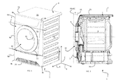
- front loading laundry treatment device includes a casing which encloses an inner compartment comprising the laundry treatment chamber, for example a rotating drum for housing the laundry to be treated and a tub encasing the drum.
- the laundry within the drum is moved by means of the rotation of the drum and by the action of gravity.
- the door assembly of the invention perfectly closes the opening formed in the front wall of the laundry treatment device. No modification has to be made to the laundry treatment device, besides the door assembly itself.
- the invention relates to a method to modify the position of a handle in a door assembly associated to a laundry treatment device, said door assembly including
- a change in handle configuration corresponds either to a change in the opening direction of the door assembly, or to a change in the positioning of the handle within the same side with respect to the vertical axis.
- a laundry treatment device realized according to the present invention are globally indicated with 1 and 100, respectively.
- the laundry treatment devices 1 and 100 are dryers, however the present teaching can be applied to washing machines and washer-dryers as well.
- a horizontal plane is defined (plane (XY) in Figure 1 and 9 ), which is generally the plane on which the bottom wall or basement 74; 174 lies and generally it is also parallel to the top wall 73; 173 of the casing 7; 107 in a mounted configuration.
- the device 1; 100 also extends along a vertical direction denoted with Z.
- the front wall 2; 102 defines a top portion 4a', a middle portion 4a" and a bottom portion 4a"', the terms “top”, “middle” and “bottom” used with reference to the above defined standard standing configuration of the laundry treatment device 1, 100 when in use.
- the opening 4; 104 and thus the door assembly 10; 110 are located in the middle portion 4a" of the front wall 2; 102.
- Laundry treatment device 1; 100 also comprises an electrical motor (not shown) assembly for rotating, on command, revolving drum 3; 103 along its axis inside casing.
- Casing 7; 107 revolving drum 3; 103 and electrical motor are common parts in the technical field and are considered to be known; therefore they will not be described further in details.
- rear frame 5; 105 is indicating in the following the portion of the frame of door assembly 10; 110 a surface of which, called rear surface 5b; 105b, is substantially in contact with casing 7; 107 when the door assembly 10; 110 is in the closed operative position (as shown in fig. 2 or fig. 10 ), while the front frame 6; 106 is defined as the portion of the frame of door assembly 10; 110 a surface of which, called front surface 6a; 106a, is mainly facing the exterior when the door assembly 10; 110 is closed onto casing 7; 107, i.e., it faces a direction opposite to the casing.
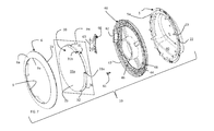
- the aperture 108 in rear frame 105 is closed by a door glass 180 having a bowl shape.
- door glass 180 is made of transparent glass capable of withstanding high temperatures and/or the chemicals which can be present in an embodiment in which the laundry treatment device 100 is a washing machine (embodiment not shown) during washing and/or drying cycles.
- the door glass 180 is assembled together with front and rear frame 106, 105 so as to close aperture 109, 108 preferably in an air-tight manner, so that no fluid can exits laundry treatment device 100 during operation.
- an inner edge or border 9a; 109a, 108a is consequently defined in the front 6; 106 and/or rear frame 105 itself as the edge of the door aperture 9; 109, 108.
- closure plane PB and opening plane PC are substantially parallel to the Z axis.
- a closure plane and/or an opening plane tilted with respect to the Z axis are included as well.
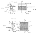
- Figs. 21b, 22b, 23b , 24b and 25b represent a front view of the five different embodiments of the door assembly 10; 110; 10PA, while figs. 21a, 22a, 23a , 24a, and 25a represent a section of the door assembly 10; 110; 10PA of figs. 21b, 22b, 23b , 24b, and 25b , respectively, along a vertical plane passing through the center axis of the respective front view (section along line A-A of the front views).
- the outer edge 11; 111 of the frame is substantially rectangular.
- the section of the front frame along line A-A includes a triangle to the bottom base of which a quarter of circumference is connected.
- the front surface 6a; 106a includes as said a flat surface (a rectangle), therefore the area defined by "putting into contact a candidate front plane PA" onto the front surface of front frame corresponds to the area of the rectangular portion of the front surface itself.
- the plane PA defining an area equal to the area of the flat portion of front surface is the front plane itself.
- the gray area depicted in fig. 21b is therefore the area defined by the single candidate front plane which is also the front plane (or maximal area front plane).
- planes PA and PB define an angle ⁇ herebetween different from 0° and 180°.
- the front frame 6; 106 of this embodiment includes, in a position corresponding to the top most and lower most sides, two prisms "prism 1" and "prism 2" having a triangular base.
- the two triangular prisms have an axis perpendicular to the Z axis and are positioned one on top of the other.
- the base triangle of each prism is a right triangle, which one side lying on the closure plane PB. Therefore, the section of the front frame 6; 106 along the vertical plane defines two triangles, one for each prism, as visible in fig. 23a ; thus a top-most and lower-most triangle are formed.
- the two triangles have different dimensions.
- Five candidate front planes are defined by the present front frame of this embodiment:
- the front frame 6; 106 and the rear frame 5; 105 are coupled one to the other, preferably in a removable manner.
- the coupling is obtained by means of coupling elements 21; 121 and corresponding coupling counter elements 22; 122 formed in the front and rear frame, respectively.
- the insertion of the elements into the counter-elements or vice-versa is obtained with interference so that, when a coupling element is inserted in a coupling counter element (or vice-versa) the removal requires the application of a non-negligible force, so that the possibility of accidental removals is minimized.
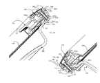
- each coupling element 21 departing from the rear surface 6b of front frame 6 includes a tubular sleeve 91 departing from a pedestal 92.
- the tubular sleeve is not directly connected to the rear surface 6b of front frame 6, but it is positioned on the pedestal 92.
- Coupling counter-elements 22 are realized as through holes on rear frame 5, in which the tubular sleeve 91 of coupling elements 21 can be inserted. Instead of through-holes, coupling counter-elements 22 could include appendices 90 as well.
- Coupling element 121 includes a tubular sleeve 191 departing from a pedestal 192.
- the tubular sleeve is not directly connected to the rear surface 151 of cover ring 150, but it is positioned on the pedestal 192.
- Coupling counter-element 122 departing from the front surface 105a of rear frame 105 includes a tubular sleeve 191 directly departing from the front surface 105a.
- a counter element 22; 122 is present in the rear frame 5; 105 in a bijection correspondence.
- Appendices 190a are located around first element 170 in correspondence of appendices 190 of cover ring 150.
- Pedestals 192a have also different heights, matching the height difference of the pedestals 192, so that each pedestal 192 is in abutment against the inner top surface of pedestal 192a and surfaces 151 and 177 are parallel one to the other.
- coupling elements 21; 121 and coupling counter-elements 22; 122 may have many different other shapes and configurations than the tubular one above described.
- cap element 140 In the embodiment of door assembly 110, with particular reference to figs. 13 , 15 , 16 as well as 14a and 14b, a different element, called cap element 140, than the coupling elements and counter-elements creates the "tilt" between the front plane PA and the closure plane PB, so that they are not parallel.
- the first plane defined by the first surface 141 results substantially parallel to the closure plane PB and the second plane defined by the second surface 142 results substantially parallel to the front plane PA.
- the angle formed between the first and second plane defined by cap element 140 is equal to ⁇ .
- the coupling elements and/or counter-elements 121,122 could have also all the same height, because they are not necessary to form the "tilt", however coupling elements 121 and/or coupling counter-elements 122 with different heights allow a better coupling of components lying on different planes.
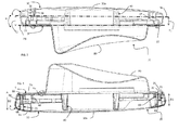
- Handle-carrying element 30 is preferably coupled directly to front frame 6.
- the plate like member 33 thus further includes, extending from its edge 32, an annular flange 36, substantially perpendicular to the plate-like member 33.
- a terminal end of annular flange 36, or at least of portions of the terminal end of annular flange 36, is folded in itself, defining a seat 37 formed by parallel walls defined by the annular flange's fold.
- hinge axis is parallel to the Z axis and centerline C is parallel to the (X,Y) plane, i.e. it is an horizontal axis.
- the lock is configured to avoid opening of the door assembly during operation of the laundry treatment device 1; 100; and to possibly to avoid operation of the device with the door assembly open, for example by issuing a consent signal to an electronic control unit of the device only when the door assembly is closed and/or delay opening of the door assembly after the end of an operation cycle.
- the electromechanical lock is therefore also an interlock.
- hinge 160 and hook or latch 161 are mounted, in a reversible manner, on rear frame 105, at the edge of the same, where the seat 162 is formed.
- the handle-carrying element 30; 130 can be positioned between the front 6; 106 and rear frame 5; 105 at least in two different positions and more preferably in at least four different positions. The difference between one position and the other lies in the handle location: for each position of the handle-carrying element 30; 130 a different location L1, L2, L3, L4 of the handle 31; 131 within the frame is achieved.
- door assembly 110 depicted in figures 19a-19c and 20a-20c , the same description - unless otherwise specified - is applicable also to door assembly 10.
- the cap element 40 is positioned on door frame 5 in such a way that the centering elements 23 are inserted into through-holes 48 of the cap element 40 and the through-holes 44 are aligned with the through-holes defined by the coupling counter-elements 22. Suitable recesses or openings are realized in the edge of rear door frame 5 so that the hinge 60 and the latch or hook 61 can protrude rearward outside the door assembly 10.
- the front frame 6 defines the front plane PA by means of front surface 6a.
- Rear surface 6b defines a plane as well, for example parallel to PA. Therefore any component abutting on such a plane remains, at least for the surface in abutment, parallel to PA.
- the handle-carrying element 30 can define, by means of one of its opposite surfaces, a plane, called handle plane PH, which can be tilted with respect to the closure plane of a different angle than the angle ⁇ present between the front plane PA and the closure plane PB.
- a further angle or tilt has to be realized between the front frame 6 and the handle-carrying element 30, i.e. between the front plane PA and handle plane PH.
- the tilt is determined by the difference in the heights of ridge 143.
Landscapes
- Engineering & Computer Science (AREA)
- Textile Engineering (AREA)
- Main Body Construction Of Washing Machines And Laundry Dryers (AREA)
Priority Applications (5)
| Application Number | Priority Date | Filing Date | Title |
|---|---|---|---|
| PL13182520T PL2843105T3 (pl) | 2013-08-30 | 2013-08-30 | Zespół drzwiowy dla urządzenia do obróbki prania i sposób jego eksploatacji |
| EP13182520.0A EP2843105B1 (fr) | 2013-08-30 | 2013-08-30 | Ensemble de porte pour dispositif de traitement du linge et procédé de fonctionnement |
| AU2014314518A AU2014314518B2 (en) | 2013-08-30 | 2014-07-31 | A door assembly for a laundry treatment device and method of operation |
| CN201480048092.9A CN105492680A (zh) | 2013-08-30 | 2014-07-31 | 用于衣物处理装置的门组件和操作方法 |
| PCT/EP2014/066484 WO2015028246A1 (fr) | 2013-08-30 | 2014-07-31 | Ensemble porte pour un dispositif de traitement de linge, et procédé de fonctionnement |
Applications Claiming Priority (1)
| Application Number | Priority Date | Filing Date | Title |
|---|---|---|---|
| EP13182520.0A EP2843105B1 (fr) | 2013-08-30 | 2013-08-30 | Ensemble de porte pour dispositif de traitement du linge et procédé de fonctionnement |
Publications (2)
| Publication Number | Publication Date |
|---|---|
| EP2843105A1 true EP2843105A1 (fr) | 2015-03-04 |
| EP2843105B1 EP2843105B1 (fr) | 2017-01-18 |
Family
ID=49083568
Family Applications (1)
| Application Number | Title | Priority Date | Filing Date |
|---|---|---|---|
| EP13182520.0A Active EP2843105B1 (fr) | 2013-08-30 | 2013-08-30 | Ensemble de porte pour dispositif de traitement du linge et procédé de fonctionnement |
Country Status (5)
| Country | Link |
|---|---|
| EP (1) | EP2843105B1 (fr) |
| CN (1) | CN105492680A (fr) |
| AU (1) | AU2014314518B2 (fr) |
| PL (1) | PL2843105T3 (fr) |
| WO (1) | WO2015028246A1 (fr) |
Cited By (11)
| Publication number | Priority date | Publication date | Assignee | Title |
|---|---|---|---|---|
| EP3061862A1 (fr) * | 2015-02-27 | 2016-08-31 | Electrolux Appliances Aktiebolag | Sèche-linge |
| CN105908453A (zh) * | 2015-11-02 | 2016-08-31 | Lg电子株式会社 | 衣物处理装置 |
| EP3061863A1 (fr) * | 2015-02-27 | 2016-08-31 | Electrolux Appliances Aktiebolag | Sèche-linge |
| WO2016135285A1 (fr) * | 2015-02-27 | 2016-09-01 | Electrolux Appliances Aktiebolag | Sèche-linge |
| CN105937150A (zh) * | 2016-06-30 | 2016-09-14 | 无锡小天鹅股份有限公司 | 用于衣物处理机的门体组件和具有其的衣物处理机 |
| US9970143B2 (en) | 2015-11-02 | 2018-05-15 | Lg Electronics Inc. | Laundry treating apparatus and method of fabricating a laundry treating apparatus door |
| US10000879B2 (en) | 2015-11-02 | 2018-06-19 | Lg Electronics Inc. | Laundry treating apparatus |
| US10047473B2 (en) | 2015-11-02 | 2018-08-14 | Lg Electronics Inc. | Laundry treating apparatus |
| US10344422B2 (en) | 2015-11-02 | 2019-07-09 | Lg Electronics Inc. | Laundry treating apparatus |
| US10815602B2 (en) | 2015-11-02 | 2020-10-27 | Lg Electronics Inc. | Laundry treating apparatus |
| EP3741905A4 (fr) * | 2018-01-15 | 2021-01-06 | Qingdao Haier Drum Washing Machine Co., Ltd. | Ensemble porte de dispositif de traitement de linge et dispositif de traitement de linge |
Families Citing this family (5)
| Publication number | Priority date | Publication date | Assignee | Title |
|---|---|---|---|---|
| CN206127678U (zh) * | 2016-07-04 | 2017-04-26 | 青岛海尔洗涤电器有限公司 | 非对称玻璃窗的洗衣机门体及洗衣机 |
| JP2018075144A (ja) * | 2016-11-08 | 2018-05-17 | リンナイ株式会社 | 衣類処理機 |
| CN109385851A (zh) * | 2017-08-10 | 2019-02-26 | 青岛海尔滚筒洗衣机有限公司 | 一种滚筒洗衣机及控制方法 |
| CN109554902A (zh) * | 2017-09-27 | 2019-04-02 | 青岛海尔洗衣机有限公司 | 一种观察窗及干衣机 |
| DE102022205165A1 (de) * | 2022-05-24 | 2023-11-30 | BSH Hausgeräte GmbH | Wäschepflegegerät zum Pflegen von Gegenständen |
Citations (5)
| Publication number | Priority date | Publication date | Assignee | Title |
|---|---|---|---|---|
| EP1386994A1 (fr) * | 2002-07-31 | 2004-02-04 | Lg Electronics Inc. | Porte d'une machine à laver à tambour ou d'un sèche-linge |
| EP1466047A1 (fr) | 2002-01-17 | 2004-10-13 | LG Electronics Inc. | Lave-linge et seche-linge equipes d'une porte inclinee |
| EP2147996A1 (fr) * | 2008-07-23 | 2010-01-27 | Electrolux Home Products Corporation N.V. | Ensemble de porte réversible pour machine de traitement du linge à chargement frontal |
| WO2011012593A1 (fr) | 2009-07-31 | 2011-02-03 | BSH Bosch und Siemens Hausgeräte GmbH | Bague avant pour une porte d'appareil électroménager |
| WO2013007507A2 (fr) * | 2011-07-11 | 2013-01-17 | BSH Bosch und Siemens Hausgeräte GmbH | Porte de chargement d'une machine de traitement du linge |
Family Cites Families (4)
| Publication number | Priority date | Publication date | Assignee | Title |
|---|---|---|---|---|
| CN1683695A (zh) * | 2004-04-12 | 2005-10-19 | 乐金电子(天津)电器有限公司 | 滚筒洗衣机的倾斜型门的铰链系统 |
| US8661860B2 (en) * | 2009-07-31 | 2014-03-04 | Bsh Home Appliances Corporation | Door bowl for a household appliance door |
| JP5383878B2 (ja) * | 2011-12-12 | 2014-01-08 | シャープ株式会社 | 洗濯機 |
| DE102012202745B4 (de) * | 2012-02-22 | 2021-06-10 | BSH Hausgeräte GmbH | Tür für ein Haushaltsgerät und Verfahren zum Wechsel eines Türanschlags |
-
2013
- 2013-08-30 EP EP13182520.0A patent/EP2843105B1/fr active Active
- 2013-08-30 PL PL13182520T patent/PL2843105T3/pl unknown
-
2014
- 2014-07-31 CN CN201480048092.9A patent/CN105492680A/zh active Pending
- 2014-07-31 AU AU2014314518A patent/AU2014314518B2/en active Active
- 2014-07-31 WO PCT/EP2014/066484 patent/WO2015028246A1/fr active Application Filing
Patent Citations (5)
| Publication number | Priority date | Publication date | Assignee | Title |
|---|---|---|---|---|
| EP1466047A1 (fr) | 2002-01-17 | 2004-10-13 | LG Electronics Inc. | Lave-linge et seche-linge equipes d'une porte inclinee |
| EP1386994A1 (fr) * | 2002-07-31 | 2004-02-04 | Lg Electronics Inc. | Porte d'une machine à laver à tambour ou d'un sèche-linge |
| EP2147996A1 (fr) * | 2008-07-23 | 2010-01-27 | Electrolux Home Products Corporation N.V. | Ensemble de porte réversible pour machine de traitement du linge à chargement frontal |
| WO2011012593A1 (fr) | 2009-07-31 | 2011-02-03 | BSH Bosch und Siemens Hausgeräte GmbH | Bague avant pour une porte d'appareil électroménager |
| WO2013007507A2 (fr) * | 2011-07-11 | 2013-01-17 | BSH Bosch und Siemens Hausgeräte GmbH | Porte de chargement d'une machine de traitement du linge |
Cited By (18)
| Publication number | Priority date | Publication date | Assignee | Title |
|---|---|---|---|---|
| WO2016135285A1 (fr) * | 2015-02-27 | 2016-09-01 | Electrolux Appliances Aktiebolag | Sèche-linge |
| EP3061862A1 (fr) * | 2015-02-27 | 2016-08-31 | Electrolux Appliances Aktiebolag | Sèche-linge |
| EP3061863A1 (fr) * | 2015-02-27 | 2016-08-31 | Electrolux Appliances Aktiebolag | Sèche-linge |
| US10266983B2 (en) | 2015-11-02 | 2019-04-23 | Lg Electronics Inc. | Laundry treating apparatus |
| US10094063B2 (en) | 2015-11-02 | 2018-10-09 | Lg Electronics Inc. | Laundry treating apparatus and method of fabricating a laundry treating apparatus door |
| USRE49269E1 (en) | 2015-11-02 | 2022-11-01 | Lg Electronics Inc. | Laundry treating apparatus |
| US9970143B2 (en) | 2015-11-02 | 2018-05-15 | Lg Electronics Inc. | Laundry treating apparatus and method of fabricating a laundry treating apparatus door |
| US10000879B2 (en) | 2015-11-02 | 2018-06-19 | Lg Electronics Inc. | Laundry treating apparatus |
| US10006159B2 (en) | 2015-11-02 | 2018-06-26 | Lg Electronics Inc. | Laundry treating apparatus |
| US10047473B2 (en) | 2015-11-02 | 2018-08-14 | Lg Electronics Inc. | Laundry treating apparatus |
| US10815602B2 (en) | 2015-11-02 | 2020-10-27 | Lg Electronics Inc. | Laundry treating apparatus |
| US10161076B2 (en) | 2015-11-02 | 2018-12-25 | Lg Electronics Inc. | Laundry treating apparatus |
| CN105908453A (zh) * | 2015-11-02 | 2016-08-31 | Lg电子株式会社 | 衣物处理装置 |
| US10344422B2 (en) | 2015-11-02 | 2019-07-09 | Lg Electronics Inc. | Laundry treating apparatus |
| US10711389B2 (en) | 2015-11-02 | 2020-07-14 | Lg Electronics Inc. | Door hinge of a laundry treating apparatus |
| CN105937150A (zh) * | 2016-06-30 | 2016-09-14 | 无锡小天鹅股份有限公司 | 用于衣物处理机的门体组件和具有其的衣物处理机 |
| CN105937150B (zh) * | 2016-06-30 | 2018-04-24 | 无锡小天鹅股份有限公司 | 用于衣物处理机的门体组件和具有其的衣物处理机 |
| EP3741905A4 (fr) * | 2018-01-15 | 2021-01-06 | Qingdao Haier Drum Washing Machine Co., Ltd. | Ensemble porte de dispositif de traitement de linge et dispositif de traitement de linge |
Also Published As
| Publication number | Publication date |
|---|---|
| EP2843105B1 (fr) | 2017-01-18 |
| WO2015028246A1 (fr) | 2015-03-05 |
| AU2014314518A1 (en) | 2016-03-10 |
| AU2014314518B2 (en) | 2019-01-17 |
| PL2843105T3 (pl) | 2017-07-31 |
| CN105492680A (zh) | 2016-04-13 |
Similar Documents
| Publication | Publication Date | Title |
|---|---|---|
| EP2843105B1 (fr) | Ensemble de porte pour dispositif de traitement du linge et procédé de fonctionnement | |
| AU2014314517B2 (en) | Door assembly for a laundry treatment device | |
| JP4636148B2 (ja) | ドラム式洗濯機 | |
| JP5618517B2 (ja) | 電気洗濯機 | |
| US8127464B2 (en) | Front ring for a household appliance door | |
| EP3181750A1 (fr) | Dispositif de traitement du linge avec ensemble de porte | |
| AU2014314511B2 (en) | Door assembly for a laundry treatment device | |
| KR20030060557A (ko) | 드럼세탁기의 도어 | |
| AU2014314512B2 (en) | A door assembly for a laundry treatment device and method of operation | |
| EP2871279B1 (fr) | Machine à laver et procédé de fabrication de sa porte | |
| AU2017362549B2 (en) | A door assembly for a laundry treatment machine | |
| JP2009213804A (ja) | ドラム式洗濯機 | |
| EP3323928B1 (fr) | Ensemble porte pour machine de traitement de linge et procédé pour modifier la position d'une poignée dans ledit ensemble porte | |
| KR200395273Y1 (ko) | 세탁기의 전면부 구조 | |
| EP2929077B1 (fr) | Dispositif de traitement du linge avec ensemble de porte | |
| JP5707523B2 (ja) | 電気洗濯機 | |
| EP3323927B1 (fr) | Ensemble porte pour machine de traitement de linge | |
| JP6177822B2 (ja) | 電気洗濯機 | |
| JP6295356B2 (ja) | 電気洗濯機 |
Legal Events
| Date | Code | Title | Description |
|---|---|---|---|
| 17P | Request for examination filed |
Effective date: 20130830 |
|
| AK | Designated contracting states |
Kind code of ref document: A1 Designated state(s): AL AT BE BG CH CY CZ DE DK EE ES FI FR GB GR HR HU IE IS IT LI LT LU LV MC MK MT NL NO PL PT RO RS SE SI SK SM TR |
|
| AX | Request for extension of the european patent |
Extension state: BA ME |
|
| PUAI | Public reference made under article 153(3) epc to a published international application that has entered the european phase |
Free format text: ORIGINAL CODE: 0009012 |
|
| R17P | Request for examination filed (corrected) |
Effective date: 20150904 |
|
| RBV | Designated contracting states (corrected) |
Designated state(s): AL AT BE BG CH CY CZ DE DK EE ES FI FR GB GR HR HU IE IS IT LI LT LU LV MC MK MT NL NO PL PT RO RS SE SI SK SM TR |
|
| GRAP | Despatch of communication of intention to grant a patent |
Free format text: ORIGINAL CODE: EPIDOSNIGR1 |
|
| INTG | Intention to grant announced |
Effective date: 20160928 |
|
| GRAS | Grant fee paid |
Free format text: ORIGINAL CODE: EPIDOSNIGR3 |
|
| GRAA | (expected) grant |
Free format text: ORIGINAL CODE: 0009210 |
|
| AK | Designated contracting states |
Kind code of ref document: B1 Designated state(s): AL AT BE BG CH CY CZ DE DK EE ES FI FR GB GR HR HU IE IS IT LI LT LU LV MC MK MT NL NO PL PT RO RS SE SI SK SM TR |
|
| REG | Reference to a national code |
Ref country code: GB Ref legal event code: FG4D |
|
| REG | Reference to a national code |
Ref country code: CH Ref legal event code: EP |
|
| REG | Reference to a national code |
Ref country code: AT Ref legal event code: REF Ref document number: 862989 Country of ref document: AT Kind code of ref document: T Effective date: 20170215 |
|
| REG | Reference to a national code |
Ref country code: IE Ref legal event code: FG4D |
|
| REG | Reference to a national code |
Ref country code: DE Ref legal event code: R096 Ref document number: 602013016657 Country of ref document: DE |
|
| REG | Reference to a national code |
Ref country code: NL Ref legal event code: MP Effective date: 20170118 |
|
| REG | Reference to a national code |
Ref country code: LT Ref legal event code: MG4D |
|
| REG | Reference to a national code |
Ref country code: AT Ref legal event code: MK05 Ref document number: 862989 Country of ref document: AT Kind code of ref document: T Effective date: 20170118 |
|
| PG25 | Lapsed in a contracting state [announced via postgrant information from national office to epo] |
Ref country code: NL Free format text: LAPSE BECAUSE OF FAILURE TO SUBMIT A TRANSLATION OF THE DESCRIPTION OR TO PAY THE FEE WITHIN THE PRESCRIBED TIME-LIMIT Effective date: 20170118 |
|
| PG25 | Lapsed in a contracting state [announced via postgrant information from national office to epo] |
Ref country code: HR Free format text: LAPSE BECAUSE OF FAILURE TO SUBMIT A TRANSLATION OF THE DESCRIPTION OR TO PAY THE FEE WITHIN THE PRESCRIBED TIME-LIMIT Effective date: 20170118 Ref country code: FI Free format text: LAPSE BECAUSE OF FAILURE TO SUBMIT A TRANSLATION OF THE DESCRIPTION OR TO PAY THE FEE WITHIN THE PRESCRIBED TIME-LIMIT Effective date: 20170118 Ref country code: NO Free format text: LAPSE BECAUSE OF FAILURE TO SUBMIT A TRANSLATION OF THE DESCRIPTION OR TO PAY THE FEE WITHIN THE PRESCRIBED TIME-LIMIT Effective date: 20170418 Ref country code: LT Free format text: LAPSE BECAUSE OF FAILURE TO SUBMIT A TRANSLATION OF THE DESCRIPTION OR TO PAY THE FEE WITHIN THE PRESCRIBED TIME-LIMIT Effective date: 20170118 Ref country code: IS Free format text: LAPSE BECAUSE OF FAILURE TO SUBMIT A TRANSLATION OF THE DESCRIPTION OR TO PAY THE FEE WITHIN THE PRESCRIBED TIME-LIMIT Effective date: 20170518 Ref country code: GR Free format text: LAPSE BECAUSE OF FAILURE TO SUBMIT A TRANSLATION OF THE DESCRIPTION OR TO PAY THE FEE WITHIN THE PRESCRIBED TIME-LIMIT Effective date: 20170419 |
|
| PG25 | Lapsed in a contracting state [announced via postgrant information from national office to epo] |
Ref country code: RS Free format text: LAPSE BECAUSE OF FAILURE TO SUBMIT A TRANSLATION OF THE DESCRIPTION OR TO PAY THE FEE WITHIN THE PRESCRIBED TIME-LIMIT Effective date: 20170118 Ref country code: AT Free format text: LAPSE BECAUSE OF FAILURE TO SUBMIT A TRANSLATION OF THE DESCRIPTION OR TO PAY THE FEE WITHIN THE PRESCRIBED TIME-LIMIT Effective date: 20170118 Ref country code: PT Free format text: LAPSE BECAUSE OF FAILURE TO SUBMIT A TRANSLATION OF THE DESCRIPTION OR TO PAY THE FEE WITHIN THE PRESCRIBED TIME-LIMIT Effective date: 20170518 Ref country code: ES Free format text: LAPSE BECAUSE OF FAILURE TO SUBMIT A TRANSLATION OF THE DESCRIPTION OR TO PAY THE FEE WITHIN THE PRESCRIBED TIME-LIMIT Effective date: 20170118 Ref country code: SE Free format text: LAPSE BECAUSE OF FAILURE TO SUBMIT A TRANSLATION OF THE DESCRIPTION OR TO PAY THE FEE WITHIN THE PRESCRIBED TIME-LIMIT Effective date: 20170118 Ref country code: BG Free format text: LAPSE BECAUSE OF FAILURE TO SUBMIT A TRANSLATION OF THE DESCRIPTION OR TO PAY THE FEE WITHIN THE PRESCRIBED TIME-LIMIT Effective date: 20170418 Ref country code: LV Free format text: LAPSE BECAUSE OF FAILURE TO SUBMIT A TRANSLATION OF THE DESCRIPTION OR TO PAY THE FEE WITHIN THE PRESCRIBED TIME-LIMIT Effective date: 20170118 |
|
| REG | Reference to a national code |
Ref country code: DE Ref legal event code: R097 Ref document number: 602013016657 Country of ref document: DE |
|
| PG25 | Lapsed in a contracting state [announced via postgrant information from national office to epo] |
Ref country code: CZ Free format text: LAPSE BECAUSE OF FAILURE TO SUBMIT A TRANSLATION OF THE DESCRIPTION OR TO PAY THE FEE WITHIN THE PRESCRIBED TIME-LIMIT Effective date: 20170118 Ref country code: RO Free format text: LAPSE BECAUSE OF FAILURE TO SUBMIT A TRANSLATION OF THE DESCRIPTION OR TO PAY THE FEE WITHIN THE PRESCRIBED TIME-LIMIT Effective date: 20170118 Ref country code: EE Free format text: LAPSE BECAUSE OF FAILURE TO SUBMIT A TRANSLATION OF THE DESCRIPTION OR TO PAY THE FEE WITHIN THE PRESCRIBED TIME-LIMIT Effective date: 20170118 Ref country code: SK Free format text: LAPSE BECAUSE OF FAILURE TO SUBMIT A TRANSLATION OF THE DESCRIPTION OR TO PAY THE FEE WITHIN THE PRESCRIBED TIME-LIMIT Effective date: 20170118 |
|
| PLBE | No opposition filed within time limit |
Free format text: ORIGINAL CODE: 0009261 |
|
| STAA | Information on the status of an ep patent application or granted ep patent |
Free format text: STATUS: NO OPPOSITION FILED WITHIN TIME LIMIT |
|
| PG25 | Lapsed in a contracting state [announced via postgrant information from national office to epo] |
Ref country code: SM Free format text: LAPSE BECAUSE OF FAILURE TO SUBMIT A TRANSLATION OF THE DESCRIPTION OR TO PAY THE FEE WITHIN THE PRESCRIBED TIME-LIMIT Effective date: 20170118 Ref country code: DK Free format text: LAPSE BECAUSE OF FAILURE TO SUBMIT A TRANSLATION OF THE DESCRIPTION OR TO PAY THE FEE WITHIN THE PRESCRIBED TIME-LIMIT Effective date: 20170118 |
|
| 26N | No opposition filed |
Effective date: 20171019 |
|
| PG25 | Lapsed in a contracting state [announced via postgrant information from national office to epo] |
Ref country code: SI Free format text: LAPSE BECAUSE OF FAILURE TO SUBMIT A TRANSLATION OF THE DESCRIPTION OR TO PAY THE FEE WITHIN THE PRESCRIBED TIME-LIMIT Effective date: 20170118 |
|
| REG | Reference to a national code |
Ref country code: CH Ref legal event code: PL |
|
| PG25 | Lapsed in a contracting state [announced via postgrant information from national office to epo] |
Ref country code: MC Free format text: LAPSE BECAUSE OF FAILURE TO SUBMIT A TRANSLATION OF THE DESCRIPTION OR TO PAY THE FEE WITHIN THE PRESCRIBED TIME-LIMIT Effective date: 20170118 |
|
| GBPC | Gb: european patent ceased through non-payment of renewal fee |
Effective date: 20170830 |
|
| PG25 | Lapsed in a contracting state [announced via postgrant information from national office to epo] |
Ref country code: CH Free format text: LAPSE BECAUSE OF NON-PAYMENT OF DUE FEES Effective date: 20170831 Ref country code: LI Free format text: LAPSE BECAUSE OF NON-PAYMENT OF DUE FEES Effective date: 20170831 |
|
| REG | Reference to a national code |
Ref country code: FR Ref legal event code: ST Effective date: 20180430 |
|
| REG | Reference to a national code |
Ref country code: IE Ref legal event code: MM4A |
|
| REG | Reference to a national code |
Ref country code: BE Ref legal event code: MM Effective date: 20170831 |
|
| PG25 | Lapsed in a contracting state [announced via postgrant information from national office to epo] |
Ref country code: LU Free format text: LAPSE BECAUSE OF NON-PAYMENT OF DUE FEES Effective date: 20170830 |
|
| PG25 | Lapsed in a contracting state [announced via postgrant information from national office to epo] |
Ref country code: GB Free format text: LAPSE BECAUSE OF NON-PAYMENT OF DUE FEES Effective date: 20170830 Ref country code: IE Free format text: LAPSE BECAUSE OF NON-PAYMENT OF DUE FEES Effective date: 20170830 |
|
| PG25 | Lapsed in a contracting state [announced via postgrant information from national office to epo] |
Ref country code: FR Free format text: LAPSE BECAUSE OF NON-PAYMENT OF DUE FEES Effective date: 20170831 Ref country code: BE Free format text: LAPSE BECAUSE OF NON-PAYMENT OF DUE FEES Effective date: 20170831 |
|
| PG25 | Lapsed in a contracting state [announced via postgrant information from national office to epo] |
Ref country code: MT Free format text: LAPSE BECAUSE OF NON-PAYMENT OF DUE FEES Effective date: 20170830 |
|
| PG25 | Lapsed in a contracting state [announced via postgrant information from national office to epo] |
Ref country code: HU Free format text: LAPSE BECAUSE OF FAILURE TO SUBMIT A TRANSLATION OF THE DESCRIPTION OR TO PAY THE FEE WITHIN THE PRESCRIBED TIME-LIMIT; INVALID AB INITIO Effective date: 20130830 |
|
| PG25 | Lapsed in a contracting state [announced via postgrant information from national office to epo] |
Ref country code: CY Free format text: LAPSE BECAUSE OF FAILURE TO SUBMIT A TRANSLATION OF THE DESCRIPTION OR TO PAY THE FEE WITHIN THE PRESCRIBED TIME-LIMIT Effective date: 20170118 |
|
| PG25 | Lapsed in a contracting state [announced via postgrant information from national office to epo] |
Ref country code: MK Free format text: LAPSE BECAUSE OF FAILURE TO SUBMIT A TRANSLATION OF THE DESCRIPTION OR TO PAY THE FEE WITHIN THE PRESCRIBED TIME-LIMIT Effective date: 20170118 |
|
| PG25 | Lapsed in a contracting state [announced via postgrant information from national office to epo] |
Ref country code: TR Free format text: LAPSE BECAUSE OF FAILURE TO SUBMIT A TRANSLATION OF THE DESCRIPTION OR TO PAY THE FEE WITHIN THE PRESCRIBED TIME-LIMIT Effective date: 20170118 |
|
| PG25 | Lapsed in a contracting state [announced via postgrant information from national office to epo] |
Ref country code: AL Free format text: LAPSE BECAUSE OF FAILURE TO SUBMIT A TRANSLATION OF THE DESCRIPTION OR TO PAY THE FEE WITHIN THE PRESCRIBED TIME-LIMIT Effective date: 20170118 |
|
| P01 | Opt-out of the competence of the unified patent court (upc) registered |
Effective date: 20230625 |
|
| PGFP | Annual fee paid to national office [announced via postgrant information from national office to epo] |
Ref country code: IT Payment date: 20230822 Year of fee payment: 11 |
|
| PGFP | Annual fee paid to national office [announced via postgrant information from national office to epo] |
Ref country code: PL Payment date: 20230818 Year of fee payment: 11 Ref country code: DE Payment date: 20230828 Year of fee payment: 11 |