EP2842766B1 - Fahrzeugreifen - Google Patents
Fahrzeugreifen Download PDFInfo
- Publication number
- EP2842766B1 EP2842766B1 EP14170139.1A EP14170139A EP2842766B1 EP 2842766 B1 EP2842766 B1 EP 2842766B1 EP 14170139 A EP14170139 A EP 14170139A EP 2842766 B1 EP2842766 B1 EP 2842766B1
- Authority
- EP
- European Patent Office
- Prior art keywords
- hatching
- elevations
- portions
- tyre according
- ridges
- Prior art date
- Legal status (The legal status is an assumption and is not a legal conclusion. Google has not performed a legal analysis and makes no representation as to the accuracy of the status listed.)
- Active
Links
Images
Classifications
-
- B—PERFORMING OPERATIONS; TRANSPORTING
- B60—VEHICLES IN GENERAL
- B60C—VEHICLE TYRES; TYRE INFLATION; TYRE CHANGING; CONNECTING VALVES TO INFLATABLE ELASTIC BODIES IN GENERAL; DEVICES OR ARRANGEMENTS RELATED TO TYRES
- B60C13/00—Tyre sidewalls; Protecting, decorating, marking, or the like, thereof
- B60C13/001—Decorating, marking or the like
Definitions
- the invention relates to a vehicle tire with a decorative sowandschraffur of a plurality of juxtaposed surveys, which form a base hatch, wherein formed by surveys from the base hatch at consistently large angles deflected portions at least a localized hatching area, the deflected portions by again, in accordance with at high angles, at least one further hatching area, wherein the elevations in all hatching areas are portions in the course of elevations from the base hatching.
- a vehicle tire is known in which the elevations, which form hatching surfaces, are arranged in a fan-like converging in the radial direction
- a vehicle tire of the aforementioned type is known in which the elevations in the hatching surfaces extend to each other in a zig-zag shape and in a simple manner at different angles to the radial direction, wherein the hatching surfaces are each concentric with the tire axis extending annular segments.
- the The iswandschraffur has hatching surfaces, which are each formed by at different angles to the radial direction extending elevations, however, which have no connections from hatching area to hatching area.
- a Thiswandschraffur with a running in the radial direction base hatching, in which the elevations in short sections wavy or zigzag-shaped, so that along the wave or zigzag-shaped sections a decorative element, a letter or the like is modeled .
- Hatching of side-by-side small bumps used to structure the surfaces of tire sidewalls has the primary purpose of enhancing the contrast with the smooth surface areas of the sidewalls so as to more clearly highlight, for example, the signatures.
- hatching surfaces can mask construction-related unevennesses in the tire sidewalls.
- the technical necessity of hatching on sidewalls, which is therefore consistently given, can also be used creatively, whereby there is an increasing need to use hatching for the individualization of the sidewall designs and thus of the vehicle tires, wherein three-dimensional designs are also desired.
- the latter is not possible because of the risk of uneven distribution of the rubber material, which would lead to disturbance of the uniformity of the tire.
- the usual bumps forming hatching surfaces are limited to a height of 0.3 mm for hatching in car tires and to a height of 0.6 mm for bumps on smooth-surfaced areas.
- the object of the invention is to be able to execute hatching or hatching surfaces in the sidewall of a tire in such a way that individualization of the sidewall decoration and achievement of three-dimensional effects are possible.
- the object is achieved according to the invention in that the base hatch is deflected from its basic orientation so that the hatching surfaces formed simulate three-dimensional shapes or bodies that interrupt the base hatching. According to the invention, therefore, a simple base hatch is deflected from its basic orientation to form hatch areas, the three-dimensional shapes or bodies.
- This three-dimensional effect can be explained by the following example: If light lines are projected onto a three-dimensionally deformed surface, they are influenced and deflected by the shape of the surface in its course.
- the elevations in the base hatch are substantially rectilinear or even rectilinear, and in particular also parallel or substantially parallel to one another. In this way, an inconspicuous base hatch is created, which recedes from the hatching areas in which the deflected portions of the elevations extend from the base hatch.
- the Elevations in the base hatch may also be arcuately curved or wavy.
- the portions deflected by the elevations of the base hatch, which form the hatching surfaces may be rectilinear or substantially rectilinear, or alternatively also arcuate, undulating and the like. It is advantageous if the deflected sections run parallel or substantially parallel to one another. Depending on how large the deflection angle is, the deflected sections have different mutual distances in the individual hatching surfaces. Thus, in a hatching area of a decorative element, the deflected sections can have a significantly greater distance from each other than the deflected sections in another hatching area of the same decorative element. The mutual distances are in each case the same size. Through these measures, special three-dimensional effects can be achieved and a variety of individual, three-dimensional design elements can be created.
- the design or decorative elements can be composed of hatching surfaces that simulate the lateral surfaces of geometric bodies, for example pyramidal surfaces. Such decorative elements give the impression of three-dimensional, positioned on the side wall bodies.
- the deflection angle is at least 5 °.
- the deflection angle can also be significantly greater, for example he can Exceed 90 °.
- at least five, preferably at least ten, elevations per hatching area are provided.
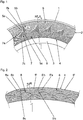
- Fig. 1 to Fig. 4 show projected in the plane representations of a side wall or hatching areas, whereby the slight curvature of the tire sidewall is disregarded. Only in Fig. 1 Figure 3 schematically shows a peripheral portion of the side view of a pneumatic vehicle tire having a tread outlet 1, a sidewall 2 and an outer bead portion 3 which is at least partially covered by the rim mounted on a rim.
- the prescribed information such as the dimensions, the speed index, the manufacturer, the intended use (summer / winter tires) and the like are given.
- This information is provided on smooth surface areas and are formed of raised elements in the rubber material of the side wall.
- Hatching refers to decors in the sidewall of pneumatic vehicle tires, which in each case consist of a multiplicity of elevations which are in particular triangular in cross-section and run side by side and in particular parallel or substantially parallel to one another.
- the height of these elevations is 0.2 mm to 1 mm, in car tires usually in the order of 0.3 mm and in truck tires usually from 0.5 mm to 0.8 mm.
- At least within a certain hatching area or a hatching area all elevations have matching heights. It can be provided to assemble individual hatching areas or hatching areas from elevations which have a different height than elevations of further hatching areas provided.
- the mutual spacing of the bumps in different hatching areas or hatching areas may be different.
- the width of the elevations at their base corresponds in particular substantially to their height, but may also be slightly larger or smaller.
- a side wall decor 4 which has a base hatch 6, which consists of a plurality of rectilinear elevations 5, which extend to the radial direction R at an acute angle ⁇ , which in this embodiment in particular ⁇ 45 °, and preferably 20 ° to 30 °. Due to the circular ring shape of the side wall 2, the mutual distance of the elevations 5 at the radially inner edge of the base hatch 6 is smaller than at the radially outer edge of the base hatch 6. The elevations 5 therefore do not run exactly parallel to each other.
- the basic hatching 6 is interrupted by arranged in a row, having a triangular outline decorative elements 7, which are each composed of three triangular hatching surfaces 7a, 7b and 7c, which are formed by a deflection of a number of elevations 5 of the base hatch 6.
- Each of the differently sized hatching areas 7a, 7b and 7c has the shape of an unequal triangle.
- the deflection of the elevations 5 from the base hatching 6 takes place deliberately such that the hatching surfaces 7a, 7b and 7c are formed. For example, in the Hatching surface 7a portions 5a of the elevations 5, which are deflected at an angle from the course of the elevations 5 in the base hatching 6, which is substantially 90 °.
- the portions 5a of the elevations 5 in the hatching area 7a have a substantially greater mutual distance than the elevations 5 in the base hatching 6.
- the portions 5b of the elevations 5 in the hatching area 7b arise in part by deflecting elevations 5 of the base hatching 6 and Part by deflection of the sections 5a from the hatching surface 7a.
- the portions 5c in the hatching area 7c are formed by deflecting the portions 5a and 5b from the hatching areas 7a and 7b.
- the sections 5b and 5c in the hatching areas 7b and 7c have a smaller mutual distance than the elevations 5 in the base hatching 6.
- the total number of elevations 5, since they are only deflected remains constant. Due to the special distraction of sections of the linear base hatching 6 creates the impression of three-dimensional bodies, here three-sided pyramids, which are located on the basis of the cross-hatch surface and this "deform". The invention therefore makes it possible to simulate three-dimensional structures.
- the side wall decor 4 likewise has a base hatching 6 'of a multiplicity of elevations 5' running essentially parallel to one another and at an angle ⁇ of approximately 30 ° to the radial direction R.
- a base hatching 6 'of a multiplicity of elevations 5' running essentially parallel to one another and at an angle ⁇ of approximately 30 ° to the radial direction R.
- crescent-shaped decorative elements 8 are formed in the base hatch 6 '.
- Each three crescent-shaped decorative elements 8 are arranged in a group, such that the impression arises that the decorative elements 8 are partially "one above the other".
- Each crescent-shaped decorative element 8 consists of three hatching surfaces 8a, 8b and 8c, each of which is also designed essentially crescent-shaped, with the hatching surfaces 8a and 8c jointly enclosing the hatching surface 8b.
- the hatching area 8b there are sections 5'b of the elevations 5 'which run parallel to the elevations 5' but with a lateral offset to them.
- the sections 5'a and 5'c of the elevations 5 'in the hatching areas 8a and 8c are each deflected at different angles from the elevations 5' in the base hatching 6 ', extend substantially parallel to one another within the hatching areas 8a and 8c, and thus, that, depending on the size of the Distortion angles that portions 5'a and 5'c in the hatching areas 8a and 8c are less than or larger than the elevations 5 'in the base hatching 6.
- This embodiment shows that the simulated three-dimensional crescent-shaped decor elements 8 intersect each other can, so that here a special three-dimensional effect is conveyed.
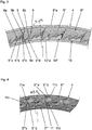
- Fig. 3 shows an embodiment in which a base hatch 6 "is provided, which starts at the radially outer edge region of the side wall decoration 4 and is composed of elevations 5", which are parallel to each other and oriented at an angle ⁇ to the radial direction R, which in the shown Embodiment> 45 ° and is on the order of 70 °.
- All hatching surfaces 9a, 9b, 9c and 9d are formed by sections 5 “a, 5" b, 5 “c, 5" d of the elevations 5 "deflected by the rectilinear course of the elevations 5" or by deflected sections 5 “a, Connect 5 “b, 5" c, 5 “d to each other.
- the sections 5 “a, 5" b, 5 “c, 5" d are for the most part also deflected and merge into elevations 10 "of a border hatch 10 which forms substantially triangular flanks of the simulated mountains 9.
- the elevations 10" run below one substantially smaller angle to the radial direction R than the elevations 5 "in the base hatch 6".
- Both the elevations 5 “of the base hatching 6" and the elevations 10 “of the border hatch 10 have narrow edge sections 5" e, 10 "a, which are formed by deflected sections of the elevations 5" and 10 "extending essentially in the radial direction R These underline the three-dimensional effect produced by the hatching surfaces 9a, 9b, 9c and 9d and the marginal hatching 10.
- the side wall decor 4 has a base hatching 6 '", which is composed of a plurality of elevations 5'" which are substantially parallel to each other and oriented at an angle ⁇ in the order of 45 ° to the radial direction R.
- a base hatching 6 ' which is composed of a plurality of elevations 5'" which are substantially parallel to each other and oriented at an angle ⁇ in the order of 45 ° to the radial direction R.
- the sections 5 '" a and 5'"b of FIG Elevations 5 '"in the hatching surfaces 11a and 11b are curved, in particular approximately arcuately curved, and pass through corresponding deflections into the sections 5"' c and 5 "'of the elevations 5'" in the hatching areas 11c and 11d a special three-dimensional effect by arcuate or in plan view curved portions extending 5 '"a and 5'" b of the elevations 5 '".
- the invention makes it possible to simulate a multiplicity of three-dimensional structures or bodies by deflecting elevations of a hatching with the formation of defined hatching areas.
- the size ratios and distances between the elevations and their actual height are matched to the simulated three-dimensional designs.
Landscapes
- Engineering & Computer Science (AREA)
- Mechanical Engineering (AREA)
- Tires In General (AREA)
Description
- Die Erfindung betrifft einen Fahrzeugreifen mit einer dekorativen Seitenwandschraffur aus einer Vielzahl von nebeneinander verlaufenden Erhebungen, die eine Basisschraffur bilden, wobei von Erhebungen aus der Basisschraffur unter übereinstimmend großen Winkeln abgelenkte Abschnitte zumindest eine örtlich begrenzte Schraffurfläche bilden, wobei die abgelenkten Abschnitte durch nochmaliges, unter übereinstimmend großen Winkeln erfolgtes Ablenken in zumindest eine weitere Schraffurfläche übergehen, wobei die Erhebungen in sämtlichen Schraffurflächen Abschnitte im Verlauf von Erhebungen aus der Basisschraffur sind.
- National oder EU-weit geltende Vorschriften erfordern es, an den Seitenwänden von Reifen bestimmte Zeichen bzw. Bezeichnungen anzubringen. Zu diesen Bezeichnungen gehören sowohl bei PKW- als auch bei LKW-Reifen Dimensionsbezeichnungen, Angaben über die Bauart des Reifens, gegebenenfalls Safety Warnings und dergleichen. Bei manchen dieser Angaben ist die Schriftgröße, zum Teil ist sogar die Position auf der Seitenwand vorgeschrieben. Trotzdem verbleiben auf den Seitenwänden eines Reifens freie Flächen, die für gestalterische Maßnahmen zur Verfügung stehen. Solche gestalterischen Maßnahmen waren immer wieder Gegenstand von Patentanmeldungen und Patenten. So ist beispielsweise aus der
DE 4111345 A1 ein Fahrzeugreifen bekannt, bei dem die Erhebungen, welche Schraffurflächen bilden, in radialer Richtung fächerartig zusammenlaufend angeordnet sind
Aus der gattungsbildendenJP H11 198614 A US 2010/0258231 A1 bekannt. Die Seitenwandschraffur weist Schraffurflächen auf, welche jeweils von unter unterschiedlichen Winkeln zur radialen Richtung verlaufenden Erhebungen gebildet sind, die jedoch von Schraffurfläche zu Schraffurfläche keine Verbindungen aufweisen. Aus derUS 2011/0139326 A1 ist eine Seitenwandschraffur mit einer in radialer Richtung verlaufenden Basisschraffur bekannt, bei welcher die Erhebungen in kurzen Abschnitten wellen- oder zick-zack-förmig verlaufen, sodass entlang der wellen- oder zick-zack-förmigen Abschnitte ein Dekorelement, ein Buchstabe oder dergleichen nachgebildet wird.
Schraffuren aus nebeneinander verlaufenden kleinen Erhebungen, die zur Strukturierung der Oberflächen von Reifenseitenwänden verwendet werden, haben in erster Linie die Aufgabe, den Kontrast zu den glatten Flächenbereichen der Seitenwände zu verstärken, um derart beispielsweise die Schriftzüge deutlicher hervorzuheben. Darüber hinaus lassen sich mit Schraffurflächen konstruktionsbedingte Unebenheiten in der Reifenseitenwänden kaschieren. Die daher durchwegs gegebene technische Notwendigkeit von Schraffuren auf Seitenwänden lässt sich auch gestalterisch nutzen, wobei zunehmend das Bedürfnis besteht, Schraffuren zur Individualisierung der Seitenwanddesigns und damit der Fahrzeugreifen heranzuziehen, wobei auch dreidimensionale Gestaltungen erwünscht sind. Letzteres ist jedoch nicht möglich, da dadurch die Gefahr einer ungleichen Verteilung des Gummimaterials entsteht, welche zur Störung der Uniformity des Reifens führen würde. An den Reifenseitenwänden werden daher die üblichen Erhebungen, die Schraffurflächen bilden, bei PKW-Reifen auf eine Höhe von 0,3 mm für Schraffuren und auf eine Höhe von 0,6 mm für Erhebungen an glattflächigen Bereichen beschränkt. - Der Erfindung liegt die Aufgabe zugrunde, Schraffuren bzw. Schraffurflächen in der Seitenwand eines Reifens derart ausführen zu können, dass eine Individualisierung des Seitenwanddekors und das Erzielen von dreidimensionalen Effekten möglich sind.
Gelöst wird die gestellte Aufgabe erfindungsgemäß dadurch, dass die Basisschraffur derart von ihrer Grundausrichtung abgelenkt ist, dass die gebildeten Schraffurflächen dreidimensionale Formen bzw. Körpern simulieren, welche die Basisschraffur unterbrechen.
Gemäß der Erfindung wird daher eine einfache Basisschraffur so von ihrer Grundausrichtung abgelenkt, dass Schraffurflächen gebildet werden, die dreidimensionalen Formen bzw. Körpern. Dieser dreidimensionale Effekt lässt sich durch folgendes Beispiel erklären: Projiziert man Lichtlinien auf eine dreidimensional verformte Fläche, so werden diese durch die jeweilige Form der Fläche in ihrem Verlauf beeinflusst und abgelenkt. Die entsprechenden Formen werden daher viel deutlicher erkennbar als durch ihre an sich vorhandene Dreidimensionalität. Diese Methode wird beispielsweise zur Erkennung von Dellen und Beulen auf Autoblechen verwendet. Gedanklich können nun diese Lichtlinien durch Schraffurlinien (Erhebungen) ersetzt werden, wobei bei der Erfindung die Ablenkung nur simuliert ist. Es gibt keine tatsächlich dreidimensional verformte Fläche, aber die Ablenkung der Schraffurlinien ist trotzdem vorhanden. Die Erfindung gestattet es daher prinzipiell, nahezu jede dreidimensionale Geometrie bzw. beliebige dreidimensionale Körper vorzutäuschen. Damit eröffnet die Erfindung eine Vielzahl von Möglichkeiten, individuelle, dreidimensional wirkende Designelemente an Seitenwänden von Fahrzeugreifen anzubringen.
Bei einer bevorzugten Ausführungsforrn der Erfindung verlaufen die Erhebungen in der Basisschraffur im Wesentlichen geradlinig oder überhaupt geradlinig und insbesondere auch parallel bzw. im Wesentlichen parallel zueinander. Auf diese Weise wird eine unauffällige Basisschraffur geschaffen, die gegenüber den Schraffurflächen, in welchen die abgelenkten Abschnitte der Erhebungen aus der Basisschraffur verlaufen, zurücktritt. Die Erhebungen in der Basisschraffur können ferner auch bogenförmig gekrümmt oder in Wellenform verlaufen. - Auch die von den Erhebungen der Basisschraffur abgelenkten Abschnitte, welche die Schraffurflächen bilden, können geradlinig oder im Wesentlichen geradlinig oder alternativ auch bogenförmig, wellenförmig und dergleichen verlaufen. Vorteilhaft ist es, wenn die abgelenkten Abschnitte parallel bzw. im Wesentlichen parallel zueinander verlaufen. Je nachdem, wie groß der Ablenkungswinkel ist, weisen die abgelenkten Abschnitte in den einzelnen Schraffurflächen unterschiedliche gegenseitige Abstände auf. So können in einer Schraffurfläche eines Dekorelementes die abgelenkten Abschnitte zueinander einen wesentlich größeren Abstand aufweisen, als die abgelenkten Abschnitte in einer anderen Schraffurfläche des gleichen Dekorelementes. Die gegenseitigen Abstände sind insbesondere jeweils gleich groß. Durch diese Maßnahmen können besondere dreidimensionale Effekte erzielt werden und es kann eine Vielfalt an individuellen, dreidimensional wirkenden Designelementen kreiert werden.
- Die Design- bzw. Dekorelemente können sich aus Schraffurflächen zusammensetzen, die Mantelflächen geometrischer Körper, beispielsweise Pyramidenflächen, simulieren. Solche Dekorelemente vermitteln den Eindruck von dreidimensionalen, auf der Seitenwand positionierten Körpern.
- Gut erkennbar sind erwähnten Effekte, wenn die Ablenkungswinkel mindestens 5 ° betragen. Der Ablenkungswinkel kann auch wesentlich größer sein, beispielsweise kann er 90° übersteigen. Um die einzelnen Schraffurflächen eines Dekorelementes gut wahrnehmen zu können, ist es ferner vorteilhaft, wenn mindestens fünf, vorzugsweise mindestens zehn Erhebungen pro Schraffurfläche vorgesehen sind.
- Weitere Merkmale, Vorteile und Einzelheiten der Erfindung werden nun anhand der Zeichnung, die mehrere Ausführungsbeispiele darstellt, näher beschrieben. Dabei zeigen
-
Fig. 1 einen Ausschnitt einer Seitenwand eines Fahrzeugluftreifens in Draufsicht mit einer Ausführungsform der Erfindung, -
Fig. 2 einen Ausschnitt eines Schraffurbereiches in einer Seitenwand eines Fahrzeugluftreifens mit einer weiteren Ausführungsform der Erfindung und -
Fig. 3 und Fig. 4 weitere Ausführungsbeispiele der Erfindung anhand von Ausschnitten von Schraffurbereichen in einer Seitenwand eines Fahrzeugluftreifens. -
Fig. 1 bis Fig. 4 zeigen in die Ebene projizierte Darstellungen einer Seitenwand bzw. von Schraffurbereichen, wodurch die leichte Wölbung der Reifenseitenwand unberücksichtigt bleibt. Lediglich inFig. 1 ist schematisch ein Umfangsabschnitt der Seitenansicht eines Fahrzeugluftreifens mit einem Laufstreifenauslauf 1, einer Seitenwand 2 und einem äußeren Wulstbereich 3, welcher bei auf einer Felge montiertem Reifen durch die Felge zumindest teilweise abgedeckt ist, gezeigt. - Auf der Seitenwand eines Fahrzeugluftreifens sind üblicherweise die vorgeschriebenen Angaben, wie die Dimensionsangaben, der Speed Index, der Hersteller, der Verwendungszweck (Sommer-/Winterreifen) und dergleichen angegeben. Diese Angaben sind auf glatten Flächenbereichen vorgesehen und sind aus erhabenen Elementen im Gummimaterial der Seitenwand gebildet. Es verbleibt jedoch genug Freifläche auf den Seitenwänden von Fahrzeugluftreifen, um Dekors, die einerseits den Kontrast zu den glatten Flächenbereichen in der Seitenwand, wo die erwähnten Schriftzüge untergebracht sind, deutlich machen und andererseits etwaige konstruktionsbedingte Unebenheiten an den Reifenseitenwänden kaschieren.
- Als Schraffur werden Dekors in der Seitenwand von Fahrzeugluftreifen bezeichnet, die sich jeweils aus einer Vielzahl von im Querschnitt insbesondere dreieckförmigen Erhebungen zusammensetzen, die nebeneinander und insbesondere parallel bzw. im Wesentlichen parallel zueinander verlaufen. Die Höhe dieser Erhebungen beträgt 0,2 mm bis 1 mm, bei PKW-Reifen üblicherweise in der Größenordnung von 0,3 mm und bei LKW-Reifen üblicherweise von 0,5 mm bis 0,8 mm. Zumindest innerhalb eines bestimmten Schraffurbereiches bzw. einer Schraffurfläche weisen sämtliche Erhebungen übereinstimmende Höhen auf. Es kann vorgesehen sein, einzelne Schraffurflächen oder Schraffurbereiche aus Erhebungen zusammenzusetzen, die eine andere Höhe aufweisen als Erhebungen von weiteren vorgesehenen Schraffurflächen. Wie noch beschrieben wird kann der gegenseitige Abstand der Erhebungen in unterschiedlichen Schraffurflächen oder Schraffurbereichen verschieden sein. Die Breite der Erhebungen an ihrer Basis entspricht insbesondere im Wesentlichen ihrer Höhe, kann jedoch auch etwas größer oder kleiner sein.
- Bei der in
Fig. 1 gezeigten Ausführungsform ist ein Seitenwanddekor 4 gezeigt, welcher eine Basisschraffur 6 aufweist, welche aus einer Vielzahl von geradlinig verlaufenden Erhebungen 5 besteht, die zur radialen Richtung R unter einem spitzen Winkel α verlaufen, welcher bei dieser Ausführungsform insbesondere ≤ 45° ist und vorzugsweise 20° bis 30° beträgt. Infolge der Kreisringform der Seitenwand 2 ist der gegenseitige Abstand der Erhebungen 5 am radial inneren Rand der Basisschraffur 6 kleiner als am radial äußeren Rand der Basisschraffur 6. Die Erhebungen 5 verlaufen daher auch nicht exakt parallel zueinander. Die Basisschraffur 6 ist durch in einer Reihe angeordnete, einen dreieckigen Grundriss aufweisende Dekorelemente 7 unterbrochen, welche jeweils aus drei dreieckigen Schraffurflächen 7a, 7b und 7c zusammengesetzt sind, die durch eine Ablenkung einer Anzahl von Erhebungen 5 der Basisschraffur 6 gebildet sind. Jede der unterschiedlich großen Schraffurflächen 7a, 7b und 7c hat die Form eines ungleichseitigen Dreieckes. Die Ablenkung der Erhebungen 5 aus der Basisschraffur 6 erfolgt gezielt derart, dass die Schraffurflächen 7a, 7b und 7c gebildet werden. So verlaufen beispielsweise in der Schraffurfläche 7a Abschnitte 5a der Erhebungen 5, welche um einen Winkel vom Verlauf der Erhebungen 5 in der Basisschraffur 6 abgelenkt sind, welcher im Wesentlichen 90° beträgt. Dadurch weisen die Abschnitte 5a der Erhebungen 5 in der Schraffurfläche 7a einen wesentlich größeren gegenseitigen Abstand auf als die Erhebungen 5 in der Basisschraffur 6. Die Abschnitte 5b der Erhebungen 5 in der Schraffurfläche 7b entstehen zum Teil durch Ablenkung von Erhebungen 5 der Basisschraffur 6 und zum Teil durch Ablenkung der Abschnitte 5a aus der Schraffurfläche 7a. Die Abschnitte 5c in der Schraffurfläche 7c entstehen durch Ablenkung der Abschnitte 5a und 5b aus den Schraffurflächen 7a und 7b. Die Abschnitte 5b und 5c in den Schraffurflächen 7b und 7c weisen einen geringeren gegenseitigen Abstand auf als die Erhebungen 5 in der Basisschraffur 6. Die Gesamtanzahl der Erhebungen 5 bleibt, da diese lediglich abgelenkt werden, konstant. Durch die spezielle Ablenkung von Abschnitten aus der geradlinigen Basisschraffur 6 entsteht der Eindruck von dreidimensionalen Körpern, hier dreiseitigen Pyramiden, die sich auf der Basis schraffurfläche befinden und diese quasi "verformen". Die Erfindung gestattet es daher, dreidimensionale Strukturen vorzutäuschen. - Bei der in
Fig. 2 gezeigten Ausführungsform weist das Seitenwanddekor 4 ebenfalls eine Basisschraffur 6' aus einer Vielzahl von im Wesentlichen parallel zueinander und unter einem Winkel α von etwa 30° zur radialen Richtung R verlaufenden Erhebungen 5' auf. Durch Ablenkung der Erhebungen 5' der Basisschraffur 6' werden in der Basisschraffur 6' mondsichelförmige Dekorelemente 8 gebildet. Jeweils drei mondsichelförmige Dekorelemente 8 sind in einer Gruppe angeordnet, derart, dass der Eindruck entsteht, dass die Dekorelemente 8 teilweise "übereinander" verlaufen. Jedes mondsichelförmige Dekorelement 8 besteht aus drei Schraffurflächen 8a, 8b und 8c, die jede für sich ebenfalls im Wesentlichen mondsichelförmig gestaltet ist, wobei die Schraffurflächen 8a und 8c die Schraffurfläche 8b gemeinsam umschließen. In der Schraffurfläche 8b befinden sich Abschnitte 5'b der Erhebungen 5', die parallel zu den Erhebungen 5', jedoch mit einem seitlichen Versatz zu diesen, verlaufen. Die Abschnitte 5'a und 5'c der Erhebungen 5' in den Schraffurflächen 8a und 8c sind jeweils unter unterschiedlichen Winkeln von der Erhebungen 5' in der Basisschraffur 6' abgelenkt, verlaufen innerhalb der Schraffurflächen 8a und 8c im Wesentlichen parallel zueinander und derart, dass, je nach der Größe der Ablenkungswinkel, die Abschnitte 5'a bzw. 5'c in den Schraffurflächen 8a und 8c unter einem kleineren oder einem größeren gegenseitigen Abstand verlaufen als die Erhebungen 5' in der Basisschraffur 6. Diese Ausführungsform zeigt, dass die simuliertdreidimensionalen, mondsichelförmigen Dekorelemente 8 einander kreuzen können, sodass hier ein besonderer dreidimensionaler Effekt vermittelt wird. -
Fig. 3 zeigt eine Ausführungsform, bei der eine Basisschraffur 6" vorgesehen ist, die am radial äußeren Randbereich des Seitenwanddekors 4 beginnt und sich aus Erhebungen 5" zusammensetzt, die parallel zueinander verlaufen und unter einem Winkel α zur radialen Richtung R orientiert sind, welcher bei der gezeigten Ausführungsform > 45° ist und in der Größenordnung von 70° beträgt. Schraffurflächen 9a, 9b, die im Wesentlichen trapezförmig sind, und Schraffurflächen 9c, 9d, die im Wesentlichen dreieckig sind, simulieren Berg-/Tal-Strukturen bzw. Bergflanken, die spitz zu "Bergen" 9 zusammenlaufen. Sämtliche Schraffurflächen 9a, 9b, 9c und 9d entstehen durch vom geradlinigen Verlauf der Erhebungen 5" abgelenkte Abschnitte 5"a, 5"b, 5"c, 5"d der Erhebungen 5" bzw. dadurch, dass abgelenkte Abschnitte 5"a, 5"b, 5"c, 5"d aneinander anschließen. Die Abschnitte 5"a, 5"b, 5"c, 5"d werden Großteils ebenfalls abgelenkt und gehen in Erhebungen 10" einer Randschraffur 10 über, die im Wesentlichen dreieckförmige Flanken der simulierten Berge 9 bildet. Die Erhebungen 10" verlaufen unter einem wesentlich kleineren Winkel zur radialen Richtung R als die Erhebungen 5" in der Basisschraffur 6". Sowohl die Erhebungen 5" der Basisschraffur 6" als auch die Erhebungen 10" der Randschraffur 10 weisen schmale Randabschnitte 5"e, 10"a auf, welche durch im Wesentlichen in radialer Richtung R verlaufende abgelenkte Abschnitte der Erhebungen 5" und 10" gebildet sind. Diese unterstreichen die dreidimensionale Wirkung, die durch die Schraffurflächen 9a, 9b, 9c und 9d und die Randschraffur 10 entsteht. - Bei der in
Fig. 4 gezeigten Ausführungsform weist das Seitenwanddekor 4 eine Basisschraffur 6'" auf, welche sich aus einer Vielzahl von Erhebungen 5'" zusammensetzt, die im Wesentlichen parallel zueinander verlaufen und unter einem Winkel α in der Größenordnung von 45° zur radialen Richtung R orientiert sind. Durch Ablenkung der Erhebungen 5'" aus der Basisschraffur 6'" werden Dekorelemente 11 gebildet, die in Draufsicht Parallelogramm ähnlich sind, jedoch unterschiedliche Größen aufweisen und sich jeweils aus vier Schraffurflächen 11a bis 11d zusammensetzen, in welchen Abschnitte 5"a bis 5"'d der Erhebungen 5"' verlaufen. Die Abschnitte 5'"a und 5'"b der Erhebungen 5'" in den Schraffurflächen 11a und 11b verlaufen gekrümmt, insbesondere etwa bogenförmig gekrümmt, und gehen durch entsprechende Ablenkung in die Abschnitte 5"'c und 5"'d der Erhebungen 5'" in den Schraffurflächen 11c und 11d über. Hier entsteht eine besondere dreidimensionale Wirkung durch bogenförmig bzw. in Draufsicht gekrümmt verlaufende Abschnitte 5'"a und 5'"b der Erhebungen 5'". - Die Erfindung gestattet es, eine Vielzahl von dreidimensionalen Strukturen bzw. Körpern durch Ablenkung von Erhebungen einer Schraffur unter Bildung definierter Schraffurflächen vorzutäuschen. Die Größenverhältnisse und Abstände zwischen den Erhebungen sowie deren tatsächliche Höhe werden auf die zu simulierenden dreidimensionalen Gestaltungen abgestimmt. Um eine einzelne Schraffurfläche eines simulierten dreidimensionalen Körpers gut wahrnehmen zu können, ist es vorteilhaft, wenn mindestens fünf, vorzugsweise mindestens zehn Erhebungen auf dieser Fläche vorhanden sind. Darüber hinaus ist es von Vorteil, Winkeländerungen - Ablenkungen - der Erhebungen unter mindestens 5° auszuführen, damit die Lichtreflexionen der Erhebungen zum gegenseitigen Kontrast der einzelnen Schraffurflächen eines simulierten Körpers beitragen können.
-
- 1
- Laufstreifenauslauf
- 2
- Seitenwand
- 3
- Wulstbereich
- 4
- Seitenwanddekor
- 5, 5', 5", 5"'
- Erhebung
- 5a, 5b, 5c
- Abschnitt
- 5'a, 5'b, 5'c
- Abschnitt
- 5"a bis 5"d
- Abschnitt
- 5"'a bis 5"'d
- Abschnitt
- 5"e
- Randabschnitt
- 6, 6', 6", 6'"
- Basisschraffur
- 7
- Dekorelement
- 7a, 7b, 7c
- Schraffurfläche
- 8
- Dekorelement
- 8a, 8b, 8c
- Schraffurfläche
- 9
- Berg
- 9a, 9b, 9c, 9d
- Schraffurfläche
- 10
- Randschraffur
- 10"
- Erhebung
- 10"a
- Randabschnitt
- 11
- Dekorelement
- 11a bis 11d
- Schraffurfläche
Claims (10)
- Fahrzeugreifen mit einer dekorativen Seitenwandschraffur aus einer Vielzahl von nebeneinander verlaufenden Erhebungen (5, 5', 5", 5"'), die eine Basisschraffur (6, 6', 6", 6'") bilden, wobei von Erhebungen (5, 5', 5", 5"') aus der Basisschraffur (6, 6', 6", 6"') unter übereinstimmend großen Winkeln abgelenkte Abschnitte (5a, 5'a, 5"a, 5"'a) zumindest eine örtlich begrenzte Schraffurfläche (7a, 8a, 9a, 9c, 11a, 11b) bilden, wobei die abgelenkten Abschnitte (5a, 5'a, 5"a, 5"'a) durch nochmaliges, unter übereinstimmend großen Winkeln erfolgtes Ablenken in zumindest eine weitere Schraffurfläche (7b, 7c, 8b, 8c, 9b, 9d, 11c, 11d) übergehen, wobei die Erhebungen in sämtlichen Schraffurflächen (7a, 7b, 7c, 8a, 8b, 8c, 9a, 9b, 9c, 9d, 11a, 11b, 11c, 11d) Abschnitte (5a, 5b, 5c, 5'a, 5'b, 5'c, 5"a bis 5"d, 5"'a bis 5"'d) im Verlauf von Erhebungen (5, 5', 5", 5"') aus der Basisschraffur (6, 6', 6", 6"') sind,
dadurch gekennzeichnet,
dass die Basisschraffur (6, 6', 6", 6'") derart von ihrer Grundausrichtung abgelenkt ist, dass die gebildeten Schraffurflächen (7a, 7b, 7c, 8a, 8b, 8c, 9a, 9b, 9c, 9d, 11a, 11b, 11c, 11d) dreidimensionale Formen bzw. Körpern simulieren, welche die Basisschraffur (6, 6', 6", 6'") unterbrechen. - Fahrzeugreifen nach Anspruch 1, dadurch gekennzeichnet, dass die Schraffurflächen (7a, 7b, 7c, 8a, 8b, 8c, 9a, 9b, 9c, 9d, 11a, 11b, 11c, 11d) Dekorelemente (7, 8, 11) bilden, die sich innerhalb der Basisschraffur (6, 6', 6", 6"') befinden.
- Fahrzeugreifen nach Anspruch 1 oder 2, dadurch gekennzeichnet, dass die Erhebungen (5, 5', 5", 5"') in der Basisschraffur (6, 6', 6", 6'") geradlinig oder im Wesentlichen geradlinig verlaufen.
- Fahrzeugreifen nach einem der Ansprüche 1 bis 3, dadurch gekennzeichnet, dass die abgelenkten Abschnitte (5a, 5b, 5c, 5'a, 5'b, 5'c, 5"a bis 5"d, 5"'c, 5"'d) geradlinig oder im Wesentlichen geradlinig verlaufen
- Fahrzeugreifen nach einem der Ansprüche 1 bis 3, dadurch gekennzeichnet, dass die abgelenkten Abschnitte (5"'a, 5"'b) bogenförmig verlaufen.
- Fahrzeugreifen nach einem der Ansprüche 1 bis 5, dadurch gekennzeichnet, dass die Erhebungen (5, 5', 5", 5"') in der Basisschraffur (6, 6', 6", 6"') parallel bzw. im Wesentlichen parallel zueinander verlaufen.
- Fahrzeugreifen einem der Ansprüche 1 bis 6 dadurch gekennzeichnet, dass die abgelenkten Abschnitte (5a, 5b, 5c, 5'a, 5'b, 5'c, 5"a bis 5"d, 5"'a bis 5"'d) parallel bzw. im Wesentlichen parallel zueinander verlaufen.
- Fahrzeugreifen nach einem der Ansprüche 1 bis 7, dadurch gekennzeichnet, dass die Schraffurflächen (7a, 7b, 7c) Mantelflächen geometrischer Körper, beispielsweise Pyramidenflächen, simulieren.
- Fahrzeugreifen nach einem der Ansprüche 1 bis 8, dadurch gekennzeichnet, dass die Ablenkungswinkel mindestens 5° betragen.
- Fahrzeugreifen nach einem der Ansprüche 1 bis 9, dadurch gekennzeichnet, dass die Anzahl der die Schraffurflächen (7a, 7b, 7c, 8a, 8b, 8c, 9a, 9b, 9c, 9d, 11a, 11b, 11c, 11d) bildenden bzw. durchquerenden Abschnitte (5a, 5b, 5c, 5'a, 5'b, 5'c, 5"a bis 5"d, 5"'a bis 5"'d) der Erhebungen (5, 5', 5", 5"') mindestens fünf, insbesondere mindestens zehn beträgt.
Applications Claiming Priority (1)
| Application Number | Priority Date | Filing Date | Title |
|---|---|---|---|
| DE102013108786.8A DE102013108786A1 (de) | 2013-08-14 | 2013-08-14 | Fahrzeugreifen |
Publications (2)
| Publication Number | Publication Date |
|---|---|
| EP2842766A1 EP2842766A1 (de) | 2015-03-04 |
| EP2842766B1 true EP2842766B1 (de) | 2019-03-20 |
Family
ID=50819613
Family Applications (1)
| Application Number | Title | Priority Date | Filing Date |
|---|---|---|---|
| EP14170139.1A Active EP2842766B1 (de) | 2013-08-14 | 2014-05-28 | Fahrzeugreifen |
Country Status (2)
| Country | Link |
|---|---|
| EP (1) | EP2842766B1 (de) |
| DE (1) | DE102013108786A1 (de) |
Cited By (3)
| Publication number | Priority date | Publication date | Assignee | Title |
|---|---|---|---|---|
| EP4249291A1 (de) | 2022-03-24 | 2023-09-27 | Continental Reifen Deutschland GmbH | Fahrzeugreifen |
| WO2023193850A1 (de) | 2022-04-06 | 2023-10-12 | Continental Reifen Deutschland Gmbh | Fahrzeugreifen |
| EP4279297A1 (de) | 2022-05-17 | 2023-11-22 | Continental Reifen Deutschland GmbH | Fahrzeugreifen mit einer seitenwandschraffur |
Families Citing this family (13)
| Publication number | Priority date | Publication date | Assignee | Title |
|---|---|---|---|---|
| JP6436860B2 (ja) * | 2015-06-05 | 2018-12-12 | 株式会社ブリヂストン | タイヤ |
| JP6436861B2 (ja) * | 2015-06-05 | 2018-12-12 | 株式会社ブリヂストン | タイヤ |
| DE102015211648A1 (de) | 2015-06-24 | 2016-12-29 | Continental Reifen Deutschland Gmbh | Fahrzeugreifen |
| DE102015225419A1 (de) | 2015-12-16 | 2017-06-22 | Continental Reifen Deutschland Gmbh | Fahrzeugreifen |
| DE102016218487A1 (de) | 2016-09-27 | 2018-03-29 | Continental Reifen Deutschland Gmbh | Fahrzeugreifen |
| DE102016218486A1 (de) | 2016-09-27 | 2018-03-29 | Continental Reifen Deutschland Gmbh | Fahrzeugreifen |
| DE102017211818A1 (de) | 2017-07-11 | 2019-01-17 | Continental Reifen Deutschland Gmbh | Fahrzeugreifen mit einer Seitenwandschraffur |
| US11413908B2 (en) * | 2018-01-30 | 2022-08-16 | The Yokohama Rubber Co., Ltd. | Pneumatic tire |
| DE102019201006A1 (de) | 2019-01-28 | 2020-07-30 | Continental Reifen Deutschland Gmbh | Fahrzeugluftreifen |
| JP7359622B2 (ja) * | 2019-09-27 | 2023-10-11 | Toyo Tire株式会社 | 空気入りタイヤ |
| JP7427947B2 (ja) * | 2019-12-11 | 2024-02-06 | 住友ゴム工業株式会社 | 空気入りタイヤ |
| JP7419810B2 (ja) * | 2019-12-26 | 2024-01-23 | 住友ゴム工業株式会社 | 空気入りタイヤ |
| DE102021208109A1 (de) * | 2021-07-27 | 2023-02-02 | Continental Reifen Deutschland Gmbh | Fahrzeugreifen |
Family Cites Families (4)
| Publication number | Priority date | Publication date | Assignee | Title |
|---|---|---|---|---|
| AT397373B (de) | 1990-05-14 | 1994-03-25 | Semperit Ag | Fahrzeugreifen |
| JP3946850B2 (ja) * | 1998-01-14 | 2007-07-18 | 株式会社ブリヂストン | 多数のリッジよりなる環状装飾体を備えた空気入りタイヤ |
| JP4687811B2 (ja) * | 2009-04-10 | 2011-05-25 | 横浜ゴム株式会社 | 空気入りタイヤ |
| JP5445092B2 (ja) * | 2009-12-11 | 2014-03-19 | 横浜ゴム株式会社 | 空気入りタイヤ |
-
2013
- 2013-08-14 DE DE102013108786.8A patent/DE102013108786A1/de not_active Withdrawn
-
2014
- 2014-05-28 EP EP14170139.1A patent/EP2842766B1/de active Active
Non-Patent Citations (1)
| Title |
|---|
| None * |
Cited By (6)
| Publication number | Priority date | Publication date | Assignee | Title |
|---|---|---|---|---|
| EP4249291A1 (de) | 2022-03-24 | 2023-09-27 | Continental Reifen Deutschland GmbH | Fahrzeugreifen |
| DE102022202881A1 (de) | 2022-03-24 | 2023-09-28 | Continental Reifen Deutschland Gmbh | Fahrzeugreifen |
| WO2023193850A1 (de) | 2022-04-06 | 2023-10-12 | Continental Reifen Deutschland Gmbh | Fahrzeugreifen |
| DE102022203403A1 (de) | 2022-04-06 | 2023-10-12 | Continental Reifen Deutschland Gmbh | Fahrzeugreifen |
| EP4279297A1 (de) | 2022-05-17 | 2023-11-22 | Continental Reifen Deutschland GmbH | Fahrzeugreifen mit einer seitenwandschraffur |
| DE102022204887A1 (de) | 2022-05-17 | 2023-12-07 | Continental Reifen Deutschland Gmbh | Fahrzeugreifen mit einer Seitenwandschraffur |
Also Published As
| Publication number | Publication date |
|---|---|
| EP2842766A1 (de) | 2015-03-04 |
| DE102013108786A1 (de) | 2015-02-19 |
Similar Documents
| Publication | Publication Date | Title |
|---|---|---|
| EP2842766B1 (de) | Fahrzeugreifen | |
| EP3390113B1 (de) | Fahrzeugreifen | |
| DE102012213678B4 (de) | Luftreifen | |
| EP3130485B1 (de) | Fahrzeugluftreifen | |
| DE102012210783B4 (de) | Luftreifen | |
| DE112011101592T5 (de) | Luftreifen | |
| DE102018217683B4 (de) | Pneumatischer Reifen | |
| DE1168789B (de) | Laufflaechenprofil fuer Fahrzeugreifen | |
| DE102008024075A1 (de) | Fahrzeugluftreifen | |
| EP1580035B1 (de) | Fahrzeugluftreifen | |
| EP4359230B1 (de) | Fahrzeugluftreifen | |
| EP2734387B1 (de) | Fahrzeugluftreifen | |
| EP3768527B1 (de) | Fahrzeugluftreifen | |
| EP3129241B1 (de) | Fahrzeugluftreifen | |
| DE102022119544B4 (de) | Pneumatischer reifen | |
| EP3427977B1 (de) | Fahrzeugreifen mit einer seitenwandschraffur | |
| EP4279297B1 (de) | Fahrzeugreifen mit einer seitenwandschraffur | |
| EP4249291B1 (de) | Fahrzeugreifen | |
| EP2219885A1 (de) | Fahrzeugluftreifen | |
| EP4504530B1 (de) | Fahrzeugreifen | |
| DE69608216T2 (de) | Luftreifen | |
| EP4434773B1 (de) | Fahrzeugluftreifen | |
| EP4377102B1 (de) | Fahrzeugreifen | |
| EP3335907B1 (de) | Fahrzeugluftreifen | |
| DE102024208969A1 (de) | Fahrzeugluftreifen |
Legal Events
| Date | Code | Title | Description |
|---|---|---|---|
| 17P | Request for examination filed |
Effective date: 20140528 |
|
| AK | Designated contracting states |
Kind code of ref document: A1 Designated state(s): AL AT BE BG CH CY CZ DE DK EE ES FI FR GB GR HR HU IE IS IT LI LT LU LV MC MK MT NL NO PL PT RO RS SE SI SK SM TR |
|
| AX | Request for extension of the european patent |
Extension state: BA ME |
|
| PUAI | Public reference made under article 153(3) epc to a published international application that has entered the european phase |
Free format text: ORIGINAL CODE: 0009012 |
|
| R17P | Request for examination filed (corrected) |
Effective date: 20150904 |
|
| RBV | Designated contracting states (corrected) |
Designated state(s): AL AT BE BG CH CY CZ DE DK EE ES FI FR GB GR HR HU IE IS IT LI LT LU LV MC MK MT NL NO PL PT RO RS SE SI SK SM TR |
|
| STAA | Information on the status of an ep patent application or granted ep patent |
Free format text: STATUS: EXAMINATION IS IN PROGRESS |
|
| 17Q | First examination report despatched |
Effective date: 20180614 |
|
| GRAP | Despatch of communication of intention to grant a patent |
Free format text: ORIGINAL CODE: EPIDOSNIGR1 |
|
| STAA | Information on the status of an ep patent application or granted ep patent |
Free format text: STATUS: GRANT OF PATENT IS INTENDED |
|
| INTG | Intention to grant announced |
Effective date: 20181205 |
|
| GRAS | Grant fee paid |
Free format text: ORIGINAL CODE: EPIDOSNIGR3 |
|
| GRAA | (expected) grant |
Free format text: ORIGINAL CODE: 0009210 |
|
| STAA | Information on the status of an ep patent application or granted ep patent |
Free format text: STATUS: THE PATENT HAS BEEN GRANTED |
|
| AK | Designated contracting states |
Kind code of ref document: B1 Designated state(s): AL AT BE BG CH CY CZ DE DK EE ES FI FR GB GR HR HU IE IS IT LI LT LU LV MC MK MT NL NO PL PT RO RS SE SI SK SM TR |
|
| REG | Reference to a national code |
Ref country code: GB Ref legal event code: FG4D Free format text: NOT ENGLISH |
|
| REG | Reference to a national code |
Ref country code: CH Ref legal event code: EP |
|
| REG | Reference to a national code |
Ref country code: DE Ref legal event code: R096 Ref document number: 502014011167 Country of ref document: DE |
|
| REG | Reference to a national code |
Ref country code: AT Ref legal event code: REF Ref document number: 1110155 Country of ref document: AT Kind code of ref document: T Effective date: 20190415 |
|
| REG | Reference to a national code |
Ref country code: IE Ref legal event code: FG4D Free format text: LANGUAGE OF EP DOCUMENT: GERMAN |
|
| REG | Reference to a national code |
Ref country code: NL Ref legal event code: MP Effective date: 20190320 |
|
| PG25 | Lapsed in a contracting state [announced via postgrant information from national office to epo] |
Ref country code: SE Free format text: LAPSE BECAUSE OF FAILURE TO SUBMIT A TRANSLATION OF THE DESCRIPTION OR TO PAY THE FEE WITHIN THE PRESCRIBED TIME-LIMIT Effective date: 20190320 Ref country code: LT Free format text: LAPSE BECAUSE OF FAILURE TO SUBMIT A TRANSLATION OF THE DESCRIPTION OR TO PAY THE FEE WITHIN THE PRESCRIBED TIME-LIMIT Effective date: 20190320 Ref country code: NO Free format text: LAPSE BECAUSE OF FAILURE TO SUBMIT A TRANSLATION OF THE DESCRIPTION OR TO PAY THE FEE WITHIN THE PRESCRIBED TIME-LIMIT Effective date: 20190620 Ref country code: FI Free format text: LAPSE BECAUSE OF FAILURE TO SUBMIT A TRANSLATION OF THE DESCRIPTION OR TO PAY THE FEE WITHIN THE PRESCRIBED TIME-LIMIT Effective date: 20190320 |
|
| REG | Reference to a national code |
Ref country code: LT Ref legal event code: MG4D |
|
| PG25 | Lapsed in a contracting state [announced via postgrant information from national office to epo] |
Ref country code: BG Free format text: LAPSE BECAUSE OF FAILURE TO SUBMIT A TRANSLATION OF THE DESCRIPTION OR TO PAY THE FEE WITHIN THE PRESCRIBED TIME-LIMIT Effective date: 20190620 Ref country code: HR Free format text: LAPSE BECAUSE OF FAILURE TO SUBMIT A TRANSLATION OF THE DESCRIPTION OR TO PAY THE FEE WITHIN THE PRESCRIBED TIME-LIMIT Effective date: 20190320 Ref country code: RS Free format text: LAPSE BECAUSE OF FAILURE TO SUBMIT A TRANSLATION OF THE DESCRIPTION OR TO PAY THE FEE WITHIN THE PRESCRIBED TIME-LIMIT Effective date: 20190320 Ref country code: NL Free format text: LAPSE BECAUSE OF FAILURE TO SUBMIT A TRANSLATION OF THE DESCRIPTION OR TO PAY THE FEE WITHIN THE PRESCRIBED TIME-LIMIT Effective date: 20190320 Ref country code: LV Free format text: LAPSE BECAUSE OF FAILURE TO SUBMIT A TRANSLATION OF THE DESCRIPTION OR TO PAY THE FEE WITHIN THE PRESCRIBED TIME-LIMIT Effective date: 20190320 Ref country code: GR Free format text: LAPSE BECAUSE OF FAILURE TO SUBMIT A TRANSLATION OF THE DESCRIPTION OR TO PAY THE FEE WITHIN THE PRESCRIBED TIME-LIMIT Effective date: 20190621 |
|
| PG25 | Lapsed in a contracting state [announced via postgrant information from national office to epo] |
Ref country code: IT Free format text: LAPSE BECAUSE OF FAILURE TO SUBMIT A TRANSLATION OF THE DESCRIPTION OR TO PAY THE FEE WITHIN THE PRESCRIBED TIME-LIMIT Effective date: 20190320 Ref country code: SK Free format text: LAPSE BECAUSE OF FAILURE TO SUBMIT A TRANSLATION OF THE DESCRIPTION OR TO PAY THE FEE WITHIN THE PRESCRIBED TIME-LIMIT Effective date: 20190320 Ref country code: PT Free format text: LAPSE BECAUSE OF FAILURE TO SUBMIT A TRANSLATION OF THE DESCRIPTION OR TO PAY THE FEE WITHIN THE PRESCRIBED TIME-LIMIT Effective date: 20190720 Ref country code: AL Free format text: LAPSE BECAUSE OF FAILURE TO SUBMIT A TRANSLATION OF THE DESCRIPTION OR TO PAY THE FEE WITHIN THE PRESCRIBED TIME-LIMIT Effective date: 20190320 Ref country code: EE Free format text: LAPSE BECAUSE OF FAILURE TO SUBMIT A TRANSLATION OF THE DESCRIPTION OR TO PAY THE FEE WITHIN THE PRESCRIBED TIME-LIMIT Effective date: 20190320 Ref country code: RO Free format text: LAPSE BECAUSE OF FAILURE TO SUBMIT A TRANSLATION OF THE DESCRIPTION OR TO PAY THE FEE WITHIN THE PRESCRIBED TIME-LIMIT Effective date: 20190320 Ref country code: ES Free format text: LAPSE BECAUSE OF FAILURE TO SUBMIT A TRANSLATION OF THE DESCRIPTION OR TO PAY THE FEE WITHIN THE PRESCRIBED TIME-LIMIT Effective date: 20190320 Ref country code: CZ Free format text: LAPSE BECAUSE OF FAILURE TO SUBMIT A TRANSLATION OF THE DESCRIPTION OR TO PAY THE FEE WITHIN THE PRESCRIBED TIME-LIMIT Effective date: 20190320 |
|
| PG25 | Lapsed in a contracting state [announced via postgrant information from national office to epo] |
Ref country code: SM Free format text: LAPSE BECAUSE OF FAILURE TO SUBMIT A TRANSLATION OF THE DESCRIPTION OR TO PAY THE FEE WITHIN THE PRESCRIBED TIME-LIMIT Effective date: 20190320 Ref country code: PL Free format text: LAPSE BECAUSE OF FAILURE TO SUBMIT A TRANSLATION OF THE DESCRIPTION OR TO PAY THE FEE WITHIN THE PRESCRIBED TIME-LIMIT Effective date: 20190320 |
|
| REG | Reference to a national code |
Ref country code: CH Ref legal event code: PL |
|
| PG25 | Lapsed in a contracting state [announced via postgrant information from national office to epo] |
Ref country code: IS Free format text: LAPSE BECAUSE OF FAILURE TO SUBMIT A TRANSLATION OF THE DESCRIPTION OR TO PAY THE FEE WITHIN THE PRESCRIBED TIME-LIMIT Effective date: 20190720 |
|
| REG | Reference to a national code |
Ref country code: DE Ref legal event code: R097 Ref document number: 502014011167 Country of ref document: DE |
|
| PLBE | No opposition filed within time limit |
Free format text: ORIGINAL CODE: 0009261 |
|
| STAA | Information on the status of an ep patent application or granted ep patent |
Free format text: STATUS: NO OPPOSITION FILED WITHIN TIME LIMIT |
|
| PG25 | Lapsed in a contracting state [announced via postgrant information from national office to epo] |
Ref country code: MC Free format text: LAPSE BECAUSE OF FAILURE TO SUBMIT A TRANSLATION OF THE DESCRIPTION OR TO PAY THE FEE WITHIN THE PRESCRIBED TIME-LIMIT Effective date: 20190320 Ref country code: LI Free format text: LAPSE BECAUSE OF NON-PAYMENT OF DUE FEES Effective date: 20190531 Ref country code: DK Free format text: LAPSE BECAUSE OF FAILURE TO SUBMIT A TRANSLATION OF THE DESCRIPTION OR TO PAY THE FEE WITHIN THE PRESCRIBED TIME-LIMIT Effective date: 20190320 Ref country code: CH Free format text: LAPSE BECAUSE OF NON-PAYMENT OF DUE FEES Effective date: 20190531 |
|
| REG | Reference to a national code |
Ref country code: BE Ref legal event code: MM Effective date: 20190531 |
|
| 26N | No opposition filed |
Effective date: 20200102 |
|
| PG25 | Lapsed in a contracting state [announced via postgrant information from national office to epo] |
Ref country code: LU Free format text: LAPSE BECAUSE OF NON-PAYMENT OF DUE FEES Effective date: 20190528 Ref country code: SI Free format text: LAPSE BECAUSE OF FAILURE TO SUBMIT A TRANSLATION OF THE DESCRIPTION OR TO PAY THE FEE WITHIN THE PRESCRIBED TIME-LIMIT Effective date: 20190320 |
|
| PG25 | Lapsed in a contracting state [announced via postgrant information from national office to epo] |
Ref country code: TR Free format text: LAPSE BECAUSE OF FAILURE TO SUBMIT A TRANSLATION OF THE DESCRIPTION OR TO PAY THE FEE WITHIN THE PRESCRIBED TIME-LIMIT Effective date: 20190320 |
|
| PG25 | Lapsed in a contracting state [announced via postgrant information from national office to epo] |
Ref country code: IE Free format text: LAPSE BECAUSE OF NON-PAYMENT OF DUE FEES Effective date: 20190528 |
|
| PG25 | Lapsed in a contracting state [announced via postgrant information from national office to epo] |
Ref country code: BE Free format text: LAPSE BECAUSE OF NON-PAYMENT OF DUE FEES Effective date: 20190531 |
|
| REG | Reference to a national code |
Ref country code: AT Ref legal event code: MM01 Ref document number: 1110155 Country of ref document: AT Kind code of ref document: T Effective date: 20190528 |
|
| PG25 | Lapsed in a contracting state [announced via postgrant information from national office to epo] |
Ref country code: AT Free format text: LAPSE BECAUSE OF NON-PAYMENT OF DUE FEES Effective date: 20190528 |
|
| PG25 | Lapsed in a contracting state [announced via postgrant information from national office to epo] |
Ref country code: CY Free format text: LAPSE BECAUSE OF FAILURE TO SUBMIT A TRANSLATION OF THE DESCRIPTION OR TO PAY THE FEE WITHIN THE PRESCRIBED TIME-LIMIT Effective date: 20190320 |
|
| PG25 | Lapsed in a contracting state [announced via postgrant information from national office to epo] |
Ref country code: HU Free format text: LAPSE BECAUSE OF FAILURE TO SUBMIT A TRANSLATION OF THE DESCRIPTION OR TO PAY THE FEE WITHIN THE PRESCRIBED TIME-LIMIT; INVALID AB INITIO Effective date: 20140528 Ref country code: MT Free format text: LAPSE BECAUSE OF FAILURE TO SUBMIT A TRANSLATION OF THE DESCRIPTION OR TO PAY THE FEE WITHIN THE PRESCRIBED TIME-LIMIT Effective date: 20190320 |
|
| PG25 | Lapsed in a contracting state [announced via postgrant information from national office to epo] |
Ref country code: MK Free format text: LAPSE BECAUSE OF FAILURE TO SUBMIT A TRANSLATION OF THE DESCRIPTION OR TO PAY THE FEE WITHIN THE PRESCRIBED TIME-LIMIT Effective date: 20190320 |
|
| PGFP | Annual fee paid to national office [announced via postgrant information from national office to epo] |
Ref country code: GB Payment date: 20220520 Year of fee payment: 9 |
|
| GBPC | Gb: european patent ceased through non-payment of renewal fee |
Effective date: 20230528 |
|
| REG | Reference to a national code |
Ref country code: DE Ref legal event code: R081 Ref document number: 502014011167 Country of ref document: DE Owner name: CONTINENTAL REIFEN DEUTSCHLAND GMBH, DE Free format text: FORMER OWNER: CONTINENTAL REIFEN DEUTSCHLAND GMBH, 30165 HANNOVER, DE |
|
| PG25 | Lapsed in a contracting state [announced via postgrant information from national office to epo] |
Ref country code: GB Free format text: LAPSE BECAUSE OF NON-PAYMENT OF DUE FEES Effective date: 20230528 |
|
| PGFP | Annual fee paid to national office [announced via postgrant information from national office to epo] |
Ref country code: DE Payment date: 20250531 Year of fee payment: 12 |
|
| PGFP | Annual fee paid to national office [announced via postgrant information from national office to epo] |
Ref country code: FR Payment date: 20250528 Year of fee payment: 12 |