EP1580035B1 - Fahrzeugluftreifen - Google Patents
Fahrzeugluftreifen Download PDFInfo
- Publication number
- EP1580035B1 EP1580035B1 EP04007320A EP04007320A EP1580035B1 EP 1580035 B1 EP1580035 B1 EP 1580035B1 EP 04007320 A EP04007320 A EP 04007320A EP 04007320 A EP04007320 A EP 04007320A EP 1580035 B1 EP1580035 B1 EP 1580035B1
- Authority
- EP
- European Patent Office
- Prior art keywords
- kink
- block
- flank
- pneumatic vehicle
- vehicle tyre
- Prior art date
- Legal status (The legal status is an assumption and is not a legal conclusion. Google has not performed a legal analysis and makes no representation as to the accuracy of the status listed.)
- Expired - Lifetime
Links
- 230000002349 favourable effect Effects 0.000 description 3
- 230000001154 acute effect Effects 0.000 description 1
- 230000006641 stabilisation Effects 0.000 description 1
- 238000011105 stabilization Methods 0.000 description 1
- 230000000087 stabilizing effect Effects 0.000 description 1
- 230000003068 static effect Effects 0.000 description 1
Images
Classifications
-
- B—PERFORMING OPERATIONS; TRANSPORTING
- B60—VEHICLES IN GENERAL
- B60C—VEHICLE TYRES; TYRE INFLATION; TYRE CHANGING; CONNECTING VALVES TO INFLATABLE ELASTIC BODIES IN GENERAL; DEVICES OR ARRANGEMENTS RELATED TO TYRES
- B60C11/00—Tyre tread bands; Tread patterns; Anti-skid inserts
- B60C11/03—Tread patterns
- B60C11/13—Tread patterns characterised by the groove cross-section, e.g. for buttressing or preventing stone-trapping
-
- B—PERFORMING OPERATIONS; TRANSPORTING
- B60—VEHICLES IN GENERAL
- B60C—VEHICLE TYRES; TYRE INFLATION; TYRE CHANGING; CONNECTING VALVES TO INFLATABLE ELASTIC BODIES IN GENERAL; DEVICES OR ARRANGEMENTS RELATED TO TYRES
- B60C11/00—Tyre tread bands; Tread patterns; Anti-skid inserts
- B60C11/03—Tread patterns
- B60C11/11—Tread patterns in which the raised area of the pattern consists only of isolated elements, e.g. blocks
-
- B—PERFORMING OPERATIONS; TRANSPORTING
- B60—VEHICLES IN GENERAL
- B60C—VEHICLE TYRES; TYRE INFLATION; TYRE CHANGING; CONNECTING VALVES TO INFLATABLE ELASTIC BODIES IN GENERAL; DEVICES OR ARRANGEMENTS RELATED TO TYRES
- B60C11/00—Tyre tread bands; Tread patterns; Anti-skid inserts
- B60C11/03—Tread patterns
- B60C11/13—Tread patterns characterised by the groove cross-section, e.g. for buttressing or preventing stone-trapping
- B60C11/1307—Tread patterns characterised by the groove cross-section, e.g. for buttressing or preventing stone-trapping with special features of the groove walls
- B60C11/1323—Tread patterns characterised by the groove cross-section, e.g. for buttressing or preventing stone-trapping with special features of the groove walls asymmetric
Definitions
- the invention relates to a pneumatic vehicle tire having a tread with a profile which formed by circumferential grooves, transverse grooves and the like profile positive, such as tread blocks or circumferentially circumferential tread bands, wherein transverse grooves are provided which are provided with a kink, at which a change in direction under a blunt Angle takes place.
- a pneumatic vehicle tire having a tread with a profile which formed by circumferential grooves, transverse grooves and the like profile positive, such as tread blocks or circumferentially circumferential tread bands, wherein transverse grooves are provided which are provided with a kink, at which a change in direction under a blunt Angle takes place.
- a tire is known from US-A-2002/0124922.
- EP-A-0 425 567 discloses a tire with a tread pattern designed to be in the direction of travel, which tire is composed of a number of block rows circulating in the circumferential direction.
- the object of the invention is to be able to purposefully stiffen tread profiles provided with transverse grooves in the circumferential direction.
- transverse grooves which are delimited by at least one flank, which consists of at least three flank surfaces, of which at least one is an adjoining the block top inclined surface which is formed radially above the kink of the transverse groove.
- the transverse edges bounding the transverse grooves can be stiffened particularly advantageously, in particular by the possibility of mutual support of the flank surfaces, so that the "static" of the profile block in the tire circumferential direction can be influenced in the desired manner.
- the block flank provided with a recessed kink has four flank surfaces, two of which are adjoining the block top oblique surfaces and two adjoining the groove base, at least substantially extending in the radial direction and are separated by the kink point surfaces.
- Two inclined surfaces can be advantageously arranged on a block flank with a recessed kink.
- a particularly favorable mutual support and "entanglement" of the involved block flank surfaces results when the inclined surfaces extend at different angles to the radial direction and when one of the two inclined surfaces has an elongated triangular shape, wherein the smallest angle having corner region protrudes beyond the kink.
- the other inclined surface preferably has a quadrangular shape and has a boundary edge, which runs from the block inside corner of the triangular inclined surface to the upper end of the kink.
- the size of the angle of the two inclined surfaces to the radial direction plays a certain role. It is particularly favorable if the angle which the triangular inclined surface encloses with the radial direction is 20 ° to 70 ° and is greater than the angle which the other surface encloses with the radial direction.
- the block edge with the projecting kink can be designed in a particularly simple manner such that the block is stiffened or stabilized in the circumferential direction.
- this block edge has three flank surfaces, two of which extend at least substantially in the radial direction, connect to the groove base and are separated by the kink, the inclined surface radially outside the kink, approximately centrally to this runs.
- a very good stabilizing effect can already be achieved with a triangular-shaped inclined surface, which can be made comparatively small in area. It is advantageous if the angle that includes this inclined surface with the radial direction is selected between 30 ° and 85 °.
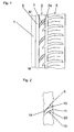
- Fig. 1 shows a profile for a tread of a pneumatic vehicle tire for passenger cars.
- the tread has a tread band 1 running along the equatorial line MM, which can be structured, for example, by blind grooves (not shown) and has two rows of blocks 2, 5 in the illustrated tread half, which are separated from one another and from the central tread band 1 by a respective circumferential and straight one Circumferential groove 3, 4 are separated.
- the second tread half not shown, can be analogous but deviating be executed.
- the shoulder block row 5 is divided by a plurality of transverse grooves 6 into blocks 5a.
- the block row 2 is divided by transverse grooves 7 into blocks 2a, wherein in the illustrated embodiment, the blocks 2a have a greater circumferential extent than the shoulder blocks 5a, since two shoulder blocks 5a corresponds to a block 2a.
- An additional structuring or structuring of the blocks 2a is effected by blind grooves 8, which run from the circumferential groove 4 into the blocks 2a.
- transverse grooves are to be understood as meaning any grooves which separate circumferentially successive, repeating profile structures from one another. Therefore, transverse grooves can also be diagonal, i. run at a relatively small angle to the circumferential direction of the tire.
- the transverse grooves 7 dividing the block row 2 into blocks 2a are bent at one point, so that they are composed of two sections 7a, 7b, the section 7a extending diagonally and the second extending more in the transverse direction.
- the kinked course of the transverse grooves 7 can be followed by the course of their groove bottom 11.
- the angle between the two sections 7a, 7b is an obtuse angle of the order of 120 to 175 °.
- the transverse grooves 7 in the block row 2 are therefore limited in each case by a block edge 9 with a recessed kink 16 and a block edge 10 with a projecting kink 17.
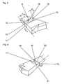
- the block flank 9 consists of four flank surfaces 12, 13, 14, 15.
- the two flank surfaces 12, 13 close to the groove base 11 and extend with respect to the radial direction preferably below the usual groove flanks angle in the order of magnitude between 0 and 5 °.
- the kink 16 is a line extending in the radial direction.
- the flank surface 13 is a quadrilateral, in particular a rectangle or a trap, with the kink 16 as a base.
- flank surface 12 closes towards the block surface a triangular flank surface 14, which is a to the radial direction at an acute angle ⁇ in the order of 20 ° and 70 ° extending inclined surface, which is an elongated triangle on the kink 16 extends beyond, so that the upper boundary edge of the flank surface 12, which is also the boundary edge of the flank surface 14 at the same time extends to the block surface and the kink 16 surmounted.
- the block flank 9 is completed by the fourth flank surface 15, which is a quadrilateral, which is also an oblique surface which extends at an angle ⁇ to the radial, which is smaller than ⁇ .
- flank surface 15 is positioned in the manner shown on the block edge 9 by one of its boundary edges of the block inside corner of the triangular flank surface 14 extends to the upper end of the kink 16.
- the mutual arrangement of the flank surfaces 12, 13, 14, 15 results in a particularly advantageous entanglement and mutual support of the flank surfaces 12 to 15, whereby the rigidity of the tread block in the tire circumferential direction is particularly favorably influenced.
- Fig. 4 shows a preferred embodiment of the block edge 10 with a projecting kink 17.
- the block edge 10 wiest three flank surfaces 18, 19, 20, wherein the two flank surfaces 18, 19 connect to the groove base 11 and preferably in the usual manner at an angle of 0 ° to 5 ° to the radial direction.
- the block Above the kink 17, the block is chamfered by the third, triangular flank surface 20.
- the triangular oblique flank surface 20 is inclined at an angle ⁇ of the order of 30 to 85 ° to the radial direction.
- the triangular shape of the surface 20 results from the projecting kink 17.
- the flank surface 20 may extend to the circumferential grooves or, as shown, end within the groove portions 7a, 7b. It is also possible to bevel the block 2a in a larger area, so that the resulting inclined surface becomes a pentagon.
- the invention is not limited to the illustrated embodiments. Thus, for example, it is possible to carry out only the recessed or merely the projecting block flank according to the invention.
Landscapes
- Engineering & Computer Science (AREA)
- Mechanical Engineering (AREA)
- Tires In General (AREA)
- Pulleys (AREA)
- Turning (AREA)
Description
- Die Erfindung betrifft einen Fahrzeugluftreifen mit einem Laufstreifen mit einem Profil, welches durch Umfangsnuten, Quernuten und dergleichen gebildete Profilpositive, wie Profilblöcke oder in Umfangsrichtung umlaufende Laufstreifenbänder aufweist, wobei Quernuten vorgesehen sind, die mit einer Knickstelle versehen sind, an welcher eine Richtungsänderung unter einem stumpfen Winkel erfolgt. Ein derartiger Reifen ist aus der US-A- 2002/0124922 bekannt.
- Fahrzeugluftreifen mit Laufstreifenprofilen mit Band- und / oder mit Blockstrukturen sind in unterschiedlichsten Ausführungsvarianten bekannt. Aus der EP-A-0 425 567 ist beispielsweise ein Reifen mit einem laufrichtungsgebunden ausgeführten Laufstreifenprofil bekannt, welches sich aus einer Anzahl von in Umfangsrichtung umlaufenden Blockreihen zusammensetzt.
- Es ist ferner bekannt, dass vor allem die Bremseigenschaften eines Reifens auf trockenem Untergrund durch die Steifigkeit des Laufstreifens in Längsrichtung beeinflussbar sind. Um die Bremseigenschaften auf trockenem Untergrund zu verbessern, ist es daher von Vorteil, Laufstreifenbänder vorzusehen oder die Blöcke in Blockreihen in Umfangsrichtung möglichst lang auszuführen. Auch die Ausführung der Quernuten spielt eine gewisse Rolle, so ist es zur Umfangsversteifung von Blöcken von Vorteil, die Quernuten nicht gerade verlaufen zu lassen, sondern mit einer Knickstelle in ihrem Verlauf zu versehen.
- Der Erfindung liegt die Aufgabe zu Grund, mit Quernuten versehene Laufstreifenprofile in Umfangsrichtung gezielt versteifen zu können.
- Gelöst wird die gestellte Aufgabe erfindungsgemäß durch Quernuten, die von zumindest einer Flanke begrenzt sind, welche aus zumindest drei Flankenflächen besteht, von welchen zumindest eine eine an die Blockoberseite anschließende Schrägfläche ist, die radial oberhalb der Knickstelle der Quernut ausgebildet ist.
- Auf diese Weise lassen sich die die Quernuten begrenzenden Blockflanken besonders vorteilhaft versteifen, insbesondere durch die Möglichkeit des gegenseitigen Abstützens der Flankenflächen, sodass die "Statik" des Profilblockes in Reifenumfangsrichtung in der erwünschten Weise beeinflussbar ist.
- Gemäß einer vorteilhaften Ausführungsform der Erfindung weist die mit einer rückspringenden Knickstelle versehene Blockflanke vier Flankenflächen auf, von welchen zwei an die Blockoberseite anschließende Schrägflächen sind und zwei an den Nutgrund anschließende, zumindest im Wesentlichen in radialer Richtung verlaufende und durch die Knickstelle voneinander getrennte Flächen sind. Zwei Schrägflächen lassen sich an einer Blockflanke mit einer rückspringenden Knickstelle vorteilhaft anordnen.
- Eine besonders günstige gegenseitige Abstützung und "Verschränkung" der beteiligten Blockflankenflächen ergibt sich dann, wenn die Schrägflächen unter unterschiedlichen Winkeln zur radialen Richtung verlaufen und wenn eine der beiden Schrägflächen eine längliche Dreieckform aufweist, wobei der den kleinsten Winkel aufweisende Eckbereich über die Knickstelle hinausragt.
- Eine besonders günstige gegenseitige Abstützung wird dadurch begünstigt, dass die andere Schrägfläche vorzugsweise eine Viereckform aufweist und eine Begrenzungskante besitzt, welche von der blockinnenseitig gelegenen Ecke der dreieckförmigen Schrägfläche zum oberen Ende der Knickstelle verläuft.
- G+t eine optimale Stabilisierung und Versteifung des Blockes in Umfangsrichtung spielt die Größe des Winkels der beiden Schrägflächen zur radialen Richtung eine gewisse Rolle. Besonders günstig ist es, wenn der Winkel, den die dreieckförmige Schrägfläche mit der radialen Richtung einschließt, 20° bis 70° beträgt und größer ist als der Winkel, den die andere Fläche mit der radialen Richtung einschließt.
- Die Blockflanke mit der vorspringenden Knickstelle lässt sich auf besonders einfache Weise derart gestalten, dass der Block in Umfangsrichtung versteift bzw. stabilisiert wird. Dazu ist vorgesehen, dass diese Blockflanke drei Flankenflächen aufweist, von welchen zwei zumindest im Wesentlichen in radialer Richtung verlaufen, an den Nutgrund anschließen und durch die Knickstelle voneinander getrennt sind, wobei die Schrägfläche radial außerhalb der Knickstelle, etwa mittig zu dieser, verläuft.
- Ein sehr guter Stabilisierungseffekt lässt sich dabei bereits mit einer dreieckförmig gestalteten Schrägfläche erzielen, die vergleichsweise kleinflächig ausgeführt sein kann. Dabei ist es von Vorteil, wenn der Winkel, den diese Schrägfläche mit der radialen Richtung einschließt, zwischen 30° und 85° gewählt wird.
- Weitere Merkmale, Vorteile und Einzelheiten der Erfindung werden nun anhand der Zeichnung, die ein Ausführungsbeispiel darstellt, näher beschrieben. Dabei zeigen
- Fig. 1 eine Teilabwicklung der einen Hälfte eines Profils eines Laufstreifens für einen Fahrzeugluftreifen,
- Fig. 2 eine Draufsicht auf eine Quernut in größerem Maßstab,
- Fig. 3 eine Schrägansicht von zwei aufeinanderfolgenden Blöcken und
- Fig. 4 eine Schrägansicht der beiden Blöcke aus Fig. 3 von der anderen Richtung her gesehen.
- Fig. 1 zeigt ein Profil für einen Laufstreifen eines Fahrzeugluftreifens für Personenkraftwagen. Das Profil weist ein entlang der Äquatorlinie M-M verlaufendes Laufstreifenband 1 auf, welches beispielsweise durch nicht gezeigte Sacknuten strukturiert sein kann und in der dargestellten Laufstreifenhälfte zwei Blockreihen 2, 5 aufweist, welche voneinander und vom mittigen Laufstreifenband 1 durch je eine breite in Umfangsrichtung und gerade umlaufende Umfangsnut 3, 4 getrennt sind. Die zweite nicht gezeigte Laufstreifenhälfte kann analog aber abweichend ausgeführt sein. Die Schulterblockreihe 5 ist durch eine Vielzahl von Quernuten 6 in Blöcke 5a gegliedert. Auch die Blockreihe 2 ist durch Quernuten 7 in Blöcke 2a gegliedert, wobei bei der dargestellten Ausführungsform die Blöcke 2a eine größere Umfangserstreckung aufweisen als die Schulterblöcke 5a, da zwei Schulterblöcken 5a ein Block 2a entspricht. Eine zusätzliche Gliederung bzw. Strukturierung der Blöcke 2a erfolgt durch Sacknuten 8, die von der Umfangsnut 4 in die Blöcke 2a hineinverlaufen.
- Unter Quernuten im Sinne der Erfindung sind jegliche Nuten zu verstehen, die in Umfangsrichtung aufeinanderfolgende, sich wiederholende Profilstrukturen voneinander trennen. Quernuten können daher auch diagonal, d.h. unter einem vergleichsweise kleinen Winkel zur Umfangsrichtung des Reifens verlaufen.
- Bei dem in Fig. 1 gezeigten Ausführungsbeispiel sind die die Blockreihe 2 in Blöcke 2a gliedernden Quernuten 7 an einer Stelle geknickt, sodass sie sich aus zwei Abschnitten 7a, 7b zusammensetzen, wobei sich der Abschnitt 7a diagonal erstreckt und der zweite mehr in Querrichtung verläuft. Der geknickte Verlauf der Quernuten 7 lässt sich anhand des Verlaufes ihres Nutgrundes 11 verfolgen. Der Winkel zwischen den beiden Abschnitten 7a, 7b ist ein stumpfer Winkel in der Größenordnung von 120 bis 175°. Die Quernuten 7 in der Blockreihe 2 werden daher jeweils durch eine Blockflanke 9 mit einer rückspringenden Knickstelle 16 und eine Blockflanke 10 mit einer vorspringenden Knickstelle 17 begrenzt.
- Anhand der Fig. 2, 3 und 4 wird nun nachfolgend die besondere Ausführung der Blockflanken 9, 10 näher beschrieben. Wie insbesondere Fig. 2 zeigt, besteht die Blockflanke 9 aus vier Flankenflächen 12, 13, 14, 15. Die beide Flankenflächen 12, 13 schließen an den Nutgrund 11 an und verlaufen gegenüber der radialen Richtung vorzugsweise unter dem für Nutflanken üblichen Winkel in der Größenordnung zwischen 0 und 5°. Die Knickstelle 16 ist eine in radialer Richtung verlaufende Linie. Die Flankenfläche 13 ist ein Viereck, insbesondere ein Rechteck oder ein Trapze, mit der Knickstelle 16 als Basis. An die Flankenfläche 12 schließt Richtung Blockoberfläche eine dreieckförmige Flankenfläche 14 an, welche eine zur radialen Richtung unter einem spitzen Winkel α in der Größenordnung von 20° und 70° verlaufende Schrägfläche ist, die sich als längliches Dreieck über die Knickstelle 16 hinaus erstreckt, sodass die obere Begrenzungskante der Flankenfläche 12, die gleichzeitig auch die Begrenzungskante der Flankenfläche 14 ist, bis an die Blockoberfläche reicht und die Knickstelle 16 überragt. Die Blockflanke 9 wird durch die vierte Flankenfläche 15 komplettiert, die ein Viereck ist, welches ebenfalls eine Schrägfläche ist, die unter einem Winkel β zur Radialen verläuft, welcher kleiner als α ist. Dadurch wird die Flankenfläche 15 in der gezeigten Weise an der Blockflanke 9 positioniert, indem eine ihrer Begrenzungskanten von der blockinnenseitig gelegenen Ecke der dreieckförmigen Flankenfläche 14 zum oberen Ende der Knickstelle 16 verläuft. Durch die gegenseitige Anordnung der Flankenflächen 12, 13, 14, 15 ergibt sich eine besonders vorteilhafte Verschränkung und gegenseitige Abstützung der Flankenflächen 12 bis 15, wodurch die Steifigkeit des Profilblockes in Reifenumfangsrichtung besonders günstig beeinflusst wird.
- Fig. 4 zeigt eine bevorzugte Ausführung der Blockflanke 10 mit einer vorspringenden Knickstelle 17. Die Blockflanke 10 wiest drei Flankenflächen 18, 19, 20 auf, wobei die beiden Flankenflächen 18, 19 an den Nutgrund 11 anschließen und vorzugsweise in üblicher Weise unter einem Winkel von 0° bis 5° zur radialen Richtung verlaufen. Oberhalb der Knickstelle 17 ist der Block durch die dritte, dreieckförmige Flankenfläche 20 abgeschrägt. Die dreieckförmige schräge Flankenfläche 20 ist unter einem Winkel γ in der Größenordnung von 30 bis 85° gegenüber der radialen Richtung geneigt. Die Dreieckform der Fläche 20 ergibt sich durch die vorspringende Knickstelle 17. Die Flankenfläche 20 kann sich bis zu den Umfangsnuten erstrecken oder, wie dargestellt, innerhalb der Nutabschnitte 7a, 7b enden. Es ist ferner möglich, den Block 2a größflächiger abzuschrägen, sodass die sich ergebende Schrägfläche ein Fünfeck wird.
- Die Erfindung ist auf die dargestellten Ausführungsformen nicht eingeschränkt. So ist es beispielsweise möglich, lediglich die rückspringende oder lediglich die vorspringende Blockflanke gemäß der Erfindung auszuführen.
Claims (9)
- Fahrzeugluftreifen mit einem Laufstreifen mit einem Profil, welches durch Umfangsnuten (3, 4), Quernuten (6, 7) und dergleichen gebildete Profilpositive, wie Profilblöcke (2a, 5a) oder in Umfangsrichtung umlaufende Laufstreifenbänder (1) aufweist, wobei Quernuten (7) vorgesehen sind, die mit einer Knickstelle (16, 17) versehen sind, an welcher eine Richtungsänderung unter einem stumpfen Winkel erfolgt,
gekennzeichnet durch
geknickte Quernuten (7), deren zumindest eine sie begrenzende Blockflanke aus zumindest drei Flankenflächen (12 bis 15, 18 bis 20) besteht, von welchen zumindest eine eine an die Blockoberseite anschließende Schrägfläche (14, 20) ist, die radial oberhalb der Knickstelle (16, 17) ausgebildet ist. - Fahrzeugluftreifen nach Anspruch 1, dadurch gekennzeichnet, dass die mit einer rückspringenden Knickstelle (16) versehene Blockflanke (9) vier Flankenflächen (12 bis 15) aufweist, von welchen zwei an die Blockoberseite anschließende Schrägflächen (14, 15) sind und zwei an den Nutgrund (11) anschließen, zumindest im Wesentlichen in radialer Richtung verlaufen und durch die Knickstelle (16) voneinander getrennt sind.
- Fahrzeugluftreifen nach Anspruch 2, dadurch gekennzeichnet, dass die beiden Schrägflächen (14, 15) unter unterschiedlichen Winkeln (α, β) zur radialen Richtung verlaufen.
- Fahrzeugluftreifen nach einem der Ansprüche 1 bis 3, dadurch gekennzeichnet, dass die eine der beiden Schrägflächen (14) eine längliche Dreieckform aufweist, wobei der den kleinsten Winkel aufweisende Eckbereich über die Knickstelle (16) hinausragt.
- Fahrzeugluftreifen nach einem der Ansprüche 1 bis 4, dadurch gekennzeichnet, dass die andere Schrägfläche (15) vorzugsweise eine Viereckform aufweist und eine Begrenzungskante besitzt, welche von der blockinnenseitig gelegenen Ecke der anderen Schrägfläche (14) zum oberen Ende der Knickstelle (16) verläuft.
- Fahrzeugluftreifen nach einem der Ansprüche 1 bis 5, dadurch gekennzeichnet, dass der Winkel (α), den die dreieckförmige Schrägfläche (14) mit der radialen Richtung einschließt, 20° bis 70° beträgt und größer ist, als der Winkel (β), den die andere Schrägfläche (15) mit der radialen Richtung einschließt.
- Fahrzeugluftreifen nach Anspruch 1, dadurch gekennzeichnet, dass die mit einer vorspringenden Knickstelle (17) versehene Blockflanke (10) drei Flankenflächen (18 bis 20) aufweist, von welchen zwei zumindest im Wesentlichen in radialer Richtung verlaufen, an den Nutgrund (11) anschließen und durch die Knickstelle (17) voneinander getrennt sind, wobei die Schrägfläche (20) radial außerhalb der Knickstelle (17) etwa mittig zu dieser verläuft.
- Fahrzeugluftreifen nach Anspruch 1 oder 7, dadurch gekennzeichnet, dass die an der mit einer vorspringenden Knickstelle (17) versehenen Blockflanke (10) vorgesehene Schrägfläche (20) dreieckförmig ist.
- Fahrzeugluftreifen nach Anspruch 7 oder 8, dadurch gekennzeichnet, dass der Winkel (γ), den die Schrägfläche (20) mit der radialen Richtung einschließt, 30° bis 85° beträgt.
Priority Applications (5)
| Application Number | Priority Date | Filing Date | Title |
|---|---|---|---|
| AT04007320T ATE363402T1 (de) | 2004-03-26 | 2004-03-26 | Fahrzeugluftreifen |
| ES04007320T ES2287600T3 (es) | 2004-03-26 | 2004-03-26 | Neumatico de vehiculo. |
| DE502004003944T DE502004003944D1 (de) | 2004-03-26 | 2004-03-26 | Fahrzeugluftreifen |
| EP04007320A EP1580035B1 (de) | 2004-03-26 | 2004-03-26 | Fahrzeugluftreifen |
| US11/088,751 US7503361B2 (en) | 2004-03-26 | 2005-03-25 | Tire with tread having transverse grooves forming block flank surfaces |
Applications Claiming Priority (1)
| Application Number | Priority Date | Filing Date | Title |
|---|---|---|---|
| EP04007320A EP1580035B1 (de) | 2004-03-26 | 2004-03-26 | Fahrzeugluftreifen |
Publications (2)
| Publication Number | Publication Date |
|---|---|
| EP1580035A1 EP1580035A1 (de) | 2005-09-28 |
| EP1580035B1 true EP1580035B1 (de) | 2007-05-30 |
Family
ID=34854631
Family Applications (1)
| Application Number | Title | Priority Date | Filing Date |
|---|---|---|---|
| EP04007320A Expired - Lifetime EP1580035B1 (de) | 2004-03-26 | 2004-03-26 | Fahrzeugluftreifen |
Country Status (5)
| Country | Link |
|---|---|
| US (1) | US7503361B2 (de) |
| EP (1) | EP1580035B1 (de) |
| AT (1) | ATE363402T1 (de) |
| DE (1) | DE502004003944D1 (de) |
| ES (1) | ES2287600T3 (de) |
Families Citing this family (12)
| Publication number | Priority date | Publication date | Assignee | Title |
|---|---|---|---|---|
| US7874331B2 (en) * | 2007-03-02 | 2011-01-25 | The Goodyear Tire & Rubber Company | Pneumatic tire with tread having chamfer located in notch |
| DE102010060616A1 (de) * | 2010-11-17 | 2012-05-24 | Continental Reifen Deutschland Gmbh | Laufstreifenprofil eines Fahrzeugluftreifens |
| US9278582B2 (en) | 2010-12-21 | 2016-03-08 | Bridgestone Americas Tire Operations, Llc | Tire tread having developing grooves |
| JP5876227B2 (ja) * | 2011-04-08 | 2016-03-02 | 株式会社ブリヂストン | タイヤ |
| USD741792S1 (en) * | 2012-06-19 | 2015-10-27 | Bridgestone Corporation | Tread portion of an automobile tire |
| US10926586B2 (en) | 2013-12-26 | 2021-02-23 | Bridgestone Americas Tire Operations, Llc | Tire tread having a flexible gate apparatus |
| DE102014220981A1 (de) * | 2014-10-16 | 2016-04-21 | Continental Reifen Deutschland Gmbh | Fahrzeugluftreifen |
| JP6720551B2 (ja) * | 2016-01-21 | 2020-07-08 | 横浜ゴム株式会社 | 空気入りタイヤ |
| JP6963485B2 (ja) * | 2017-12-13 | 2021-11-10 | Toyo Tire株式会社 | 空気入りタイヤ |
| JP7497607B2 (ja) * | 2020-04-30 | 2024-06-11 | 住友ゴム工業株式会社 | タイヤ |
| CN115635802A (zh) * | 2021-07-19 | 2023-01-24 | 住友橡胶工业株式会社 | 轮胎 |
| JP7669844B2 (ja) | 2021-07-19 | 2025-04-30 | 住友ゴム工業株式会社 | タイヤ |
Family Cites Families (11)
| Publication number | Priority date | Publication date | Assignee | Title |
|---|---|---|---|---|
| FR2312385A1 (fr) * | 1975-05-30 | 1976-12-24 | Uniroyal | Structure de bande de roulement et enveloppe de bandage pneumatique en comportant application |
| JPS52140102A (en) * | 1976-05-19 | 1977-11-22 | Bridgestone Corp | Pneumatic tyre with less partial wear |
| JPS62255203A (ja) * | 1986-04-30 | 1987-11-07 | Bridgestone Corp | 空気入りラジアルタイヤ |
| JPH01178006A (ja) * | 1987-12-30 | 1989-07-14 | Toyo Tire & Rubber Co Ltd | W形の副溝をもつ高速走行可能に空気入りタイヤ |
| JP2650040B2 (ja) * | 1988-04-28 | 1997-09-03 | 横浜ゴム株式会社 | 乗用車用空気入りタイヤ |
| DE3824466A1 (de) | 1988-07-19 | 1990-01-25 | Putzmeister Maschf | Mehrzylinder-dickstoffpumpe |
| US5127455A (en) * | 1990-09-28 | 1992-07-07 | Michelin Recherche Et Technique | Drive axle truck tire |
| EP0602989A1 (de) * | 1992-12-16 | 1994-06-22 | Sumitomo Rubber Industries, Co. Ltd | Luftreifen |
| DE69731888T2 (de) * | 1996-12-27 | 2005-05-19 | Bridgestone Corp. | Verfahren zum entwerfen von luftreifen |
| JP3938618B2 (ja) * | 1997-08-25 | 2007-06-27 | 東洋ゴム工業株式会社 | 空気入りタイヤ |
| KR100839139B1 (ko) * | 1998-10-30 | 2008-06-19 | 피렐리 타이어 소시에떼 퍼 아찌오니 | 특히 화물차 및 화물차와 유사한 차량용 원동 차량 타이어 |
-
2004
- 2004-03-26 DE DE502004003944T patent/DE502004003944D1/de not_active Expired - Lifetime
- 2004-03-26 AT AT04007320T patent/ATE363402T1/de not_active IP Right Cessation
- 2004-03-26 ES ES04007320T patent/ES2287600T3/es not_active Expired - Lifetime
- 2004-03-26 EP EP04007320A patent/EP1580035B1/de not_active Expired - Lifetime
-
2005
- 2005-03-25 US US11/088,751 patent/US7503361B2/en not_active Expired - Fee Related
Also Published As
| Publication number | Publication date |
|---|---|
| US20050217775A1 (en) | 2005-10-06 |
| EP1580035A1 (de) | 2005-09-28 |
| DE502004003944D1 (de) | 2007-07-12 |
| ATE363402T1 (de) | 2007-06-15 |
| ES2287600T3 (es) | 2007-12-16 |
| US7503361B2 (en) | 2009-03-17 |
Similar Documents
| Publication | Publication Date | Title |
|---|---|---|
| EP2349746B1 (de) | Fahrzeugluftreifen | |
| EP2785536B1 (de) | Fahrzeugluftreifen | |
| EP2892736B1 (de) | Fahrzeugluftreifen | |
| EP2965925B1 (de) | Fahrzeugluftreifen | |
| EP2646264B1 (de) | Fahrzeugluftreifen | |
| EP2892735B1 (de) | Fahrzeugluftreifen | |
| DE102012109712A1 (de) | Fahrzeugluftreifen | |
| EP1580035B1 (de) | Fahrzeugluftreifen | |
| DE7312392U (de) | Luftreifen | |
| DE60017184T2 (de) | Reifenlaufflächenprofil für fahrzeuge mit hoher belastungsfähigkeit | |
| EP1588869B1 (de) | Fahrzeugluftreifen | |
| EP0189199B1 (de) | Fahrzeugluftreifen | |
| EP2785537B1 (de) | Fahrzeugluftreifen | |
| DE19957914C2 (de) | Fahrzeugluftreifen | |
| WO2016128084A1 (de) | Fahrzeugluftreifen | |
| DE102008037498A1 (de) | Fahrzeugluftreifen | |
| EP2855172B1 (de) | Fahrzeugluftreifen | |
| EP2219885B1 (de) | Fahrzeugluftreifen | |
| WO2015086182A1 (de) | Fahrzeugluftreifen | |
| EP1080949A2 (de) | Fahrzeugluftreifen | |
| EP4504530B1 (de) | Fahrzeugreifen | |
| EP4313632B1 (de) | Fahrzeugluftreifen | |
| EP3551474B1 (de) | Fahrzeugluftreifen | |
| DE102024108084A1 (de) | Fahrzeugreifen | |
| DE102022210140A1 (de) | Fahrzeugreifen |
Legal Events
| Date | Code | Title | Description |
|---|---|---|---|
| PUAI | Public reference made under article 153(3) epc to a published international application that has entered the european phase |
Free format text: ORIGINAL CODE: 0009012 |
|
| AK | Designated contracting states |
Kind code of ref document: A1 Designated state(s): AT BE BG CH CY CZ DE DK EE ES FI FR GB GR HU IE IT LI LU MC NL PL PT RO SE SI SK TR |
|
| AX | Request for extension of the european patent |
Extension state: AL LT LV MK |
|
| 17P | Request for examination filed |
Effective date: 20060328 |
|
| AKX | Designation fees paid |
Designated state(s): AT BE BG CH CY CZ DE DK EE ES FI FR GB GR HU IE IT LI LU MC NL PL PT RO SE SI SK TR |
|
| GRAP | Despatch of communication of intention to grant a patent |
Free format text: ORIGINAL CODE: EPIDOSNIGR1 |
|
| GRAS | Grant fee paid |
Free format text: ORIGINAL CODE: EPIDOSNIGR3 |
|
| GRAA | (expected) grant |
Free format text: ORIGINAL CODE: 0009210 |
|
| AK | Designated contracting states |
Kind code of ref document: B1 Designated state(s): AT BE BG CH CY CZ DE DK EE ES FI FR GB GR HU IE IT LI LU MC NL PL PT RO SE SI SK TR |
|
| PG25 | Lapsed in a contracting state [announced via postgrant information from national office to epo] |
Ref country code: FI Free format text: LAPSE BECAUSE OF FAILURE TO SUBMIT A TRANSLATION OF THE DESCRIPTION OR TO PAY THE FEE WITHIN THE PRESCRIBED TIME-LIMIT Effective date: 20070530 |
|
| REG | Reference to a national code |
Ref country code: GB Ref legal event code: FG4D Free format text: NOT ENGLISH |
|
| REG | Reference to a national code |
Ref country code: CH Ref legal event code: EP |
|
| REG | Reference to a national code |
Ref country code: IE Ref legal event code: FG4D Free format text: LANGUAGE OF EP DOCUMENT: GERMAN |
|
| REF | Corresponds to: |
Ref document number: 502004003944 Country of ref document: DE Date of ref document: 20070712 Kind code of ref document: P |
|
| PG25 | Lapsed in a contracting state [announced via postgrant information from national office to epo] |
Ref country code: SE Free format text: LAPSE BECAUSE OF FAILURE TO SUBMIT A TRANSLATION OF THE DESCRIPTION OR TO PAY THE FEE WITHIN THE PRESCRIBED TIME-LIMIT Effective date: 20070830 |
|
| GBT | Gb: translation of ep patent filed (gb section 77(6)(a)/1977) |
Effective date: 20070815 |
|
| ET | Fr: translation filed | ||
| PG25 | Lapsed in a contracting state [announced via postgrant information from national office to epo] |
Ref country code: PL Free format text: LAPSE BECAUSE OF FAILURE TO SUBMIT A TRANSLATION OF THE DESCRIPTION OR TO PAY THE FEE WITHIN THE PRESCRIBED TIME-LIMIT Effective date: 20070530 |
|
| NLV1 | Nl: lapsed or annulled due to failure to fulfill the requirements of art. 29p and 29m of the patents act | ||
| REG | Reference to a national code |
Ref country code: ES Ref legal event code: FG2A Ref document number: 2287600 Country of ref document: ES Kind code of ref document: T3 |
|
| REG | Reference to a national code |
Ref country code: IE Ref legal event code: FD4D |
|
| PG25 | Lapsed in a contracting state [announced via postgrant information from national office to epo] |
Ref country code: SI Free format text: LAPSE BECAUSE OF FAILURE TO SUBMIT A TRANSLATION OF THE DESCRIPTION OR TO PAY THE FEE WITHIN THE PRESCRIBED TIME-LIMIT Effective date: 20070530 Ref country code: CZ Free format text: LAPSE BECAUSE OF FAILURE TO SUBMIT A TRANSLATION OF THE DESCRIPTION OR TO PAY THE FEE WITHIN THE PRESCRIBED TIME-LIMIT Effective date: 20070530 Ref country code: BG Free format text: LAPSE BECAUSE OF FAILURE TO SUBMIT A TRANSLATION OF THE DESCRIPTION OR TO PAY THE FEE WITHIN THE PRESCRIBED TIME-LIMIT Effective date: 20070830 Ref country code: NL Free format text: LAPSE BECAUSE OF FAILURE TO SUBMIT A TRANSLATION OF THE DESCRIPTION OR TO PAY THE FEE WITHIN THE PRESCRIBED TIME-LIMIT Effective date: 20070530 Ref country code: IE Free format text: LAPSE BECAUSE OF FAILURE TO SUBMIT A TRANSLATION OF THE DESCRIPTION OR TO PAY THE FEE WITHIN THE PRESCRIBED TIME-LIMIT Effective date: 20070530 Ref country code: PT Free format text: LAPSE BECAUSE OF FAILURE TO SUBMIT A TRANSLATION OF THE DESCRIPTION OR TO PAY THE FEE WITHIN THE PRESCRIBED TIME-LIMIT Effective date: 20071030 Ref country code: DK Free format text: LAPSE BECAUSE OF FAILURE TO SUBMIT A TRANSLATION OF THE DESCRIPTION OR TO PAY THE FEE WITHIN THE PRESCRIBED TIME-LIMIT Effective date: 20070530 |
|
| PG25 | Lapsed in a contracting state [announced via postgrant information from national office to epo] |
Ref country code: SK Free format text: LAPSE BECAUSE OF FAILURE TO SUBMIT A TRANSLATION OF THE DESCRIPTION OR TO PAY THE FEE WITHIN THE PRESCRIBED TIME-LIMIT Effective date: 20070530 |
|
| PLBE | No opposition filed within time limit |
Free format text: ORIGINAL CODE: 0009261 |
|
| STAA | Information on the status of an ep patent application or granted ep patent |
Free format text: STATUS: NO OPPOSITION FILED WITHIN TIME LIMIT |
|
| PG25 | Lapsed in a contracting state [announced via postgrant information from national office to epo] |
Ref country code: GR Free format text: LAPSE BECAUSE OF FAILURE TO SUBMIT A TRANSLATION OF THE DESCRIPTION OR TO PAY THE FEE WITHIN THE PRESCRIBED TIME-LIMIT Effective date: 20070831 |
|
| 26N | No opposition filed |
Effective date: 20080303 |
|
| PG25 | Lapsed in a contracting state [announced via postgrant information from national office to epo] |
Ref country code: RO Free format text: LAPSE BECAUSE OF FAILURE TO SUBMIT A TRANSLATION OF THE DESCRIPTION OR TO PAY THE FEE WITHIN THE PRESCRIBED TIME-LIMIT Effective date: 20070530 |
|
| BERE | Be: lapsed |
Owner name: CONTINENTAL A.G. Effective date: 20080331 |
|
| PG25 | Lapsed in a contracting state [announced via postgrant information from national office to epo] |
Ref country code: MC Free format text: LAPSE BECAUSE OF NON-PAYMENT OF DUE FEES Effective date: 20080331 |
|
| REG | Reference to a national code |
Ref country code: CH Ref legal event code: PL |
|
| GBPC | Gb: european patent ceased through non-payment of renewal fee |
Effective date: 20080326 |
|
| PG25 | Lapsed in a contracting state [announced via postgrant information from national office to epo] |
Ref country code: LI Free format text: LAPSE BECAUSE OF NON-PAYMENT OF DUE FEES Effective date: 20080331 Ref country code: CH Free format text: LAPSE BECAUSE OF NON-PAYMENT OF DUE FEES Effective date: 20080331 Ref country code: EE Free format text: LAPSE BECAUSE OF FAILURE TO SUBMIT A TRANSLATION OF THE DESCRIPTION OR TO PAY THE FEE WITHIN THE PRESCRIBED TIME-LIMIT Effective date: 20070530 |
|
| PG25 | Lapsed in a contracting state [announced via postgrant information from national office to epo] |
Ref country code: BE Free format text: LAPSE BECAUSE OF NON-PAYMENT OF DUE FEES Effective date: 20080331 |
|
| REG | Reference to a national code |
Ref country code: ES Ref legal event code: FD2A Effective date: 20080327 |
|
| PG25 | Lapsed in a contracting state [announced via postgrant information from national office to epo] |
Ref country code: GB Free format text: LAPSE BECAUSE OF NON-PAYMENT OF DUE FEES Effective date: 20080326 |
|
| PG25 | Lapsed in a contracting state [announced via postgrant information from national office to epo] |
Ref country code: CY Free format text: LAPSE BECAUSE OF FAILURE TO SUBMIT A TRANSLATION OF THE DESCRIPTION OR TO PAY THE FEE WITHIN THE PRESCRIBED TIME-LIMIT Effective date: 20070530 Ref country code: ES Free format text: LAPSE BECAUSE OF NON-PAYMENT OF DUE FEES Effective date: 20080327 |
|
| PG25 | Lapsed in a contracting state [announced via postgrant information from national office to epo] |
Ref country code: AT Free format text: LAPSE BECAUSE OF NON-PAYMENT OF DUE FEES Effective date: 20080326 |
|
| PG25 | Lapsed in a contracting state [announced via postgrant information from national office to epo] |
Ref country code: HU Free format text: LAPSE BECAUSE OF FAILURE TO SUBMIT A TRANSLATION OF THE DESCRIPTION OR TO PAY THE FEE WITHIN THE PRESCRIBED TIME-LIMIT Effective date: 20071201 Ref country code: LU Free format text: LAPSE BECAUSE OF NON-PAYMENT OF DUE FEES Effective date: 20080326 |
|
| PG25 | Lapsed in a contracting state [announced via postgrant information from national office to epo] |
Ref country code: TR Free format text: LAPSE BECAUSE OF FAILURE TO SUBMIT A TRANSLATION OF THE DESCRIPTION OR TO PAY THE FEE WITHIN THE PRESCRIBED TIME-LIMIT Effective date: 20070530 |
|
| PGFP | Annual fee paid to national office [announced via postgrant information from national office to epo] |
Ref country code: IT Payment date: 20140327 Year of fee payment: 11 |
|
| PG25 | Lapsed in a contracting state [announced via postgrant information from national office to epo] |
Ref country code: IT Free format text: LAPSE BECAUSE OF NON-PAYMENT OF DUE FEES Effective date: 20150326 |
|
| REG | Reference to a national code |
Ref country code: FR Ref legal event code: PLFP Year of fee payment: 13 |
|
| REG | Reference to a national code |
Ref country code: FR Ref legal event code: PLFP Year of fee payment: 14 |
|
| REG | Reference to a national code |
Ref country code: FR Ref legal event code: PLFP Year of fee payment: 15 |
|
| PGFP | Annual fee paid to national office [announced via postgrant information from national office to epo] |
Ref country code: DE Payment date: 20220331 Year of fee payment: 19 |
|
| PGFP | Annual fee paid to national office [announced via postgrant information from national office to epo] |
Ref country code: FR Payment date: 20220322 Year of fee payment: 19 |
|
| REG | Reference to a national code |
Ref country code: DE Ref legal event code: R119 Ref document number: 502004003944 Country of ref document: DE |
|
| PG25 | Lapsed in a contracting state [announced via postgrant information from national office to epo] |
Ref country code: FR Free format text: LAPSE BECAUSE OF NON-PAYMENT OF DUE FEES Effective date: 20230331 Ref country code: DE Free format text: LAPSE BECAUSE OF NON-PAYMENT OF DUE FEES Effective date: 20231003 |