EP2842650B1 - Sheet metal forming process and system - Google Patents
Sheet metal forming process and system Download PDFInfo
- Publication number
- EP2842650B1 EP2842650B1 EP13731351.6A EP13731351A EP2842650B1 EP 2842650 B1 EP2842650 B1 EP 2842650B1 EP 13731351 A EP13731351 A EP 13731351A EP 2842650 B1 EP2842650 B1 EP 2842650B1
- Authority
- EP
- European Patent Office
- Prior art keywords
- simulated
- deep drawing
- simulation
- ironing
- thickness
- Prior art date
- Legal status (The legal status is an assumption and is not a legal conclusion. Google has not performed a legal analysis and makes no representation as to the accuracy of the status listed.)
- Active
Links
Images


Classifications
-
- B—PERFORMING OPERATIONS; TRANSPORTING
- B21—MECHANICAL METAL-WORKING WITHOUT ESSENTIALLY REMOVING MATERIAL; PUNCHING METAL
- B21K—MAKING FORGED OR PRESSED METAL PRODUCTS, e.g. HORSE-SHOES, RIVETS, BOLTS OR WHEELS
- B21K21/00—Making hollow articles not covered by a single preceding sub-group
- B21K21/04—Shaping thin-walled hollow articles, e.g. cartridges
-
- B—PERFORMING OPERATIONS; TRANSPORTING
- B21—MECHANICAL METAL-WORKING WITHOUT ESSENTIALLY REMOVING MATERIAL; PUNCHING METAL
- B21D—WORKING OR PROCESSING OF SHEET METAL OR METAL TUBES, RODS OR PROFILES WITHOUT ESSENTIALLY REMOVING MATERIAL; PUNCHING METAL
- B21D22/00—Shaping without cutting, by stamping, spinning, or deep-drawing
- B21D22/20—Deep-drawing
- B21D22/22—Deep-drawing with devices for holding the edge of the blanks
-
- B—PERFORMING OPERATIONS; TRANSPORTING
- B21—MECHANICAL METAL-WORKING WITHOUT ESSENTIALLY REMOVING MATERIAL; PUNCHING METAL
- B21D—WORKING OR PROCESSING OF SHEET METAL OR METAL TUBES, RODS OR PROFILES WITHOUT ESSENTIALLY REMOVING MATERIAL; PUNCHING METAL
- B21D22/00—Shaping without cutting, by stamping, spinning, or deep-drawing
- B21D22/20—Deep-drawing
- B21D22/28—Deep-drawing of cylindrical articles using consecutive dies
-
- B—PERFORMING OPERATIONS; TRANSPORTING
- B21—MECHANICAL METAL-WORKING WITHOUT ESSENTIALLY REMOVING MATERIAL; PUNCHING METAL
- B21D—WORKING OR PROCESSING OF SHEET METAL OR METAL TUBES, RODS OR PROFILES WITHOUT ESSENTIALLY REMOVING MATERIAL; PUNCHING METAL
- B21D51/00—Making hollow objects
- B21D51/16—Making hollow objects characterised by the use of the objects
- B21D51/54—Making hollow objects characterised by the use of the objects cartridge cases, e.g. for ammunition, for letter carriers in pneumatic-tube plants
-
- F—MECHANICAL ENGINEERING; LIGHTING; HEATING; WEAPONS; BLASTING
- F42—AMMUNITION; BLASTING
- F42B—EXPLOSIVE CHARGES, e.g. FOR BLASTING, FIREWORKS, AMMUNITION
- F42B33/00—Manufacture of ammunition; Dismantling of ammunition; Apparatus therefor
-
- F—MECHANICAL ENGINEERING; LIGHTING; HEATING; WEAPONS; BLASTING
- F42—AMMUNITION; BLASTING
- F42B—EXPLOSIVE CHARGES, e.g. FOR BLASTING, FIREWORKS, AMMUNITION
- F42B5/00—Cartridge ammunition, e.g. separately-loaded propellant charges
- F42B5/26—Cartridge cases
- F42B5/28—Cartridge cases of metal, i.e. the cartridge-case tube is of metal
-
- G—PHYSICS
- G06—COMPUTING OR CALCULATING; COUNTING
- G06F—ELECTRIC DIGITAL DATA PROCESSING
- G06F30/00—Computer-aided design [CAD]
- G06F30/20—Design optimisation, verification or simulation
-
- G—PHYSICS
- G06—COMPUTING OR CALCULATING; COUNTING
- G06F—ELECTRIC DIGITAL DATA PROCESSING
- G06F2113/00—Details relating to the application field
- G06F2113/24—Sheet material
Definitions
- the present invention relates to a forming method and system for obtaining an essentially cylindrical and essentially hollow final metal part, with a thickness of the bottom that is essentially greater than the thickness of its walls, from a preferably disc-shaped sheet metal.
- the invention is specifically comprised in the metal working sector, and more specifically in the manufacture of ammunition cartridge cases.
- Deep drawing is a technique that allows obtaining from planar and essentially thin sheet metal with a specific thickness an object the shape of which is predetermined and is essentially cylindrical and hollow.
- the sheet is deep drawn in a deep drawing die by the mechanical action of a punch.
- Multistage deep drawing is characterized by being a process comprising several consecutive deep drawing and redrawing operations.
- Deep drawing is the action of mechanically deforming planar sheet metal against the deep drawing die with the aid of the punch.
- Redrawing comprises repeated deep drawing stages in which the part is gradually deformed iteratively until reaching the desired final shape.
- Ironing is characterized by being a process which allows reducing the thickness of the wall of the previously deep drawn part and consists of passing the previously deep drawn part through an ironing die.
- the manufacture of ammunition cartridge cases is done by first performing the deep drawing operations to obtain the inner shape of the part and to subsequently reduce the thickness of the walls and increase the length of the part by means of successive ironing operations.
- the deep drawing, redrawing and ironing stages are fundamentally defined by means of design rules based on the empirical tests without taking into account the plastic evolution of the material and without considerations concerning the combination of stages or optimization of the process.
- the present invention provides a different process that allows manufacturing final parts with different design parameters and an optimized process that substantially improves the results obtained up until now.
- the present invention provides a process that is different from the process of the state of the art that allows manufacturing final parts with different design parameters, leading to a lower process cost and lower power consumption by basing the dependence of the latter on the manufacturing forces, work and time.
- the invention describes a sheet metal forming process for obtaining an essentially cylindrical and essentially hollow final metal part according to claim 1 and a sheet metal forming system according to claim 6.
- forming refers to the forming of metal materials, i.e., the technique of giving shape to a sheet metal or metal disc to obtain a part having the desired shape and volume. "Molding” or “forming” shall be referred to indistinctly hereinafter.
- a first inventive aspect relates to a sheet metal forming process for obtaining an essentially cylindrical and essentially hollow final metal part in a system comprising at least the followin g elements:
- the process is performed in a system comprising the described elements comprised in machinery used for the process, each one performing a function in the simultaneous deep drawing and ironing process of the invention.
- one deep drawing die is used for each deep drawing step such that it contains the shape that will be given to the metal part to be obtained in each step.
- the present invention represents each step with a sign i and n steps are completed.
- the punches are adapted to the inner dimensions of the inner diameters of the intermediate parts in the intermediate stages to be obtained in the combined process.
- Each punch in each stage i mechanically operates on the sheet or disc (first stage) or metal part (subsequent stages), first passing the part through the deep drawing die and then through the ironing die, and so on and so forth for each stage.
- the blank-holder elements for holding or securing the part that is being deep drawn (securing means for securing the part) of each stage i are used to prevent the occurrence of creases or wrinkles during the combined, simultaneous deep drawing/ironing operation.
- processing means are used to program machinery operation with parameters such as the working pressure of the machine and the travelling speeds of the punches during the approach, operation and recovery.
- each of the previously described elements is situated in the mass production line, there being a deep drawing die, a punch, securing means, a ironing die in each step of the mass production line, and operations are carried out consecutively by completing actions a) to e) in each step of the mass production line.
- the sheet metal to be formed which is disc-shaped in one embodiment, is provided for the first step.
- the machinery operating parameters are programmed by means of the processing means in the first step of the mass production line.
- a deep drawing and ironing operation is performed simultaneously, unlike the processes of the state of the art where the deep drawing and ironing actions are performed consecutively, one after the other.
- the invention proposes the simultaneous combination of deep drawing and ironing processes such that they are performed simultaneously, i.e., the deep drawing and the ironing are no longer consecutive stages such as in the state of the art but rather are performed in a single action such that in each step, the deep drawing die, the punch, the blank-holder and the ironing die operate together, making all these elements work at the same time.
- This invention therefore allows obtaining parts with less overall work performed and lower power consumption during the process as more similar forces are achieved in each stage to obtain the final part, as well as in the intermediate stages, more uniform deep drawing coefficients, reduction coefficients for the thickness of the wall and length of the part, producing fewer deformations, all with a lower manufacturing cost and overall process time, the process therefore being of maximum industrial interest.
- an essentially cylindrical and essentially hollow intermediate metal part is provided in the first stage as a result to provide it in the subsequent stage of the mass production line. Therefore, the same is done in the second stage of the process as in the preceding stage, complying with the working parameters programmed for the second stage.
- the intermediate metal parts are essentially cylindrical and essentially hollow, i.e., tube-shaped with a variable and hollow section in the sense that the punch has been inserted in said parts such that a cavity remains inside with variable thickness, which thickness is considerably different for the bottom of the part and the walls, a characteristic that characterizes ammunition cartridge cases.
- the desired final metal part is provided when the last stage n of the process is reached.
- the number of combined deep drawing and ironing stages depends on the ratio existing between the dimensions of the sheet metal to be formed and on the dimensions of the final metal part to be obtained, on how easy the deep drawing of the material is and on the thickness of the sheet.
- the number of stages n to be performed is conventionally determined with data provided with the experience of the person skilled in the art, but it can be the result of simulations and optimizations to achieve less overall work performed, lower power consumption during the process, and achieving more similar forces in each stage.
- Ironing stages are mainly used in the state of the art to reduce the walls of parts such as tubes for automotive uses, pipes, wires, etc. Simultaneously combining deep drawing and ironing stages leads to obtaining parts the geometry of which is such that the thickness of the bottom obtained in the final part is substantially greater than the thickness of the walls, because the thickness of the walls has been gradually reduced in each step of the simultaneous deep drawing and ironing action. Therefore, it is an interesting technique in industry for parts requiring this geometry, and particularly in the manufacture of ammunition cartridge cases.
- a second inventive aspect relates to a sheet metal forming system for obtaining an essentially cylindrical final metal part compri sing:
- the system is the set of deep drawing dies, punches, ironing dies and securing means as well as the processing means suitable for programming all the described machinery.
- a third inventive aspect relates to a computer program, characterized in that it comprises program code means to perform the simulation stages of a forming process.
- a fourth inventive aspect relates to a computer-readable medium, characterized in that it contains a computer program comprising program code means to perform the simulation stages of a forming process.
- a fifth inventive aspect relates to an electronic signal containing information, characterized in that it allows reconstructing a computer program according to the third inventive aspect.
- the present invention relates to a sheet metal (1) forming process for obtaining an essentially cylindrical and essentially hollow final metal part (2).
- the forming process is of interest in the manufacture of ammunition cartridge cases the particular geometry of which depicted in Figure 1 , with the thickness of the bottom greater than the thickness of the walls, allows combining deep drawing and ironing stages simultaneously for the manufacture.
- the invention also relates to the system where the forming process is implemented.
- Figure 2 depicts a mass production line with the tool arranged in the mass production line so that one station is used in each step i to obtain an intermediate metal part (3).
- the sheet metal (1) is formed, and the final metal part (2) is obtained from the last step n .
- the processing means (4) are depicted in the figure as means suitable for accepting input data through a numerical keypad and display means, such as a screen for example.
- a drawing ratio of the first stage, DR 1 is applied which allows the thickness of the bottom to remain unchanged, given that in one embodiment of the invention, the application is the manufacture of ammunition cartridge cases and it is fundamental for this thickness of the bottom to remain constant throughout the multistage process.
- DR i diamter resulting part stage i ⁇ 1 diameter part starge i .
- the forming parameters, working parameters and number of stages n are predetermined by means of a simulation process that allows obtaining a first combined solution.
- the simulation process can be performed by processing means, for example a computer, or a microprocessor suitable for implementing the stages of the optimized simulation.
- the combined simulation comprises two different parts: a simulation of deep drawing and ironing operations without simultaneously combining them and a combination of the stages for combining deep drawing and ironing operations simultaneously.
- the simulation starts with the stages corresponding to the deep drawing operations:
- the deep drawing is simulated in a first instance.
- Providing the design data in the first stage is done by the user through data input means, for example a computer keyboard.
- the following data is used in a particular example: inner diameter of the simulated metal part (10) to be obtained, length, thickness of the bottom, thickness of the wall and type of material.
- the calculation of the dimensions of the simulated sheet metal (9) necessary for obtaining a simulated metal part (10) is done by the processing means. This calculation is based on parameters such as the data entered by the user and characteristics of the selected material, such as physicochemical characteristics for example, specifically: density, tensile strength limit, yield strength limit, rigid-plastic behavior constant, strain hardening exponent and normal anisotropy value of the material.
- the dimensions of the starting sheet (9), which are the source for carrying out the deep drawing steps until achieving the final dimensions of the simulated metal part (10) to be obtained, are obtained considering the condition of incompressibility in the plastic deformation process and the condition of constant thickness of the bottom throughout the entire manufacturing process.
- the initial dimension of elements used in a first simulation is calculated by the processing means.
- the design of this punch is calculated as a function of the limiting drawing ratio and of the final dimensions of the simulated metal part (10) to be obtained.
- the initial solution is determined from the consideration of two limiting deep drawing conditions.
- the first limiting deep drawing condition is based on the fact that the maximum force exerted by the punch on the part during the deep drawing process must be less than the breaking load of the material.
- the second limiting deep drawing condition focuses on the limiting drawing ratio, and considering the condition of constant volume throughout the plastic deformation process, the limiting value of the drawing ratio is determined for the established conditions by the input data, the normal anisotropy coefficient of the material considered, the efficiency factor of the deep drawing process and the strain hardening coefficient.
- a value of the diameter of the die, the thickness and the limiting drawing ratio are determined with the data about the dimensions obtained for the simulated punch. It is therefore possible to obtain a first diameter of the punch as a function of the diameter of the die and of the thickness of the disc of the part.
- the walls of the part remain considerably constant throughout the successive deep drawing steps, maintaining the original thickness of the bottom of same, which coincides with the starting disc.
- the purpose of the successive deep drawing steps is to obtain specific dimensions of the part such that it is prepared for the subsequent drawing process, i.e., to perform deep drawing steps until the inner diameter of the part (diameter of the punch) coincides with the inner diameter of the simulated final metal part (10) to be obtained.
- the initial solution for the deep drawing step w ⁇ 1 is established based on the consideration of three limiting deep drawing conditions.
- the first limiting redrawing condition is established with the requirement that the maximum deep drawing force exerted by the punch on the simulated intermediate part (11 w ) during the deep drawing process must be less than the breaking load of the material.
- said condition focuses on the rigid-plastic behavior of the material, therefore the outer diameter of the part of a generic stage w of the deep drawing process can be determined with respect to the diameter of the preceding stage w - 1 and the final deformation.
- the limiting drawing ratio is applied in the deep drawing operations, considering the effects of normal anisotropy of the material, the friction coefficient, the strain hardening coefficient and the radius of entry into the die.
- the limiting drawing ratio is used in this model as a variable to determine the necessary number of deep drawing steps w and the dimensions of the corresponding tools. It is assumed that the material is rigid-plastic. Given the consideration that the material is rotationally symmetrical, the properties of same are based on the existence of normal anisotropy and planar isotropy. It is considered that the stress created in the region of the radius of the redrawing die, which causes plastic instability in the wall of the cup, is equal to the radial deep drawing stress in the region of the flange, due to the continuity of the stress throughout the entire part.
- the model determines the diameter of each step, giving a value to the diameter of the punch of a step w as a function of the ratio between the diameter of the preceding step w - 1 and the limiting deep drawing limit.
- Ironing operations are simulated in this second instance, i.e., the thickness of the wall is progressively reduced until achieving the thickness of the final part.
- New conditions for obtaining diameters are established. The number of steps needed will depend on the dimensions of the simulated final metal part (10) to be obtained.
- the considered model is based on complying with three limiting ironing conditions in each of the ironing steps, and starting from the data about the deep drawing process.
- the diameter of the intermediate metal parts (11 1 -11 m ) is determined for each limiting ironing condition, and the largest diameter of the three is chosen because the model requires complying with the three limiting conditions. If the chosen diameter is greater than the final diameter of the part produced by the deep drawing process, the model stores the data obtained as data corresponding to an intermediate step j and again repeats the process. The process is recurrent until the final thickness of the part to be obtained is achieved.
- the first limiting ironing condition is determined by the fact that the mean ironing stress must be less than the breaking stress of the material.
- This first limiting drawing condition provides the diameter as a function of: the tensile strength limit of the material, an ironing coefficient depending on the material, the diameter of the part in the preceding stage j - 1 and the ironing force in said stage j - 1 .
- the second limiting ironing condition it is expressed as the stress exerted in the material ironing process being less than the yield limit.
- the expression corresponding to the second limiting ironing condition is determined, and the diameter is determined as a function of the diameter of the preceding stage j - 1 and the increase in deformation.
- the third limiting ironing condition relating to the limiting thickness reduction coefficient, must be complied with. This coefficient starts from empirical considerations. A coefficient is considered in the simulation method for each deep drawing step w that fundamentally depends on the drawing step j and on the type of material used.
- the forming parameters, working parameters and number of stages after having been predetermined by means of the non-combined simulation process, are combined by means of a process that combines the number of deep drawing and ironing stages such that the combined number n depending on q and m is obtained, whereby it is possible to perform deep drawing and ironing simultaneously in successive iterative steps instead of implementing them consecutively.
- the process optimizing the number of deep drawing and ironing stages such that the optimal number n is obtained is described below.
- the simulation combines deep drawing operations with ironing operations, such that the total number of stages is reduced, and the manufacturing time, process cost, overall work performed and energy consumption are also reduced.
- the optimal number n depending on q and m is thus obtained and comprises the steps of:
- the parameters obtained by means of the combined simulation process are optimized by means of a combination optimization algorithm.
- This algorithm is based on the resolution of a target function.
- the sheet metal forming method is implemented by previously carrying out the simulation and optimization processes.
- the manufacture of an ammunition cartridge case manufactured in UNS C26000 brass has been simulated in the complete example.
- Table 1 shows the final dimensions of the part to be obtained as well as the characteristics of the material used in the experiment. The friction coefficients that were used are also included.
- the system consists of three parts: tool, hydraulic system and control panel.
- the tool is formed by a support housing the dies and the blank-holder elements.
- the punch is integral with the movable head of the press. Machinery operation as well as the pressure regulation, speed regulation and pressure recordings taken along the path of the punch are performed by means of the control panel (12).
- Figure 4A shows the evolution of the outer diameter of the part that is obtained in each step in millimeters
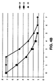
- Figure 4B shows the evolution of the thickness of the wall of the part that is obtained in each step in millimeters
- Figure 4C shows the evolution of the total length of the part that is obtained in each step in millimeters.
- Table 2 Evolution of the diameter of the part obtained in each step of the process EVOLUTION OF THE DIAMETER IN mm step 0 1 2 3 4 5 6 7 non-combined solution (14) 228 128.18 122.8 117.6 114.21 112.02 110.62 110.6 optimized combined solution (15) 228 194.8 167.2 144.9 126.3 110.6 experimental result (16) 228 195.5 167.7 145.5 126.7 110.8
- Table 3 Evolution of the thickness of the wall of the part obtained in each step of the process EVOLUTION OF THE THICKNESS OF THE WALL IN mm step 0 1 2 3 4 5 6 7 non-combined solution (14) 7.3 7.3 7.3 4.7 3.01 1.91 1.21 1.2 optimized combined solution (15) 7.3 5.16 3.4 2.3 1.6 1.2 experimental result (16) 7.3 5.35 3.35 2.1 1.52 1.15
- Table 4 Evolution of the length of the part obtained in each step of the process EVO
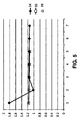
- the drawing ratio (DR) has similar values for the five stages designed, which shows a much more balanced process compared with the initial solution.
- the highest drawing ratios (DR) obtained in the first phases of the initial design (14) are reduced in the combined process (15).
- Table 5 Evolution of the drawing ratio (DR) in each step of the process EVOLUTION OF THE DRAWING RATIO IN EACH STEP step 1 2 3 4 5 6 7 non-combined solution (14) 1.8215 1.0194 1.1706 1.1651 1.1539 1.1471 1.1418 optimized combined solution (15) 1.1706 1.1651 1.1539 1.1471 1.1418 experimental result (16) 1.1662 1.1658 1.1526 1.1484 1.1435
- Figure 6 depicts a flowchart of all the operations carried out in an embodiment of an optimized combined simulation process:
- the optimization stage is optional and can be applied in the event of needing a combined process the parameters of which must be optimized to reduce the overall work performed.
Landscapes
- Engineering & Computer Science (AREA)
- Mechanical Engineering (AREA)
- General Engineering & Computer Science (AREA)
- Theoretical Computer Science (AREA)
- Physics & Mathematics (AREA)
- Manufacturing & Machinery (AREA)
- Computer Hardware Design (AREA)
- Evolutionary Computation (AREA)
- Geometry (AREA)
- General Physics & Mathematics (AREA)
- Shaping Metal By Deep-Drawing, Or The Like (AREA)
- Forging (AREA)
- Metal Extraction Processes (AREA)
- Extrusion Of Metal (AREA)
- Heat Treatment Of Steel (AREA)
Applications Claiming Priority (2)
| Application Number | Priority Date | Filing Date | Title |
|---|---|---|---|
| ES201230585A ES2426319B1 (es) | 2012-04-19 | 2012-04-19 | Proceso y sistema de conformado de una lámina metálica |
| PCT/ES2013/070249 WO2013156656A1 (es) | 2012-04-19 | 2013-04-18 | Proceso y sistema de conformado de una lámina metálica |
Publications (2)
| Publication Number | Publication Date |
|---|---|
| EP2842650A1 EP2842650A1 (en) | 2015-03-04 |
| EP2842650B1 true EP2842650B1 (en) | 2016-08-24 |
Family
ID=48699042
Family Applications (1)
| Application Number | Title | Priority Date | Filing Date |
|---|---|---|---|
| EP13731351.6A Active EP2842650B1 (en) | 2012-04-19 | 2013-04-18 | Sheet metal forming process and system |
Country Status (7)
| Country | Link |
|---|---|
| US (1) | US9908164B2 (https=) |
| EP (1) | EP2842650B1 (https=) |
| CN (1) | CN104364028B (https=) |
| CA (1) | CA2870815A1 (https=) |
| ES (2) | ES2426319B1 (https=) |
| IN (1) | IN2014DN09711A (https=) |
| WO (1) | WO2013156656A1 (https=) |
Families Citing this family (13)
| Publication number | Priority date | Publication date | Assignee | Title |
|---|---|---|---|---|
| US10894283B2 (en) * | 2016-02-24 | 2021-01-19 | Nisshin Steel Co., Ltd. | Molded material production method and molded material |
| US10850584B2 (en) * | 2016-06-07 | 2020-12-01 | Beijingwest Industries Co., Ltd. | Damper housing and a method for manufacturing the damper housing |
| JP6787013B2 (ja) | 2016-10-03 | 2020-11-18 | 日本製鉄株式会社 | 成形材製造方法 |
| CN107081365A (zh) * | 2017-06-06 | 2017-08-22 | 扬州尼尔工程塑料有限公司 | 一种新型的复杂薄壁构件拉深载荷控制方法 |
| CN109201816B (zh) * | 2017-09-07 | 2020-06-12 | 中国航空制造技术研究院 | 一种制备均匀壁厚超塑成形构件的方法及系统 |
| WO2020074597A1 (en) | 2018-10-12 | 2020-04-16 | Jt International S.A. | Aerosol generation device, and heating chamber therefor |
| CN111482515B (zh) * | 2020-03-27 | 2021-12-21 | 江苏大学 | 一种高强铝合金圆筒形深冲件模具及配套挤-拉-淬工艺 |
| CN112427562B (zh) * | 2020-11-02 | 2023-09-26 | 中材科技(成都)有限公司 | 一种压力容器钢质内胆的卧式冷拉深设备及其冷拉深方法 |
| CN113770243A (zh) * | 2021-09-10 | 2021-12-10 | 大连理工大学 | 极小圆角半径深腔薄壁金属构件的成形方法 |
| CN114939616A (zh) * | 2022-05-05 | 2022-08-26 | 江苏易实精密科技股份有限公司 | 一种高压泵密封圈支撑套的拉伸工艺 |
| CN117113694B (zh) * | 2023-08-28 | 2025-07-01 | 哈尔滨工业大学 | 一种精确预测热拉深气胀成形零件厚度的方法 |
| CN117910286B (zh) * | 2024-03-20 | 2024-07-16 | 季华实验室 | 压力自动计算方法、钣金件加工方法及相关设备 |
| CN120644551B (zh) * | 2025-06-04 | 2026-04-03 | 江苏普正精密科技有限公司 | 新能源动力电池壳体拉深成形工艺参数优化的方法 |
Family Cites Families (20)
| Publication number | Priority date | Publication date | Assignee | Title |
|---|---|---|---|---|
| US2915424A (en) * | 1952-11-05 | 1959-12-01 | Lyon George Albert | Method of making cartridge cases and like articles |
| US3058195A (en) * | 1958-11-17 | 1962-10-16 | Svenska Metallverken Ab | Method for the manufacture from sheet metal of hollow objects having a wall thickness in the closed end exceeding the wall thickness of the starting material |
| GB1136500A (en) * | 1966-10-15 | 1968-12-11 | Webster Ltd Edward | Improvements relating to the manufacture of thin-walled cylindrical articles |
| SE351377B (https=) * | 1967-04-20 | 1972-11-27 | Asea Ab | |
| DE1933483A1 (de) * | 1968-07-12 | 1970-02-05 | Press Und Stanzwerk Ag | Verfahren zur Herstellung von Patronenhuelsen |
| FR2154359B1 (https=) * | 1971-10-01 | 1976-02-13 | Pont S Sambre Ateliers Mecaniq | |
| US4038859A (en) | 1976-07-14 | 1977-08-02 | American Can Company | Metal forming die |
| CH602208A5 (https=) * | 1976-09-29 | 1978-07-31 | Km Engineering Ag | |
| JPS53133570A (en) | 1977-04-28 | 1978-11-21 | Kyodo Printing Co Ltd | Manufacturing method of compound tube |
| US4296536A (en) * | 1980-07-25 | 1981-10-27 | Reagent Chemical And Research, Inc. | Method of manufacturing cartridge cases |
| US4412440A (en) * | 1981-02-13 | 1983-11-01 | American Can Company | Process for making container |
| JPS63194824A (ja) * | 1987-02-07 | 1988-08-12 | Asahi Seiki Kogyo Kk | プレス成形部品 |
| NL1010009C2 (nl) | 1998-09-04 | 2000-03-07 | Hoogovens Staal Bv | Werkwijze voor de vervaardiging van in hoofdzaak metalen blanks, van busrompen uit zulke blanks, van gevulde en gesloten bussen uit dergelijke busrompen, alsmede een metalen busromp. |
| KR100432616B1 (ko) * | 1998-12-29 | 2004-09-13 | 주식회사 포스코 | 드로잉-아이어닝복합가공법에의한2피이스캔제조방법 |
| DE20122802U1 (de) | 2000-05-11 | 2008-09-11 | Autoform Engineering Gmbh | Computerlesbares Medium mit Programm zur Erzeugung von Ankonstruktionen von Werkzeugen für Blechumformteile |
| EP1347519A4 (en) | 2000-12-26 | 2007-05-02 | Matsushita Electric Industrial Co Ltd | QUADRATED BATTERY CONTAINER, METHOD FOR PRODUCING THE CONTAINER AND QUADRATED BATTERY USING THE CONTAINER |
| WO2003035298A1 (en) * | 2001-10-26 | 2003-05-01 | Aalborg Universitet | A die for simultaneous deep drawing and ironing processes, a product produced by use of such die and a method for producing such product |
| MXPA06010835A (es) * | 2004-03-26 | 2006-12-15 | Starck H C Inc | Crisoles de metales refractarios. |
| JP5019720B2 (ja) * | 2005-05-24 | 2012-09-05 | 小島プレス工業株式会社 | 電池ケースの製造装置 |
| JP2007027046A (ja) * | 2005-07-21 | 2007-02-01 | Matsushita Electric Ind Co Ltd | 電池缶およびその製造方法 |
-
2012
- 2012-04-19 ES ES201230585A patent/ES2426319B1/es not_active Expired - Fee Related
-
2013
- 2013-04-18 CA CA2870815A patent/CA2870815A1/en not_active Abandoned
- 2013-04-18 WO PCT/ES2013/070249 patent/WO2013156656A1/es not_active Ceased
- 2013-04-18 US US14/395,098 patent/US9908164B2/en not_active Expired - Fee Related
- 2013-04-18 CN CN201380027649.6A patent/CN104364028B/zh not_active Expired - Fee Related
- 2013-04-18 ES ES13731351.6T patent/ES2611338T3/es active Active
- 2013-04-18 EP EP13731351.6A patent/EP2842650B1/en active Active
-
2014
- 2014-11-18 IN IN9711DEN2014 patent/IN2014DN09711A/en unknown
Also Published As
| Publication number | Publication date |
|---|---|
| WO2013156656A9 (es) | 2014-04-10 |
| EP2842650A1 (en) | 2015-03-04 |
| ES2426319B1 (es) | 2014-09-02 |
| ES2426319R1 (es) | 2013-12-23 |
| CN104364028B (zh) | 2017-12-15 |
| WO2013156656A1 (es) | 2013-10-24 |
| ES2611338T3 (es) | 2017-05-08 |
| IN2014DN09711A (https=) | 2015-07-31 |
| US20150082853A1 (en) | 2015-03-26 |
| CA2870815A1 (en) | 2013-10-24 |
| US9908164B2 (en) | 2018-03-06 |
| ES2426319A2 (es) | 2013-10-22 |
| CN104364028A (zh) | 2015-02-18 |
Similar Documents
| Publication | Publication Date | Title |
|---|---|---|
| EP2842650B1 (en) | Sheet metal forming process and system | |
| Koc et al. | Prediction of forming limits and parameters in the tube hydroforming process | |
| Dhaiban et al. | Finite element modeling and experimental results of brass elliptic cups using a new deep drawing process through conical dies | |
| GB2445226A (en) | Multistage superplastic sheet forming with two sided die contact during first step | |
| Huang et al. | The multi-objective robust optimization of the loading path in the T-shape tube hydroforming based on dual response surface model | |
| JP2016511151A (ja) | 多段チューブハイドロフォーミング工程 | |
| EP3747566B1 (en) | Press-forming method, press-forming system, and press-formed product | |
| Dhaiban et al. | Development of deep drawing without blank-holder for producing elliptic brass cups through conical dies | |
| Mirzaali et al. | Optimization of tube hydroforming process using simulated annealing algorithm | |
| EP2837439A2 (en) | A method of reducing wrinkles in pressed sheet metal components | |
| Hassan et al. | Deep drawing of asymmetric cups through conical die without blank holder | |
| Zhang et al. | Shell element simulation of the push method of tube bending | |
| CN109803773A (zh) | 用于生产具有尺寸精确的侧板区域的成型构件的方法 | |
| Poor et al. | A novel approach in manufacturing two-stepped tubes using a multi-stage die in tube hydroforming process | |
| Djavanroodi et al. | Analytical and numerical analysis of free bulge tube hydroforming | |
| Padamurthy et al. | A review on analytical models for predicting forming force in incremental forming processes | |
| Hassan et al. | A developed process for increasing deep drawability of rectangular metal cups with extreme aspect ratio: finite element simulation | |
| Gaikwad et al. | Theoretical study on cold open die forging process optimization for multipass workability | |
| Hsieh et al. | Sheet-Metal Formability Study on a Circular Tube with a Folding Bottom Feature | |
| Van et al. | Optimizing blank geometry for die-less hydroforming of spherical parts | |
| Paunoiu et al. | Numerical study of tube hydroforming technology | |
| Yogeshbhai et al. | INVESTIGATION OF PUNCHING PROCESS USING STEEL AND ALUMINIUM ALLOYS | |
| Ekici et al. | Draw bead geometry optimization on springback of sheet forming | |
| CN120325779A (zh) | 一种厚板钛合金的变温拉深-快速气胀复合成形方法 | |
| Nhaichaniya et al. | Advanced Sheet Metal Forming Using Finite Element Analysis |
Legal Events
| Date | Code | Title | Description |
|---|---|---|---|
| PUAI | Public reference made under article 153(3) epc to a published international application that has entered the european phase |
Free format text: ORIGINAL CODE: 0009012 |
|
| 17P | Request for examination filed |
Effective date: 20141119 |
|
| AK | Designated contracting states |
Kind code of ref document: A1 Designated state(s): AL AT BE BG CH CY CZ DE DK EE ES FI FR GB GR HR HU IE IS IT LI LT LU LV MC MK MT NL NO PL PT RO RS SE SI SK SM TR |
|
| AX | Request for extension of the european patent |
Extension state: BA ME |
|
| GRAP | Despatch of communication of intention to grant a patent |
Free format text: ORIGINAL CODE: EPIDOSNIGR1 |
|
| INTG | Intention to grant announced |
Effective date: 20160302 |
|
| GRAS | Grant fee paid |
Free format text: ORIGINAL CODE: EPIDOSNIGR3 |
|
| GRAA | (expected) grant |
Free format text: ORIGINAL CODE: 0009210 |
|
| AK | Designated contracting states |
Kind code of ref document: B1 Designated state(s): AL AT BE BG CH CY CZ DE DK EE ES FI FR GB GR HR HU IE IS IT LI LT LU LV MC MK MT NL NO PL PT RO RS SE SI SK SM TR |
|
| AX | Request for extension of the european patent |
Extension state: BA ME |
|
| REG | Reference to a national code |
Ref country code: GB Ref legal event code: FG4D |
|
| REG | Reference to a national code |
Ref country code: CH Ref legal event code: EP |
|
| REG | Reference to a national code |
Ref country code: AT Ref legal event code: REF Ref document number: 822599 Country of ref document: AT Kind code of ref document: T Effective date: 20160915 |
|
| REG | Reference to a national code |
Ref country code: IE Ref legal event code: FG4D |
|
| REG | Reference to a national code |
Ref country code: DE Ref legal event code: R096 Ref document number: 602013010643 Country of ref document: DE |
|
| REG | Reference to a national code |
Ref country code: LT Ref legal event code: MG4D |
|
| REG | Reference to a national code |
Ref country code: NL Ref legal event code: MP Effective date: 20160824 |
|
| REG | Reference to a national code |
Ref country code: AT Ref legal event code: MK05 Ref document number: 822599 Country of ref document: AT Kind code of ref document: T Effective date: 20160824 |
|
| PG25 | Lapsed in a contracting state [announced via postgrant information from national office to epo] |
Ref country code: FI Free format text: LAPSE BECAUSE OF FAILURE TO SUBMIT A TRANSLATION OF THE DESCRIPTION OR TO PAY THE FEE WITHIN THE PRESCRIBED TIME-LIMIT Effective date: 20160824 Ref country code: NO Free format text: LAPSE BECAUSE OF FAILURE TO SUBMIT A TRANSLATION OF THE DESCRIPTION OR TO PAY THE FEE WITHIN THE PRESCRIBED TIME-LIMIT Effective date: 20161124 Ref country code: RS Free format text: LAPSE BECAUSE OF FAILURE TO SUBMIT A TRANSLATION OF THE DESCRIPTION OR TO PAY THE FEE WITHIN THE PRESCRIBED TIME-LIMIT Effective date: 20160824 Ref country code: IT Free format text: LAPSE BECAUSE OF FAILURE TO SUBMIT A TRANSLATION OF THE DESCRIPTION OR TO PAY THE FEE WITHIN THE PRESCRIBED TIME-LIMIT Effective date: 20160824 Ref country code: HR Free format text: LAPSE BECAUSE OF FAILURE TO SUBMIT A TRANSLATION OF THE DESCRIPTION OR TO PAY THE FEE WITHIN THE PRESCRIBED TIME-LIMIT Effective date: 20160824 Ref country code: LT Free format text: LAPSE BECAUSE OF FAILURE TO SUBMIT A TRANSLATION OF THE DESCRIPTION OR TO PAY THE FEE WITHIN THE PRESCRIBED TIME-LIMIT Effective date: 20160824 Ref country code: NL Free format text: LAPSE BECAUSE OF FAILURE TO SUBMIT A TRANSLATION OF THE DESCRIPTION OR TO PAY THE FEE WITHIN THE PRESCRIBED TIME-LIMIT Effective date: 20160824 |
|
| PG25 | Lapsed in a contracting state [announced via postgrant information from national office to epo] |
Ref country code: LV Free format text: LAPSE BECAUSE OF FAILURE TO SUBMIT A TRANSLATION OF THE DESCRIPTION OR TO PAY THE FEE WITHIN THE PRESCRIBED TIME-LIMIT Effective date: 20160824 Ref country code: GR Free format text: LAPSE BECAUSE OF FAILURE TO SUBMIT A TRANSLATION OF THE DESCRIPTION OR TO PAY THE FEE WITHIN THE PRESCRIBED TIME-LIMIT Effective date: 20161125 Ref country code: AT Free format text: LAPSE BECAUSE OF FAILURE TO SUBMIT A TRANSLATION OF THE DESCRIPTION OR TO PAY THE FEE WITHIN THE PRESCRIBED TIME-LIMIT Effective date: 20160824 Ref country code: SE Free format text: LAPSE BECAUSE OF FAILURE TO SUBMIT A TRANSLATION OF THE DESCRIPTION OR TO PAY THE FEE WITHIN THE PRESCRIBED TIME-LIMIT Effective date: 20160824 Ref country code: PT Free format text: LAPSE BECAUSE OF FAILURE TO SUBMIT A TRANSLATION OF THE DESCRIPTION OR TO PAY THE FEE WITHIN THE PRESCRIBED TIME-LIMIT Effective date: 20161226 |
|
| REG | Reference to a national code |
Ref country code: FR Ref legal event code: PLFP Year of fee payment: 5 |
|
| PG25 | Lapsed in a contracting state [announced via postgrant information from national office to epo] |
Ref country code: EE Free format text: LAPSE BECAUSE OF FAILURE TO SUBMIT A TRANSLATION OF THE DESCRIPTION OR TO PAY THE FEE WITHIN THE PRESCRIBED TIME-LIMIT Effective date: 20160824 Ref country code: RO Free format text: LAPSE BECAUSE OF FAILURE TO SUBMIT A TRANSLATION OF THE DESCRIPTION OR TO PAY THE FEE WITHIN THE PRESCRIBED TIME-LIMIT Effective date: 20160824 |
|
| REG | Reference to a national code |
Ref country code: ES Ref legal event code: FG2A Ref document number: 2611338 Country of ref document: ES Kind code of ref document: T3 Effective date: 20170508 |
|
| REG | Reference to a national code |
Ref country code: DE Ref legal event code: R097 Ref document number: 602013010643 Country of ref document: DE |
|
| PG25 | Lapsed in a contracting state [announced via postgrant information from national office to epo] |
Ref country code: SK Free format text: LAPSE BECAUSE OF FAILURE TO SUBMIT A TRANSLATION OF THE DESCRIPTION OR TO PAY THE FEE WITHIN THE PRESCRIBED TIME-LIMIT Effective date: 20160824 Ref country code: DK Free format text: LAPSE BECAUSE OF FAILURE TO SUBMIT A TRANSLATION OF THE DESCRIPTION OR TO PAY THE FEE WITHIN THE PRESCRIBED TIME-LIMIT Effective date: 20160824 Ref country code: CZ Free format text: LAPSE BECAUSE OF FAILURE TO SUBMIT A TRANSLATION OF THE DESCRIPTION OR TO PAY THE FEE WITHIN THE PRESCRIBED TIME-LIMIT Effective date: 20160824 Ref country code: SM Free format text: LAPSE BECAUSE OF FAILURE TO SUBMIT A TRANSLATION OF THE DESCRIPTION OR TO PAY THE FEE WITHIN THE PRESCRIBED TIME-LIMIT Effective date: 20160824 Ref country code: PL Free format text: LAPSE BECAUSE OF FAILURE TO SUBMIT A TRANSLATION OF THE DESCRIPTION OR TO PAY THE FEE WITHIN THE PRESCRIBED TIME-LIMIT Effective date: 20160824 Ref country code: BE Free format text: LAPSE BECAUSE OF FAILURE TO SUBMIT A TRANSLATION OF THE DESCRIPTION OR TO PAY THE FEE WITHIN THE PRESCRIBED TIME-LIMIT Effective date: 20160824 Ref country code: BG Free format text: LAPSE BECAUSE OF FAILURE TO SUBMIT A TRANSLATION OF THE DESCRIPTION OR TO PAY THE FEE WITHIN THE PRESCRIBED TIME-LIMIT Effective date: 20161124 |
|
| PLBE | No opposition filed within time limit |
Free format text: ORIGINAL CODE: 0009261 |
|
| STAA | Information on the status of an ep patent application or granted ep patent |
Free format text: STATUS: NO OPPOSITION FILED WITHIN TIME LIMIT |
|
| 26N | No opposition filed |
Effective date: 20170526 |
|
| PG25 | Lapsed in a contracting state [announced via postgrant information from national office to epo] |
Ref country code: SI Free format text: LAPSE BECAUSE OF FAILURE TO SUBMIT A TRANSLATION OF THE DESCRIPTION OR TO PAY THE FEE WITHIN THE PRESCRIBED TIME-LIMIT Effective date: 20160824 |
|
| REG | Reference to a national code |
Ref country code: IE Ref legal event code: MM4A |
|
| PG25 | Lapsed in a contracting state [announced via postgrant information from national office to epo] |
Ref country code: MC Free format text: LAPSE BECAUSE OF FAILURE TO SUBMIT A TRANSLATION OF THE DESCRIPTION OR TO PAY THE FEE WITHIN THE PRESCRIBED TIME-LIMIT Effective date: 20160824 |
|
| PG25 | Lapsed in a contracting state [announced via postgrant information from national office to epo] |
Ref country code: LU Free format text: LAPSE BECAUSE OF NON-PAYMENT OF DUE FEES Effective date: 20170418 |
|
| REG | Reference to a national code |
Ref country code: FR Ref legal event code: PLFP Year of fee payment: 6 |
|
| PG25 | Lapsed in a contracting state [announced via postgrant information from national office to epo] |
Ref country code: IE Free format text: LAPSE BECAUSE OF NON-PAYMENT OF DUE FEES Effective date: 20170418 |
|
| PG25 | Lapsed in a contracting state [announced via postgrant information from national office to epo] |
Ref country code: MT Free format text: LAPSE BECAUSE OF NON-PAYMENT OF DUE FEES Effective date: 20170418 |
|
| PG25 | Lapsed in a contracting state [announced via postgrant information from national office to epo] |
Ref country code: AL Free format text: LAPSE BECAUSE OF FAILURE TO SUBMIT A TRANSLATION OF THE DESCRIPTION OR TO PAY THE FEE WITHIN THE PRESCRIBED TIME-LIMIT Effective date: 20160824 |
|
| PG25 | Lapsed in a contracting state [announced via postgrant information from national office to epo] |
Ref country code: HU Free format text: LAPSE BECAUSE OF FAILURE TO SUBMIT A TRANSLATION OF THE DESCRIPTION OR TO PAY THE FEE WITHIN THE PRESCRIBED TIME-LIMIT; INVALID AB INITIO Effective date: 20130418 |
|
| PG25 | Lapsed in a contracting state [announced via postgrant information from national office to epo] |
Ref country code: CY Free format text: LAPSE BECAUSE OF FAILURE TO SUBMIT A TRANSLATION OF THE DESCRIPTION OR TO PAY THE FEE WITHIN THE PRESCRIBED TIME-LIMIT Effective date: 20160824 |
|
| PG25 | Lapsed in a contracting state [announced via postgrant information from national office to epo] |
Ref country code: MK Free format text: LAPSE BECAUSE OF FAILURE TO SUBMIT A TRANSLATION OF THE DESCRIPTION OR TO PAY THE FEE WITHIN THE PRESCRIBED TIME-LIMIT Effective date: 20160824 |
|
| PG25 | Lapsed in a contracting state [announced via postgrant information from national office to epo] |
Ref country code: TR Free format text: LAPSE BECAUSE OF FAILURE TO SUBMIT A TRANSLATION OF THE DESCRIPTION OR TO PAY THE FEE WITHIN THE PRESCRIBED TIME-LIMIT Effective date: 20160824 |
|
| PG25 | Lapsed in a contracting state [announced via postgrant information from national office to epo] |
Ref country code: IS Free format text: LAPSE BECAUSE OF FAILURE TO SUBMIT A TRANSLATION OF THE DESCRIPTION OR TO PAY THE FEE WITHIN THE PRESCRIBED TIME-LIMIT Effective date: 20161224 |
|
| PGFP | Annual fee paid to national office [announced via postgrant information from national office to epo] |
Ref country code: ES Payment date: 20200522 Year of fee payment: 8 Ref country code: CH Payment date: 20200504 Year of fee payment: 8 Ref country code: DE Payment date: 20200429 Year of fee payment: 8 Ref country code: FR Payment date: 20200427 Year of fee payment: 8 |
|
| PGFP | Annual fee paid to national office [announced via postgrant information from national office to epo] |
Ref country code: GB Payment date: 20200427 Year of fee payment: 8 |
|
| REG | Reference to a national code |
Ref country code: DE Ref legal event code: R119 Ref document number: 602013010643 Country of ref document: DE |
|
| GBPC | Gb: european patent ceased through non-payment of renewal fee |
Effective date: 20210418 |
|
| PG25 | Lapsed in a contracting state [announced via postgrant information from national office to epo] |
Ref country code: GB Free format text: LAPSE BECAUSE OF NON-PAYMENT OF DUE FEES Effective date: 20210418 Ref country code: FR Free format text: LAPSE BECAUSE OF NON-PAYMENT OF DUE FEES Effective date: 20210430 Ref country code: DE Free format text: LAPSE BECAUSE OF NON-PAYMENT OF DUE FEES Effective date: 20211103 Ref country code: CH Free format text: LAPSE BECAUSE OF NON-PAYMENT OF DUE FEES Effective date: 20210430 Ref country code: LI Free format text: LAPSE BECAUSE OF NON-PAYMENT OF DUE FEES Effective date: 20210430 |
|
| REG | Reference to a national code |
Ref country code: ES Ref legal event code: FD2A Effective date: 20220729 |
|
| PG25 | Lapsed in a contracting state [announced via postgrant information from national office to epo] |
Ref country code: ES Free format text: LAPSE BECAUSE OF NON-PAYMENT OF DUE FEES Effective date: 20210419 |