EP2841663B1 - Device for covering a building structure and structure covered by such a device - Google Patents
Device for covering a building structure and structure covered by such a device Download PDFInfo
- Publication number
- EP2841663B1 EP2841663B1 EP13721619.8A EP13721619A EP2841663B1 EP 2841663 B1 EP2841663 B1 EP 2841663B1 EP 13721619 A EP13721619 A EP 13721619A EP 2841663 B1 EP2841663 B1 EP 2841663B1
- Authority
- EP
- European Patent Office
- Prior art keywords
- sheet
- accessory
- fasteners
- rod
- face
- Prior art date
- Legal status (The legal status is an assumption and is not a legal conclusion. Google has not performed a legal analysis and makes no representation as to the accuracy of the status listed.)
- Active
Links
Images


Classifications
-
- E—FIXED CONSTRUCTIONS
- E04—BUILDING
- E04F—FINISHING WORK ON BUILDINGS, e.g. STAIRS, FLOORS
- E04F13/00—Coverings or linings, e.g. for walls or ceilings
- E04F13/07—Coverings or linings, e.g. for walls or ceilings composed of covering or lining elements; Sub-structures therefor; Fastening means therefor
- E04F13/08—Coverings or linings, e.g. for walls or ceilings composed of covering or lining elements; Sub-structures therefor; Fastening means therefor composed of a plurality of similar covering or lining elements
- E04F13/0801—Separate fastening elements
- E04F13/0832—Separate fastening elements without load-supporting elongated furring elements between wall and covering elements
- E04F13/0833—Separate fastening elements without load-supporting elongated furring elements between wall and covering elements not adjustable
- E04F13/0835—Separate fastening elements without load-supporting elongated furring elements between wall and covering elements not adjustable the fastening elements extending into the back side of the covering elements
- E04F13/0837—Separate fastening elements without load-supporting elongated furring elements between wall and covering elements not adjustable the fastening elements extending into the back side of the covering elements extending completely through the covering elements
-
- E—FIXED CONSTRUCTIONS
- E04—BUILDING
- E04F—FINISHING WORK ON BUILDINGS, e.g. STAIRS, FLOORS
- E04F13/00—Coverings or linings, e.g. for walls or ceilings
- E04F13/07—Coverings or linings, e.g. for walls or ceilings composed of covering or lining elements; Sub-structures therefor; Fastening means therefor
- E04F13/08—Coverings or linings, e.g. for walls or ceilings composed of covering or lining elements; Sub-structures therefor; Fastening means therefor composed of a plurality of similar covering or lining elements
- E04F13/0862—Coverings or linings, e.g. for walls or ceilings composed of covering or lining elements; Sub-structures therefor; Fastening means therefor composed of a plurality of similar covering or lining elements composed of a number of elements which are identical or not, e.g. carried by a common web, support plate or grid
-
- E—FIXED CONSTRUCTIONS
- E04—BUILDING
- E04F—FINISHING WORK ON BUILDINGS, e.g. STAIRS, FLOORS
- E04F13/00—Coverings or linings, e.g. for walls or ceilings
- E04F13/07—Coverings or linings, e.g. for walls or ceilings composed of covering or lining elements; Sub-structures therefor; Fastening means therefor
- E04F13/08—Coverings or linings, e.g. for walls or ceilings composed of covering or lining elements; Sub-structures therefor; Fastening means therefor composed of a plurality of similar covering or lining elements
- E04F13/0871—Coverings or linings, e.g. for walls or ceilings composed of covering or lining elements; Sub-structures therefor; Fastening means therefor composed of a plurality of similar covering or lining elements having an ornamental or specially shaped visible surface
-
- E—FIXED CONSTRUCTIONS
- E04—BUILDING
- E04F—FINISHING WORK ON BUILDINGS, e.g. STAIRS, FLOORS
- E04F13/00—Coverings or linings, e.g. for walls or ceilings
- E04F13/07—Coverings or linings, e.g. for walls or ceilings composed of covering or lining elements; Sub-structures therefor; Fastening means therefor
- E04F13/08—Coverings or linings, e.g. for walls or ceilings composed of covering or lining elements; Sub-structures therefor; Fastening means therefor composed of a plurality of similar covering or lining elements
- E04F13/12—Coverings or linings, e.g. for walls or ceilings composed of covering or lining elements; Sub-structures therefor; Fastening means therefor composed of a plurality of similar covering or lining elements of metal or with an outer layer of metal or enameled metal
-
- E—FIXED CONSTRUCTIONS
- E04—BUILDING
- E04F—FINISHING WORK ON BUILDINGS, e.g. STAIRS, FLOORS
- E04F13/00—Coverings or linings, e.g. for walls or ceilings
- E04F13/07—Coverings or linings, e.g. for walls or ceilings composed of covering or lining elements; Sub-structures therefor; Fastening means therefor
- E04F13/08—Coverings or linings, e.g. for walls or ceilings composed of covering or lining elements; Sub-structures therefor; Fastening means therefor composed of a plurality of similar covering or lining elements
- E04F13/0801—Separate fastening elements
-
- F—MECHANICAL ENGINEERING; LIGHTING; HEATING; WEAPONS; BLASTING
- F16—ENGINEERING ELEMENTS AND UNITS; GENERAL MEASURES FOR PRODUCING AND MAINTAINING EFFECTIVE FUNCTIONING OF MACHINES OR INSTALLATIONS; THERMAL INSULATION IN GENERAL
- F16B—DEVICES FOR FASTENING OR SECURING CONSTRUCTIONAL ELEMENTS OR MACHINE PARTS TOGETHER, e.g. NAILS, BOLTS, CIRCLIPS, CLAMPS, CLIPS OR WEDGES; JOINTS OR JOINTING
- F16B5/00—Joining sheets or plates, e.g. panels, to one another or to strips or bars parallel to them
- F16B5/02—Joining sheets or plates, e.g. panels, to one another or to strips or bars parallel to them by means of fastening members using screw-thread
- F16B5/0275—Joining sheets or plates, e.g. panels, to one another or to strips or bars parallel to them by means of fastening members using screw-thread the screw-threaded element having at least two axially separated threaded portions
Definitions
- the invention relates to a wall covering device in a structure, of the type commonly used in the building under the name of cladding system.
- a structure of the type commonly used in the building under the name of cladding system.
- one or more outer faces of the building are coated with sheets or facing sheets, said cladding sheets. These sheets are attached to elements that are part of the load-bearing structure of the building or are reported on this structure.
- structure here means a frame, for example made by metal profiles or the continuous wall of a wall for example concrete, inside or outside, that this wall is vertical, horizontal or inclined.
- This is, for example, a partition wall, a load-bearing wall or a wall holding a slope.
- Structural members are also referred to in the roof of a building, whether the latter is for domestic or professional use.
- the cladding sheets in the known coating devices of this type are formed of plates or sheets of rigid material, for example metal sheets, fixed to the structure. Alternatively, it may be non-metallic plates, for example polymer, transparent or not, or composite material which is also referred to as "sheets" in what follows.
- These sheets are generally rectangular in shape and are provided with at least two parallel ribs distributed over two parallel edges of the sheet.
- the ribs are adapted to either cover or be covered by a similar rib of another sheet, when the sheets are placed side by side or butted.
- the partial overlapping of the sheets contributes to the waterproofing of the structure's coating.
- the fastening of the cladding sheets in the structure is carried out by screws or rivets driven into elements constituting the structure or intermediate elements reported on the structure, for example metal or wood, to arrange intervals in the thickness of the coated wall, for purposes of insulation, air circulation or passage of functional components, cables for example.
- screws or rivets driven into elements constituting the structure or intermediate elements reported on the structure for example metal or wood
- intervals in the thickness of the coated wall for purposes of insulation, air circulation or passage of functional components, cables for example.
- this fastening must be watertight to respect the insulation performance required by the regulations. It is generally performed by drilling the sheet during riveting or screwing into the structure. If necessary, a seal is provided at each rivet or screw for sealing.
- Said fixing means also comprise a holding means adapted to hold an intermediate member of the fixing means, fixed to the accessory, the holding means cooperating removably with the head of the rod of the fasteners.
- the object of the present invention is to propose an alternative solution, which, while being economical and mechanically efficient, makes it possible to vary the visual appearance or the functional properties of a coating sheet of a structure, where appropriate after the poses, according to the evolution of the aesthetic or functional needs, without calling into question the physical integrity and the own quality of the fixing of the sheet on the structure.
- the subject of the invention is a coating device as defined in claim 1.
- one of the ideas underlying the invention is to take advantage of the prior fasteners of the sheet metal on the structure so that a head of these fasteners forms, at least in part, means for fixing a or several accessories, suitable to affect neither the quality or the integrity, especially functional, of the binding between the sheet and the structure nor the sheet itself.
- This makes it possible to modify the appearance and / or certain functionalities of the coating of a building, to give it a modularity or to create patterns in panels coated according to this system.
- these fastening means of the accessory on the sheet can be adapted to achieve a removable attachment of the accessory which can be disassembled or reassembled without compromising the strength or integrity of the basic construction.
- the system makes it possible to respect the shapes or properties of a predetermined design, specific to each project, based on basic elements that may be the same. It also allows after the completion of the construction and its commissioning to add accessories and remove them, or to adapt to changes in use and various needs that may arise, for example in terms of signage or display or various features.
- the change of the accessory or accessories on the sheet, the addition of such elements can be done by avoiding any drilling or intrusive intervention in the sheet already in place or in its structure and the assembly means by which they are associated with mounting initial.
- the modification of the appearance of the structure is facilitated, the integrity, including sealing, of the attachment of the sheet to the structure is in any case preserved.
- the invention also extends to a building structure as defined in claim 14.
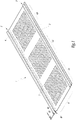
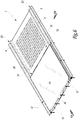
- the figure 1 illustrates a metal sheet 1 of rectangular shape, provided on two parallel edges 2, 3, defining the length of the sheet 1, ribs 4 and 5 parallel and open.
- These ribs 4, 5 have, in cross section, a shape in double S. In other words, they have, in cross section, two reliefs R1, R2 located above an average plane P of the sheet 1, on either side of a relief R3 located below the average plane P, looking at the figure 1 .
- the ribs have another shape, as shown, by way of non-limiting example, at the figure 16 on which the corresponding plate and its ribs are respectively referenced 1 ', 4' and 5 '.
- the ribs 4, 5 of the sheet 1 are here constitutive edges 2, 3. Alternatively, they are arranged according to the width of the sheet. In another variant, the ribs 4,5 do not define the edges of the sheet but occupy the central portion of the latter. In other embodiments, the sheet may be square.
- the space separating the two ribs 4, 5 delimits the main body 6 of the sheet 1.
- This body 6 is here provided with three groups G1, G2, G3 elongate reliefs 7 arranged parallel to each other. These reliefs 7 have, in cross section, a half-moon configuration. They extend between the ribs 4, 5, perpendicular to the latter.
- the main body 6 of the sheet 1 is flat or provided with ribs parallel to the edges 2, 3 or provided with reliefs of complex geometry, for example in the form of a half moon, sheet, star, wave, these reliefs being regularly distributed or not.
- the configuration and / or the number of reliefs 7 distributed on the body 6 are adapted to the desired visual appearance.
- An accessory 8, shown in figure 2 is adapted, if necessary, to be mounted on the sheet 1.
- This accessory 8 forms a support member. It is in the form of an elongated bar and configured as a rib 4 or 5, that is to say in cross section it has a double S shape, it being understood that this cross section can be of configuration different.
- the bar 8 is thus configured as a part of a rib 4 or 5. It is provided with at least one orifice, here three orifices 80 arranged in the middle part of the member, that is to say, aligned according to its larger dimension and arranged in the part of the accessory 8 corresponding to the relief R3 of a rib 4 or 5.
- the bar 8 has a length adapted to the width of the body 6 to be mounted on the body 6 perpendicular to the ribs 4 and 5 while being in contact, at its ends, with the flanks of the ribs 4 and 5, as can be seen at the figure 4 .
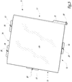
- FIG. figure 3 Another type of accessory 9 is shown in FIG. figure 3 . It is configured in a square plate, made of a rigid material, for example metal, polymer or wood.
- This plate 9, also called cassette, can be, on at least its face 10 intended to be visible when in position on a sheet 1, colored, tinted, printed or provided with reliefs of different shapes giving it a decorative appearance.
- it may be of a shape other than square, for example rectangular, pentagonal, octagonal or other.
- the plate 9 has its four folded sides, for example here at right angles, with respect to its face 10, thus forming four lips 11 to 14 angular with respect to the upper face 10 of the plate 9.
- the lips 11 to 14 are oriented to the sheet 1 when the plate 9 is in position on the latter.
- Elongated lugs 15 to 19 extend from the free ends of the lips 11 to 14 as is apparent from the figure 14 these legs are each integral with the lip from which they extend. These tabs are oriented towards the outside of the plate 9, parallel to the face 10. In other words, the tabs 15 to 19 extend outwardly, perpendicular to the lips 11 to 14.
- Each leg 15 to 19 is provided with at least one orifice 20, formed substantially in a central position for the tabs 16 to 19 and in the vicinity of one end for the tab 15.
- the tabs 15 to 19 are arranged differently on each lip.
- the tab 15 is fixed on one end of the lip which is close to one end of the lip 12.
- the lips 12 and 13 are equipped, in the central position, tabs 16, respectively 17.
- Two tabs 18 and 19 are, in turn, located in the vicinity of the ends of the lip 14.
- Such an arrangement of the tabs 15 to 19 makes it possible, when a plate 9 is positioned next to another identical plate 9, to bring two lips of the plates, the lugs 15 to 19 of which are offset relative to each other relative to one another. to the other, in order to minimize the space between the neighboring plates without the latter being so joined. In other words, there is no overlap of the legs 15 to 19 of two adjacent plates 9.
- the arrangement of the tabs is different, provided that this arrangement avoids overlap while minimizing the space between two adjacent plates.
- Permanently and tightly fastening fasteners for the sheet 1 on one face of a structure, not illustrated for greater clarity, are formed by threaded rods 21. These rods 21 are inserted into orifices passing through the sheet 1
- the orifices are either made in the factory or, preferably, on site. In this case, the rods are advantageously provided with a self-piercing tip.
- Some rods 21 are inserted at the portions R3 of the ribs 4 and 5, others in the body 6, or between two groups G1 to G3 of reliefs 7, or between two reliefs 7 of the same group G1 to G3.
- the number and the distribution of the fastening means 21 of the sheets on the structure depend on the criteria of the overlap between the sheets 1, the dimensions of the sheets 1 and the mounting conditions, for example the wind resistance imposed by the regulations or the weight accessories to be supported by the sheet 1.
- the sealing of the attachment of the sheet 1 to the structure is achieved, for example, by a seal.
- the distribution of the rods 21 on the sheet 1 is identified by a pictogram, a precut, a raised marking, using templates provided with the sheet or by any other known locating means.
- the rods 21 are dual function fasteners.
- the rods 21 comprise a portion adapted to maintain, in a sealed manner, a sheet 1 on a structure.
- This part includes, as it appears more clearly in the figure 14 , a threaded portion 210 located in the vicinity of the tip 211 of the rod 21.
- the support of the sheet 1 on the structure is obtained by a flange 212, secured to the rod 21.
- This flange 212 is placed in the vicinity of the end of the thread opposite to the tip 211. In other words, the flange 212 materializes the separation between the threaded portion 210 and the head 213 of the rod 21.
- the head 213 is provided with an external thread and a fingerprint
- This imprint 214 advantageously makes it possible to drive the rod 21 in rotation, more generally to maneuver this rod, in order to fix its portion 210 in the structure.
- a seal is advantageously provided under the flange 212 and around the threaded portion 210.
- the head 213 forms a means for attaching an accessory to the sheet 1.
- the bars or support members 8 are thus mounted removably on the sheet 1.
- the heads 213 of some rods 21 are inserted into the orifices 80 of the bars 8. They thus make it possible to maintain, removably, the bars 8 resting on the sheet 1 by means of nuts 22, screwed onto the heads 214.
- These nuts 22 are blind and used as a protective cover of the heads 213 of the rods 21 on all of the rods 21 which ensure the attachment of the sheet 1 to the structure, as shown in FIG. figure 4 .
- the nuts 22 are here circular cylindrical. They are provided with three operating notches 220, arranged parallel to a longitudinal axis of each nut 22. These grooves 220 form actuating members, with the aid of a suitable tool, of a nut 22.
- the accessories 8 are thus fixed on the sheet 1 without altering the tightness of the attachment of the sheet 1 to the structure and without modifying the structural integrity of the sheet 1, for example by drilling.
- the detachable and sealed fastening means respectively of the bar 8 on the sheet 1 and the sheet 1 on the structure, are formed by a single member, namely a threaded rod 21, combined with the nut 22.
- the figure 5 illustrates the mounting of the accessory plate 9, illustrated in FIG. figure 3 , on a sheet 1 illustrated at figure 1 .
- the plate 9 is in a position where the tabs 15 and 16 are visible.
- the tab 15 is positioned above the relief R3 of the rib 5 and the lug 16 above the main body 6 of the sheet 1.
- the orifices 20 of the lugs 15 and 16 allow the heads 214 to pass through two rods 21 mounted for one in the rib 5 and the other in the body 6.
- the tabs allow the fixing of the plate 9 on the sheet 1, at the lateral ribs 4, 5 and at the level of the flat areas 70 located between groups G1 to G3 of reliefs 7.
- the receiving zone Z of the accessory is delimited between, on the one hand, the ribs 4, 5 and, on the other hand, two plane zones 70 located on either side of the a group G2 of reliefs 7.
- the figure 6 is a plate 9 when removably attached to the plate 1.
- the attachment is similar to that of a bar 8 on the plate 1.
- the tabs 15 to 19 are positioned so that the orifices 20 of each tab receives a head 213 of a rod 21.
- the nuts 22 have dimensions such that, when they are in place on the heads 213, they hold the tabs 15, 16 of the plate 9 against the plate 1.
- the lips 11 and 13 are supported, on the bottom of the reliefs R3 of the ribs 5 and 4.
- the lips 12 and 14 are supported on the flat areas 70, on either side of a group of reliefs 7.
- the dimensions of the plate 9, the ribs 4 and 5 and the sheet 1 are that the extra thickness due to the introduction of the plate 9 is minimal, as is apparent from the Figures 7 and 8 .
- cleaning is effected by fixing the plate 9 on the sheet 1 a space E between the plate 9 and the body 6 allowing, if necessary, the establishment of a insulation or the passage of cables and / or ducts.
- the visual appearance of the sheet 1 is modified, only the face 10 of the plate 9 being visible. It is understood that several plates 9 may, as desired, be mounted on the sheet 1.
- the mechanical behavior and strength of the sheet 1 are not or slightly affected by the mounting of the plate or plates 9 to the extent that no drilling or cutting must be done in sheet 1.
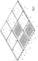
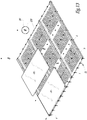
- the figure 9 illustrates three plates 1 assembled by partial overlap of their ribs 4 and 5 and intended to cover part of a structure, not shown. Plates 9 are fixed on all or part of each sheet 1. In this case, the sheet 1 located on the left looking at the figure 9 is entirely covered with plates 9, the plate 1 on the right is provided, on two thirds of its surface, with plates 9 and the central plate 1 is equipped only with a plate 9.
- the percentage of coverage of the plates 1 by the plates 9 and the distribution of the latter on the plates 1 is chosen. It is noted that the faces 10 of the plates 9 are coplanar but not contiguous. One day, whose width substantially corresponds to the width of the tabs 15 to 19, is formed between two adjacent plates 9.
- the arrangement of the tabs 15 to 19 on the lips 11 to 14 allows, when two plates 9 are side by side, that their lugs 15 to 19 respectively interpose and do not overlap. We thus provide a zone of juxtaposition between two plates 9 rectilinear and homogeneous, without excess thickness, the tabs 15 to 19 of the two plates being intercalated to be in the extension of each other in a direction parallel to the faces 10 of these plates.
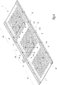
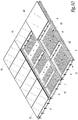
- the figure 10 is obtained by juxtaposition of three sheets 1 according to the figure 4 .
- the figure 10 illustrates another embodiment of the invention in which the accessories comprise decorative facing plates 90 without legs and rectangular plates 91, also without tabs.
- the plates 90, 91 are mounted on three plates 1 assembled by partial overlapping using Z-section bars 8, which in this example have an additional utility role. These bars are spacers that play a role of support or adapters of ancillary materials and which are fixed on the sheet as the other accessories of the invention.
- the plates 90, 91 are received on a reception zone Z1 delimited by two bars 8 and the ribs 4, 5.
- each plate 90 or 91 is fixed on the bars 8 themselves fixed on the body 6, as illustrated in FIG. figure 4 .
- Such a solution allows the visible faces of the plates 90 and 91 to be joined.
- the fixing of the plates 90, 91 is done, for example, by screwing on the accessories 8.
- the attachment is performed by a system of clips or, in the case of a final fixing, by gluing or welding. In such a configuration, it is the accessory assembly 8 and plates 90 or 91 which is removable, not a plate 90, 91 alone.
- Each plate 9, 90, 91 is advantageously mounted, removably, both at the ribs 4, 5 and accessories 8.
- the accessory it is possible to change the accessory as necessary, it can be a plate 9, 90, 91 colored, carrying a graphic, decorative reliefs or printing.
- this accessory may be a stage of a projector, a mounting plate for a loudspeaker type speaker, a mounting plate for a flowerpot or a planter, a mounting plate for a embossed letter or other accessories provided that this accessory, or at least the part of the accessory intended to be fixed on the sheet, has a shape compatible with the geometric configuration of the sheet 1 and, advantageously, is provided with orifices 20, the latter being preferentially drilled in the factory.
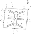
- an accessory 92 is shown with a shape and dimensions similar to those of the plate 9.
- This accessory is in the form of a plate 92, hereinafter called "Cassette”, and equipped, not only fastening means on the sheet 1, namely tabs 15 to 19, identical to those of the plate 9, but also own fastening means that allow to fix, removably, one or more element (s) on the plate 92, for example a projector, an enclosure, a flowerpot, a planter, the raised letter, or a plate 90, 91.
- These means include, on a face 93 of the cassette 92 to be visible, in the absence of element when the support cassette 92 is mounted on the sheet 1, a series of countersinks.
- the plate 92 comprises a central counterbore 94 formed parallel to two parallel sides 95, 96 of the plate 92. On either side of this central counterbore 94, extend other countersinks, or perpendicular to the countersinks 94 , as countersinks 97, are inclined as countersinks 98, 99. All countersinks 94, 97, 98, 99 thus has a tree or star configuration. Holes 100 are formed in the central counterbore 94. Alternatively, other holes are formed on the other countersinks 97, 98, 99. Each countersink is adapted by its shape and / or its dimensions to receive another attachment to fix removably on the cassette 92.
- cassette 92 is intended, once in place on the sheet, to form a removable mounting bracket for other accessories, while being itself removable, without altering the tightness of the binding between the sheet 1 and the structure neither compromise the physical integrity and the mechanical strength of the sheet 1.
- the figure 12 thus illustrates the placing of plates 90 on the cassettes 92, the latter being mounted on assembled sheets 1.
- the fixing of the plates 90 is carried out by known means, for example using screws 101.
- the mounting of the plates 90 taking place on the cassettes 92, without contact with the sheet 1, of similar manner to mounting accessories with the support bars 8, the various known means of attachment are easily applicable.
- the final fixing fastener of the sheet 1 on the structure and the removable attachment means of the accessory on the sheet are carried by a single body, the rod 21, whose head 213 is provided with a removable attachment means of the accessory.
- a thread is, for example as illustrated in the various figures, a thread.
- the head of the rod 21 is provided with a tapping, a clipping device, a bayonet device, self-gripping strips or other devices for mounting an accessory on the head of the rod, it being understood that the nut 22 is adapted to the configuration of the head.
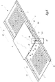
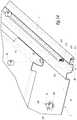
- the figure 13 illustrates another embodiment of the invention wherein the attachment means of an accessory on the sheet comprises, in addition to the head 213 of the fasteners 21, an intermediate member. In variant not shown, several intermediate members may be provided.
- This embodiment is illustrated by the fixing of rectangular plates 91 on assembled sheets 1, it being understood that it also concerns the fixing of square plates 90 or other accessories, provided that they do not have lugs 15 to 19. .
- the fixing of the plates 91 on the sheets 1 is effected by tabs 230 as illustrated in FIG. figure 15 .
- These tabs 230 are configured in L.
- a branch 231 of each tab 230 is supported on the body 6, at the level of the zones 70.
- This branch 231 is provided with a hole adapted to allow the insertion of the head 213 of one of the rods 21.
- the branch 231 is removably held on the plate 1 by the nut 22, similarly to the holding of an accessory 9 or a support member 8.
- the other branch 232 of the tab 230 extends opposite the sheet 1 relative to the branch 231, perpendicular to the body 6, upwardly looking at the figure 13 .
- This branch 232 is adapted to form a support for fixing a lip 110 of a plate 91.
- the lip 110 is fixed on the branch 232 by known means, for example by screws or rivets.
- the attachment may be final, for example by welding or gluing.
- the removal of the plate 91 involves the separation of the tab 230 of the sheet 1.
- the tab 230 is then an integral part of the accessory to be fixed.
- the plates 91 are assembled together, as in the embodiment illustrated in FIG. figure 10 but by interposing an intermediate member between the rod 21 and the accessory 91, namely the tab 230.
Landscapes
- Engineering & Computer Science (AREA)
- Architecture (AREA)
- Civil Engineering (AREA)
- Structural Engineering (AREA)
- Connection Of Plates (AREA)
- Finishing Walls (AREA)
Description
L'invention a trait à un dispositif de revêtement de paroi dans une structure, du type couramment utilisé dans le bâtiment sous le nom de système de bardage. Dans ce type de système une ou plusieurs faces extérieures du bâtiment sont revêtues par des plaques ou tôles de parement, dites tôles de bardage. Ces tôles sont fixées à des éléments qui font partie de la structure porteuse du bâtiment ou qui sont rapportés sur cette structure.The invention relates to a wall covering device in a structure, of the type commonly used in the building under the name of cladding system. In this type of system one or more outer faces of the building are coated with sheets or facing sheets, said cladding sheets. These sheets are attached to elements that are part of the load-bearing structure of the building or are reported on this structure.
Par structure, on désigne ici une ossature, par exemple réalisée par des profilés métalliques ou la paroi continue d'un mur par exemple en béton, en intérieur ou en extérieur, que cette paroi soit verticale, horizontale ou inclinée. Il s'agit, par exemple, d'un mur de séparation, d'un mur porteur ou d'un mur de maintien d'un talus. On désigne également par structure les éléments de charpente dans le toit d'un bâtiment, que ce dernier soit à usage domestique ou professionnel. Les tôles de bardage dans les dispositifs de revêtement connus de ce type sont formées de plaques ou tôles en matériau rigide, par exemple des tôles métalliques, fixées sur la structure. En variante, il peut s'agir de plaques non métalliques, par exemple en polymère, transparent ou non, ou en matériau composite que l'on qualifie également de « tôles » dans ce qui suit.By structure, here means a frame, for example made by metal profiles or the continuous wall of a wall for example concrete, inside or outside, that this wall is vertical, horizontal or inclined. This is, for example, a partition wall, a load-bearing wall or a wall holding a slope. Structural members are also referred to in the roof of a building, whether the latter is for domestic or professional use. The cladding sheets in the known coating devices of this type are formed of plates or sheets of rigid material, for example metal sheets, fixed to the structure. Alternatively, it may be non-metallic plates, for example polymer, transparent or not, or composite material which is also referred to as "sheets" in what follows.
Ces tôles sont généralement de forme rectangulaire et sont pourvues d'au moins deux nervures parallèles réparties sur deux bords parallèles de la tôle. Les nervures sont adaptées pour, soit recouvrir, soit être recouvertes par une nervure similaire d'une autre tôle, lorsque les tôles sont mises côte à côte ou aboutées. Le recouvrement partiel des tôles participe à l'étanchéité du revêtement de la structure.These sheets are generally rectangular in shape and are provided with at least two parallel ribs distributed over two parallel edges of the sheet. The ribs are adapted to either cover or be covered by a similar rib of another sheet, when the sheets are placed side by side or butted. The partial overlapping of the sheets contributes to the waterproofing of the structure's coating.
La fixation des tôles de bardage dans la structure s'effectue par des vis ou des rivets enfoncés dans des éléments constitutifs de la structure ou des éléments intermédiaires rapportés sur la structure, par exemple en métal ou en bois, pour aménager des intervalles dans l'épaisseur de la paroi revêtue, à des fins d'isolation, de circulation d'air ou de passage de composants fonctionnels, des câbles par exemple. C'est ainsi que dans une telle configuration, on peut ménager ou non un espace entre les tôles et la structure autorisant, par exemple, la mise en place d'un isolant et/ou le passage de conduites ou de câbles.The fastening of the cladding sheets in the structure is carried out by screws or rivets driven into elements constituting the structure or intermediate elements reported on the structure, for example metal or wood, to arrange intervals in the thickness of the coated wall, for purposes of insulation, air circulation or passage of functional components, cables for example. Thus, in such a configuration, it is possible or not a space between the sheets and the structure allowing, for example, the establishment of an insulator and / or the passage of pipes or cables.
Cette fixation doit autant que possible être étanche pour respecter les performances d'isolation requises par la réglementation. Elle s'effectue généralement par perçage de la tôle lors de son rivetage ou de son vissage dans la structure. Au besoin, un joint est prévu au niveau de chaque rivet ou de chaque vis pour assurer l'étanchéité.As far as possible, this fastening must be watertight to respect the insulation performance required by the regulations. It is generally performed by drilling the sheet during riveting or screwing into the structure. If necessary, a seal is provided at each rivet or screw for sealing.
A titre d'exemple illustrant ce qui précède,
- au moins une tôle, notamment une tôle de bardage, qui est adaptée pour revêtir au moins un secteur dans une face de cette structure, et qui présente une face interne, tournée vers ladite face de la structure, et une face externe, opposée à la face interne ;
- au moins un accessoire qui est adapté pour être rapporté sur une zone de réception, ménagée sur la face externe de la tôle, qui est configuré en forme de plaque ou cassette, carrée ou rectangulaire, et qui est adapté pour former, lorsqu'il est monté sur la tôle, un élément décoratif en soi ou bien un support de fixation pour d'autres éléments accessoires, décoratifs ou utilitaires;
- et des moyens de fixation adaptés pour fixer définitivement la tôle sur la structure.
- at least one sheet, in particular a cladding sheet, which is adapted to coat at least one sector in a face of this structure, and which has an internal face, facing said face of the structure, and an outer face, opposite to the internal face;
- at least one accessory which is adapted to be attached to a receiving area, formed on the outer face of the sheet, which is configured in the form of a plate or cassette, square or rectangular, and which is adapted to form, when it is mounted on the sheet, a decorative element in itself or a mounting bracket for other accessory items, decorative or utilitarian;
- and fastening means adapted to permanently fix the sheet on the structure.
Lesdits moyens de fixation comprennent des attaches qui sont adaptées pour être insérées à travers la tôle. Chacune des attaches est formée par une tige incluant en un seul organe :
- un secteur d'accrochage adapté pour être fixé définitivement dans la structure à travers la tôle;
- un élément d'appui, qui présente une face de serrage adaptée pour être appuyée sur la face externe de la tôle pour appliquer la face interne de la tôle contre la structure lorsque le secteur d'accrochage est fixé dans la structure à travers la tôle, de manière à fixer la tôle sur la structure de manière permanente et étanche;
- et une tête, qui est séparée du secteur d'accrochage par l'élément d'appui de manière à autoriser le montage et le démontage de l'accessoire sur la zone de réception alors que la tôle est déjà fixée sur la structure par le secteur d'accrochage, sans affecter, d'une part, l'intégrité structurelle de la tôle et, d'autre part, l'intégrité et l'étanchéité de la fixation de la tôle sur la structure par le secteur d'accrochage et l'élément d'appui.
- an attachment sector adapted to be fixed permanently in the structure through the sheet;
- a support element, which has a clamping face adapted to be supported on the outer face of the sheet to apply the internal face of the sheet against the structure when the attachment sector is fixed in the structure through the sheet, in order to fix the sheet on the structure permanently and tightly;
- and a head, which is separated from the hooking sector by the support member so as to allow mounting and dismounting of the accessory on the receiving area while the sheet is already attached to the structure by the sector. without affecting, on the one hand, the structural integrity of the sheet and, on the other hand, the integrity and tightness of the attachment of the sheet to the structure by the attachment sector and the support element.
Lesdits moyens de fixation comprennent également un moyen de maintien adapté pour maintenir un organe intermédiaire des moyens de fixation, fixé à l'accessoire, ce moyen de maintien coopérant de manière amovible avec la tête de la tige des attaches.Said fixing means also comprise a holding means adapted to hold an intermediate member of the fixing means, fixed to the accessory, the holding means cooperating removably with the head of the rod of the fasteners.
Par ailleurs, lors de la construction, il est possible de prévoir certaines variations dans la fonction et /ou l'aspect des revêtements ainsi réalisés. On peut par exemple alterner des zones ou secteurs de tôles de couleurs différentes ou intercaler des zones transparentes pour laisser pénétrer la lumière à l'intérieur. On peut aussi, dans une certaine mesure et moyennant le recours à des pièces de raccord ou profilés de transition, alterner des zones dans lesquelles les dimensions en largeur (entre nervures) ou en longueur sont différentes. Cependant, une fois le revêtement en place, il y reste pour des périodes qui peuvent être longues, souvent de plusieurs dizaines d'années, sans qu'aucun changement substantiel dans son aspect ou ses fonctions puisse y être apporté sous peine d'en altérer l'intégrité structurelle et les qualités de protection, notamment son étanchéité ou sa résistance aux intempéries.Moreover, during construction, it is possible to provide certain variations in the function and / or appearance of the coatings thus produced. For example, zones or sectors of different colored plates can be alternated or transparent zones can be inserted to allow the light to penetrate inside. It is also possible, to a certain extent and using the use of connecting pieces or transition profiles, alternating areas in which the dimensions in width (between ribs) or in length are different. However, once the coating is in place, it remains there for periods that can be long, often of several decades, without any substantial change in its appearance or functions can be brought under penalty of altering structural integrity and protective qualities, including tightness or weather resistance.
Il arrive donc que si les utilisateurs souhaitent apposer sur les faces du bâtiment des enseignes ou des plaques de signalisation, voire des panneaux publicitaires, ils soient contraints de réaliser de nouveaux perçages dans la ou les tôles de bardage pour réaliser les accrochages nécessaires. Il en va de même pour l'ajout d'éléments fonctionnels, tels que des points d'éclairage, supports de câbles ou autres organes. Ces perçages contribuent à dégrader l'intégrité des tôles dans lesquelles ils sont pratiqués et affectent leur longévité et leur aspect dans la durée. Ce défaut est encore aggravé lorsqu'il faut démonter des éléments ajoutés pour les remplacer par d'autres qui nécessitent de nouveaux perçages.It therefore happens that if users wish to affix on the sides of the building signs or signs or advertising signs, they are forced to make new holes in the cladding sheet or sheets to achieve the necessary clashes. The same goes for adding elements functional, such as lighting points, cable supports or other organs. These holes contribute to degrade the integrity of the sheets in which they are practiced and affect their longevity and appearance over time. This defect is further aggravated when it is necessary to dismantle added elements to replace them by others that require new holes.
Ainsi les systèmes existants souffrent d'une double limitation ou défaut. D'une part ils ne permettent pas de réaliser aisément des revêtements avec des variations d'aspect ou des motifs multiples dans chaque face recouverte, indépendamment des contraintes imposées par la configuration peu diversifiée des tôles disponibles et par les besoins liés à leur recouvrement en bordure. D'autre part, ils supportent mal l'addition d'éléments amovibles susceptibles d'être modifiés ou déplacés une ou plusieurs fois pendant la vie de la construction revêtue.Thus existing systems suffer from a double limitation or defect. On the one hand, they do not make it possible to easily produce coatings with variations of appearance or multiple patterns in each coated face, independently of the constraints imposed by the undiversified configuration of the available sheets and by the needs related to their capping at the edges. . On the other hand, they do not support the addition of removable elements that can be modified or moved one or more times during the life of the coated construction.
Pour contourner cette problématique, le document d'art antérieur
Le but de la présente invention est de proposer une solution alternative, qui, tout en étant économique et performante mécaniquement, permet de varier l'aspect visuel ou les propriétés fonctionnelles d'une tôle de revêtement d'une structure, le cas échéant après la pose, en fonction de l'évolution des besoins esthétiques ou fonctionnels, sans remettre en cause l'intégrité physique et les qualité propres de la fixation de la tôle sur la structure.The object of the present invention is to propose an alternative solution, which, while being economical and mechanically efficient, makes it possible to vary the visual appearance or the functional properties of a coating sheet of a structure, where appropriate after the poses, according to the evolution of the aesthetic or functional needs, without calling into question the physical integrity and the own quality of the fixing of the sheet on the structure.
A cet effet, l'invention a pour objet un dispositif de revêtement tel que défini à la revendication 1.For this purpose, the subject of the invention is a coating device as defined in
Ainsi, une des idées à la base de l'invention est de tirer profit des attaches de fixation préalable de la tôle sur la structure de sorte qu'une tête de ces attaches forme, au moins en partie, des moyens de fixation d'un ou plusieurs accessoires, propres à n'affecter ni la qualité ou l'intégrité, notamment fonctionnelle, de la fixation entre la tôle et la structure ni la tôle elle-même. Cela permet de modifier l'aspect et/ou certaines fonctionnalités du revêtement d'un bâtiment, de lui conférer une modularité ou de réaliser des motifs dans des panneaux revêtus selon ce système. On comprend que ces moyens de fixation de l'accessoire sur la tôle puissent être adaptés pour réaliser une fixation amovible de l'accessoire qui peut donc être démonté ou remonté sans attenter à la solidité ou l'intégrité de la construction de base.Thus, one of the ideas underlying the invention is to take advantage of the prior fasteners of the sheet metal on the structure so that a head of these fasteners forms, at least in part, means for fixing a or several accessories, suitable to affect neither the quality or the integrity, especially functional, of the binding between the sheet and the structure nor the sheet itself. This makes it possible to modify the appearance and / or certain functionalities of the coating of a building, to give it a modularity or to create patterns in panels coated according to this system. It is understood that these fastening means of the accessory on the sheet can be adapted to achieve a removable attachment of the accessory which can be disassembled or reassembled without compromising the strength or integrity of the basic construction.
Grâce à la disposition appropriée d'accessoires rapportés sur les tôles, le système permet de respecter les formes ou les propriétés d'un design préétabli, spécifique de chaque projet, à partir d'éléments de base qui peuvent être les mêmes. Il permet également après la réalisation de la construction et sa mise en service d'ajouter des accessoires et de les enlever, ou de les adapter aux évolutions de l'usage et aux besoins divers qui peuvent se présenter, par exemple en matière de signalisation ou d'affichage ou de fonctionnalités diverses. Le changement du ou des accessoires sur la tôle, l'adjonction de tels éléments peuvent s'effectuer en évitant tout perçage ou intervention intrusive dans la tôle déjà en place ou dans sa structure et les moyens d'assemblage par lesquels ils sont associés au montage initial. La modification de l'aspect de la structure en est facilitée, l'intégrité, notamment l'étanchéité, de la fixation de la tôle sur la structure est dans tous les cas préservée.Thanks to the appropriate arrangement of accessories reported on the sheets, the system makes it possible to respect the shapes or properties of a predetermined design, specific to each project, based on basic elements that may be the same. It also allows after the completion of the construction and its commissioning to add accessories and remove them, or to adapt to changes in use and various needs that may arise, for example in terms of signage or display or various features. The change of the accessory or accessories on the sheet, the addition of such elements can be done by avoiding any drilling or intrusive intervention in the sheet already in place or in its structure and the assembly means by which they are associated with mounting initial. The modification of the appearance of the structure is facilitated, the integrity, including sealing, of the attachment of the sheet to the structure is in any case preserved.
Des aspects avantageux mais non obligatoires du dispositif de recouvrement selon l'invention sont spécifiés aux revendications dépendantes.Advantageous but non-mandatory aspects of the recovery device according to the invention are specified in the dependent claims.
L'invention s'étend aussi à une structure de bâtiment telle que définie à la revendication 14.The invention also extends to a building structure as defined in
L'invention sera mieux comprise et d'autres avantages de celle-ci apparaîtront plus clairement à la lecture de la description qui va suivre d'un dispositif de recouvrement réalisé conformément à plusieurs modes de réalisation de l'invention, donnée uniquement à titre d'exemple et faite en se référant aux dessins annexés dans lesquels :
- la
figure 1 est une vue en perspective d'une tôle nervurée selon un mode de réalisation conforme à l'invention, - la
figure 2 est une vue en perspective, à une autre échelle, d'un accessoire décoratif perpendiculaire aux nervures sur la tôle de lafigure 1 , - la
figure 3 est une vue en perspective, à une autre échelle, d'un autre type d'accessoire utilisable avec la tôle de lafigure 1 , - la
figure 4 est une vue en perspective, à la même échelle que lafigure 1 , illustrant le montage amovible d'organes décoratifs de lafigure 2 sur la tôle de lafigure 1 , - la
figure 5 est une vue en perspective, à la même échelle, illustrant la mise en place de l'accessoire de lafigure 3 sur la tôle de lafigure 1 , - la
figure 6 est une vue partielle en perspective, similaire à lafigure 5 et à la même échelle, lorsque l'accessoire est fixé sur la zone de réception de la tôle, - la
figure 7 est une vue de bout, selon la flèche VII à lafigure 6 , - la
figure 8 est une vue de côté, selon la flèche VIII à lafigure 6 , - la
figure 9 est une vue en perspective, à plus petite échelle, de plusieurs tôles de lafigure 5 disposées côte à côte, en recouvrement partiel, les accessoires de lafigure 3 étant fixés sur certaines zones de réception des tôles, - la
figure 10 est une vue en perspective, similaire à lafigure 9 et à la même échelle, les tôles de lafigure 1 étant équipées d'organes de support illustrés à lafigure 2 , - la
figure 11 est une vue en perspective, à la même échelle que lafigure 3 , d'un autre type d'accessoire formant également un support et conforme à un autre mode de réalisation de l'invention, - la
figure 12 est une vue en perspective, à une autre échelle, similaire à lafigure 9 , des accessoires formant support, fixés sur des tôles assemblées, recevant d'autres accessoires dont un est illustré en position de pré montage, - la
figure 13 est une vue en perspective, similaire à lafigure 9 et à la même échelle, un autre type d'accessoire étant illustré monté et en position de pré montage sur des accessoires formant des organes de support conformes à un autre mode de réalisation de l'invention, - la
figure 14 est une vue partielle en perspective, à plus grande échelle, du détail XIV à lafigure 5 et illustrant la mise en place de l'accessoire sur la tôle, des boulons étant représentés en position de prémontage, - la
figure 15 est une vue à plus grande échelle du détail XV à lafigure 13 , et - la
figure 16 est une vue en perspective d'une variante de la tôle de lafigure 1 .
- the
figure 1 is a perspective view of a ribbed sheet metal according to an embodiment according to the invention, - the
figure 2 is a perspective view, on a different scale, of a decorative accessory perpendicular to the ribs on the sheet metal of thefigure 1 , - the
figure 3 is a perspective view, on another scale, of another type of accessory usable with the sheet metal of thefigure 1 , - the
figure 4 is a perspective view, on the same scale as thefigure 1 , illustrating the removable assembly of decorative organs of thefigure 2 on the sheet of thefigure 1 , - the
figure 5 is a perspective view, on the same scale, illustrating the setting up of the accessory of thefigure 3 on the sheet of thefigure 1 , - the
figure 6 is a partial perspective view, similar to thefigure 5 and at the same scale, when the accessory is attached to the receiving area of the sheet, - the
figure 7 is an end view, according to the arrow VII at thefigure 6 , - the
figure 8 is a side view, according to arrow VIII at thefigure 6 , - the
figure 9 is a perspective view, on a smaller scale, of several sheets offigure 5 arranged side by side, in partial overlap, the accessories of thefigure 3 being fixed on certain zones of reception of the sheets, - the
figure 10 is a perspective view, similar to thefigure 9 and on the same scale, the sheets of thefigure 1 being equipped with support devices illustrated infigure 2 , - the
figure 11 is a perspective view, on the same scale as thefigure 3 another type of accessory also forming a support and according to another embodiment of the invention, - the
figure 12 is a perspective view, on a different scale, similar to thefigure 9 , accessories forming a support, fixed on assembled plates, receiving other accessories, one of which is illustrated in pre-assembly position, - the
figure 13 is a perspective view, similar to thefigure 9 and on the same scale, another type of accessory being illustrated mounted and in pre-assembly position on accessories forming support members according to another embodiment of the invention, - the
figure 14 is a partial perspective view, on a larger scale, from detail XIV tofigure 5 and illustrating the placing of the accessory on the sheet, bolts being shown in pre-assembly position, - the
figure 15 is a larger-scale view of detail XV at thefigure 13 , and - the
figure 16 is a perspective view of a variant of the sheet metal of thefigure 1 .
La
Les nervures 4, 5 de la tôle 1 sont ici constitutives des bords 2, 3. En variante, elles sont disposées selon la largeur de la tôle. Dans une autre variante, les nervures 4,5 ne définissent pas les bords de la tôle mais occupent la partie centrale de cette dernière. Dans d'autres modes de réalisation, la tôle peut être de forme carrée.The
A la
Un accessoire 8, illustré à la
Le barreau 8 a une longueur adaptée à la largeur du corps 6 pour être monté sur le corps 6 perpendiculairement aux nervures 4 et 5 tout en étant en contact, par ses extrémités, avec les flancs des nervures 4 et 5, comme cela est visible à la
Un autre type d'accessoire 9 est représenté à la
La plaque 9 a ses quatre cotés pliés, par exemple ici à angle droit, par rapport à sa face 10, formant ainsi quatre lèvres 11 à 14 angulées par rapport à la face supérieure 10 de la plaque 9. Les lèvres 11 à 14 sont orientées vers la tôle 1 lorsque la plaque 9 est en position sur cette dernière.The
Des pattes allongées 15 à 19 s'étendent à partir des extrémités libres des lèvres 11 à 14 comme cela ressort de la
Les pattes 15 à 19 sont disposées différemment sur chaque lèvre. Sur la lèvre 11, la patte 15 est fixée sur une extrémité de la lèvre qui est voisine d'une extrémité de la lèvre 12. Les lèvres 12 et 13 sont équipées, en position centrale, des pattes 16, respectivement 17. Deux pattes 18 et 19 sont, quant à elles, situées au voisinage des extrémités de la lèvre 14.The
Une telle disposition des pattes 15 à 19 permet, lorsqu'une plaque 9 est positionnée à côté d'une autre plaque 9 identique, d'amener en regard deux lèvres des plaques dont les pattes 15 à 19 respectives sont décalées l'une par rapport à l'autre, afin de minimiser l'espace entre les plaques voisines sans que ces dernières soient pour autant jointives. En d'autres termes, il n'y a pas de chevauchement des pattes 15 à 19 de deux plaques 9 voisines.Such an arrangement of the
Dans d'autres modes de réalisation non illustrés, la disposition des pattes est différente, pour autant que cette disposition permette d'éviter un chevauchement tout en e minimisant l'espace entre deux plaques voisines.In other embodiments not shown, the arrangement of the tabs is different, provided that this arrangement avoids overlap while minimizing the space between two adjacent plates.
A la
Des attaches de fixation, de manière permanente et étanche, de la tôle 1 sur une face d'une structure, non illustrée pour plus de lisibilité, sont formés par des tiges filetées 21. Ces tiges 21 sont insérées dans des orifices traversant la tôle 1. Les orifices sont soit réalisés en usine soit, préférentiellement, sur site. Dans ce cas, les tiges sont avantageusement pourvues d'une pointe auto perforante.Permanently and tightly fastening fasteners for the
Certaines tiges 21 sont insérées au niveau des parties R3 des nervures 4 et 5, d'autres dans le corps 6, soit entre deux groupes G1 à G3 de reliefs 7, soit entre deux reliefs 7 d'un même groupe G1 à G3. Le nombre et la répartition des moyens de fixation 21 des tôles sur la structure dépendent des critères du recouvrement entre les tôles 1, des dimensions des tôles 1 et des conditions de montage, par exemple de la résistance au vent imposée par la réglementation ou du poids des accessoires devant être supportés par la tôle 1. L'étanchéité de la fixation de la tôle 1 sur la structure est réalisée, par exemple, par un joint d'étanchéité. Afin de faciliter et d'optimiser la fixation de la tôle 1 sur la structure, la répartition des tiges 21 sur la tôle 1 est repérée par un pictogramme, une prédécoupe, un marquage en relief, à l'aide de gabarits fournis avec la tôle ou par tout autre moyen de repérage connu. Les tiges 21 sont des fixations à double fonction.Some
Les tiges 21 comprennent une partie adaptée pour maintenir, de manière étanche, une tôle 1 sur une structure. Cette partie comprend, comme cela apparait plus clairement à la
La tête 213 forme un moyen de fixation d'un accessoire sur la tôle 1.The
A la
Comme cela apparait notamment à la
On a ainsi réalisé une attache, sous la forme de la tige 21, pour la fixation d'un accessoire amovible, tel que l'accessoire 8 ou 9, dans un dispositif de revêtement tel que décrit ci-dessus. Cette attache peut être décrite comme:
- comprenant un corps d'attache, ou tige, comprenant une premier secteur d'accrochage, tel que la
portion filetée 210, propre à se fixer dans la structure, un élément de serrage, tel que la collerette 212, coopérant avec ce premier secteur d'accrochage et comportant une face de serrage pour appliquer une face interne de la tôle 70 contre la structure lorsque le premier secteur est fixé dans celle ci, et un deuxième secteur d'accrochage, tel que la tête 213, pour la réception d'un accessoire, tel que l'accessoire 8ou 9, en particulier la patte 15 de ce dernier, rapporté du côté de la face externe de la tôle 70, et - étant associée à un moyen de serrage, tel que l'écrou 22, coopérant de façon amovible avec le deuxième secteur d'accrochage pour appliquer l'accessoire contre une butée solidaire de l'élément de serrage.
- comprising a fastening body, or rod, comprising a first attachment sector, such as the threaded
portion 210, adapted to be fixed in the structure, a clamping element, such as theflange 212, cooperating with this first sector and having a clamping face for applying an internal face of thesheet 70 against the structure when the first sector is fixed therein, and a second hooking sector, such as thehead 213, for receiving a accessory, such as theaccessory tab 15 of the latter, attached to the side of the external face of thesheet 70, and - being associated with a clamping means, such as the
nut 22, cooperating removably with the second attachment sector to apply the accessory against an abutment integral with the clamping element.
Les accessoires 8 sont ainsi fixés sur la tôle 1 sans altérer l'étanchéité de la fixation de la tôle 1 sur la structure et sans modifier l'intégrité structurelle de la tôle 1, par exemple par perçage. Dans le mode de réalisation illustré à la
La
Ainsi, dans ce mode de réalisation, la zone de réception Z de l'accessoire est délimitée entre, d'une part, les nervures 4, 5 et, d'autre part, deux zones planes 70 situées de part et d'autre d'un groupe G2 de reliefs 7.Thus, in this embodiment, the receiving zone Z of the accessory is delimited between, on the one hand, the
La
Les dimensions de la plaque 9, des nervures 4 et 5 et de la tôle 1 font que la surépaisseur due à la mise en place de la plaque 9 est minimale, comme cela ressort des
L'aspect visuel de la tôle 1 est modifié, seule la face 10 de la plaque 9 étant visible. On comprend que plusieurs plaques 9 peuvent, au choix, être montées sur la tôle 1. Le comportement mécanique et la résistance de la tôle 1 ne sont pas ou peu affectés par le montage de la ou des plaques 9 dans la mesure où aucun perçage ou découpe ne doit être réalisé dans la tôle 1.The visual appearance of the
La
En fonction des besoins, on choisit le pourcentage de couverture des tôles 1 par les plaques 9 ainsi que la répartition de ces dernières sur les tôles 1. On note que les faces 10 des plaques 9 sont coplanaires mais non jointives. Un jour J, dont la largeur correspond sensiblement à la largeur des pattes 15 à 19, est ménagé entre deux plaques 9 adjacentes.Depending on the needs, the percentage of coverage of the
La disposition des pattes 15 à 19 sur les lèvres 11 à 14 permet, lorsque deux plaques 9 sont côte à côte, que leurs pattes 15 à 19 respectives s'intercalent et ne se chevauchent pas. On ménage ainsi une zone de juxtaposition entre deux plaques 9 rectiligne et homogène, sans surépaisseur, les pattes 15 à 19 des deux plaques s'intercalant pour être dans le prolongement les unes des autres selon une direction parallèle aux faces 10 de ces plaques.The arrangement of the
La
Ainsi, chaque plaque 90 ou 91 est fixée sur les barreaux 8 eux-mêmes fixés sur le corps 6, comme illustré à la
La fixation des plaques 90, 91 se fait, par exemple, par vissage sur les accessoires 8. En variante, la fixation est réalisée par un système de clips ou, dans le cas d'une fixation définitive, par collage ou soudage. Dans une telle configuration, c'est l'ensemble accessoire 8 et plaques 90 ou 91 qui est amovible, pas une plaque 90, 91 seule.The fixing of the
Chaque plaque 9, 90, 91 est avantageusement montée, de manière amovible, tant au niveau des nervures 4, 5 que des accessoires 8.Each
Grâce à l'invention, il est possible de changer d'accessoire autant que de besoin, celui-ci pouvant être une plaque 9, 90, 91 colorée, porteuse d'un graphisme, de reliefs décoratifs ou d'une impression.Thanks to the invention, it is possible to change the accessory as necessary, it can be a
En variante, cet accessoire peut être une platine d'un projecteur, une platine de fixation d'une enceinte de type haut parleur, une platine de fixation d'un pot de fleurs ou d'une jardinière, une platine de fixation d'une lettre en relief ou d'autres accessoires pour autant que cet accessoire, ou au moins la partie de l'accessoire destinée à être fixée sur la tôle, a une forme compatible avec la configuration géométrique de la tôle 1 et, avantageusement, est pourvu d'orifices 20, ces derniers étant préférentiellement percés en usine.As a variant, this accessory may be a stage of a projector, a mounting plate for a loudspeaker type speaker, a mounting plate for a flowerpot or a planter, a mounting plate for a embossed letter or other accessories provided that this accessory, or at least the part of the accessory intended to be fixed on the sheet, has a shape compatible with the geometric configuration of the
Dans un mode de réalisation représenté aux
En particulier, la plaque 92 comprend un lamage central 94 ménagé parallèlement à deux côtés parallèles 95, 96 de la plaque 92. De part et d'autre de ce lamage central 94, s'étendent d'autres lamages, soit perpendiculaires aux lamages 94, comme les lamages 97, soit inclinés comme les lamages 98, 99. L'ensemble des lamages 94, 97, 98, 99 a ainsi une configuration en arbre ou en étoile. Des perçages 100 sont ménagés dans le lamage central 94. En variante, d'autres perçages sont ménagés sur les autres lamages 97, 98, 99. Chaque lamage est adapté, par sa forme et/ou ses dimensions pour recevoir un autre accessoire à fixer, de manière amovible, sur la cassette 92.In particular, the
Une telle cassette 92 est destinée, une fois en place sur la tôle, à former un support de fixation, amovible, pour d'autres accessoires, tout en étant elle-même amovible, cela sans altérer l'étanchéité de la fixation entre la tôle 1 et la structure ni compromettre l'intégrité physique et la résistance mécanique de la tôle 1.Such a
La
Ainsi, dans tous les modes de réalisation décrits précédemment, de manière avantageuse et afin de limiter la création de perçages dans la tôle 1, l'attache de fixation définitive de la tôle 1 sur la structure et le moyen de fixation amovible de l'accessoire sur la tôle sont portés par un seul et même organe, la tige 21, dont la tête 213 est pourvue d'un moyen de fixation amovible de l'accessoire. Il s'agit, par exemple comme illustré aux différentes figures, d'un filetage.Thus, in all the embodiments described above, advantageously and in order to limit the creation of holes in the
En variante non illustrée, la tête de la tige 21 est pourvue d'un taraudage, d'un dispositif de clipsage, d'un dispositif à baïonnettes, de bandes auto agrippantes ou autres dispositifs permettant le montage d'un accessoire sur la tête de la tige, étant entendu que l'écrou 22 est adapté à la configuration de la tête.In a variant not shown, the head of the
La
Ce mode de réalisation est illustré par la fixation de plaques rectangulaires 91 sur des tôles 1 assemblées, étant entendu qu'il concerne également la fixation de plaques carrées 90 ou d'autres accessoires, pour autant que ces derniers sont dépourvus de pattes 15 à 19.This embodiment is illustrated by the fixing of
La fixation des plaques 91 sur les tôles 1 est effectuée par des pattes 230 telles qu'illustrées à la
L'autre branche 232 de la patte 230 s'étend à l'opposé de la tôle 1 par rapport à la branche 231, perpendiculairement au corps 6, vers le haut en regardant la
En variante, la fixation peut être définitive, par exemple par soudage ou collage. Dans ce cas, le retrait de la plaque 91 implique la séparation de la patte 230 de la tôle 1. En d'autres termes, la patte 230 est alors partie intégrante de l'accessoire à fixer.Alternatively, the attachment may be final, for example by welding or gluing. In this case, the removal of the
Dans le mode de réalisation de la
Claims (14)
- Device for covering at least one structure in a building or analogous construction, comprising:- at least one sheet (1; 1'), especially a cladding sheet, which is adapted to cover at least one section in a face of the structure and which has an inside face, facing said face of the structure, and an outside face, opposite the inside face,- at least one accessory (9; 90; 91; 92) which is adapted to be fitted to a receiving zone (Z, Z1) formed on the outside face of the sheet, which is configured in the form of a plate or cassette, square (9; 90; 92) or rectangular (91), and which is adapted to form, when it is mounted on the sheet (1; 1'), a decorative element in itself or a fixing support for other decorative or utilitarian accessory elements, and- fixing means (21, 22; 21, 22, 8; 21, 22, 230) adapted to fix the sheet (1; 1') permanently to the structure and to fix the accessory (9; 90; 91; 92) removably to the receiving zone (Z, Z1), which fixing means comprise:(i) fasteners (21) which are adapted to be inserted through the sheet, each of the fasteners being formed by a rod including in a single member:- an attachment section (210) adapted to be fixed permanently in the structure through the sheet,- a supporting element (212) which has a clamping face adapted to be pressed against the outside face of the sheet in order to apply the inside face of the sheet against the structure when the attachment section is fixed in the structure through the sheet, so as to fix the sheet to the structure permanently and tightly, and- a head (213) which is separated from the attachment section by the supporting element and which is adapted to be removably fixed to the accessory (9; 90; 91; 92) so as to allow the accessory to be mounted on and dismounted from the receiving zone when the sheet is already fixed to the structure by the attachment section, without affecting on the one hand the structural integrity of the sheet and on the other hand the integrity and tightness of the fixing of the sheet to the structure by the attachment section and the supporting element, and(ii) a holding means (22) adapted to hold, on the rod of the fasteners (21), the accessory (9; 90; 91; 92) or an intermediate member (8; 230) of the fixing means, fixed to the accessory (9; 90; 91; 92), the holding means (22) cooperating in a removable manner with the head (213) of the rod of the fasteners (21) in order to clamp the accessory (9; 90; 91; 92) or the intermediate member (8; 230), in the direction of the sheet (1; 1'), against the supporting element (212) of the rod of the fasteners (21).
- Device according to claim 1, characterised in that the receiving zone (Z, Z1) and the fixing means (21, 22; 21, 22, 8; 21, 22, 230) are arranged to allow a plurality of accessories (9; 90; 91; 92) to be mounted in the face of the covered structure, in accordance with a predetermined visual pattern.
- Device according to any one of the preceding claims, characterised in that the sheet (1; 1') comprises at least one longitudinal rib (4, 5; 4', 5') and said at least one receiving zone includes at least one receiving zone (Z, Z1) parallel to the rib.
- Device according to claim 1 or 2, characterised in that the sheet (1; 1') comprises at least two parallel longitudinal ribs (4, 5; 4', 5') and said at least one receiving zone (Z1) includes at least one transverse receiving zone between the two ribs of the sheet.
- Device according to claim 4, characterised by a plurality of transverse receiving zones (Z; Z1) each capable of receiving an accessory extended transversely between the ribs.
- Device according to any one of the preceding claims, characterised in that the attachment section (210) of the rod of the fasteners (21) is threaded.
- Device according to any one of the preceding claims, characterised in that the supporting element (212) of the rod of the fasteners (21) forms a collar (212).
- Device according to claims 7 and 8, characterised in that the rod of the fasteners (21) is provided with a seal, which is provided beneath the collar (212) and around the attachment section (210).
- Device according to any one of the preceding claims, characterised in that the head (213) of the rod of the fasteners (21) is threaded and the holding means is a nut (22) screwed onto the head.
- Device according to claim 9, characterised in that the nut (22) is blind and forms a protective cap for the head (213) of the rod of the fasteners (21).
- Device according to either claim 9 or claim 10, characterised in that the nut (22) is provided with manoeuvring notches or grooves (220) for screwing the nut onto the head (213) of the rod of the fasteners (21).
- Device according to any one of the preceding claims, characterised in that the head (213) of the rod of the fasteners (21) has a means (214) for manoeuvring the rod in order to fix the attachment section (21) in the structure upon mounting of the sheet (1; 1') on the structure.
- Device according to any one of the preceding claims, characterised in that the intermediate member is a bent lug (230) or a bar (8) capable of supporting the accessory (9; 90; 91; 92).
- Building structure covered with a device according to any one of the preceding claims, characterised by a plurality of accessories (9; 90; 91; 92) mounted in the receiving zone or a plurality of the receiving zones (Z, Z1) of the device to form (a) visual pattern(s) chosen or determined as a function of a pre-established design.
Applications Claiming Priority (2)
| Application Number | Priority Date | Filing Date | Title |
|---|---|---|---|
| FR1253947A FR2989982A1 (en) | 2012-04-27 | 2012-04-27 | DEVICE FOR COATING A BUILDING STRUCTURE AND STRUCTURE COATED BY SUCH A DEVICE |
| PCT/EP2013/058767 WO2013160457A1 (en) | 2012-04-27 | 2013-04-26 | Device for covering a building structure and structure covered by such a device |
Publications (2)
| Publication Number | Publication Date |
|---|---|
| EP2841663A1 EP2841663A1 (en) | 2015-03-04 |
| EP2841663B1 true EP2841663B1 (en) | 2019-04-10 |
Family
ID=48407449
Family Applications (1)
| Application Number | Title | Priority Date | Filing Date |
|---|---|---|---|
| EP13721619.8A Active EP2841663B1 (en) | 2012-04-27 | 2013-04-26 | Device for covering a building structure and structure covered by such a device |
Country Status (5)
| Country | Link |
|---|---|
| US (1) | US9523205B2 (en) |
| EP (1) | EP2841663B1 (en) |
| FR (1) | FR2989982A1 (en) |
| RU (1) | RU2625662C2 (en) |
| WO (1) | WO2013160457A1 (en) |
Families Citing this family (9)
| Publication number | Priority date | Publication date | Assignee | Title |
|---|---|---|---|---|
| US20150191914A1 (en) * | 2014-01-07 | 2015-07-09 | Eran Biterman | Method and system for covering surfaces with decorative panels |
| KR102074769B1 (en) * | 2018-02-22 | 2020-02-07 | 삼원액트 주식회사 | The metal interior material and interior material attachment structure |
| US11505948B2 (en) * | 2018-11-08 | 2022-11-22 | mfPHD, LLC | Wall system |
| US11098477B2 (en) | 2018-11-08 | 2021-08-24 | mfPHD, LLC | Monolithic corner |
| WO2022103553A2 (en) * | 2020-11-14 | 2022-05-19 | mfPHD, LLC | Backplate arrangements and gap cover apparatus for modular wall systems and installation methods |
| US10995498B1 (en) * | 2021-01-14 | 2021-05-04 | Harvey Fein | Polygon tile for tessellating and method of making the same |
| JP6906829B1 (en) * | 2021-02-12 | 2021-07-21 | タケシンパッケージ株式会社 | How to install the design material set and the design material set |
| US11873644B2 (en) | 2021-09-01 | 2024-01-16 | mfPHD, LLC | Modular wall units having front panels with aesthetic designs covering a window for modular wall systems |
| IT202300025680A1 (en) * | 2023-12-01 | 2025-06-01 | Elena Zanella | ORNAMENTAL WALL |
Citations (1)
| Publication number | Priority date | Publication date | Assignee | Title |
|---|---|---|---|---|
| EP0481905A1 (en) * | 1990-10-18 | 1992-04-22 | Gantan Beauty Industry Co., Ltd. | Double roofing roof structure |
Family Cites Families (17)
| Publication number | Priority date | Publication date | Assignee | Title |
|---|---|---|---|---|
| GB1387272A (en) * | 1971-10-08 | 1975-03-12 | Cookson Sheet Metal Dev Ltd | Sheet fixing devices |
| US3906696A (en) * | 1973-10-18 | 1975-09-23 | Armco Gmbh | Profiled panel for the cladding of walls, ceilings, roofs and the like |
| DE2523292B2 (en) * | 1975-05-26 | 1978-06-01 | Siemens Ag, 1000 Berlin Und 8000 Muenchen | Housing for electrotechnical devices |
| US4486998A (en) * | 1982-05-07 | 1984-12-11 | H. H. Robertson Company | Concealed fastener roof or wall structure and method of assembly |
| US4467582A (en) * | 1982-09-29 | 1984-08-28 | H. H. Robertson Company | Joint retention clip for rib-like panel joint |
| US5207045A (en) * | 1991-06-03 | 1993-05-04 | Bodnar Ernest R | Sheet metal structural member, construction panel and method of construction |
| FR2680816A1 (en) * | 1991-08-27 | 1993-03-05 | Axter | WATERPROOF COVERING OF A BUILDING AND ITS APPLICATION METHOD. |
| FI95957C (en) * | 1994-05-19 | 1996-04-10 | Polar Rakennus Oy | Skeletal system based method for mounting elements and its use |
| US6443418B1 (en) * | 2000-10-26 | 2002-09-03 | Kozo Itamochi | Ultra thin-type form panel, a form employing the same, and a method for constructing a foundation |
| GB0028930D0 (en) * | 2000-11-28 | 2001-01-10 | Gleave David S | Roof safety system |
| DE10106752A1 (en) * | 2001-02-14 | 2002-08-29 | Km Europa Metal Ag | cladding |
| US6974622B2 (en) * | 2002-01-16 | 2005-12-13 | Paragon Plastic Sheet, Inc. | Plastic sheets for use in protecting openings in walled structures |
| GB2421254B (en) * | 2004-12-14 | 2010-03-03 | Kingspan Res & Dev Ltd | A composite cladding |
| US20070113494A1 (en) * | 2005-11-03 | 2007-05-24 | Guardian Industries Corp. | Storm shutter system |
| US7954282B2 (en) * | 2008-04-07 | 2011-06-07 | Guardian Building Products, Inc. | Storm shutter assembly clip, and/or storm shutter system and/or assembly method including the same |
| KR20100131499A (en) * | 2008-04-11 | 2010-12-15 | 큐엘디 스틸 피티와이 엘티디 | Structural building material and assembly method thereof |
| US9010054B2 (en) * | 2011-06-15 | 2015-04-21 | Biosips, Inc. | Structural insulated building panel |
-
2012
- 2012-04-27 FR FR1253947A patent/FR2989982A1/en not_active Withdrawn
-
2013
- 2013-04-26 US US14/397,473 patent/US9523205B2/en not_active Expired - Fee Related
- 2013-04-26 WO PCT/EP2013/058767 patent/WO2013160457A1/en not_active Ceased
- 2013-04-26 EP EP13721619.8A patent/EP2841663B1/en active Active
- 2013-04-26 RU RU2014147738A patent/RU2625662C2/en not_active IP Right Cessation
Patent Citations (1)
| Publication number | Priority date | Publication date | Assignee | Title |
|---|---|---|---|---|
| EP0481905A1 (en) * | 1990-10-18 | 1992-04-22 | Gantan Beauty Industry Co., Ltd. | Double roofing roof structure |
Also Published As
| Publication number | Publication date |
|---|---|
| EP2841663A1 (en) | 2015-03-04 |
| WO2013160457A1 (en) | 2013-10-31 |
| RU2014147738A (en) | 2016-06-20 |
| FR2989982A1 (en) | 2013-11-01 |
| US9523205B2 (en) | 2016-12-20 |
| US20150322679A1 (en) | 2015-11-12 |
| RU2625662C2 (en) | 2017-07-18 |
Similar Documents
| Publication | Publication Date | Title |
|---|---|---|
| EP2841663B1 (en) | Device for covering a building structure and structure covered by such a device | |
| EP1841929B1 (en) | Arrangement of elements for producing a panel | |
| EP2924193A1 (en) | Fence, kit and method for installing said fence | |
| CA2194871A1 (en) | Adjustable staircase | |
| EP0186217A1 (en) | Frame | |
| EP0940515A1 (en) | Modular element for constructing a ceiling and a ceiling composed of such modular elements | |
| FR2458640A1 (en) | Metal false ceiling for building - has light alloy supports allowing variable fixing of ceiling panels | |
| BE1003554A3 (en) | Screen e.g. for projecting pictures - consists of frame assembled from rigid extrusions and fabric layer with edge fixing which attach to frame | |
| CA2040524C (en) | Modular finishing panel, particularly for suspended ceilings | |
| EP2841664B1 (en) | System for covering a metal sheet | |
| CA2538158C (en) | Presentation case | |
| FR3004067A1 (en) | PROFILE, IN PARTICULAR METALLIC, FOR ALLOWING A FIXATION OF A FILM ON A GREENHOUSE STRUCTURE AND A SYSTEM FOR FIXING A FILM ON A GREENHOUSE STRUCTURE COMPRISING SUCH A PROFILE | |
| EP1646792B1 (en) | Profile for fixing a tensioned cloth | |
| EP2369095B1 (en) | System for skirting board | |
| EP2265829B1 (en) | Structure having at least one horizontal tubular cross member fixed to a vertical upright | |
| EP0983408A1 (en) | Roof cover element | |
| EP3302028B1 (en) | Flexible cover element for a crop shelter, crop shelter provided with such a cover element | |
| CA3104021A1 (en) | Method for producing a facing | |
| EP2575182A1 (en) | Device for attaching at least one photovoltaic module to a supporting structure, photovoltaic panel and unit including at least two photovoltaic panels each provided with such a device | |
| EP3009578B1 (en) | Tile for manufacturing an entirely or partially raised structure | |
| FR3140303A1 (en) | reinforced vehicle wheel | |
| FR2822202A1 (en) | METHOD AND DEVICE FOR FASTENING PLASTIC PLATES, IN PARTICULAR POLYCARBONATE | |
| FR2982290A1 (en) | Device for covering overflow structure of roof of building, has fixing unit for fixing band on structure of building, and engaging unit comprising hook and profile, where hook and profile engage with grooves, respectively | |
| CH657840A5 (en) | TOURET. | |
| FR2844286A1 (en) | Angular rail for false ceiling with canvas stretched on periphery on rails fixed on room walls and angular rail having webs extended in upper part by inclined webs |
Legal Events
| Date | Code | Title | Description |
|---|---|---|---|
| PUAI | Public reference made under article 153(3) epc to a published international application that has entered the european phase |
Free format text: ORIGINAL CODE: 0009012 |
|
| 17P | Request for examination filed |
Effective date: 20141030 |
|
| AK | Designated contracting states |
Kind code of ref document: A1 Designated state(s): AL AT BE BG CH CY CZ DE DK EE ES FI FR GB GR HR HU IE IS IT LI LT LU LV MC MK MT NL NO PL PT RO RS SE SI SK SM TR |
|
| AX | Request for extension of the european patent |
Extension state: BA ME |
|
| DAX | Request for extension of the european patent (deleted) | ||
| STAA | Information on the status of an ep patent application or granted ep patent |
Free format text: STATUS: EXAMINATION IS IN PROGRESS |
|
| 17Q | First examination report despatched |
Effective date: 20171218 |
|
| GRAP | Despatch of communication of intention to grant a patent |
Free format text: ORIGINAL CODE: EPIDOSNIGR1 |
|
| STAA | Information on the status of an ep patent application or granted ep patent |
Free format text: STATUS: GRANT OF PATENT IS INTENDED |
|
| INTG | Intention to grant announced |
Effective date: 20181115 |
|
| RIN1 | Information on inventor provided before grant (corrected) |
Inventor name: BERTRAND, JOFFREY Inventor name: VIGOUROUX, JEAN-CHRISTOPHE Inventor name: FAISANDIER, JULIEN |
|
| GRAS | Grant fee paid |
Free format text: ORIGINAL CODE: EPIDOSNIGR3 |
|
| GRAA | (expected) grant |
Free format text: ORIGINAL CODE: 0009210 |
|
| STAA | Information on the status of an ep patent application or granted ep patent |
Free format text: STATUS: THE PATENT HAS BEEN GRANTED |
|
| AK | Designated contracting states |
Kind code of ref document: B1 Designated state(s): AL AT BE BG CH CY CZ DE DK EE ES FI FR GB GR HR HU IE IS IT LI LT LU LV MC MK MT NL NO PL PT RO RS SE SI SK SM TR |
|
| REG | Reference to a national code |
Ref country code: GB Ref legal event code: FG4D Free format text: NOT ENGLISH |
|
| REG | Reference to a national code |
Ref country code: CH Ref legal event code: EP Ref country code: AT Ref legal event code: REF Ref document number: 1118828 Country of ref document: AT Kind code of ref document: T Effective date: 20190415 |
|
| REG | Reference to a national code |
Ref country code: IE Ref legal event code: FG4D Free format text: LANGUAGE OF EP DOCUMENT: FRENCH |
|
| REG | Reference to a national code |
Ref country code: DE Ref legal event code: R096 Ref document number: 602013053642 Country of ref document: DE |
|
| REG | Reference to a national code |
Ref country code: NL Ref legal event code: MP Effective date: 20190410 |
|
| REG | Reference to a national code |
Ref country code: LT Ref legal event code: MG4D |
|
| REG | Reference to a national code |
Ref country code: AT Ref legal event code: MK05 Ref document number: 1118828 Country of ref document: AT Kind code of ref document: T Effective date: 20190410 |
|
| PG25 | Lapsed in a contracting state [announced via postgrant information from national office to epo] |
Ref country code: NL Free format text: LAPSE BECAUSE OF FAILURE TO SUBMIT A TRANSLATION OF THE DESCRIPTION OR TO PAY THE FEE WITHIN THE PRESCRIBED TIME-LIMIT Effective date: 20190410 |
|
| PG25 | Lapsed in a contracting state [announced via postgrant information from national office to epo] |
Ref country code: ES Free format text: LAPSE BECAUSE OF FAILURE TO SUBMIT A TRANSLATION OF THE DESCRIPTION OR TO PAY THE FEE WITHIN THE PRESCRIBED TIME-LIMIT Effective date: 20190410 Ref country code: HR Free format text: LAPSE BECAUSE OF FAILURE TO SUBMIT A TRANSLATION OF THE DESCRIPTION OR TO PAY THE FEE WITHIN THE PRESCRIBED TIME-LIMIT Effective date: 20190410 Ref country code: SE Free format text: LAPSE BECAUSE OF FAILURE TO SUBMIT A TRANSLATION OF THE DESCRIPTION OR TO PAY THE FEE WITHIN THE PRESCRIBED TIME-LIMIT Effective date: 20190410 Ref country code: AL Free format text: LAPSE BECAUSE OF FAILURE TO SUBMIT A TRANSLATION OF THE DESCRIPTION OR TO PAY THE FEE WITHIN THE PRESCRIBED TIME-LIMIT Effective date: 20190410 Ref country code: PT Free format text: LAPSE BECAUSE OF FAILURE TO SUBMIT A TRANSLATION OF THE DESCRIPTION OR TO PAY THE FEE WITHIN THE PRESCRIBED TIME-LIMIT Effective date: 20190910 Ref country code: NO Free format text: LAPSE BECAUSE OF FAILURE TO SUBMIT A TRANSLATION OF THE DESCRIPTION OR TO PAY THE FEE WITHIN THE PRESCRIBED TIME-LIMIT Effective date: 20190710 Ref country code: FI Free format text: LAPSE BECAUSE OF FAILURE TO SUBMIT A TRANSLATION OF THE DESCRIPTION OR TO PAY THE FEE WITHIN THE PRESCRIBED TIME-LIMIT Effective date: 20190410 Ref country code: LT Free format text: LAPSE BECAUSE OF FAILURE TO SUBMIT A TRANSLATION OF THE DESCRIPTION OR TO PAY THE FEE WITHIN THE PRESCRIBED TIME-LIMIT Effective date: 20190410 |
|
| REG | Reference to a national code |
Ref country code: DE Ref legal event code: R119 Ref document number: 602013053642 Country of ref document: DE |
|
| PG25 | Lapsed in a contracting state [announced via postgrant information from national office to epo] |
Ref country code: PL Free format text: LAPSE BECAUSE OF FAILURE TO SUBMIT A TRANSLATION OF THE DESCRIPTION OR TO PAY THE FEE WITHIN THE PRESCRIBED TIME-LIMIT Effective date: 20190410 Ref country code: LV Free format text: LAPSE BECAUSE OF FAILURE TO SUBMIT A TRANSLATION OF THE DESCRIPTION OR TO PAY THE FEE WITHIN THE PRESCRIBED TIME-LIMIT Effective date: 20190410 Ref country code: RS Free format text: LAPSE BECAUSE OF FAILURE TO SUBMIT A TRANSLATION OF THE DESCRIPTION OR TO PAY THE FEE WITHIN THE PRESCRIBED TIME-LIMIT Effective date: 20190410 Ref country code: BG Free format text: LAPSE BECAUSE OF FAILURE TO SUBMIT A TRANSLATION OF THE DESCRIPTION OR TO PAY THE FEE WITHIN THE PRESCRIBED TIME-LIMIT Effective date: 20190710 Ref country code: GR Free format text: LAPSE BECAUSE OF FAILURE TO SUBMIT A TRANSLATION OF THE DESCRIPTION OR TO PAY THE FEE WITHIN THE PRESCRIBED TIME-LIMIT Effective date: 20190711 |
|
| REG | Reference to a national code |
Ref country code: CH Ref legal event code: PL |
|
| REG | Reference to a national code |
Ref country code: BE Ref legal event code: MM Effective date: 20190430 |
|
| PG25 | Lapsed in a contracting state [announced via postgrant information from national office to epo] |
Ref country code: LU Free format text: LAPSE BECAUSE OF NON-PAYMENT OF DUE FEES Effective date: 20190426 Ref country code: IS Free format text: LAPSE BECAUSE OF FAILURE TO SUBMIT A TRANSLATION OF THE DESCRIPTION OR TO PAY THE FEE WITHIN THE PRESCRIBED TIME-LIMIT Effective date: 20190810 Ref country code: AT Free format text: LAPSE BECAUSE OF FAILURE TO SUBMIT A TRANSLATION OF THE DESCRIPTION OR TO PAY THE FEE WITHIN THE PRESCRIBED TIME-LIMIT Effective date: 20190410 |
|
| PG25 | Lapsed in a contracting state [announced via postgrant information from national office to epo] |
Ref country code: MC Free format text: LAPSE BECAUSE OF FAILURE TO SUBMIT A TRANSLATION OF THE DESCRIPTION OR TO PAY THE FEE WITHIN THE PRESCRIBED TIME-LIMIT Effective date: 20190410 Ref country code: LI Free format text: LAPSE BECAUSE OF NON-PAYMENT OF DUE FEES Effective date: 20190430 Ref country code: DE Free format text: LAPSE BECAUSE OF NON-PAYMENT OF DUE FEES Effective date: 20191101 Ref country code: EE Free format text: LAPSE BECAUSE OF FAILURE TO SUBMIT A TRANSLATION OF THE DESCRIPTION OR TO PAY THE FEE WITHIN THE PRESCRIBED TIME-LIMIT Effective date: 20190410 Ref country code: DK Free format text: LAPSE BECAUSE OF FAILURE TO SUBMIT A TRANSLATION OF THE DESCRIPTION OR TO PAY THE FEE WITHIN THE PRESCRIBED TIME-LIMIT Effective date: 20190410 Ref country code: SK Free format text: LAPSE BECAUSE OF FAILURE TO SUBMIT A TRANSLATION OF THE DESCRIPTION OR TO PAY THE FEE WITHIN THE PRESCRIBED TIME-LIMIT Effective date: 20190410 Ref country code: RO Free format text: LAPSE BECAUSE OF FAILURE TO SUBMIT A TRANSLATION OF THE DESCRIPTION OR TO PAY THE FEE WITHIN THE PRESCRIBED TIME-LIMIT Effective date: 20190410 Ref country code: CH Free format text: LAPSE BECAUSE OF NON-PAYMENT OF DUE FEES Effective date: 20190430 Ref country code: CZ Free format text: LAPSE BECAUSE OF FAILURE TO SUBMIT A TRANSLATION OF THE DESCRIPTION OR TO PAY THE FEE WITHIN THE PRESCRIBED TIME-LIMIT Effective date: 20190410 |
|
| PLBE | No opposition filed within time limit |
Free format text: ORIGINAL CODE: 0009261 |
|
| STAA | Information on the status of an ep patent application or granted ep patent |
Free format text: STATUS: NO OPPOSITION FILED WITHIN TIME LIMIT |
|
| PG25 | Lapsed in a contracting state [announced via postgrant information from national office to epo] |
Ref country code: IT Free format text: LAPSE BECAUSE OF FAILURE TO SUBMIT A TRANSLATION OF THE DESCRIPTION OR TO PAY THE FEE WITHIN THE PRESCRIBED TIME-LIMIT Effective date: 20190410 Ref country code: SM Free format text: LAPSE BECAUSE OF FAILURE TO SUBMIT A TRANSLATION OF THE DESCRIPTION OR TO PAY THE FEE WITHIN THE PRESCRIBED TIME-LIMIT Effective date: 20190410 Ref country code: BE Free format text: LAPSE BECAUSE OF NON-PAYMENT OF DUE FEES Effective date: 20190430 |
|
| 26N | No opposition filed |
Effective date: 20200113 |
|
| GBPC | Gb: european patent ceased through non-payment of renewal fee |
Effective date: 20190710 |
|
| PG25 | Lapsed in a contracting state [announced via postgrant information from national office to epo] |
Ref country code: TR Free format text: LAPSE BECAUSE OF FAILURE TO SUBMIT A TRANSLATION OF THE DESCRIPTION OR TO PAY THE FEE WITHIN THE PRESCRIBED TIME-LIMIT Effective date: 20190410 |
|
| PG25 | Lapsed in a contracting state [announced via postgrant information from national office to epo] |
Ref country code: IE Free format text: LAPSE BECAUSE OF NON-PAYMENT OF DUE FEES Effective date: 20190426 Ref country code: GB Free format text: LAPSE BECAUSE OF NON-PAYMENT OF DUE FEES Effective date: 20190710 |
|
| PG25 | Lapsed in a contracting state [announced via postgrant information from national office to epo] |
Ref country code: SI Free format text: LAPSE BECAUSE OF FAILURE TO SUBMIT A TRANSLATION OF THE DESCRIPTION OR TO PAY THE FEE WITHIN THE PRESCRIBED TIME-LIMIT Effective date: 20190410 |
|
| PG25 | Lapsed in a contracting state [announced via postgrant information from national office to epo] |
Ref country code: CY Free format text: LAPSE BECAUSE OF FAILURE TO SUBMIT A TRANSLATION OF THE DESCRIPTION OR TO PAY THE FEE WITHIN THE PRESCRIBED TIME-LIMIT Effective date: 20190410 |
|
| PG25 | Lapsed in a contracting state [announced via postgrant information from national office to epo] |
Ref country code: HU Free format text: LAPSE BECAUSE OF FAILURE TO SUBMIT A TRANSLATION OF THE DESCRIPTION OR TO PAY THE FEE WITHIN THE PRESCRIBED TIME-LIMIT; INVALID AB INITIO Effective date: 20130426 Ref country code: MT Free format text: LAPSE BECAUSE OF FAILURE TO SUBMIT A TRANSLATION OF THE DESCRIPTION OR TO PAY THE FEE WITHIN THE PRESCRIBED TIME-LIMIT Effective date: 20190410 |
|
| PG25 | Lapsed in a contracting state [announced via postgrant information from national office to epo] |
Ref country code: MK Free format text: LAPSE BECAUSE OF FAILURE TO SUBMIT A TRANSLATION OF THE DESCRIPTION OR TO PAY THE FEE WITHIN THE PRESCRIBED TIME-LIMIT Effective date: 20190410 |
|
| PGFP | Annual fee paid to national office [announced via postgrant information from national office to epo] |
Ref country code: FR Payment date: 20260310 Year of fee payment: 14 |