EP2840678B1 - System und Verfahren zum Glätten eines Schenkelläufers in elektrischen Maschinen - Google Patents
System und Verfahren zum Glätten eines Schenkelläufers in elektrischen Maschinen Download PDFInfo
- Publication number
- EP2840678B1 EP2840678B1 EP14177512.2A EP14177512A EP2840678B1 EP 2840678 B1 EP2840678 B1 EP 2840678B1 EP 14177512 A EP14177512 A EP 14177512A EP 2840678 B1 EP2840678 B1 EP 2840678B1
- Authority
- EP
- European Patent Office
- Prior art keywords
- rotor
- inserts
- salient
- poles
- conductive
- Prior art date
- Legal status (The legal status is an assumption and is not a legal conclusion. Google has not performed a legal analysis and makes no representation as to the accuracy of the status listed.)
- Active
Links
- 238000000034 method Methods 0.000 title claims description 11
- 238000009499 grossing Methods 0.000 title description 7
- 239000000696 magnetic material Substances 0.000 claims description 30
- 230000013011 mating Effects 0.000 claims description 28
- 239000000945 filler Substances 0.000 claims description 13
- 239000000463 material Substances 0.000 claims description 6
- 239000006260 foam Substances 0.000 claims description 4
- 238000004519 manufacturing process Methods 0.000 claims description 3
- 239000011257 shell material Substances 0.000 description 17
- XEEYBQQBJWHFJM-UHFFFAOYSA-N Iron Chemical compound [Fe] XEEYBQQBJWHFJM-UHFFFAOYSA-N 0.000 description 6
- 238000010586 diagram Methods 0.000 description 6
- 238000003475 lamination Methods 0.000 description 6
- 238000004804 winding Methods 0.000 description 4
- 230000000712 assembly Effects 0.000 description 3
- 238000000429 assembly Methods 0.000 description 3
- 230000008901 benefit Effects 0.000 description 3
- 238000010276 construction Methods 0.000 description 3
- 229910052742 iron Inorganic materials 0.000 description 3
- 230000004907 flux Effects 0.000 description 2
- 230000007246 mechanism Effects 0.000 description 2
- 239000007787 solid Substances 0.000 description 2
- 229910000831 Steel Inorganic materials 0.000 description 1
- 230000015572 biosynthetic process Effects 0.000 description 1
- 239000006261 foam material Substances 0.000 description 1
- 239000011796 hollow space material Substances 0.000 description 1
- 230000006872 improvement Effects 0.000 description 1
- 230000003993 interaction Effects 0.000 description 1
- 150000002505 iron Chemical class 0.000 description 1
- 230000009467 reduction Effects 0.000 description 1
- 229910001220 stainless steel Inorganic materials 0.000 description 1
- 239000010935 stainless steel Substances 0.000 description 1
- 239000010959 steel Substances 0.000 description 1
- 230000001360 synchronised effect Effects 0.000 description 1
- 239000013585 weight reducing agent Substances 0.000 description 1
Images


Classifications
-
- H—ELECTRICITY
- H02—GENERATION; CONVERSION OR DISTRIBUTION OF ELECTRIC POWER
- H02K—DYNAMO-ELECTRIC MACHINES
- H02K1/00—Details of the magnetic circuit
- H02K1/06—Details of the magnetic circuit characterised by the shape, form or construction
- H02K1/22—Rotating parts of the magnetic circuit
- H02K1/24—Rotor cores with salient poles ; Variable reluctance rotors
- H02K1/246—Variable reluctance rotors
-
- H—ELECTRICITY
- H02—GENERATION; CONVERSION OR DISTRIBUTION OF ELECTRIC POWER
- H02K—DYNAMO-ELECTRIC MACHINES
- H02K1/00—Details of the magnetic circuit
- H02K1/06—Details of the magnetic circuit characterised by the shape, form or construction
- H02K1/12—Stationary parts of the magnetic circuit
- H02K1/14—Stator cores with salient poles
- H02K1/146—Stator cores with salient poles consisting of a generally annular yoke with salient poles
-
- H—ELECTRICITY
- H02—GENERATION; CONVERSION OR DISTRIBUTION OF ELECTRIC POWER
- H02K—DYNAMO-ELECTRIC MACHINES
- H02K1/00—Details of the magnetic circuit
- H02K1/06—Details of the magnetic circuit characterised by the shape, form or construction
- H02K1/22—Rotating parts of the magnetic circuit
-
- H—ELECTRICITY
- H02—GENERATION; CONVERSION OR DISTRIBUTION OF ELECTRIC POWER
- H02K—DYNAMO-ELECTRIC MACHINES
- H02K15/00—Methods or apparatus specially adapted for manufacturing, assembling, maintaining or repairing of dynamo-electric machines
- H02K15/02—Methods or apparatus specially adapted for manufacturing, assembling, maintaining or repairing of dynamo-electric machines of stator or rotor bodies
- H02K15/022—Methods or apparatus specially adapted for manufacturing, assembling, maintaining or repairing of dynamo-electric machines of stator or rotor bodies with salient poles or claw-shaped poles
-
- H—ELECTRICITY
- H02—GENERATION; CONVERSION OR DISTRIBUTION OF ELECTRIC POWER
- H02K—DYNAMO-ELECTRIC MACHINES
- H02K2205/00—Specific aspects not provided for in the other groups of this subclass relating to casings, enclosures, supports
- H02K2205/12—Machines characterised by means for reducing windage losses or windage noise
-
- Y—GENERAL TAGGING OF NEW TECHNOLOGICAL DEVELOPMENTS; GENERAL TAGGING OF CROSS-SECTIONAL TECHNOLOGIES SPANNING OVER SEVERAL SECTIONS OF THE IPC; TECHNICAL SUBJECTS COVERED BY FORMER USPC CROSS-REFERENCE ART COLLECTIONS [XRACs] AND DIGESTS
- Y10—TECHNICAL SUBJECTS COVERED BY FORMER USPC
- Y10T—TECHNICAL SUBJECTS COVERED BY FORMER US CLASSIFICATION
- Y10T29/00—Metal working
- Y10T29/49—Method of mechanical manufacture
- Y10T29/49002—Electrical device making
- Y10T29/49009—Dynamoelectric machine
- Y10T29/49012—Rotor
Definitions
- the invention relates generally to electrical machines and, more particularly, to a system and method for smoothing a salient rotor of an electrical machine in order to reduce friction and windage losses in the machine, while providing for a mechanically robust rotor assembly that can withstand centrifugal forces at high speeds.
- One manner of addressing the issue of windage losses that accompany the use of salient rotors is to "smooth" the outer surface of the rotor by filling the interpolar spaces between the rotor teeth.
- One prior art mechanism for filling in the interpolar spaces is magnetic bridges that are positioned between the rotor poles so as to connect adjacent rotor pole tips, thereby smoothing the rotor. Such magnetic bridges, however, negatively affect the magnetic saliency and thus serve to reduce the performance of the electrical machine.
- Non-magnetic segments positioned between the rotor poles, such as described in USP 4,916,346 , that provide smoothing to the rotor and do not affect the magnetic saliency.
- non-magnetic segments have been formed as solid, plain metallic inserts that greatly increase the overall mass of the electrical machine.
- non-magnetic segments have been either welded to the rotor poles or secured thereto solely via a notch formation, both of which may not be ideal for retaining the segments between the rotor poles and/or provide a desired robustness for the rotor assembly.
- metallic inserts and their associated welds are subject to eddy current losses that reduce the efficiency of the machine.
- WO 2012/004609 A2 describes an electric motor with a rotor assembly in which pieces of non-magnetic material are arranged in the space between adjacent rotor teeth in order to suppress windage. The pieces are bridge pieces spanning between adjacent rotor teeth leaving a hollow space below the pieces.
- EP 1032115 A2 refers to a reluctance type rotating machine with permanent magnets with weight reduction of the permanent magnets.
- the invention is set out in independent apparatus claim 1 and corresponding method claim 8.
- Embodiments of the invention are to electrical machines incorporating a salient rotor, with inserts being provided for the salient rotor for smoothing the rotor so as to address issues of friction and windage losses without affecting the magnetic performance. While embodiments of the invention are discussed with respect to an electrical machine in which the rotor and stator interact through radial magnetic fields, it will be appreciated by one skilled in the art that embodiments of the invention can also be used for electrical machines that use axial fields for rotor / stator interaction, with the inserts oriented in the radial direction.
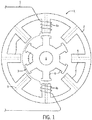
- the electrical machine 1 includes a stator 2 (e.g., laminated iron stator) that surrounds a rotor 3 in the radial direction and extends axially along rotor 3.
- the stator 2 further includes a plurality of stator poles 4, with each stator pole 4 being matched with a radially opposite stator pole to form a stator pole pair.
- Stator pole pairs 4a and 4b are wound with a phase winding 5 that may be driven in a conventional manner from a remote source (not shown). Separate phase windings, (not shown), are also included on the other stator poles 4 in a like manner.
- a stator 2 e.g., laminated iron stator
- the stator 2 further includes a plurality of stator poles 4, with each stator pole 4 being matched with a radially opposite stator pole to form a stator pole pair.
- Stator pole pairs 4a and 4b are wound with a phase winding 5 that may be driven in a conventional manner from
- the rotor 3 is formed as a salient rotor having a plurality of salient pole pieces 6.
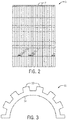
- the rotor 3 is constructed of a stack of integral laminations 7, as can be seen in the view of the rotor 3 provided in FIG. 2 , although it is recognized that the rotor core could also be formed as a single piece - with the core being machined out of steel or formed from sintered magnetic materials, for example.
- the rotor 3 includes multiple projections/teeth 6 acting as salient magnetic poles.
- a central portion of the rotor 3 includes a rotor bore 8 through which a drive shaft may be inserted, about which the rotor 3 can rotate.
- the electrical machine may be configured as a reluctance motor that induces non-permanent magnetic poles, with the phase windings 5 of the stator 3 being driven in a predetermined sequence to cause rotor 3 to rotate.
- the reluctance motor may be a synchronous reluctance motor having equal numbers of stator and rotor poles or a switched reluctance motor where the number of stator pole pairs exceeds the number of rotor pole pairs by one.
- the electrical machine may be configured as a stator permanent magnet machine (e.g., permanent magnet flux switching machine, permanent magnet flux reversal machine, or doubly-salient permanent magnet machine, for example) that includes permanent magnets 9 (shown in phantom) embedded in the stator.
- stator permanent magnet machines e.g., permanent magnet flux switching machine, permanent magnet flux reversal machine, or doubly-salient permanent magnet machine, for example
- permanent magnets 9 shown in phantom
- FIGS. 1 and 2 are meant to only illustrate examples of electrical machines that can benefit from incorporating embodiments of the invention. That is, embodiments of the invention can be implemented in a plurality of different types of electrical machines that require the use of salient poles or protruding teeth on the rotor. As such, embodiments of the invention are not meant to be limited only to the types of electrical machines shown and described herein.
- FIGS. 3 and 4 embodiments of salient rotors with which embodiments of the invention can be incorporated are shown.
- a construction of a toothed rotor 10 is shown, where a plurality of rotor teeth or poles 12 extends radially outward from an inner hub 14 or portion of the rotor with which the teeth 12 are integrally formed.
- a construction of a segmented rotor 20 is shown, where each salient rotor pole 22 is formed as a separate component from the other rotor poles. As shown in FIG.
- the separate rotor poles are arranged circumferentially around a non-magnetic rotor hub 26, with each rotor pole 22 mating with the rotor hub 26 via a mating feature 28 formed on the bottom of the rotor pole (i.e., on each lamination of the rotor pole).
- a recess 30 between each rotor pole 22 of the segmented rotor 20 is configured to receive an insert therein to be held radially between the rotor poles 22 against centrifugal force caused by rotation of the rotor, as will be described in detail further below.
- salient rotors 10, 20 such as those shown in FIGS. 3 and 4 can be made mechanically smooth by providing electrically non-conductive and non-magnetic inserts that partially fill the interpolar spaces between the rotor poles and that, in conjunction with the rotor poles, form a mechanically "smooth" outer surface on the rotor - with it being understood that “smooth” as used herein does not necessarily require that the rotor assembly outer surface to be round or completely smooth, just that the inserts traverse a distance between adjacent rotor poles to present an essentially closed surface therebetween.
- the inserts could be constructed as having a linear outer face/segment rather than an arc segment bridging adjacent rotor poles (in order to provide a cheaper insert) and that this would still be considered to present a mechanically smooth outer surface on the rotor.
- the non-conductive and non-magnetic rotor insert pieces address the issue of windage losses associated with salient rotors without affecting the magnetic performance.
- the non-conductive and non-magnetic inserts are constructed and assembled with the salient rotor in a mechanically robust way that can withstand centrifugal forces at high speeds, while minimizing the mass that is added to the rotor.
- each of the inserts is formed as a solid integral piece that extends axially through the entire length of the salient rotor.
- the rotor assembly of each embodiment includes a toothed rotor and a non-conductive, non-magnetic insert inserted in an interpolar space between each pair of adjacent rotor teeth in the toothed rotor.
- the rotor insert can have various shapes/cross-sections according to embodiments of the invention, with the shape of the inserts being adapted to the shape of the rotor poles of the particular salient rotor that is employed and the amount of centrifugal strength required to support the speed of the rotor.
- a rotor assembly 32 is provided having a toothed rotor 34 that includes rotor teeth 36 having a flange-like protrusion 38 at the radially outermost portion of each of rotor tooth 36, with the protrusion 38 extending normal to the tooth 36 on each side thereof.
- An electrically non-conductive, non-magnetic insert insert 40 is formed as a T-shaped insert positioned in an interpolar space 41 between adjacent teeth 36, with the T-shaped insert 40 having a lengthwise member 42 extending in the axial direction and a crosswise member 44 extending normally between two adjacent rotor teeth 36, with the crosswise member 44 forming a smooth outer surface on the toothed rotor 34 in combination with a pair of adjacent rotor teeth 36.
- the crosswise member 44 is formed to include a shoulder 46 on each end thereof that abuts a respective protrusion 38 on a rotor tooth, such that the protrusions 38 mate with the shoulders 46 on the T-shaped insert 40 to hold the insert in place against centrifugal forces experienced during rotor rotation.
- a mating feature 48 formed on an inner end of the lengthwise member 42.
- the mating feature 48 is configured to mate with an opening 50 formed in the back iron/inner hub 52 of the toothed rotor 34, such that the mating of the insert 40 to the toothed rotor 34 is further reinforced and the rotor assembly 32 is made more robust to centrifugal forces acting thereon.
- the mating feature 48 is configured as a dovetail feature that mates with a dovetail-shaped opening 50 to provide the increased robust to centrifugal forces; however, it is recognized that mating features of other shapes/configurations are also envisioned as being used.
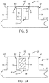
- FIG. 6 shows a rotor assembly 54 similar to that of FIG. 5 (with like elements numbered the same as in FIG. 5 ), but with the teeth 56 of a toothed rotor 58 and T-shaped inserts 60 having different features formed thereon. That is, the rotor teeth 56 are formed to each include axially-extending notches 62 formed therein in proximity to the radially outermost portion of each rotor tooth 56.
- the crosswise member 64 of the T-shaped insert 60 is formed to include a shoulder 66 on each end thereof that mates with the notches 62 of adjacent teeth 56 to hold the insert 60 in place against centrifugal force experienced during rotor rotation.
- a mating feature 48 formed on an inner end of the lengthwise member 42.
- the mating feature 48 is configured to mate with an opening 50 formed in the back iron/inner hub 52 of the toothed rotor 58, such that the mating of the insert 60 to the toothed rotor 58 is further reinforced and the rotor assembly 54 is made more robust to centrifugal forces acting thereon.
- a rotor assembly 68 having a toothed rotor 58 identical to that of the toothed rotor in FIG. 6 , with the toothed rotor 58 having rotor teeth 56 formed to each include axially-extending notches 62 formed therein in proximity to the radially outermost portion of each rotor tooth 56.
- the non-conductive, non-magnetic insert 70 of rotor assembly 68 differs from the insert 60 of rotor assembly 54 ( FIG. 6 ) - in that the insert 70 is configured to fill an entire interpolar space or gap 41 between adjacent rotor teeth 56 rather than having a T-shape that leaves part of the gap 41 open.
- the non-conductive, non-magnetic insert is formed as what is referred to here as a "hollow" insert, in that it includes an interior region that is not formed of a material of higher density.
- the "hollow” insert includes an outer shell 72 formed of a non-conductive, non-magnetic material, with the outer shell 72 defining an area or opening 73.
- the outer shell 72 is formed of a non-conductive, non-magnetic material that provides a high mechanical strength and rigidity to the insert.
- the opening 73 includes an inner filler 74 formed of a non-conductive, non-magnetic material different from that used to form outer shell 72, such that the insert 70 is formed as a multi-material insert.
- the inner filler 74 is formed of non-conductive, non-magnetic material having a lower density than the outer shell material - and is formed of a dielectric foam that is very light weight.
- inner filler 74 in the insert 70 in an interior of outer shell 72 functions to greatly reduce the overall weight of the insert 70, such that the centrifugal forces generated by the inserts 70 are greatly reduced - thereby improving the functioning and longevity of the rotor assembly 68. Additionally, inclusion of the inner filler 74 within the outer shell 72, prevents air churning and distortion during operation of the rotor assembly 68, thereby improving an efficiency thereof.
- the area 73 defined by outer shell 72 may be left open (or partially open) - such that the mass of the insert 70 is reduced. That is, in one embodiment, the opening 73 may be left entirely unfilled, as shown in FIG. 7B .
- the hollow area 73 defined by outer shell 72 could include a weight reduced structure formed therein, such as a honeycomb structure 75 extruded with the shell 72 that provides rigidity to the insert 70 while still serving to reduce the overall mass of the insert.
- the interior of the honeycomb structure 75 includes a foam material therein.
- the outer shell 72 of the insert 70 includes retaining features thereon similar to those formed on T-shaped insert 60 ( FIG. 6 ). That is, outer shell 72 includes a shoulder 66 on each end thereof that mates with the notches 62 of adjacent rotor teeth 56, as well as a mating feature 48 (e.g., a dovetail) formed on an axially inner surface thereof that mates with a corresponding opening 50 formed in the back iron/inner hub 52 of the toothed rotor 58.
- the shoulders 66 and mating feature 48 hold the insert 70 in place against centrifugal force experienced during rotor rotation and help form a rotor assembly 68 that is robust to centrifugal forces acting thereon.
- a portion of a rotor assembly 76 is shown according to another embodiment of the invention, with the rotor assembly 76 having a segmented rotor 78 formed of a plurality of separate rotor poles 80 that are mated circumferentially around a non-magnetic rotor hub 82 by way of a mating feature (e.g., dovetail feature) 84 on the rotor poles 80 that mates with an opening/receptacle 86 formed in the hub 82.
- the rotor assembly 76 also includes non-conductive, non-magnetic inserts 88 inserted between each pair of adjacent rotor poles 80 - in an interpolar gap 90 formed by the adjacent rotor poles 80.
- the non-conductive, non-magnetic inserts 88 are formed as inserts that are configured to be received in the interpolar gap 90 formed between each adjacent pair of rotor poles 80 - with the inserts 88 having a shape that conforms to that of the gaps 90.
- the inserts have a dovetail construction that enables the inserts to be held radially between the rotor poles 80 against centrifugal force caused by rotor rotation.
- the insert 88 is formed as a multi-material insert having an outer shell 90 formed of a first non-conductive, non-magnetic material and an inner filler 92 formed of a second non-conductive, non-magnetic material.
- the outer shell 90 is formed of a non-conductive, non-magnetic material that provides a high mechanical strength and rigidity to the insert.
- the inner filler 92 is formed of non-conductive, non-magnetic material having a lower density than the outer shell 90 material, a dielectric foam that is very light weight.
- inner filler 92 in the insert in an interior thereof functions to greatly reduce the overall weight of the insert 88, such that the centrifugal forces generated by the inserts 88 are greatly reduced - thereby improving the functioning and longevity of the rotor assembly 76.
- rotor assemblies 94, 96 for a toothed rotor and a segmented rotor are shown, respectively, according to additional embodiments of the invention.
- a "cage-like" assembly is provided for fastening of the rotor assembly 94, 96 and for providing additional retaining strength for the non-conductive, non-magnetic inserts 98, 100 positioned between the salient rotor poles 102, 104 of the rotors in order to make the assembly more robust.
- non-conductive, non-magnetic end plates 106 are positioned at opposing ends of the rotor assembly 94, 96 - on opposite sides of a toothed rotor or segmented rotor 112, 114 that, according to one embodiment, may be formed of a stack(s) of rotor laminations 108, 110 (or that alternatively may be formed as a single piece).
- the non-conductive, non-magnetic inserts 98, 100 that extend axially through the entire length of the stack of rotor laminations 108, 110 include a mating feature 116 formed on each end thereof that is constructed to mate with a corresponding opening 118 formed in the end plates 206.
- the mating features 116 formed on the inserts 98, 100 are received in the openings 118 formed in the end plates 106 so as to mate the inserts to the end plates and thereby form the "cage-like" rotor assembly.
- the end plates 106 function to both provide fastening of the rotor assembly 94, 96 (i.e., fastening of the stack(s) of rotor laminations 108, 110 of the toothed rotor 112 or segmented rotor 114, if the rotors are formed of laminations) and to provide additional retaining strength for the inserts 98, 100, making the rotor assemblies 94, 96 more robust.
- embodiments of the invention thus provide non-conductive, non-magnetic rotor inserts that provide smoothing for various types of salient rotors.
- the rotor inserts enable significant reduction of friction and windage losses, as the rotor surface becomes mechanically smooth based on the positioning of the inserts between adjacent pairs of rotor poles, so as to provide a significant efficiency improvement (i.e., better efficiency than a non-smooth rotor), especially for high-speed applications.
- the non-conductive, non-magnetic rotor inserts are assembled with the salient rotor in a mechanically robust way, such as via the use of mating (e.g., dovetail) features on the inserts, that enable the inserts to withstand centrifugal forces at high speeds.
- the non-conductive, non-magnetic rotor inserts are further constructed to minimize the mass that is added to the rotor, with the inserts being formed to fill only a portion of an interpolar between adjacent rotor poles and/or being formed partially of a low-density material.
- an electrical machine includes a stator and a rotor assembly disposed within the stator and configured to rotate relative to the stator, wherein the rotor assembly comprises a rotor core comprising a plurality of salient rotor poles that are spaced apart from one another around an inner hub such that an interpolar gap is formed between each adjacent pair of salient rotor poles, with an opening being defined by the rotor core in each interpolar gap, and a plurality of inserts positioned in the gaps formed between the plurality of salient rotor poles, the plurality of inserts being formed of electrically non-conductive and non-magnetic material.
- Each of the plurality of inserts comprises a mating feature formed an axially inner edge thereof that is configured to mate with a respective opening being defined by the rotor core, so as to secure the insert to the rotor core against centrifugal force experienced during rotation of the rotor assembly.
- a method for manufacturing an electrical machine includes providing a stator and providing a rotor assembly that is positionable within the stator and is mountable for rotation about a central axis, wherein providing the rotor assembly comprises providing a salient rotor core comprising a plurality of salient rotor poles that are spaced apart from one another around an inner hub such that an interpolar gap is formed between each adjacent pair of salient rotor poles, with a dovetail-shaped opening being defined by the rotor core in each interpolar gap.
- Providing the rotor assembly further comprises providing a plurality of inserts formed of electrically non-conductive and non-magnetic material and securing the plurality of inserts in the interpolar gaps formed between the plurality of salient rotor poles, wherein, in securing each of the plurality of inserts in an interpolar gap formed between an adjacent pair of salient rotor poles, a mating feature of the insert is mated with a respective opening being defined by the rotor core, so as to secure the insert to the rotor core against centrifugal force experienced during rotation of the rotor assembly.
- a rotor assembly for an electrical machine includes a salient rotor comprising a plurality of salient rotor poles that are spaced apart from one another around an inner hub such that an interpolar gap is formed between each adjacent pair of salient rotor poles and a plurality of inserts positioned in the interpolar gaps formed between the plurality of salient rotor poles and being constructed such that the plurality of inserts in combination with the plurality of salient rotor poles forms a smooth outer surface on the rotor assembly.
- the plurality of inserts comprise one of T-shaped inserts formed of an electrically non-conductive and non-magnetic material, hollow inserts having an outer shell formed of an electrically non-conductive and non-magnetic material, or dovetail-shaped inserts formed of an electrically non-conductive and non-magnetic material.
- Each of the plurality of inserts is configured to mate with the salient rotor so as to secure the insert to the salient rotor against centrifugal force experienced during rotation of the rotor assembly.
Claims (10)
- Elektromotor (1), umfassend:einen Stator (2);eine Läuferanordnung (68), die innerhalb des Stators (2) angeordnet und konfiguriert ist, um sich relativ zum Stator (2) zu drehen, wobei die Läuferanordnung (68) umfasst:einen Läuferkern, der eine Vielzahl von Schenkelläuferpolen umfasst, die um eine innere Nabe (52) voneinander beabstandet sind, sodass zwischen jedem benachbarten Paar von Schenkelläuferpolen ein Zwischenpolspalt (41) gebildet wird, wobei eine schwalbenschwanzförmige Öffnung (50) durch den Läuferkern in jedem Zwischenpolspalt (41) definiert wird; undeine Vielzahl von Einsätzen (70), die in den Spalten (41) positioniert sind, die zwischen der Vielzahl von Schenkelläuferpolen gebildet sind, um den gesamten Spalt (41) zu füllen, wobei die Vielzahl von Einsätzen (70) aus elektrisch nichtleitendem und nichtmagnetischem Material gebildet ist;wobei jeder der Vielzahl von Einsätzen (70) ein Passungsmerkmal (48) umfasst, gebildet eine axiale innere Kante davon, das konfiguriert ist, um mit einer jeweiligen schwalbenschwanzförmigen Öffnung (50) zusammenzupassen, die durch den Läuferkern definiert ist;wobei die Vielzahl von Einsätzen (70) umfassteine äußere Schale (72), die aus einem ersten elektrisch nichtleitenden nichtmagnetischen Material gebildet ist, wobei die äußere Schale (72) darin einen Hohlraum (73) definiert, wobei:ein innerer Füllstoff (74) in dem durch die äußere Schale (72) definierten Hohlraum (73) positioniert ist, wobei der innere Füllstoff (74) aus einem zweiten nichtleitenden nichtmagnetischen Material gebildet ist, das sich von dem unterscheidet, das zur Bildung der äußeren Schale (72) verwendet wird, und das eine geringere Dichte als das erste elektrisch nichtleitende nichtmagnetische Material aufweist, und der innere Füllstoff ein dielektrischer Schaum ist;jeder der Vielzahl von Läuferzähnen (56) ein Paar axial verlaufender Kerben (62) umfasst, die in der Nähe des radial äußersten Abschnitts davon gebildet sind; unddie äußere Schale (72) an jedem Ende davon eine Schulter (66) umfasst, die konfiguriert ist, um mit dem Paar axial verlaufender Kerben (62) zusammenzupassen, die an den Läuferzähnen (56) gebildet sind, sodass die Schultern (66) und das Passungsmerkmal (48) den Einsatz (70) gegen die Zentrifugalkraft in Position halten, die während der Drehung der Läuferanordnung (68) auftritt.
- Elektrische Maschine (1) nach Anspruch 1, wobei der Läuferkern einen gezahnten Läufer (58) umfasst, wobei die Vielzahl von Schenkelläuferpolen eine Vielzahl von Läuferzähnen (56) umfasst, die einstückig mit der inneren Nabe (52) gebildet sind.
- Elektrische Maschine (1) nach einem der vorhergehenden Ansprüche, wobei das Passungsmerkmal (48) ein Schwalbenschwanzmerkmal umfasst, das konfiguriert ist, um mit der schwalbenschwanzförmigen Öffnung (50) zusammenzupassen, die in der inneren Nabe (52) des Läuferkerns gebildet ist.
- Elektrische Maschine (1) nach einem der vorhergehenden Ansprüche, wobei das Schwalbenschwanzmerkmal auf der äußeren Schale (72) gebildet ist und konfiguriert ist, um mit der schwalbenschwanzförmigen Öffnung (50) zusammenzupassen, die in der inneren Nabe (52) des Läuferkerns gebildet ist.
- Elektrische Maschine (1) nach einem der vorhergehenden Ansprüche, wobei der Läuferkern (12) einen segmentierten Läufer umfasst, wobei jeder der Vielzahl von Schenkelläuferpolen eine von den anderen Schenkelläuferpolen getrennte Komponente umfasst, und wobei die Vielzahl von Schenkelläuferpolen in Umfangsrichtung um eine nichtmagnetische innere Nabe (52) angeordnet sind und mit der nichtmagnetischen inneren Nabe (52) zusammenpassen.
- Elektrische Maschine (1) nach Anspruch 5, wobei jedes benachbarte Paar getrennter Schenkelläuferpole auf dem segmentierten Läufer einen Zwischenpolspalt (41) bildet; und
wobei jeder der Vielzahl von Einsätzen (70) eine Form aufweist, die dem Zwischenpolspalt entspricht, um mit einem jeweiligen Zwischenpolspalt (41) zusammenzupassen, der zwischen einem benachbarten Paar getrennter Schenkelläuferpole gebildet ist. - Elektrische Maschine (1) nach einem der vorhergehenden Ansprüche, wobei die Läuferanordnung (68) ferner ein Paar von Endplatten umfasst, die an gegenüberliegenden Enden des Läuferkerns positioniert sind, wobei jedes der zwei Endplattenpaare aus einem elektrisch nichtleitenden und nichtmagnetischen Material gebildet ist, und einschließlich einer Vielzahl darin gebildeter Öffnungen (50); und
wobei jeder der Vielzahl von Einsätzen (70) als ein integrales Stück gebildet ist, das sich axial über eine gesamte Länge des Läuferkerns erstreckt, wobei jedes der gegenüberliegenden Enden des Einsatzes (70) ein darauf gebildetes Passungsmerkmal (48) aufweist, das konfiguriert ist, um mit einer entsprechenden Öffnung (50) in jeder Endplatte zusammenzupassen, um eine zusätzliche Haltekraft für den Einsatz (70) gegen die Zentrifugalkraft bereitzustellen, die während der Drehung der Läuferanordnung (68) auftritt. - Verfahren zum Herstellen einer elektrischen Maschine (1), wobei das Verfahren umfasst:Bereitstellen eines Stators (2);Bereitstellen einer Läuferanordnung (68), die innerhalb des Stators (2) positionierbar ist und zur Drehung um eine Mittelachse montiert werden kann, wobei das Bereitstellen der Läuferanordnung (68) umfasst:Bereitstellen eines Läuferkerns, der eine Vielzahl von Schenkelläuferpolen umfasst, die um eine innere Nabe (52) voneinander beabstandet sind, sodass zwischen jedem benachbarten Paar von Schenkelläuferpolen ein Zwischenpolspalt (41) gebildet wird, wobei eine schwalbenschwanzförmige Öffnung (50) durch den Läuferkern in jedem Zwischenpolspalt (41) definiert wird;Bereitstellen einer Vielzahl von Einsätzen (70), die aus elektrisch nichtleitendem und nichtmagnetischem Material gebildet sind; undBefestigen der Vielzahl von Einsätzen (70) in den Zwischenpolspalten (41), die zwischen der Vielzahl von Schenkelläuferpolen gebildet sind, um den gesamten Spalt (41) zu füllen;wobei beim Befestigen jedes der Vielzahl von Einsätzen (70) in einem Zwischenpolspalt (41), der zwischen einem benachbarten Paar von Schenkelläuferpolen gebildet ist, ein Passungsmerkmal (48) des Einsatzes (70) mit einer jeweiligen Öffnung (50) zusammenpasst, die durch den Läuferkern definiert ist;Bilden einer äußeren Schale (72) mit einer Vielzahl von Einsätzen (70) aus einem ersten elektrisch nichtleitenden nichtmagnetischen Material, wobei die äußere Schale (72) einen Hohlraum (73) darin definiert, wobei das Verfahren umfasst;Bilden eines inneren Füllstoffs (74) aus einem zweiten nichtleitenden nichtmagnetischen Material, das sich von dem unterscheidet, das zur Bildung der äußeren Schale (72) verwendet wird, und mit einer geringeren Dichte als das erste elektrisch nichtleitende nichtmagnetische Material, wobei der innere Füllstoff (74) ein dielektrischer Schaum ist;Positionieren des inneren Füllmaterials in dem durch die äußere Schale (72) definierten Hohlraum (73);Befestigen der Vielzahl von Einsätzen (70) in den zwischen dem benachbarten Paar von Schenkelläuferpolen gebildeten Zwischenpolspalten (41) für jeden Einsatz (70) das Zusammenpassen einer Schulter (66) an jedem Ende der Vielzahl von Einsätzen (70) mit einem Paar axial verlängerter Kerben (62) umfasst, die in der Nähe des radial äußersten Abschnitts an den Läuferzähnen (56) gebildet sind, sodass die Schultern (66) und das Passungsmerkmal (48) den Einsatz (70) gegen die Zentrifugalkraft in Position halten, die während der Drehung der Läuferanordnung (68) auftritt.
- Verfahren nach Anspruch 8, wobei das Bereitstellen eines Schenkelläuferkerns (12) das Bereitstellen eines gezahnten Rotors (58) umfasst, wobei die Vielzahl von Schenkelläuferpolen eine Vielzahl von Läuferzähnen (56) umfasst, die einstückig mit der inneren Nabe (52) gebildet sind.
- Verfahren nach Anspruch 8 oder 9, wobei das Befestigen der Vielzahl von Einsätzen (70) in den zwischen der Vielzahl von Schenkelläuferpolen gebildeten Zwischenpolspalten (41) für jeden Einsatz (70) das Zusammenpassen eines Schwalbenschwanzmerkmals des Längselements (42) mit einer schwalbenschwanzförmigen Öffnung (50) umfasst, die in der inneren Nabe (52) des Läuferkerns gebildet ist.
Applications Claiming Priority (1)
| Application Number | Priority Date | Filing Date | Title |
|---|---|---|---|
| US13/949,406 US9520751B2 (en) | 2013-07-24 | 2013-07-24 | System and method for smoothing a salient rotor in electrical machines |
Publications (3)
| Publication Number | Publication Date |
|---|---|
| EP2840678A2 EP2840678A2 (de) | 2015-02-25 |
| EP2840678A3 EP2840678A3 (de) | 2016-06-29 |
| EP2840678B1 true EP2840678B1 (de) | 2021-07-07 |
Family
ID=51178806
Family Applications (1)
| Application Number | Title | Priority Date | Filing Date |
|---|---|---|---|
| EP14177512.2A Active EP2840678B1 (de) | 2013-07-24 | 2014-07-17 | System und Verfahren zum Glätten eines Schenkelläufers in elektrischen Maschinen |
Country Status (4)
| Country | Link |
|---|---|
| US (2) | US9520751B2 (de) |
| EP (1) | EP2840678B1 (de) |
| JP (1) | JP6475431B2 (de) |
| CN (1) | CN104348269B (de) |
Families Citing this family (9)
| Publication number | Priority date | Publication date | Assignee | Title |
|---|---|---|---|---|
| US9325269B1 (en) * | 2014-11-17 | 2016-04-26 | Hamilton Sundstrand Corporation | Two stage flux switching machine for an electrical power generation system |
| GB2600011B (en) | 2016-01-13 | 2022-10-05 | Magnomatics Ltd | Magnetic gearing with damping material in rotor |
| GB2549447A (en) * | 2016-01-13 | 2017-10-25 | Magnomatics Ltd | A magnetically geared apparatus |
| CN105720788B (zh) * | 2016-04-25 | 2019-01-29 | 江苏磁谷科技股份有限公司 | 一种大功率绕组式永磁耦合器 |
| CN106100174A (zh) * | 2016-06-14 | 2016-11-09 | 广东明阳龙源电力电子有限公司 | 一种新型的转子凸极式电机结构 |
| JP6429400B2 (ja) * | 2016-06-22 | 2018-11-28 | 本田技研工業株式会社 | ステータコア、ステータ及び回転電機 |
| US11043879B2 (en) | 2018-08-07 | 2021-06-22 | Tau Motors, Inc. | Electric motor with flux barriers |
| DE102019210028A1 (de) * | 2019-07-08 | 2021-01-14 | Brose Fahrzeugteile SE & Co. Kommanditgesellschaft, Würzburg | Elektromotor und Kühlerlüfter |
| CN112401690B (zh) * | 2019-08-23 | 2022-11-25 | 广东美的生活电器制造有限公司 | 食物处理装置 |
Citations (1)
| Publication number | Priority date | Publication date | Assignee | Title |
|---|---|---|---|---|
| EP1032115A2 (de) * | 1999-02-22 | 2000-08-30 | Kabushiki Kaisha Toshiba | Rotarische Reluktanzmaschine mit Permanentmagneten |
Family Cites Families (28)
| Publication number | Priority date | Publication date | Assignee | Title |
|---|---|---|---|---|
| US3588557A (en) * | 1969-02-19 | 1971-06-28 | Westinghouse Electric Corp | Low loss ventilation for salient pole machines |
| US4058746A (en) | 1973-01-29 | 1977-11-15 | Westinghouse Electric Corporation | Dynamoelectric machinery utilizing superconductive windings |
| FR2313794A1 (fr) | 1975-06-07 | 1976-12-31 | Kirsch Kg Bernhard | Machine electrique tournante |
| US4506181A (en) * | 1984-03-02 | 1985-03-19 | General Electric Company | Permanent magnet rotor with complete amortisseur |
| US4916346A (en) | 1987-12-28 | 1990-04-10 | General Electric Company | Composite rotor lamination for use in reluctance hompolar, and permanent magnet machines |
| US4918831A (en) | 1987-12-28 | 1990-04-24 | General Electric Company | Method of fabricating composite rotor laminations for use in reluctance, homopolar and permanent magnet machines |
| US5053666A (en) | 1988-06-06 | 1991-10-01 | General Electric Company | Construction of reluctance motors |
| US5001378A (en) | 1989-09-01 | 1991-03-19 | Rem Technologies, Inc. | Rotor with reduced windage losses |
| JPH03277145A (ja) * | 1990-03-27 | 1991-12-09 | Secoh Giken Inc | リラクタンス電動機 |
| JP3060610B2 (ja) * | 1991-07-11 | 2000-07-10 | ブラザー工業株式会社 | 可変リラクタンスモータ |
| US6005318A (en) * | 1994-02-04 | 1999-12-21 | Schelenker Enterprises Ltd. | Motor including embedded permanent-magnet rotor and method for making the same |
| US5604388A (en) * | 1994-02-16 | 1997-02-18 | Emerson Electric Co. | Switched reluctance rotor molded lug |
| GB9507272D0 (en) | 1995-04-07 | 1995-05-31 | Switched Reluctance Drives Ltd | Rotor for reluctance machines |
| GB9515111D0 (en) * | 1995-07-24 | 1995-09-20 | Switched Reluctance Drives Ltd | Improved rotor for reluctance machine |
| US5952755A (en) | 1997-03-18 | 1999-09-14 | Electric Boat Corporation | Permanent magnet motor rotor |
| JPH10322947A (ja) * | 1997-05-13 | 1998-12-04 | Nishishiba Electric Co Ltd | 突極形回転子 |
| US5932948A (en) * | 1998-09-22 | 1999-08-03 | Caterpillar Inc. | Rotor V-block assembly |
| US6274960B1 (en) | 1998-09-29 | 2001-08-14 | Kabushiki Kaisha Toshiba | Reluctance type rotating machine with permanent magnets |
| JP2001037178A (ja) * | 1999-07-16 | 2001-02-09 | Okuma Corp | 電動機の回転子 |
| US7015616B2 (en) * | 2002-04-01 | 2006-03-21 | Honeywell International, Inc. | System and method for providing coil retention in the rotor windings of a high speed generator |
| GB0209794D0 (en) * | 2002-04-30 | 2002-06-05 | Univ Newcastle | Switched reluctance electrical machine |
| JP2006246571A (ja) * | 2005-03-01 | 2006-09-14 | Nagasaki Univ | リラクタンスモータ |
| EP2200160B1 (de) * | 2007-12-27 | 2019-06-26 | Mitsubishi Electric Corporation | Rotator für einen elektrischen induktionsmotor, elektrischer induktionsmotor, kompressor, gebläse und klimaanlageneinrichtung |
| AU2009350996A1 (en) * | 2009-08-14 | 2012-03-15 | Abb Research Ltd. | Modular rotor for synchronous reluctance machine |
| GB2481853B (en) | 2010-07-09 | 2012-07-25 | Imra Europe Sas | Electric motor |
| US8232702B2 (en) * | 2010-07-30 | 2012-07-31 | Ge Aviation Systems, Llc | Apparatus for a high speed sleeveless rotor |
| KR20120134505A (ko) | 2011-06-02 | 2012-12-12 | 삼성전기주식회사 | 스위치드 릴럭턴스 모터 |
| US20160294236A1 (en) * | 2015-04-01 | 2016-10-06 | General Electric Company | System and method for supporting laminations of synchronous reluctance motors |
-
2013
- 2013-07-24 US US13/949,406 patent/US9520751B2/en active Active
-
2014
- 2014-07-17 EP EP14177512.2A patent/EP2840678B1/de active Active
- 2014-07-18 JP JP2014147258A patent/JP6475431B2/ja active Active
- 2014-07-24 CN CN201410354403.6A patent/CN104348269B/zh active Active
-
2016
- 2016-11-01 US US15/340,131 patent/US20170054335A1/en not_active Abandoned
Patent Citations (1)
| Publication number | Priority date | Publication date | Assignee | Title |
|---|---|---|---|---|
| EP1032115A2 (de) * | 1999-02-22 | 2000-08-30 | Kabushiki Kaisha Toshiba | Rotarische Reluktanzmaschine mit Permanentmagneten |
Also Published As
| Publication number | Publication date |
|---|---|
| US20170054335A1 (en) | 2017-02-23 |
| CN104348269A (zh) | 2015-02-11 |
| JP6475431B2 (ja) | 2019-02-27 |
| US9520751B2 (en) | 2016-12-13 |
| EP2840678A2 (de) | 2015-02-25 |
| JP2015027253A (ja) | 2015-02-05 |
| CN104348269B (zh) | 2019-04-02 |
| US20150028718A1 (en) | 2015-01-29 |
| EP2840678A3 (de) | 2016-06-29 |
Similar Documents
| Publication | Publication Date | Title |
|---|---|---|
| EP2840678B1 (de) | System und Verfahren zum Glätten eines Schenkelläufers in elektrischen Maschinen | |
| EP2840692B1 (de) | Permanentmagnetmaschine mit Speichen und mit reduzierten Drehmomentschwankungen und Herstellungsverfahren dafür | |
| EP2553792B1 (de) | Rotor einer elektrischen maschine mit eingebetteten permanentmagneten und elektrische maschine | |
| US10432049B2 (en) | Rotor for a rotary electric machine | |
| WO2014034344A1 (ja) | 回転電機 | |
| JP5999079B2 (ja) | 回転電機ロータ | |
| US11799337B2 (en) | Rotating electric machine | |
| EP2076957B1 (de) | Rotor für eine elektrische maschine | |
| EP2853017B1 (de) | Stator einer drehenden elektrischen maschine | |
| US20120086288A1 (en) | Electric rotating machine | |
| US20190229568A1 (en) | Synchronous reluctance type rotary electric machine | |
| US20150171673A1 (en) | System and method for retaining rotor structure in synchronous reluctance machine | |
| KR20170055003A (ko) | 고정자 및 이를 갖는 bldc 모터 | |
| US9692266B2 (en) | Spoke-type PM machine with bridge | |
| WO2015171486A1 (en) | Lamination for a permanent magnet machine | |
| CN114175464A (zh) | 电动机 | |
| CN113273057A (zh) | 具有磁通分配空隙的内置永磁体电机 | |
| EP2808984B1 (de) | Rotierende maschine vom lundell-typ | |
| EP2763284A2 (de) | Aufbauanordnung eines Permanentmagnet-Läufer für einem Generator | |
| CN109997290B (zh) | 同步磁阻型旋转电机 | |
| WO2022176829A1 (ja) | ロータ |
Legal Events
| Date | Code | Title | Description |
|---|---|---|---|
| PUAI | Public reference made under article 153(3) epc to a published international application that has entered the european phase |
Free format text: ORIGINAL CODE: 0009012 |
|
| 17P | Request for examination filed |
Effective date: 20140717 |
|
| AK | Designated contracting states |
Kind code of ref document: A2 Designated state(s): AL AT BE BG CH CY CZ DE DK EE ES FI FR GB GR HR HU IE IS IT LI LT LU LV MC MK MT NL NO PL PT RO RS SE SI SK SM TR |
|
| AX | Request for extension of the european patent |
Extension state: BA ME |
|
| PUAL | Search report despatched |
Free format text: ORIGINAL CODE: 0009013 |
|
| AK | Designated contracting states |
Kind code of ref document: A3 Designated state(s): AL AT BE BG CH CY CZ DE DK EE ES FI FR GB GR HR HU IE IS IT LI LT LU LV MC MK MT NL NO PL PT RO RS SE SI SK SM TR |
|
| AX | Request for extension of the european patent |
Extension state: BA ME |
|
| RIC1 | Information provided on ipc code assigned before grant |
Ipc: H02K 1/24 20060101AFI20160524BHEP Ipc: H02K 15/02 20060101ALI20160524BHEP Ipc: H02K 1/22 20060101ALI20160524BHEP |
|
| STAA | Information on the status of an ep patent application or granted ep patent |
Free format text: STATUS: REQUEST FOR EXAMINATION WAS MADE |
|
| R17P | Request for examination filed (corrected) |
Effective date: 20170102 |
|
| RBV | Designated contracting states (corrected) |
Designated state(s): AL AT BE BG CH CY CZ DE DK EE ES FI FR GB GR HR HU IE IS IT LI LT LU LV MC MK MT NL NO PL PT RO RS SE SI SK SM TR |
|
| STAA | Information on the status of an ep patent application or granted ep patent |
Free format text: STATUS: EXAMINATION IS IN PROGRESS |
|
| 17Q | First examination report despatched |
Effective date: 20170509 |
|
| STAA | Information on the status of an ep patent application or granted ep patent |
Free format text: STATUS: EXAMINATION IS IN PROGRESS |
|
| GRAP | Despatch of communication of intention to grant a patent |
Free format text: ORIGINAL CODE: EPIDOSNIGR1 |
|
| STAA | Information on the status of an ep patent application or granted ep patent |
Free format text: STATUS: GRANT OF PATENT IS INTENDED |
|
| INTG | Intention to grant announced |
Effective date: 20210311 |
|
| GRAS | Grant fee paid |
Free format text: ORIGINAL CODE: EPIDOSNIGR3 |
|
| GRAA | (expected) grant |
Free format text: ORIGINAL CODE: 0009210 |
|
| STAA | Information on the status of an ep patent application or granted ep patent |
Free format text: STATUS: THE PATENT HAS BEEN GRANTED |
|
| AK | Designated contracting states |
Kind code of ref document: B1 Designated state(s): AL AT BE BG CH CY CZ DE DK EE ES FI FR GB GR HR HU IE IS IT LI LT LU LV MC MK MT NL NO PL PT RO RS SE SI SK SM TR |
|
| REG | Reference to a national code |
Ref country code: GB Ref legal event code: FG4D |
|
| REG | Reference to a national code |
Ref country code: AT Ref legal event code: REF Ref document number: 1409524 Country of ref document: AT Kind code of ref document: T Effective date: 20210715 |
|
| REG | Reference to a national code |
Ref country code: DE Ref legal event code: R096 Ref document number: 602014078566 Country of ref document: DE |
|
| REG | Reference to a national code |
Ref country code: IE Ref legal event code: FG4D |
|
| REG | Reference to a national code |
Ref country code: LT Ref legal event code: MG9D |
|
| REG | Reference to a national code |
Ref country code: NL Ref legal event code: MP Effective date: 20210707 |
|
| REG | Reference to a national code |
Ref country code: AT Ref legal event code: MK05 Ref document number: 1409524 Country of ref document: AT Kind code of ref document: T Effective date: 20210707 |
|
| PG25 | Lapsed in a contracting state [announced via postgrant information from national office to epo] |
Ref country code: LT Free format text: LAPSE BECAUSE OF FAILURE TO SUBMIT A TRANSLATION OF THE DESCRIPTION OR TO PAY THE FEE WITHIN THE PRESCRIBED TIME-LIMIT Effective date: 20210707 Ref country code: BG Free format text: LAPSE BECAUSE OF FAILURE TO SUBMIT A TRANSLATION OF THE DESCRIPTION OR TO PAY THE FEE WITHIN THE PRESCRIBED TIME-LIMIT Effective date: 20211007 Ref country code: AT Free format text: LAPSE BECAUSE OF FAILURE TO SUBMIT A TRANSLATION OF THE DESCRIPTION OR TO PAY THE FEE WITHIN THE PRESCRIBED TIME-LIMIT Effective date: 20210707 Ref country code: FI Free format text: LAPSE BECAUSE OF FAILURE TO SUBMIT A TRANSLATION OF THE DESCRIPTION OR TO PAY THE FEE WITHIN THE PRESCRIBED TIME-LIMIT Effective date: 20210707 Ref country code: ES Free format text: LAPSE BECAUSE OF FAILURE TO SUBMIT A TRANSLATION OF THE DESCRIPTION OR TO PAY THE FEE WITHIN THE PRESCRIBED TIME-LIMIT Effective date: 20210707 Ref country code: PT Free format text: LAPSE BECAUSE OF FAILURE TO SUBMIT A TRANSLATION OF THE DESCRIPTION OR TO PAY THE FEE WITHIN THE PRESCRIBED TIME-LIMIT Effective date: 20211108 Ref country code: NO Free format text: LAPSE BECAUSE OF FAILURE TO SUBMIT A TRANSLATION OF THE DESCRIPTION OR TO PAY THE FEE WITHIN THE PRESCRIBED TIME-LIMIT Effective date: 20211007 Ref country code: NL Free format text: LAPSE BECAUSE OF FAILURE TO SUBMIT A TRANSLATION OF THE DESCRIPTION OR TO PAY THE FEE WITHIN THE PRESCRIBED TIME-LIMIT Effective date: 20210707 Ref country code: RS Free format text: LAPSE BECAUSE OF FAILURE TO SUBMIT A TRANSLATION OF THE DESCRIPTION OR TO PAY THE FEE WITHIN THE PRESCRIBED TIME-LIMIT Effective date: 20210707 Ref country code: SE Free format text: LAPSE BECAUSE OF FAILURE TO SUBMIT A TRANSLATION OF THE DESCRIPTION OR TO PAY THE FEE WITHIN THE PRESCRIBED TIME-LIMIT Effective date: 20210707 Ref country code: HR Free format text: LAPSE BECAUSE OF FAILURE TO SUBMIT A TRANSLATION OF THE DESCRIPTION OR TO PAY THE FEE WITHIN THE PRESCRIBED TIME-LIMIT Effective date: 20210707 |
|
| PG25 | Lapsed in a contracting state [announced via postgrant information from national office to epo] |
Ref country code: PL Free format text: LAPSE BECAUSE OF FAILURE TO SUBMIT A TRANSLATION OF THE DESCRIPTION OR TO PAY THE FEE WITHIN THE PRESCRIBED TIME-LIMIT Effective date: 20210707 Ref country code: LV Free format text: LAPSE BECAUSE OF FAILURE TO SUBMIT A TRANSLATION OF THE DESCRIPTION OR TO PAY THE FEE WITHIN THE PRESCRIBED TIME-LIMIT Effective date: 20210707 Ref country code: GR Free format text: LAPSE BECAUSE OF FAILURE TO SUBMIT A TRANSLATION OF THE DESCRIPTION OR TO PAY THE FEE WITHIN THE PRESCRIBED TIME-LIMIT Effective date: 20211008 |
|
| REG | Reference to a national code |
Ref country code: CH Ref legal event code: PL |
|
| REG | Reference to a national code |
Ref country code: BE Ref legal event code: MM Effective date: 20210731 |
|
| REG | Reference to a national code |
Ref country code: DE Ref legal event code: R097 Ref document number: 602014078566 Country of ref document: DE |
|
| PG25 | Lapsed in a contracting state [announced via postgrant information from national office to epo] |
Ref country code: LI Free format text: LAPSE BECAUSE OF NON-PAYMENT OF DUE FEES Effective date: 20210731 Ref country code: DK Free format text: LAPSE BECAUSE OF FAILURE TO SUBMIT A TRANSLATION OF THE DESCRIPTION OR TO PAY THE FEE WITHIN THE PRESCRIBED TIME-LIMIT Effective date: 20210707 Ref country code: CH Free format text: LAPSE BECAUSE OF NON-PAYMENT OF DUE FEES Effective date: 20210731 |
|
| PLBE | No opposition filed within time limit |
Free format text: ORIGINAL CODE: 0009261 |
|
| STAA | Information on the status of an ep patent application or granted ep patent |
Free format text: STATUS: NO OPPOSITION FILED WITHIN TIME LIMIT |
|
| PG25 | Lapsed in a contracting state [announced via postgrant information from national office to epo] |
Ref country code: SM Free format text: LAPSE BECAUSE OF FAILURE TO SUBMIT A TRANSLATION OF THE DESCRIPTION OR TO PAY THE FEE WITHIN THE PRESCRIBED TIME-LIMIT Effective date: 20210707 Ref country code: SK Free format text: LAPSE BECAUSE OF FAILURE TO SUBMIT A TRANSLATION OF THE DESCRIPTION OR TO PAY THE FEE WITHIN THE PRESCRIBED TIME-LIMIT Effective date: 20210707 Ref country code: RO Free format text: LAPSE BECAUSE OF FAILURE TO SUBMIT A TRANSLATION OF THE DESCRIPTION OR TO PAY THE FEE WITHIN THE PRESCRIBED TIME-LIMIT Effective date: 20210707 Ref country code: MC Free format text: LAPSE BECAUSE OF FAILURE TO SUBMIT A TRANSLATION OF THE DESCRIPTION OR TO PAY THE FEE WITHIN THE PRESCRIBED TIME-LIMIT Effective date: 20210707 Ref country code: LU Free format text: LAPSE BECAUSE OF NON-PAYMENT OF DUE FEES Effective date: 20210717 Ref country code: EE Free format text: LAPSE BECAUSE OF FAILURE TO SUBMIT A TRANSLATION OF THE DESCRIPTION OR TO PAY THE FEE WITHIN THE PRESCRIBED TIME-LIMIT Effective date: 20210707 Ref country code: CZ Free format text: LAPSE BECAUSE OF FAILURE TO SUBMIT A TRANSLATION OF THE DESCRIPTION OR TO PAY THE FEE WITHIN THE PRESCRIBED TIME-LIMIT Effective date: 20210707 Ref country code: AL Free format text: LAPSE BECAUSE OF FAILURE TO SUBMIT A TRANSLATION OF THE DESCRIPTION OR TO PAY THE FEE WITHIN THE PRESCRIBED TIME-LIMIT Effective date: 20210707 |
|
| 26N | No opposition filed |
Effective date: 20220408 |
|
| GBPC | Gb: european patent ceased through non-payment of renewal fee |
Effective date: 20211007 |
|
| PG25 | Lapsed in a contracting state [announced via postgrant information from national office to epo] |
Ref country code: IT Free format text: LAPSE BECAUSE OF FAILURE TO SUBMIT A TRANSLATION OF THE DESCRIPTION OR TO PAY THE FEE WITHIN THE PRESCRIBED TIME-LIMIT Effective date: 20210707 Ref country code: IE Free format text: LAPSE BECAUSE OF NON-PAYMENT OF DUE FEES Effective date: 20210717 Ref country code: GB Free format text: LAPSE BECAUSE OF NON-PAYMENT OF DUE FEES Effective date: 20211007 Ref country code: FR Free format text: LAPSE BECAUSE OF NON-PAYMENT OF DUE FEES Effective date: 20210907 Ref country code: BE Free format text: LAPSE BECAUSE OF NON-PAYMENT OF DUE FEES Effective date: 20210731 |
|
| PG25 | Lapsed in a contracting state [announced via postgrant information from national office to epo] |
Ref country code: HU Free format text: LAPSE BECAUSE OF FAILURE TO SUBMIT A TRANSLATION OF THE DESCRIPTION OR TO PAY THE FEE WITHIN THE PRESCRIBED TIME-LIMIT; INVALID AB INITIO Effective date: 20140717 |
|
| PG25 | Lapsed in a contracting state [announced via postgrant information from national office to epo] |
Ref country code: CY Free format text: LAPSE BECAUSE OF FAILURE TO SUBMIT A TRANSLATION OF THE DESCRIPTION OR TO PAY THE FEE WITHIN THE PRESCRIBED TIME-LIMIT Effective date: 20210707 |
|
| P01 | Opt-out of the competence of the unified patent court (upc) registered |
Effective date: 20230528 |
|
| PGFP | Annual fee paid to national office [announced via postgrant information from national office to epo] |
Ref country code: DE Payment date: 20230620 Year of fee payment: 10 |
|
| PG25 | Lapsed in a contracting state [announced via postgrant information from national office to epo] |
Ref country code: MK Free format text: LAPSE BECAUSE OF FAILURE TO SUBMIT A TRANSLATION OF THE DESCRIPTION OR TO PAY THE FEE WITHIN THE PRESCRIBED TIME-LIMIT Effective date: 20210707 |