EP2840586A1 - Selbsthemmende Druckfeder mit Gehäuse - Google Patents
Selbsthemmende Druckfeder mit Gehäuse Download PDFInfo
- Publication number
- EP2840586A1 EP2840586A1 EP14166595.0A EP14166595A EP2840586A1 EP 2840586 A1 EP2840586 A1 EP 2840586A1 EP 14166595 A EP14166595 A EP 14166595A EP 2840586 A1 EP2840586 A1 EP 2840586A1
- Authority
- EP
- European Patent Office
- Prior art keywords
- compression spring
- recessed chamber
- spring
- housing
- tas
- Prior art date
- Legal status (The legal status is an assumption and is not a legal conclusion. Google has not performed a legal analysis and makes no representation as to the accuracy of the status listed.)
- Withdrawn
Links
- 230000006835 compression Effects 0.000 title claims abstract description 83
- 238000007906 compression Methods 0.000 title claims abstract description 83
- 230000014759 maintenance of location Effects 0.000 claims abstract description 4
- 239000000463 material Substances 0.000 claims description 5
- 238000003780 insertion Methods 0.000 claims description 3
- 230000037431 insertion Effects 0.000 claims description 3
- 230000008878 coupling Effects 0.000 description 7
- 238000010168 coupling process Methods 0.000 description 7
- 238000005859 coupling reaction Methods 0.000 description 7
- 230000006870 function Effects 0.000 description 5
- 238000004519 manufacturing process Methods 0.000 description 4
- 230000008901 benefit Effects 0.000 description 3
- 239000003292 glue Substances 0.000 description 3
- 230000000694 effects Effects 0.000 description 2
- 230000007257 malfunction Effects 0.000 description 2
- 230000007246 mechanism Effects 0.000 description 2
- 239000002184 metal Substances 0.000 description 2
- 238000000034 method Methods 0.000 description 2
- 230000008569 process Effects 0.000 description 2
- 238000004804 winding Methods 0.000 description 2
- SYUPLLHVMCLXEM-UHFFFAOYSA-N 4,5-dichloro-2-(3-methylphenyl)pyridazin-3-one Chemical compound CC1=CC=CC(N2C(C(Cl)=C(Cl)C=N2)=O)=C1 SYUPLLHVMCLXEM-UHFFFAOYSA-N 0.000 description 1
- 239000004593 Epoxy Substances 0.000 description 1
- 230000009471 action Effects 0.000 description 1
- 238000004026 adhesive bonding Methods 0.000 description 1
- 238000004140 cleaning Methods 0.000 description 1
- 238000005238 degreasing Methods 0.000 description 1
- 230000001419 dependent effect Effects 0.000 description 1
- 238000009434 installation Methods 0.000 description 1
- 239000006082 mold release agent Substances 0.000 description 1
- 238000000465 moulding Methods 0.000 description 1
- 238000010137 moulding (plastic) Methods 0.000 description 1
- 239000004033 plastic Substances 0.000 description 1
- 230000000135 prohibitive effect Effects 0.000 description 1
- 239000002990 reinforced plastic Substances 0.000 description 1
Images


Classifications
-
- F—MECHANICAL ENGINEERING; LIGHTING; HEATING; WEAPONS; BLASTING
- F16—ENGINEERING ELEMENTS AND UNITS; GENERAL MEASURES FOR PRODUCING AND MAINTAINING EFFECTIVE FUNCTIONING OF MACHINES OR INSTALLATIONS; THERMAL INSULATION IN GENERAL
- F16F—SPRINGS; SHOCK-ABSORBERS; MEANS FOR DAMPING VIBRATION
- F16F1/00—Springs
- F16F1/02—Springs made of steel or other material having low internal friction; Wound, torsion, leaf, cup, ring or the like springs, the material of the spring not being relevant
- F16F1/04—Wound springs
- F16F1/06—Wound springs with turns lying in cylindrical surfaces
-
- F—MECHANICAL ENGINEERING; LIGHTING; HEATING; WEAPONS; BLASTING
- F16—ENGINEERING ELEMENTS AND UNITS; GENERAL MEASURES FOR PRODUCING AND MAINTAINING EFFECTIVE FUNCTIONING OF MACHINES OR INSTALLATIONS; THERMAL INSULATION IN GENERAL
- F16F—SPRINGS; SHOCK-ABSORBERS; MEANS FOR DAMPING VIBRATION
- F16F1/00—Springs
- F16F1/02—Springs made of steel or other material having low internal friction; Wound, torsion, leaf, cup, ring or the like springs, the material of the spring not being relevant
- F16F1/04—Wound springs
- F16F1/12—Attachments or mountings
- F16F1/125—Attachments or mountings where the end coils of the spring engage an axial insert
-
- F—MECHANICAL ENGINEERING; LIGHTING; HEATING; WEAPONS; BLASTING
- F16—ENGINEERING ELEMENTS AND UNITS; GENERAL MEASURES FOR PRODUCING AND MAINTAINING EFFECTIVE FUNCTIONING OF MACHINES OR INSTALLATIONS; THERMAL INSULATION IN GENERAL
- F16F—SPRINGS; SHOCK-ABSORBERS; MEANS FOR DAMPING VIBRATION
- F16F1/00—Springs
- F16F1/36—Springs made of rubber or other material having high internal friction, e.g. thermoplastic elastomers
- F16F1/366—Springs made of rubber or other material having high internal friction, e.g. thermoplastic elastomers made of fibre-reinforced plastics, i.e. characterised by their special construction from such materials
- F16F1/3665—Wound springs
-
- H—ELECTRICITY
- H01—ELECTRIC ELEMENTS
- H01H—ELECTRIC SWITCHES; RELAYS; SELECTORS; EMERGENCY PROTECTIVE DEVICES
- H01H3/00—Mechanisms for operating contacts
- H01H3/22—Power arrangements internal to the switch for operating the driving mechanism
- H01H3/30—Power arrangements internal to the switch for operating the driving mechanism using spring motor
- H01H3/3052—Linear spring motors
-
- H—ELECTRICITY
- H01—ELECTRIC ELEMENTS
- H01H—ELECTRIC SWITCHES; RELAYS; SELECTORS; EMERGENCY PROTECTIVE DEVICES
- H01H71/00—Details of the protective switches or relays covered by groups H01H73/00 - H01H83/00
- H01H71/02—Housings; Casings; Bases; Mountings
- H01H71/0207—Mounting or assembling the different parts of the circuit breaker
- H01H71/0228—Mounting or assembling the different parts of the circuit breaker having provisions for interchangeable or replaceable parts
Definitions
- the present invention is directed to compression springs which are used to various applications, and in particular for operate accessory linkages, wherein springs are fully secured at one end while the other end cannot be secured or wherein the other end of the spring would be cost prohibitive because such a design would require additional parts, mountings, or incur the added cost of tooling, and molds for over-molding.
- circuit breakers are used to protect lives and personal property, and as such require that the design is safe and reliable.
- circuit breakers are composed of various components and among those components are springs used for various compression and extension type applications.
- the first end of the spring can be bonded or glued inside a guided seat.
- the reliability of the bonding joint which highly depends on the degreasing and cleaning mold release agent use during manufacture and assembly as well as the oxide on stored parts.
- the reliability and added costs of the product are affected by the selection of the proper bonder or primer, the added cost of a curing time for the epoxy, the application of the glue which can at times unreliably bond more than the 1st loop, and glue the 2nd or 3rd loop so as to impede the proper function of the spring-since it in effect reduces the number of active coils. All of the above would also apply to an insertion plastic molding process, where one end of the spring would be secured by being over-molded embedded with plastic in the mold.
- a compression spring according to the invention comprises a length of coiled wire having substantially a circular cross-sectional area, wherein at least a first end of the compression spring is formed as a retainer means.
- the retainer means is configured for being compressed while being mounted into a recessed chamber and for expanding when inserted into the recessed chamber in a way to fix the compression spring in the recessed chamber.
- This compression spring has the advantage that it can be easily fixed to a housing without the need of extra parts or glue for fixation.
- the retainer means functions like a snap-in mechanism and is, therefore, easy to install and provides for a reliable, releasable fixation of the compression spring to the housing.
- the retainer means is formed as a v-shaped locking hook and the compression spring is an LCS compression spring.
- Such locking hook has good snap-in properties, is easy to manufacture and easy to install at a respective recessed chamber of a housing.
- the locking hook substantially extends parallel to a center axis of a coiled portion of the LCS compression spring.
- the compression spring can be installed in a housing in a mounting direction that is parallel to a center axis of a coiled portion of the compression spring until the locking hook snaps-in a recessed chamber of the housing.
- the retainer means is formed as a retainer loop and the compression spring is a TAS compression spring.
- a center axis of the retainer loop is substantially parallel to a center axis of a coiled portion of the TAS compression spring.
- the TAS compression spring can be installed into a housing in a mounting direction that is perpendicular to the center axis of the coiled portion of the TAS compression spring until the locking hook snaps-in a recessed chamber of the housing.
- the compression spring is made from a flexible material having an elastic memory.
- the snap-in action of the retainer means and thereby a reliable and releasable fixation of the compression spring in a housing is ensured.
- the compression spring retention system comprises a compression spring according to the invention and a spring housing having a recessed chamber with an opening for insertion of the retainer means of the compression spring there through.
- the housing is configured such that during mounting of the retainer means into the recessed chamber, the retainer means is compressed and expands when entering the recessed chamber and thereby fixing the compression spring to the housing.
- the present invention focuses on a compression spring wherein one end is secured within a housing of a circuit breaker.
- the compression spring comprises a helical design made of several coils that are compressed or expanded upon application.
- the compression spring generally includes a locking hook (3) or retainer loop to function as means for securing one end of the compression spring within a given space.
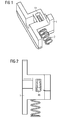
- the present invention includes the use of a locking hook 3 as best shown in ( Fig. 1, 2 and 4 ), and a retainer loop 11 in ( Fig. 7 through Fig. 11 ) on one end of the classic compression spring.
- the present invention is described best in the representations shown in Figs. 1-11 . More specifically, the present invention in one embodiment may be described with reference and description of a coupling LCS (Leading Changeover Switch) with LCS compression spring 2 assembly ( Fig. 1, 2 , 5 ), where LCS compression spring 2 has a locking hook 3.
- LCS Leading Changeover Switch
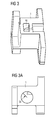
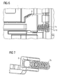
- the coupling LCS 1 or any other housing is equipped with a recessed chamber 4 as shown in Fig. 5 , which accommodates the locking hook 3.
- the installation of the LCS compression spring is as follows.
- the locking hook 3 is inserted through the spring guide 5a ( Fig. 3A ) half way into the quadrant Shaped through hole 5 in ( Fig. 3 ).
- the screwdriver/tool is used to pull the rest (the second half) of the locking hook 3 inside the recessed chamber 4 as far as the hook reaches the recessed chamber back wall 4a ( Fig. 1 ).
- the locking hook 3 After the locking hook 3 is squeezed (the leg of the locking hook 3 or v-shaped compressible section) through a quadrant shaped through hole, the locking hook 3 springs open (the retention section expands) and secures the LCS compression spring 2 inside recessed chamber 4 in ( Fig. 1, 2 , 5 ).
- the compression spring may be made from a variety of materials of a metal, reinforced plastic or any other material having the ability to compress and regain substantially its original shape. Normally, these compression springs are made of metal, from wires of specific gauges which are then coiled into a helical shape.
- the end windings in the instant invention (locking Hook 3 and retainer loop 11) are especially configured to connect with the space within the recessed chamber 4 or cavity so as to provide a friction fit, or resistance from side walls of the cavity or the walls in the recessed chamber.
- the cavity used in the second embodiment below comprises a groove used to retain the retainer loop in place within the cavity portion.
- the compression spring maybe have a circular cross-sectional area, or an elliptical cross-sectional area, or any other cross sectional area capable of withstanding the stress and/or strain generated from the constant compression or release of the compression spring.
- the spring is contemplated to have the property of resisting deformation so as to rebound or retain substantially its shape.
- the spring is preferred to be made as a unitary structure, the spring may be made off several coils attached by various means to different shaped end windings to perform various additional functions.
- the spring can also be made from a flexible reinforced material which like the wired version would have deformation resistant properties, but also having (like the wire spring), an elastic memory so as to regain its shape after be back in its free form (no load condition).
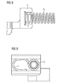
- the present invention maybe used with reference and description to a TAS actuation bar 8 with TAS compression spring 7, 7a, 7b assembly as best shown in Fig. 6-10 .
- the TAS compression spring 7, 7a, 7b has a retainer loop 11 as shown in Fig. 7-11 .
- the TAS actuation bar 8 or any other housing is equipped with a groove 9 (TAS actuation bar 8) which accommodates the spring's retainer loop 11 as shown in ( Fig. 8 , 10 ).
- the retainer loop 11 is inserted into the cavity of the TAS actuation bar 8 and since the retainer loop 11 and the remaining coils are substantially perpendicular (although any other angle will suffice), the active coils are mounted on a pole/mount so as to help secure the end of the TAS compression spring 7, 7a, 7b in place, prevent rotation of the TAS compression spring 7, 7a, 7b and direct the orientation of the coils.
- the groove 9 allows for portions of the retainer loop 11 to rest against the groove 9 walls.
- the retainer loop portion of the TAS compression spring 7, 7a, 7b exerts a force by its opposition to compression so as to secure the TAS compression spring 7, 7a, 7b more reliably.
Landscapes
- Engineering & Computer Science (AREA)
- General Engineering & Computer Science (AREA)
- Mechanical Engineering (AREA)
- Springs (AREA)
Priority Applications (1)
| Application Number | Priority Date | Filing Date | Title |
|---|---|---|---|
| US14/306,300 US9593730B2 (en) | 2013-08-21 | 2014-06-17 | Self-retention compression spring with housing |
Applications Claiming Priority (1)
| Application Number | Priority Date | Filing Date | Title |
|---|---|---|---|
| US201361868106P | 2013-08-21 | 2013-08-21 |
Publications (1)
| Publication Number | Publication Date |
|---|---|
| EP2840586A1 true EP2840586A1 (de) | 2015-02-25 |
Family
ID=50677968
Family Applications (1)
| Application Number | Title | Priority Date | Filing Date |
|---|---|---|---|
| EP14166595.0A Withdrawn EP2840586A1 (de) | 2013-08-21 | 2014-04-30 | Selbsthemmende Druckfeder mit Gehäuse |
Country Status (2)
| Country | Link |
|---|---|
| US (1) | US9593730B2 (de) |
| EP (1) | EP2840586A1 (de) |
Citations (10)
| Publication number | Priority date | Publication date | Assignee | Title |
|---|---|---|---|---|
| FR2410183A1 (fr) * | 1977-11-23 | 1979-06-22 | Normandie Atel Metallurg Meca | Ressort pour assemblage de tubes |
| GB2026246A (en) * | 1978-07-21 | 1980-01-30 | Delta Materials Research Ltd | Electrical circuit-breaker |
| JPS62209201A (ja) * | 1986-03-07 | 1987-09-14 | Aisin Warner Ltd | アキユムレ−タ |
| JPH0252259U (de) * | 1988-10-06 | 1990-04-16 | ||
| EP0437220A2 (de) * | 1990-01-12 | 1991-07-17 | Mitsubishi Denki Kabushiki Kaisha | Schalter mit Fehlerstrom erkennenden Funktionen |
| JPH0681870A (ja) * | 1992-09-07 | 1994-03-22 | Aisan Ind Co Ltd | テンションスプリング |
| DE19937488A1 (de) * | 1999-08-07 | 2001-02-08 | Volkswagen Ag | Elastisches Halterungselement |
| DE19943629A1 (de) * | 1999-09-11 | 2001-03-15 | Stihl Maschf Andreas | Schwingungsdämpfer |
| JP2001206640A (ja) * | 2000-01-27 | 2001-07-31 | Iris Ohyama Inc | ホースリール |
| EP2355121A2 (de) * | 2010-01-27 | 2011-08-10 | LS Industrial Systems Co., Ltd | Schutzschalter mit Anzeigemechanismus der Auslösungsursache |
Family Cites Families (2)
| Publication number | Priority date | Publication date | Assignee | Title |
|---|---|---|---|---|
| DE8522254U1 (de) * | 1985-08-02 | 1985-09-26 | Ellenberger & Poensgen Gmbh, 8503 Altdorf | Überstromschutzschalter |
| JP2012036418A (ja) * | 2010-08-03 | 2012-02-23 | Chuo Spring Co Ltd | 高強度ばねとその製造方法 |
-
2014
- 2014-04-30 EP EP14166595.0A patent/EP2840586A1/de not_active Withdrawn
- 2014-06-17 US US14/306,300 patent/US9593730B2/en not_active Expired - Fee Related
Patent Citations (10)
| Publication number | Priority date | Publication date | Assignee | Title |
|---|---|---|---|---|
| FR2410183A1 (fr) * | 1977-11-23 | 1979-06-22 | Normandie Atel Metallurg Meca | Ressort pour assemblage de tubes |
| GB2026246A (en) * | 1978-07-21 | 1980-01-30 | Delta Materials Research Ltd | Electrical circuit-breaker |
| JPS62209201A (ja) * | 1986-03-07 | 1987-09-14 | Aisin Warner Ltd | アキユムレ−タ |
| JPH0252259U (de) * | 1988-10-06 | 1990-04-16 | ||
| EP0437220A2 (de) * | 1990-01-12 | 1991-07-17 | Mitsubishi Denki Kabushiki Kaisha | Schalter mit Fehlerstrom erkennenden Funktionen |
| JPH0681870A (ja) * | 1992-09-07 | 1994-03-22 | Aisan Ind Co Ltd | テンションスプリング |
| DE19937488A1 (de) * | 1999-08-07 | 2001-02-08 | Volkswagen Ag | Elastisches Halterungselement |
| DE19943629A1 (de) * | 1999-09-11 | 2001-03-15 | Stihl Maschf Andreas | Schwingungsdämpfer |
| JP2001206640A (ja) * | 2000-01-27 | 2001-07-31 | Iris Ohyama Inc | ホースリール |
| EP2355121A2 (de) * | 2010-01-27 | 2011-08-10 | LS Industrial Systems Co., Ltd | Schutzschalter mit Anzeigemechanismus der Auslösungsursache |
Also Published As
| Publication number | Publication date |
|---|---|
| US9593730B2 (en) | 2017-03-14 |
| US20150054208A1 (en) | 2015-02-26 |
Similar Documents
| Publication | Publication Date | Title |
|---|---|---|
| JP4971329B2 (ja) | ウインドシールドワイパ装置 | |
| US9855910B2 (en) | Securing device for a folded airbag and airbag module | |
| JP5891961B2 (ja) | グロメット及びグロメット付ワイヤーハーネス | |
| JP6363564B2 (ja) | スモールフォームファクタ圧力センサ | |
| CN108431627B (zh) | 超声波传感器 | |
| JP6345970B2 (ja) | 部品ユニット | |
| JP6265943B2 (ja) | 流体制御弁 | |
| EP3178707B1 (de) | Lenkrad | |
| CN104798217B (zh) | 将机械功转变为电能的组件和包括该组件的计数装置 | |
| US9267610B2 (en) | Hydraulic pressure control device | |
| JP2016038378A5 (de) | ||
| EP2667393B1 (de) | Schalter | |
| JP4308531B2 (ja) | エレクトロハイドロリック式の圧力制御装置 | |
| EP2840586A1 (de) | Selbsthemmende Druckfeder mit Gehäuse | |
| JP2018006383A (ja) | コイル装置 | |
| KR101979167B1 (ko) | 발음기 | |
| CN100570784C (zh) | 开关装置 | |
| US20230170161A1 (en) | Electrical connector assemblies | |
| CN105409338B (zh) | 控制器和具有控制器的装置 | |
| CN111344934A (zh) | 旋转电机 | |
| CN115638893A (zh) | 具有基于印刷电路板的触点的传感器 | |
| CN219774512U (zh) | 连接结构、结构组件以及终端设备 | |
| CN111164833B (zh) | 用于电传感器连接的锁定夹 | |
| CN111164387A (zh) | 用于传感器安装的弹簧夹 | |
| KR200429935Y1 (ko) | 전장품용 버튼스위치의 고정 구조 |
Legal Events
| Date | Code | Title | Description |
|---|---|---|---|
| PUAI | Public reference made under article 153(3) epc to a published international application that has entered the european phase |
Free format text: ORIGINAL CODE: 0009012 |
|
| 17P | Request for examination filed |
Effective date: 20140430 |
|
| AK | Designated contracting states |
Kind code of ref document: A1 Designated state(s): AL AT BE BG CH CY CZ DE DK EE ES FI FR GB GR HR HU IE IS IT LI LT LU LV MC MK MT NL NO PL PT RO RS SE SI SK SM TR |
|
| AX | Request for extension of the european patent |
Extension state: BA ME |
|
| R17P | Request for examination filed (corrected) |
Effective date: 20150820 |
|
| RBV | Designated contracting states (corrected) |
Designated state(s): AL AT BE BG CH CY CZ DE DK EE ES FI FR GB GR HR HU IE IS IT LI LT LU LV MC MK MT NL NO PL PT RO RS SE SI SK SM TR |
|
| 17Q | First examination report despatched |
Effective date: 20170316 |
|
| RAP1 | Party data changed (applicant data changed or rights of an application transferred) |
Owner name: SIEMENS AKTIENGESELLSCHAFT |
|
| STAA | Information on the status of an ep patent application or granted ep patent |
Free format text: STATUS: THE APPLICATION IS DEEMED TO BE WITHDRAWN |
|
| 18D | Application deemed to be withdrawn |
Effective date: 20200603 |