EP2840554B1 - Procédé et capteur radio pour la localisation d'une unité embarquée - Google Patents
Procédé et capteur radio pour la localisation d'une unité embarquée Download PDFInfo
- Publication number
- EP2840554B1 EP2840554B1 EP13181570.6A EP13181570A EP2840554B1 EP 2840554 B1 EP2840554 B1 EP 2840554B1 EP 13181570 A EP13181570 A EP 13181570A EP 2840554 B1 EP2840554 B1 EP 2840554B1
- Authority
- EP
- European Patent Office
- Prior art keywords
- radio
- identifier
- obu
- board unit
- tid
- Prior art date
- Legal status (The legal status is an assumption and is not a legal conclusion. Google has not performed a legal analysis and makes no representation as to the accuracy of the status listed.)
- Active
Links
- 238000000034 method Methods 0.000 title claims description 29
- 230000005540 biological transmission Effects 0.000 claims description 37
- 230000004807 localization Effects 0.000 claims description 36
- 230000004044 response Effects 0.000 claims description 33
- 230000035945 sensitivity Effects 0.000 claims description 19
- 230000015654 memory Effects 0.000 claims description 12
- 238000006243 chemical reaction Methods 0.000 claims description 3
- 238000004891 communication Methods 0.000 description 16
- 230000006870 function Effects 0.000 description 3
- 230000008901 benefit Effects 0.000 description 2
- 230000001419 dependent effect Effects 0.000 description 2
- 238000010586 diagram Methods 0.000 description 2
- 238000005259 measurement Methods 0.000 description 2
- 230000008569 process Effects 0.000 description 2
- 238000012217 deletion Methods 0.000 description 1
- 230000037430 deletion Effects 0.000 description 1
- 238000001514 detection method Methods 0.000 description 1
- 238000011161 development Methods 0.000 description 1
- 238000005516 engineering process Methods 0.000 description 1
- 238000011156 evaluation Methods 0.000 description 1
- 238000012986 modification Methods 0.000 description 1
- 230000004048 modification Effects 0.000 description 1
- 238000012545 processing Methods 0.000 description 1
Images


Classifications
-
- H—ELECTRICITY
- H04—ELECTRIC COMMUNICATION TECHNIQUE
- H04W—WIRELESS COMMUNICATION NETWORKS
- H04W88/00—Devices specially adapted for wireless communication networks, e.g. terminals, base stations or access point devices
- H04W88/08—Access point devices
-
- H—ELECTRICITY
- H04—ELECTRIC COMMUNICATION TECHNIQUE
- H04W—WIRELESS COMMUNICATION NETWORKS
- H04W64/00—Locating users or terminals or network equipment for network management purposes, e.g. mobility management
- H04W64/003—Locating users or terminals or network equipment for network management purposes, e.g. mobility management locating network equipment
-
- G—PHYSICS
- G07—CHECKING-DEVICES
- G07B—TICKET-ISSUING APPARATUS; FARE-REGISTERING APPARATUS; FRANKING APPARATUS
- G07B15/00—Arrangements or apparatus for collecting fares, tolls or entrance fees at one or more control points
- G07B15/06—Arrangements for road pricing or congestion charging of vehicles or vehicle users, e.g. automatic toll systems
- G07B15/063—Arrangements for road pricing or congestion charging of vehicles or vehicle users, e.g. automatic toll systems using wireless information transmission between the vehicle and a fixed station
-
- H—ELECTRICITY
- H04—ELECTRIC COMMUNICATION TECHNIQUE
- H04B—TRANSMISSION
- H04B1/00—Details of transmission systems, not covered by a single one of groups H04B3/00 - H04B13/00; Details of transmission systems not characterised by the medium used for transmission
- H04B1/38—Transceivers, i.e. devices in which transmitter and receiver form a structural unit and in which at least one part is used for functions of transmitting and receiving
- H04B1/3822—Transceivers, i.e. devices in which transmitter and receiver form a structural unit and in which at least one part is used for functions of transmitting and receiving specially adapted for use in vehicles
-
- H—ELECTRICITY
- H04—ELECTRIC COMMUNICATION TECHNIQUE
- H04W—WIRELESS COMMUNICATION NETWORKS
- H04W4/00—Services specially adapted for wireless communication networks; Facilities therefor
- H04W4/80—Services using short range communication, e.g. near-field communication [NFC], radio-frequency identification [RFID] or low energy communication
-
- H—ELECTRICITY
- H04—ELECTRIC COMMUNICATION TECHNIQUE
- H04W—WIRELESS COMMUNICATION NETWORKS
- H04W52/00—Power management, e.g. TPC [Transmission Power Control], power saving or power classes
- H04W52/04—TPC
Definitions
- the present invention relates to a method for locating an on-board unit in an area around a radio beacon.
- the invention further relates to a radio beacon for such a method.
- OBUs on-board units
- a multiplicity of radio beacons are distributed over the road network, each of which has a limited radio coverage area in which they can communicate with the OBUs of passing vehicles via radio, with a successful radio communication locating the OBU on the radio coverage area.
- the communication of the OBU with the beacon may be based on DSRC (Dedicated Short Range Communication), WAVE (Wireless Access for Vehicle Environment), RFID (Radio Frequency Identification) or similar technologies, and the OBUs may accordingly be of active or passive (transponder) type be.
- each lane is assigned its own beacon.
- the radio coverage area (the communication zone) of the respective radio beacon must be best limited by adapting the transmission strength of the radio beacon to the reception sensitivity of the OBU (and vice versa) on the lane to the response or detection of vehicle OBUs on neighboring lanes (so-called ". cross-talk ").
- This problem is particularly important for single lane lanes, since responding to a vehicle on a lane, eg an oncoming lane, would interfere with operation, or in multi-lane lanes where lane assignment is important, eg HOV (FIG. high occupancy vehicle) lanes.
- the WO 2010/105349 A1 shows a communication system between an antenna and an OBU.
- the OBU sends a message indicating its OBU type to the antenna, whereupon it can locate the OBU by means of the received OBU type and a measured received signal strength of the message.
- the EP 2 363 826 A2 shows the location of RFID tags from which an identifier is read out.
- the localization of the RFID tags is done by reading a parameter associated with the identifier.
- the US 7385525 B2 shows a method for locating a vehicle on a lane by handshakes between an antenna and an OBU of the vehicle.
- the invention has as its object to solve these problems and to provide a method and a radio beacon which can safely locate an OBU within a predetermined range, e.g. a specific lane of a roadway to allow the radio beacon.
- the localization process takes into account individual, for each OBU specific radio characteristics, which are pre-stored in a database. If the identifier does not identify an individual OBU - which is possible - but only its type, generalized radio characteristics for a particular OBU type can be held in the database and used for localization. If, for example, a new type of OBU comes onto the market and is used in the road toll system, it is sufficient to store an appropriate type identifier and its specific radio property (s) in the database. An expansion of a road system to any type of OBUs and their radio transceiver or transponder chips is thus nothing contrary, as long as they are known to the database.
- the method of the invention can be applied very easily to existing devices for localizing an OBU, for example in road traffic, by connecting them to a corresponding database and adapting the radio coverage areas of the radio beacons to the respectively transmitted OBU-specific radio characteristics.
- the first answer contains a unique OBU identifier and when receiving the first answer the OBU identifier is stored in a presence list a vehicle clearly identified by its OBU identifier and its presence in the radio coverage area of the radio beacon are stored at least temporarily.
- the localization accuracy can be increased by the steps b) to e) are repeated after a first pass for at least one further run, for each OBU identifier concerned flow of steps b) to e) each have a localization result in the Presence list is stored to this OBU identifier and the localization of the onboard unit of this OBU identifier is verified when the number of positive localization results stored to this OBU identifier exceeds a threshold.
- this number can be defined absolutely or relatively, eg based on the entirety of the localization results of an onboard unit, and that the threshold value can be constant or dynamically adjusted.
- locating step e) comprises calculating a second transmission power in dependence on the detected radio characteristic and the predetermined range, transmitting a second request with the calculated second transmission power from the radio beacon and, if the second request second answer is received from the same onboard unit, locating that onboard unit as being in the predetermined area.
- the transmission power of the radio beacon is in each case adapted specifically to the current OBU or its type, if the read-out OBU identifier indicates its type.
- a transmission power which overshoots for a specific OBU type and which could lead to an undesirable response of OBUs to adjacent lanes, or an insufficient power which could lead to a misdetection, is thereby avoided.
- the strength of the first response of the on-board unit need not be measured, any costs for meters and calibrations may be saved.
- the observed radio property is a reception sensitivity of the radio transceiver of the onboard unit. This has the advantage that the transmission strength of the second request can be calculated directly from the sensitivity and a radius for the area in which the OBU is to be located.
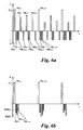
- locating step e) comprises calculating a threshold value for the received signal strength in dependence on the determined radio property, the first transmission power and the predetermined range, comparing the measured received signal strength of the first response with the calculated threshold value, and if the threshold is exceeded, locating the onboard unit as being within the predetermined range. Since here the radio beacon of the beacon only has to measure the received signal strength of the first response and thereby can locate the onboard unit without sending a second request or without receiving a second response of the onboard unit, first requests can be sent quickly in succession, without overloading the radio channel between OBU and radio beacon.
- the observed radio property is a measure of the transmission power capability of the radio transceiver of the onboard unit.
- the distance of the radio beacon to that on-board unit that has answered the request is so easy to determine based on the known transmission power of the radio beacon.
- the identifier is, as already indicated, merely a type identifier of the radio transceiver, ie no unique identifier for each individual OBU, but only one identifier Type (class) of the OBU identifying identifier.
- Direct assignment of OBU type to radio property is thus possible and the database can be so compact be kept as possible, as the required memory space - compared to a possible direct allocation between individual OBU identifiers and radio characteristics - significantly reduced.
- each of the second requests is addressed to a respective one of the OBU identifiers stored in the presence list. This leads to a time saving since all second answers are received and only then assigned to an OBU identifier, if the addressing does not already take place in the second request.
- the invention provides a radio beacon for locating an on-board unit having the features of claim 9.
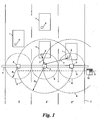
- Fig. 1 There are several vehicles 1 on a lane 2 with different lanes 3, 3 ', 3 ".
- a gantry 4 spans the lane 2 and carries a plurality of radio beacons 5, which are each assigned to a lane 3, 3', 3", for passing vehicles localize (localize) to this lane.
- the localization can be used, for example, for a direction-dependent toll collection, for example in "single lanes” with different directions, or for a lane-dependent toll collection, eg in HOV (high occupancy vehicle) lanes, HOT (high occupancy toll) lanes or the like ,
- each radio beacon 5 in its radio coverage area 6 can perform radio communications 7 with onboard units (OBUs) 8, which are each carried by a vehicle 1.
- the radio coverage area 6 of each beacon 5 is adjustable in size, eg, by adjusting its transmit power (transmit power) and / or receive sensitivity, as discussed in more detail below, as shown by the different radii R 1 and R 2 , for example, the radio coverage area 6 exactly to that lane 3, 3 ', 3 "to which the respective radio beacon 5 is assigned, in the case optimally adapted to the lane width and OBU (here: R 1 ) shows successful radio communication 7 between radio beacon 5 and OBU 8 indicates that the OBU 8 is located on this traffic lane 3, 3 ', 3 ", ie the OBU 8 (and therefore the vehicle 1) is located in the mismatch case when the transmission power and / receive sensitivity of a beacon 5 is too high, false radio communications 7 may occur with OBUs 8 on side lanes ("cross-talk") as shown in right radio communication 7 resulting in a
- the radio beacons 5, OBUs 8 and radio communications 7 between them may be designed according to any radio standard known in the art, eg DSRC (Dedicated Short Range Communication, in particular CEN-DSRC), WAVE (Wireless Access for Vehicle Environment), WLAN (Wireless Local Area Network, in particular IEEE 802.11p, ITS G5 and compatible standards), RFID (radio Frequency Identification, in particular ISO 18000-63 and compatible standards), WiFi ®, Bluetooth ® or the like.
- DSRC Dedicated Short Range Communication, in particular CEN-DSRC
- WAVE Wireless Access for Vehicle Environment
- WLAN Wireless Local Area Network, in particular IEEE 802.11p, ITS G5 and compatible standards
- RFID radio Frequency Identification, in particular ISO 18000-63 and compatible standards
- WiFi ® Wireless Fidelity
- the OBUs can be both of an "active” type, ie with a self-sufficient energy supply, as well as of a “passive” type, ie in the form of transponder chips, particularly preferably RFID chips ("tags"), which generate their energy from the radio field an appealing radio beacon 5 (which is then executed for example in the form of an RFID reader) refer.
- Each successful radio communication 7 usually comprises one or more exchanges (exchanges) of data packets via the radio interface in the form of a request and an associated response.
- the radio communications 7 can serve - in addition to the localization mentioned - various other (main) purposes, such as the identification of passing OBUs 8, the settlement of tolls or road tolls, the supply of OBUs 8 or vehicles 1 with information, etc., these functions are not considered further for the localization described here.
- the radio beacons 5 can be connected via a data connection 9 to a local computer 10 and / or a control center (not shown).
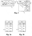
- each on-board unit 8 has a memory 11 and a radio transceiver 12, which are connected via a processor 13.
- the memory 11 includes at least one unique identifier TID of the OBU 8 ("Tag ID” or "OBU identifier") and a type of the OBU 8 or its radio transceiver 12 indicative identifier TP ("type identifier").
- the type identifier TP can also be a part of the OBU identifier TID, ie specify a subrange of the OBU identifier TID of its type TP, as defined, for example, in the standard ISO-18000-63.
- each radio beacon 5 comprises at least one radio transceiver 14, which can communicate with the radio transceiver 12 of an OBU 8, and a connected processor 15.
- the processor is connected to a memory 16, which has a database 17 contains a list TPL of possible type identifiers TP ("type list") of OBUs 8.
- the memory 16 may have a memory area 18 with a list PRL ("presence list") of the respective OBUs 8 currently present in the radio coverage area 6 of the radio beacon 5, the purpose of which will be explained below.
- the database 17 with the type list TPL and the area 18 with the presence list PRL can also be arranged in separate memories, for example via the data connection 9 in FIG local computer 10 and / or a remote center (not shown).
- a beacon 5 for locating an OBU 8 on a lane 3, 3 ', 3 will now be described with reference to FIGS Fig. 3 to 6 explained in more detail, wherein the Fig. 3a . 4a . 5a and 6a a first embodiment and the Fig. 3b . 4b . 5b and 6b show a second embodiment of the method, which can also be combined as desired.
- a first request rq 1 with a first "maximum” transmission power P mx which is at least so large that even those OBUs 8i, which is within the desired localization area 6 furthest from the radio beacon are remote and have a radio transceiver 12i with the lowest receiving sensitivity sens i all possible reception sensitivities sens k of possible OBU types TP k , ie the "worst listen", the first request rq 1 (P mx ) can still receive and process.
- a first response rsp 1, i is obtained from each OBU 8 i currently located in the radio coverage area 6.
- the answer rsp 1, i of each OBU 8 i contains at least the type identifier TP i of the OBU 8 i , preferably also the OBU identifier TID i of the OBU 8 i .
- the latter embodiment of the method in which the OBU identifiers TID i are also received and processed, is able to locate a plurality of OBUs 8 i located simultaneously in the radio coverage area 6 of the radio beacon 5;
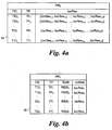
- the presence list PRL in the memory 18 is updated in a step 21 with each receipt of a first answer rsp 1, i , ie the OBU identities TID i of the present OBUs 8 i are entered there ( Fig. 4a, 4b )
- the method should only be suitable for one OBU 8 i in the radio coverage area 6 and no further evaluations are required, the reception of the OBU identifier TID i is unnecessary and the guidance of a presence list PRL in step 21 is omitted.
- an associated radio property of the transceiver 12 i of the respective OBU 8 i is determined from the database 17, more precisely from the type list TPL, to the (or each) just received type identifier TP i .
- this radio property is the receiving sensitivity sens i of the transceiver 12 i .
- a corresponding type list TPL with possible type identifiers TP k of OBUs and their associated receiving sensitivities sens k is stored in the database 17 (FIG. Fig. 3a ).
- the reception sensitivities sens k can be determined, for example, by a one-time measurement of an OBU of the respective type TP k , for example when it comes onto the market or occurs for the first time in the system.
- the reception sensitivity sens k is, for example, a measure that indicates the power with which a signal, such as a request rq 1 from the beacon 5, just has to be received in the onboard unit 2 in order to be processed by it.
- the second transmission power P lo, i calculated individually for the OBU 8 i is then used in a step 24 for a new ("second") request rq 2 of the same OBU 8 i . If, in a second step, a ("second") answer rsp 2 , i from this same OBU 8 i is obtained (branch “y" of the branch 26) in response to this second request rq 2 (P lo, i ), this means that the O-BUi is located in the desired localization area, here for example on the lane 3 '.
- the localization result locRes i, n may be, for example, as a binary value, for example "1" for a successful ("positive") localization (branch “y” of the comparison 26) or "0" for an unsuccessful ("negative") or " Non-localization "(branch” n "of comparison 26).
- the second request rq 2 (P lo, i ) can be sent to the respective OBU identifier in step 24 TID i are addressed (rq 2, i), that is, it can request rq I second are sent in step 24.
- the second responses rsp 2, i obtained with a non-specific (unaddressed) second request rq 2 with OBU identities TID i against the OBU identifier TID i of the first responses rsp 1, i can be checked for assignment of the first and second responses rsp 1, i and rsp 2, i for an OBU 8 i .
- this ratio or the definition of the threshold value can also be adapted to the type identifier TP i , whereby, for example, a quality "worse” OBUs can be assigned a different threshold than OBUs of "higher” quality.
- the threshold may be both absolute, eg, a predetermined minimum number of positive localization results ("y"), or relative, eg, a predetermined percentage of positive localization results ("y") of all localization results ("y” and "n”).
- FIGS Fig. 5b and 6b A second embodiment of the discussed method will now be described with reference to FIGS Fig. 5b and 6b with reference to the list variants of Fig. 3b and 4b described, for simplicity, only the differences from the first embodiment will be discussed.
- Fig. 5b When receiving the first responses rsp 1, i, the received signal strength RSSI i of the respective response rsp 1, i in the radio beacon 5 is also measured in step 20.
- the received signal strength RSSI i can be stored for example in the presence list PRL for further processing ( Fig. 4b ).
- a transmission capacity cg i (“conversion gain”) is then determined from the database 17, more precisely the type list TPL, as the radio property of the OBU 8 i to the received type identifier TP i .
- the transmission power cg i is, for example, a measure which indicates with which absolute transmission power a response rsp 1, i is emitted by the radio transceiver 12 i of an OBU 8 i active type or by what relative proportion of (previously received) transmission power a radio transceiver 12 i of an OBU 8 i passive type in response (rsp 1, i to an incoming request rq 1 can reflect.
- the transmission power capacities cg k of all possible type identifiers TP k of OBUs 8 k can be found, for example, in an earlier (in Fig. 5b not shown) step by a one-time measurement of an OBU of the respective type TP k , when this comes for example on the market or the first time in the system, determined and stored in the type list TPL of the database 17.
- the OBU 8 i is located and the deletion result locRes i, n can now be recreated and optionally stored (step 27) Loop 28 for several passes N, as before for Fig. 5a described.
- the localization result locRes i, n can again be referred to as a binary value, for example "1" for a successful (positive) localization (branch “y” of the comparison 26) or "0” for an unsuccessful (negative) or non-localization ( Branch “n” of comparison 26).
- a localization result locRes i, n as a quantitative measure of the localization, eg the measured received signal strength RSSI i of the respective first response rsp 1, i of the OBU 8 i .
- radio characteristics receiving sensitivity sens k and transmission power cg k of OBUs 8 k stored in the database 17 and be used for the localization of an OBU 8 i on the desired area 6.
Claims (12)
- Procédé pour localiser une unité embarquée (8), qui a un émetteur-récepteur radio (12) et une identification (TP), sur une zone prédéfinie (6) autour d'une balise radio (5), comprenant :a) le stockage de l'identification (TP) de l'unité embarquée (8) et d'une caractéristique radio associée (sens, cg) de son émetteur-récepteur radio (12) dans une banque de données (17) ;b) l'émission d'une première requête (rq1) avec une première puissance d'émission (Pmx) à partir de la balise radio (5) ;c) la réception, au niveau de la balise radio (5), d'une première réponse (rsp1), laquelle contient l'identification (TP) et une identification OBU unique (TID) d'une unité embarquée (8), et le stockage de l'identification OBU (TID) dans une liste de présence (PRL) ;d) la détermination de la caractéristique radio (sens, cg) de l'émetteur-récepteur (12) de l'unité embarquée (8) associée à l'identification reçue (TP) à partir de la banque de données (17) ; ete) la localisation de l'unité embarquée (8) en employant la caractéristique radio (sens, cg) déterminée dans la zone prédéfinie (6) ;dans lequel :les étapes b) à e) sont répétées pour au moins un autre passage après un premier passage,pour chaque passage des étapes b) à e) concernant une identification OBU (TID), chaque fois, un résultat de localisation (loc-Res) est mémorisé dans la liste de présence (PRL) par rapport à cette identification OBU (TID), etla localisation de l'unité embarquée (8) de cette identification OBU (TID) est vérifiée, lorsque le nombre de résultats de localisation (loc-Res) positifs mémorisés pour cette identification OBU (TID) dépasse une valeur de seuil.
- Procédé selon la revendication 1, caractérisé en ce que la localisation de l'étape e) comprend :le calcul d'une deuxième puissance d'émission (Plo) en fonction de la caractéristique radio (sens) déterminée et de la zone prédéfinie (6),l'émission d'une deuxième requête (rq2) avec la deuxième puissance d'émission (P1o) calculée par la balise radio (5),et, lorsqu'une deuxième réponse (rsp2) de la même unité embarquée (8) est réceptionnée suite à la deuxième requête (rq2), la localisation de cette unité embarquée (8) comme se situant dans la zone prédéfinie (6).
- Procédé selon la revendication 2, caractérisé en ce que ladite caractéristique radio est une sensibilité de réception (sens) de l'émetteur-récepteur radio (12) de l'unité embarquée (8).
- Procédé selon la revendication 1, caractérisé en ce que la localisation de l'étape e) comprend :le calcul d'une valeur de seuil (RSSIth), pour la puissance du signal de réception (RSSI) en fonction de la caractéristique radio (cg) déterminée, de la première puissance d'émission (Pmx) et de la zone prédéfinie (6),la comparaison de la puissance du signal de réception mesurée (RSSI) de la première réponse (rsp1) avec la valeur de seuil (RSSIth) calculée,et, en cas de dépassement de la valeur de seuil, la localisation de l'unité embarquée (8) comme se situant dans la zone prédéfinie (6).
- Procédé selon la revendication 4, caractérisé en ce que ladite caractéristique radio est une mesure de la capacité de puissance de l'émission (cg) de l'émetteur-récepteur radio (12) de l'unité embarquée (8).
- Procédé selon l'une des revendications 1 à 5, caractérisé en ce que ladite identification (TP) est une identification de type de l'émetteur-récepteur radio (12).
- Procédé selon l'une des revendications 1 à 6, caractérisé en ce que, lors de plusieurs premières réponses (rsp1) reçues pour une première requête (rq1), toutes les identifications OBU (TID) contenues dans ces réponses sont mémorisées dans la liste de présence (PRL), et
que les étapes d) et e) sont exécutées pour chacune des identifications OBU (TID) mémorisées dans la liste de présence (PRL). - Procédé selon la revendication 7 en liaison avec la revendication 2 ou 3, caractérisé en ce que chacune des deuxièmes requêtes (rq2) est adressée chaque fois à une des identifications OBU (TID) mémorisée dans la liste de présence (PRL).
- Balise radio pour la localisation d'une unité embarquée (8), qui a un émetteur-récepteur radio (12) et une identification (TP), sur une zone prédéfinie (6) autour de la balise radio (5), avec :une mémoire (16) ;un émetteur-récepteur radio (14) ; etun processeur (15) étant en communication avec la mémoire (16) et l'émetteur-récepteur (14) ;dans lequel le processeur (15) est conçu poura) stocker l'identification (TP) de l'unité embarquée (8) et une caractéristique radio (sens, cg) associée de son émetteur-récepteur radio (12) dans la mémoire (16),b) émettre une première requête (rq1) avec une première puissance d'émission (Pmx) par l'émetteur-récepteur radio (14),c) recevoir une première réponse (rsp1), laquelle contient l'identification (TP) et une identification OBU (TID) unique, par l'intermédiaire de l'émetteur-récepteur radio (14) provenant d'une unité embarquée (8) et mémoriser l'identification OBU (TID) dans une liste de présence,d) déterminer la caractéristique radio (sens, cg) de l'émetteur-récepteur (12) de l'unité embarquée (8) associée à l'identification (TP) réceptionnée à partir de la mémoire (16), ete) localiser l'unité embarquée (8) dans la zone prédéfinie (16) moyennant l'utilisation de la caractéristique radio (sens, cg) déterminée, etdans lequel le processeur est en outre conçu pourrépéter les étapes b) à e) après un premier passage pour au moins un nouveau passage,mémoriser, pour chaque passage des étapes b) à e) concernant une identification OBU (TID), chaque fois un résultat de localisation (loc-Res) dans la liste de présence (PRL) par rapport à cette identification OBU (TID), etvérifier la localisation de l'unité embarquée (8) de cette identification OBU (TID) lorsque le nombre des résultats de localisation (loc-Res) positifs mémorisés pour cette identification OBU (TID) dépasse une valeur de seuil.
- Balise radio selon la revendication 9, caractérisé en ce
que ladite caractéristique radio est une mesure pour la sensibilité de réception (sens) de l'émetteur-récepteur radio (12) de l'unité embarquée (8), et
que le processeur (15) est conçu pour, dans ladite localisation,- calculer une deuxième puissance d'émission (P1o) en fonction de la caractéristique radio (sens) déterminée et de la zone prédéfinie (6),- émettre une deuxième requête (rq2) avec la deuxième puissance d'émission (Plo) calculée par l'intermédiaire de l'émetteur-récepteur radio (14), et- lorsqu'une deuxième réponse (rsp2) de la même unité embarquée (8) est réceptionnée suite à la deuxième requête (rq2), localiser cette unité embarquée (8) comme se situant dans la zone prédéfinie (6). - Balise radio selon la revendication 9, caractérisé en ce
que ladite caractéristique radio est une mesure de la capacité de puissance d'émission (cg) de l'émetteur-récepteur radio (12) de l'unité embarquée (8), et
que le processeur (15) est conçu pour, dans ladite localisation,- calculer une valeur de seuil (RSSIth) pour la puissance du signal de réception (RSSI) en fonction de la caractéristique radio (cg) déterminée, de la première puissance d'émission (Pmx) et de la zone prédéfinie (6),- comparer la puissance du signal de réception (RSSI) mesurée de la première réponse (rsp1) avec la valeur de seuil (RSSIth) calculée, et- en cas de dépassement de la valeur de seuil (RSSIth), localiser l'unité embarquée (8) comme se situant dans la zone prédéfinie (6). - Balise radio selon l'une des revendications 9 à 11, caractérisé en ce que ladite identification (TP) est une identification de type de l'émetteur-récepteur radio (12).
Priority Applications (10)
| Application Number | Priority Date | Filing Date | Title |
|---|---|---|---|
| ES13181570.6T ES2588590T3 (es) | 2013-08-23 | 2013-08-23 | Procedimiento y radiobaliza para la localización de una unidad de a bordo |
| EP13181570.6A EP2840554B1 (fr) | 2013-08-23 | 2013-08-23 | Procédé et capteur radio pour la localisation d'une unité embarquée |
| DK13181570.6T DK2840554T3 (en) | 2013-08-23 | 2013-08-23 | METHOD AND RADIO FIRE FOR LOCATION OF AN ONBOARD DEVICE |
| SI201330278A SI2840554T1 (sl) | 2013-08-23 | 2013-08-23 | Postopek in radijska boja za lokaliziranje enote na krovu vozila |
| PT131815706T PT2840554T (pt) | 2013-08-23 | 2013-08-23 | Método e sinal de radio para localizar uma unidade embarcada |
| PL13181570.6T PL2840554T3 (pl) | 2013-08-23 | 2013-08-23 | Sposób oraz radiolatarnia do lokalizacji jednostki pokładowej |
| CA2855668A CA2855668C (fr) | 2013-08-23 | 2014-07-02 | Procede et radiophare de localisation d'un mobimetre |
| US14/463,407 US9408020B2 (en) | 2013-08-23 | 2014-08-19 | Method and radio beacon for localising an on-board unit |
| MX2014010124A MX340338B (es) | 2013-08-23 | 2014-08-22 | Metodo y radiofaro para localizar una unidad de a bordo. |
| BR102014020939-5A BR102014020939B1 (pt) | 2013-08-23 | 2014-08-25 | Método e beacon de rádio para localizar uma unidade de bordo |
Applications Claiming Priority (1)
| Application Number | Priority Date | Filing Date | Title |
|---|---|---|---|
| EP13181570.6A EP2840554B1 (fr) | 2013-08-23 | 2013-08-23 | Procédé et capteur radio pour la localisation d'une unité embarquée |
Publications (2)
| Publication Number | Publication Date |
|---|---|
| EP2840554A1 EP2840554A1 (fr) | 2015-02-25 |
| EP2840554B1 true EP2840554B1 (fr) | 2016-06-15 |
Family
ID=49036446
Family Applications (1)
| Application Number | Title | Priority Date | Filing Date |
|---|---|---|---|
| EP13181570.6A Active EP2840554B1 (fr) | 2013-08-23 | 2013-08-23 | Procédé et capteur radio pour la localisation d'une unité embarquée |
Country Status (10)
| Country | Link |
|---|---|
| US (1) | US9408020B2 (fr) |
| EP (1) | EP2840554B1 (fr) |
| BR (1) | BR102014020939B1 (fr) |
| CA (1) | CA2855668C (fr) |
| DK (1) | DK2840554T3 (fr) |
| ES (1) | ES2588590T3 (fr) |
| MX (1) | MX340338B (fr) |
| PL (1) | PL2840554T3 (fr) |
| PT (1) | PT2840554T (fr) |
| SI (1) | SI2840554T1 (fr) |
Families Citing this family (5)
| Publication number | Priority date | Publication date | Assignee | Title |
|---|---|---|---|---|
| FR3021147B1 (fr) * | 2014-05-16 | 2017-12-22 | Thales Sa | Dispositif de controle des donnees portees par un equipement embarque, systeme de collecte de taxe et procede associes |
| EP3131065A1 (fr) * | 2015-08-14 | 2017-02-15 | Skidata Ag | Procede et systeme de controle d'acces |
| KR102084875B1 (ko) * | 2016-02-26 | 2020-03-04 | 미츠비시 쥬고 기카이 시스템 가부시키가이샤 | 요금 수수 시스템 및 건전성 판단 방법 |
| EP3261060B1 (fr) * | 2016-06-24 | 2021-08-04 | Skidata Ag | Procédés de contrôle d'accès dans un système de contrôle d'accès pour personnes ou véhicules automobiles et système de contrôle d'accès |
| SE542649C2 (en) | 2017-06-28 | 2020-06-23 | Tagmaster Ab | Method and system for remotely detecting a vehicle |
Family Cites Families (3)
| Publication number | Priority date | Publication date | Assignee | Title |
|---|---|---|---|---|
| US7385525B2 (en) * | 2005-07-07 | 2008-06-10 | Mark Iv Industries Corporation | Dynamic timing adjustment in an electronic toll collection system |
| US8508341B2 (en) * | 2009-03-20 | 2013-08-13 | Mar IV Industries Corp. | Adaptive communication in an electronic toll collection system |
| JP2011182340A (ja) * | 2010-03-03 | 2011-09-15 | Toshiba Tec Corp | 質問器 |
-
2013
- 2013-08-23 EP EP13181570.6A patent/EP2840554B1/fr active Active
- 2013-08-23 SI SI201330278A patent/SI2840554T1/sl unknown
- 2013-08-23 PT PT131815706T patent/PT2840554T/pt unknown
- 2013-08-23 DK DK13181570.6T patent/DK2840554T3/en active
- 2013-08-23 PL PL13181570.6T patent/PL2840554T3/pl unknown
- 2013-08-23 ES ES13181570.6T patent/ES2588590T3/es active Active
-
2014
- 2014-07-02 CA CA2855668A patent/CA2855668C/fr active Active
- 2014-08-19 US US14/463,407 patent/US9408020B2/en active Active
- 2014-08-22 MX MX2014010124A patent/MX340338B/es active IP Right Grant
- 2014-08-25 BR BR102014020939-5A patent/BR102014020939B1/pt active IP Right Grant
Also Published As
| Publication number | Publication date |
|---|---|
| DK2840554T3 (en) | 2016-09-12 |
| SI2840554T1 (sl) | 2016-10-28 |
| PT2840554T (pt) | 2016-09-01 |
| MX340338B (es) | 2016-07-05 |
| BR102014020939B1 (pt) | 2022-11-29 |
| US9408020B2 (en) | 2016-08-02 |
| MX2014010124A (es) | 2015-05-27 |
| PL2840554T3 (pl) | 2016-12-30 |
| EP2840554A1 (fr) | 2015-02-25 |
| ES2588590T3 (es) | 2016-11-03 |
| US20150056922A1 (en) | 2015-02-26 |
| CA2855668C (fr) | 2021-03-30 |
| CA2855668A1 (fr) | 2015-02-23 |
| BR102014020939A2 (pt) | 2015-09-22 |
Similar Documents
| Publication | Publication Date | Title |
|---|---|---|
| EP2840554B1 (fr) | Procédé et capteur radio pour la localisation d'une unité embarquée | |
| DE102011085185B3 (de) | Verfahren zum Betreiben eines Kommunikationssystems in der drahtlosen Fahrzeug-zu-Umgebung-Kommunikation und Kommunikationssystem | |
| DE20309955U1 (de) | Primärstation, die Strahlenbündelung und -Durchlauf für gemeinsame und reservierte Kanäle einsetzt | |
| DE112017001387B4 (de) | System zur kommunikation zwischen mobilen körpern, steuervorrichtung für das senden im mobilen körper und steuervorrichtung für den empfang im mobilen körper | |
| DE602004006980T2 (de) | Transponderleser mit der Fähigkeit zum lesen von Transpondern mit verschiedenen Zeichengabeprotokollen | |
| DE102017203905A1 (de) | Verfahren zur Organisation der Kommunikation zwischen Mobilfunknetz-Teilnehmerstationen in einer Mobilfunkzelle, sowie Mobilfunknetz-Teilnehmerstation und Mobilfunknetz-Verwaltungseinheit bei der Verwendung des erfindungsgemäßen Verfahrens | |
| EP3580578A1 (fr) | Protection contre une attaque de relais | |
| EP2381731B1 (fr) | Capteur radio pour un système de péage de routes | |
| EP3146355B1 (fr) | Système d'appareils médicaux et procédé pour localiser des appareils médicaux et des unités de commande mobiles de ce système d'appareils médicaux | |
| EP2637143B1 (fr) | Procédé de communication radio entre un capteur radio et une unité embarquée ainsi que capteur radio et unité embarquée associée | |
| EP3633392A1 (fr) | Concept d'analyse d'un système de radiocommunication | |
| EP3357283B1 (fr) | Procédé et dispositif pour améliorer la qualité de signal d'au moins un service de communication dans la zone d'un véhicule | |
| EP3852072B1 (fr) | Procédé de contrôle d'accès pour personnes et véhicules et système de mise en uvre du procédé | |
| DE102007054678B3 (de) | Verfahren zur Erkennung von Störquellen für Automatisierungseinrichtungen und Störquellenerkennungseinheit hierzu | |
| EP2713305A1 (fr) | Procédé et appareil d'écriture/de lecture pour la configuration d'un appareil d'écriture/de lecture dans un agencement RFID | |
| DE102018207658A1 (de) | Verfahren zum Verarbeiten von Sensordaten, Anordnung zur Verarbeitung von Sensordaten, Anordnung zum Verarbeiten einer Anfrage eines Ego-Fahrzeugs für ein weiteres Fahrzeug, Rechner zum Verarbeiten von Sensordaten sowie Rechner zum Verarbeiten einer Anfrage eines Ego-Fahrzeugs für ein weiteres Fahrzeug | |
| EP3685518B1 (fr) | Émetteur-récepteur avec un capteur pour le calcul d'une information de position d'une antenne d'un autre émetteur-récepteur | |
| EP1638036A1 (fr) | RFID lecteur et méthode pour déterminer et ajuster le canal et la puissance d'émission | |
| EP1995987B1 (fr) | Système d'informations multimédia mobile | |
| DE102019128784A1 (de) | Ortsidentifizierung drahtloser Knoten | |
| DE102019002144A1 (de) | Verfahren zum Auswählen einer ersten Übertragungstechnologie oder einer zweiten Übertragungstechnologie in Abhängigkeit einer Anforderung eines aktuellen Anwendungsfalls sowie elektronische Recheneinrichtung | |
| DE102006041668A1 (de) | Verfahren zur Verifikation von Informationen | |
| DE102018102443A1 (de) | System zur Ortung von Inventar | |
| AT521236A1 (de) | Fahrzeuggerät und Verfahren zur Datenkommunikation | |
| DE10344118B4 (de) | Verfahren zur Ermittlung einer geschätzten Menge von Objekten sowie Einrichtung hierzu |
Legal Events
| Date | Code | Title | Description |
|---|---|---|---|
| PUAI | Public reference made under article 153(3) epc to a published international application that has entered the european phase |
Free format text: ORIGINAL CODE: 0009012 |
|
| 17P | Request for examination filed |
Effective date: 20140425 |
|
| AK | Designated contracting states |
Kind code of ref document: A1 Designated state(s): AL AT BE BG CH CY CZ DE DK EE ES FI FR GB GR HR HU IE IS IT LI LT LU LV MC MK MT NL NO PL PT RO RS SE SI SK SM TR |
|
| AX | Request for extension of the european patent |
Extension state: BA ME |
|
| 17Q | First examination report despatched |
Effective date: 20150605 |
|
| GRAP | Despatch of communication of intention to grant a patent |
Free format text: ORIGINAL CODE: EPIDOSNIGR1 |
|
| INTG | Intention to grant announced |
Effective date: 20151117 |
|
| GRAS | Grant fee paid |
Free format text: ORIGINAL CODE: EPIDOSNIGR3 |
|
| GRAJ | Information related to disapproval of communication of intention to grant by the applicant or resumption of examination proceedings by the epo deleted |
Free format text: ORIGINAL CODE: EPIDOSDIGR1 |
|
| GRAP | Despatch of communication of intention to grant a patent |
Free format text: ORIGINAL CODE: EPIDOSNIGR1 |
|
| GRAS | Grant fee paid |
Free format text: ORIGINAL CODE: EPIDOSNIGR3 |
|
| GRAA | (expected) grant |
Free format text: ORIGINAL CODE: 0009210 |
|
| INTG | Intention to grant announced |
Effective date: 20160429 |
|
| AK | Designated contracting states |
Kind code of ref document: B1 Designated state(s): AL AT BE BG CH CY CZ DE DK EE ES FI FR GB GR HR HU IE IS IT LI LT LU LV MC MK MT NL NO PL PT RO RS SE SI SK SM TR |
|
| REG | Reference to a national code |
Ref country code: CH Ref legal event code: EP Ref country code: GB Ref legal event code: FG4D Free format text: NOT ENGLISH |
|
| REG | Reference to a national code |
Ref country code: IE Ref legal event code: FG4D Free format text: LANGUAGE OF EP DOCUMENT: GERMAN |
|
| REG | Reference to a national code |
Ref country code: AT Ref legal event code: REF Ref document number: 806834 Country of ref document: AT Kind code of ref document: T Effective date: 20160715 |
|
| REG | Reference to a national code |
Ref country code: DE Ref legal event code: R096 Ref document number: 502013003389 Country of ref document: DE |
|
| REG | Reference to a national code |
Ref country code: FR Ref legal event code: PLFP Year of fee payment: 4 |
|
| REG | Reference to a national code |
Ref country code: PT Ref legal event code: SC4A Ref document number: 2840554 Country of ref document: PT Date of ref document: 20160901 Kind code of ref document: T Free format text: AVAILABILITY OF NATIONAL TRANSLATION Effective date: 20160825 |
|
| REG | Reference to a national code |
Ref country code: NL Ref legal event code: FP |
|
| REG | Reference to a national code |
Ref country code: DK Ref legal event code: T3 Effective date: 20160908 |
|
| REG | Reference to a national code |
Ref country code: SE Ref legal event code: TRGR |
|
| REG | Reference to a national code |
Ref country code: LT Ref legal event code: MG4D |
|
| PG25 | Lapsed in a contracting state [announced via postgrant information from national office to epo] |
Ref country code: LT Free format text: LAPSE BECAUSE OF FAILURE TO SUBMIT A TRANSLATION OF THE DESCRIPTION OR TO PAY THE FEE WITHIN THE PRESCRIBED TIME-LIMIT Effective date: 20160615 Ref country code: FI Free format text: LAPSE BECAUSE OF FAILURE TO SUBMIT A TRANSLATION OF THE DESCRIPTION OR TO PAY THE FEE WITHIN THE PRESCRIBED TIME-LIMIT Effective date: 20160615 |
|
| REG | Reference to a national code |
Ref country code: ES Ref legal event code: FG2A Ref document number: 2588590 Country of ref document: ES Kind code of ref document: T3 Effective date: 20161103 |
|
| REG | Reference to a national code |
Ref country code: NO Ref legal event code: T2 Effective date: 20160615 |
|
| PG25 | Lapsed in a contracting state [announced via postgrant information from national office to epo] |
Ref country code: LV Free format text: LAPSE BECAUSE OF FAILURE TO SUBMIT A TRANSLATION OF THE DESCRIPTION OR TO PAY THE FEE WITHIN THE PRESCRIBED TIME-LIMIT Effective date: 20160615 Ref country code: HR Free format text: LAPSE BECAUSE OF FAILURE TO SUBMIT A TRANSLATION OF THE DESCRIPTION OR TO PAY THE FEE WITHIN THE PRESCRIBED TIME-LIMIT Effective date: 20160615 Ref country code: GR Free format text: LAPSE BECAUSE OF FAILURE TO SUBMIT A TRANSLATION OF THE DESCRIPTION OR TO PAY THE FEE WITHIN THE PRESCRIBED TIME-LIMIT Effective date: 20160916 Ref country code: RS Free format text: LAPSE BECAUSE OF FAILURE TO SUBMIT A TRANSLATION OF THE DESCRIPTION OR TO PAY THE FEE WITHIN THE PRESCRIBED TIME-LIMIT Effective date: 20160615 |
|
| PG25 | Lapsed in a contracting state [announced via postgrant information from national office to epo] |
Ref country code: BE Free format text: LAPSE BECAUSE OF NON-PAYMENT OF DUE FEES Effective date: 20160831 |
|
| PG25 | Lapsed in a contracting state [announced via postgrant information from national office to epo] |
Ref country code: EE Free format text: LAPSE BECAUSE OF FAILURE TO SUBMIT A TRANSLATION OF THE DESCRIPTION OR TO PAY THE FEE WITHIN THE PRESCRIBED TIME-LIMIT Effective date: 20160615 Ref country code: IS Free format text: LAPSE BECAUSE OF FAILURE TO SUBMIT A TRANSLATION OF THE DESCRIPTION OR TO PAY THE FEE WITHIN THE PRESCRIBED TIME-LIMIT Effective date: 20161015 Ref country code: RO Free format text: LAPSE BECAUSE OF FAILURE TO SUBMIT A TRANSLATION OF THE DESCRIPTION OR TO PAY THE FEE WITHIN THE PRESCRIBED TIME-LIMIT Effective date: 20160615 |
|
| PG25 | Lapsed in a contracting state [announced via postgrant information from national office to epo] |
Ref country code: SM Free format text: LAPSE BECAUSE OF FAILURE TO SUBMIT A TRANSLATION OF THE DESCRIPTION OR TO PAY THE FEE WITHIN THE PRESCRIBED TIME-LIMIT Effective date: 20160615 |
|
| REG | Reference to a national code |
Ref country code: DE Ref legal event code: R097 Ref document number: 502013003389 Country of ref document: DE |
|
| PG25 | Lapsed in a contracting state [announced via postgrant information from national office to epo] |
Ref country code: MC Free format text: LAPSE BECAUSE OF FAILURE TO SUBMIT A TRANSLATION OF THE DESCRIPTION OR TO PAY THE FEE WITHIN THE PRESCRIBED TIME-LIMIT Effective date: 20160615 |
|
| PLBE | No opposition filed within time limit |
Free format text: ORIGINAL CODE: 0009261 |
|
| STAA | Information on the status of an ep patent application or granted ep patent |
Free format text: STATUS: NO OPPOSITION FILED WITHIN TIME LIMIT |
|
| 26N | No opposition filed |
Effective date: 20170316 |
|
| REG | Reference to a national code |
Ref country code: IE Ref legal event code: MM4A |
|
| PG25 | Lapsed in a contracting state [announced via postgrant information from national office to epo] |
Ref country code: IE Free format text: LAPSE BECAUSE OF NON-PAYMENT OF DUE FEES Effective date: 20160823 |
|
| REG | Reference to a national code |
Ref country code: FR Ref legal event code: PLFP Year of fee payment: 5 |
|
| PG25 | Lapsed in a contracting state [announced via postgrant information from national office to epo] |
Ref country code: LU Free format text: LAPSE BECAUSE OF NON-PAYMENT OF DUE FEES Effective date: 20160823 |
|
| PG25 | Lapsed in a contracting state [announced via postgrant information from national office to epo] |
Ref country code: HU Free format text: LAPSE BECAUSE OF FAILURE TO SUBMIT A TRANSLATION OF THE DESCRIPTION OR TO PAY THE FEE WITHIN THE PRESCRIBED TIME-LIMIT; INVALID AB INITIO Effective date: 20130823 |
|
| PG25 | Lapsed in a contracting state [announced via postgrant information from national office to epo] |
Ref country code: MT Free format text: LAPSE BECAUSE OF FAILURE TO SUBMIT A TRANSLATION OF THE DESCRIPTION OR TO PAY THE FEE WITHIN THE PRESCRIBED TIME-LIMIT Effective date: 20160615 Ref country code: CY Free format text: LAPSE BECAUSE OF FAILURE TO SUBMIT A TRANSLATION OF THE DESCRIPTION OR TO PAY THE FEE WITHIN THE PRESCRIBED TIME-LIMIT Effective date: 20160615 Ref country code: MK Free format text: LAPSE BECAUSE OF FAILURE TO SUBMIT A TRANSLATION OF THE DESCRIPTION OR TO PAY THE FEE WITHIN THE PRESCRIBED TIME-LIMIT Effective date: 20160615 |
|
| PG25 | Lapsed in a contracting state [announced via postgrant information from national office to epo] |
Ref country code: BG Free format text: LAPSE BECAUSE OF FAILURE TO SUBMIT A TRANSLATION OF THE DESCRIPTION OR TO PAY THE FEE WITHIN THE PRESCRIBED TIME-LIMIT Effective date: 20160615 |
|
| REG | Reference to a national code |
Ref country code: FR Ref legal event code: PLFP Year of fee payment: 6 |
|
| PG25 | Lapsed in a contracting state [announced via postgrant information from national office to epo] |
Ref country code: AL Free format text: LAPSE BECAUSE OF FAILURE TO SUBMIT A TRANSLATION OF THE DESCRIPTION OR TO PAY THE FEE WITHIN THE PRESCRIBED TIME-LIMIT Effective date: 20160615 |
|
| PGFP | Annual fee paid to national office [announced via postgrant information from national office to epo] |
Ref country code: NL Payment date: 20190821 Year of fee payment: 7 |
|
| PGFP | Annual fee paid to national office [announced via postgrant information from national office to epo] |
Ref country code: SK Payment date: 20190725 Year of fee payment: 7 Ref country code: PT Payment date: 20190719 Year of fee payment: 7 Ref country code: NO Payment date: 20190827 Year of fee payment: 7 Ref country code: CZ Payment date: 20190724 Year of fee payment: 7 Ref country code: IT Payment date: 20190829 Year of fee payment: 7 Ref country code: SI Payment date: 20190719 Year of fee payment: 7 Ref country code: DK Payment date: 20190821 Year of fee payment: 7 |
|
| PGFP | Annual fee paid to national office [announced via postgrant information from national office to epo] |
Ref country code: PL Payment date: 20190802 Year of fee payment: 7 |
|
| PGFP | Annual fee paid to national office [announced via postgrant information from national office to epo] |
Ref country code: GB Payment date: 20190821 Year of fee payment: 7 |
|
| PGFP | Annual fee paid to national office [announced via postgrant information from national office to epo] |
Ref country code: CH Payment date: 20190821 Year of fee payment: 7 |
|
| REG | Reference to a national code |
Ref country code: NO Ref legal event code: MMEP |
|
| REG | Reference to a national code |
Ref country code: DK Ref legal event code: EBP Effective date: 20200831 |
|
| REG | Reference to a national code |
Ref country code: CH Ref legal event code: PL |
|
| REG | Reference to a national code |
Ref country code: NL Ref legal event code: MM Effective date: 20200901 |
|
| GBPC | Gb: european patent ceased through non-payment of renewal fee |
Effective date: 20200823 |
|
| REG | Reference to a national code |
Ref country code: SK Ref legal event code: MM4A Ref document number: E 22058 Country of ref document: SK Effective date: 20200823 |
|
| PG25 | Lapsed in a contracting state [announced via postgrant information from national office to epo] |
Ref country code: CZ Free format text: LAPSE BECAUSE OF NON-PAYMENT OF DUE FEES Effective date: 20200823 Ref country code: CH Free format text: LAPSE BECAUSE OF NON-PAYMENT OF DUE FEES Effective date: 20200831 Ref country code: LI Free format text: LAPSE BECAUSE OF NON-PAYMENT OF DUE FEES Effective date: 20200831 Ref country code: PT Free format text: LAPSE BECAUSE OF NON-PAYMENT OF DUE FEES Effective date: 20210324 Ref country code: NO Free format text: LAPSE BECAUSE OF NON-PAYMENT OF DUE FEES Effective date: 20200831 |
|
| PG25 | Lapsed in a contracting state [announced via postgrant information from national office to epo] |
Ref country code: SK Free format text: LAPSE BECAUSE OF NON-PAYMENT OF DUE FEES Effective date: 20200823 |
|
| PG25 | Lapsed in a contracting state [announced via postgrant information from national office to epo] |
Ref country code: IT Free format text: LAPSE BECAUSE OF NON-PAYMENT OF DUE FEES Effective date: 20200823 |
|
| PG25 | Lapsed in a contracting state [announced via postgrant information from national office to epo] |
Ref country code: SI Free format text: LAPSE BECAUSE OF NON-PAYMENT OF DUE FEES Effective date: 20200824 Ref country code: GB Free format text: LAPSE BECAUSE OF NON-PAYMENT OF DUE FEES Effective date: 20200823 Ref country code: DK Free format text: LAPSE BECAUSE OF NON-PAYMENT OF DUE FEES Effective date: 20200831 |
|
| REG | Reference to a national code |
Ref country code: SI Ref legal event code: KO00 Effective date: 20210812 |
|
| PG25 | Lapsed in a contracting state [announced via postgrant information from national office to epo] |
Ref country code: NL Free format text: LAPSE BECAUSE OF NON-PAYMENT OF DUE FEES Effective date: 20200901 |
|
| PG25 | Lapsed in a contracting state [announced via postgrant information from national office to epo] |
Ref country code: PL Free format text: LAPSE BECAUSE OF NON-PAYMENT OF DUE FEES Effective date: 20200823 |
|
| P01 | Opt-out of the competence of the unified patent court (upc) registered |
Effective date: 20230513 |
|
| PGFP | Annual fee paid to national office [announced via postgrant information from national office to epo] |
Ref country code: TR Payment date: 20230821 Year of fee payment: 11 Ref country code: AT Payment date: 20230822 Year of fee payment: 11 |
|
| PGFP | Annual fee paid to national office [announced via postgrant information from national office to epo] |
Ref country code: SE Payment date: 20230821 Year of fee payment: 11 Ref country code: FR Payment date: 20230824 Year of fee payment: 11 Ref country code: DE Payment date: 20230821 Year of fee payment: 11 |
|
| PGFP | Annual fee paid to national office [announced via postgrant information from national office to epo] |
Ref country code: ES Payment date: 20231027 Year of fee payment: 11 |