EP2840271A2 - Arrangement de palier avec une bague de retenue et méthode de fabrication - Google Patents
Arrangement de palier avec une bague de retenue et méthode de fabrication Download PDFInfo
- Publication number
- EP2840271A2 EP2840271A2 EP14180796.6A EP14180796A EP2840271A2 EP 2840271 A2 EP2840271 A2 EP 2840271A2 EP 14180796 A EP14180796 A EP 14180796A EP 2840271 A2 EP2840271 A2 EP 2840271A2
- Authority
- EP
- European Patent Office
- Prior art keywords
- housing
- outer race
- retaining ring
- radially
- bearing assembly
- Prior art date
- Legal status (The legal status is an assumption and is not a legal conclusion. Google has not performed a legal analysis and makes no representation as to the accuracy of the status listed.)
- Ceased
Links
Images




Classifications
-
- F—MECHANICAL ENGINEERING; LIGHTING; HEATING; WEAPONS; BLASTING
- F16—ENGINEERING ELEMENTS AND UNITS; GENERAL MEASURES FOR PRODUCING AND MAINTAINING EFFECTIVE FUNCTIONING OF MACHINES OR INSTALLATIONS; THERMAL INSULATION IN GENERAL
- F16C—SHAFTS; FLEXIBLE SHAFTS; ELEMENTS OR CRANKSHAFT MECHANISMS; ROTARY BODIES OTHER THAN GEARING ELEMENTS; BEARINGS
- F16C35/00—Rigid support of bearing units; Housings, e.g. caps, covers
- F16C35/04—Rigid support of bearing units; Housings, e.g. caps, covers in the case of ball or roller bearings
- F16C35/06—Mounting or dismounting of ball or roller bearings; Fixing them onto shaft or in housing
- F16C35/07—Fixing them on the shaft or housing with interposition of an element
- F16C35/077—Fixing them on the shaft or housing with interposition of an element between housing and outer race ring
-
- F—MECHANICAL ENGINEERING; LIGHTING; HEATING; WEAPONS; BLASTING
- F16—ENGINEERING ELEMENTS AND UNITS; GENERAL MEASURES FOR PRODUCING AND MAINTAINING EFFECTIVE FUNCTIONING OF MACHINES OR INSTALLATIONS; THERMAL INSULATION IN GENERAL
- F16C—SHAFTS; FLEXIBLE SHAFTS; ELEMENTS OR CRANKSHAFT MECHANISMS; ROTARY BODIES OTHER THAN GEARING ELEMENTS; BEARINGS
- F16C19/00—Bearings with rolling contact, for exclusively rotary movement
- F16C19/22—Bearings with rolling contact, for exclusively rotary movement with bearing rollers essentially of the same size in one or more circular rows, e.g. needle bearings
- F16C19/24—Bearings with rolling contact, for exclusively rotary movement with bearing rollers essentially of the same size in one or more circular rows, e.g. needle bearings for radial load mainly
-
- F—MECHANICAL ENGINEERING; LIGHTING; HEATING; WEAPONS; BLASTING
- F16—ENGINEERING ELEMENTS AND UNITS; GENERAL MEASURES FOR PRODUCING AND MAINTAINING EFFECTIVE FUNCTIONING OF MACHINES OR INSTALLATIONS; THERMAL INSULATION IN GENERAL
- F16C—SHAFTS; FLEXIBLE SHAFTS; ELEMENTS OR CRANKSHAFT MECHANISMS; ROTARY BODIES OTHER THAN GEARING ELEMENTS; BEARINGS
- F16C19/00—Bearings with rolling contact, for exclusively rotary movement
- F16C19/52—Bearings with rolling contact, for exclusively rotary movement with devices affected by abnormal or undesired conditions
- F16C19/525—Bearings with rolling contact, for exclusively rotary movement with devices affected by abnormal or undesired conditions related to temperature and heat, e.g. insulation
-
- F—MECHANICAL ENGINEERING; LIGHTING; HEATING; WEAPONS; BLASTING
- F16—ENGINEERING ELEMENTS AND UNITS; GENERAL MEASURES FOR PRODUCING AND MAINTAINING EFFECTIVE FUNCTIONING OF MACHINES OR INSTALLATIONS; THERMAL INSULATION IN GENERAL
- F16C—SHAFTS; FLEXIBLE SHAFTS; ELEMENTS OR CRANKSHAFT MECHANISMS; ROTARY BODIES OTHER THAN GEARING ELEMENTS; BEARINGS
- F16C25/00—Bearings for exclusively rotary movement adjustable for wear or play
- F16C25/06—Ball or roller bearings
- F16C25/08—Ball or roller bearings self-adjusting
-
- F—MECHANICAL ENGINEERING; LIGHTING; HEATING; WEAPONS; BLASTING
- F16—ENGINEERING ELEMENTS AND UNITS; GENERAL MEASURES FOR PRODUCING AND MAINTAINING EFFECTIVE FUNCTIONING OF MACHINES OR INSTALLATIONS; THERMAL INSULATION IN GENERAL
- F16C—SHAFTS; FLEXIBLE SHAFTS; ELEMENTS OR CRANKSHAFT MECHANISMS; ROTARY BODIES OTHER THAN GEARING ELEMENTS; BEARINGS
- F16C33/00—Parts of bearings; Special methods for making bearings or parts thereof
- F16C33/30—Parts of ball or roller bearings
- F16C33/58—Raceways; Race rings
-
- F—MECHANICAL ENGINEERING; LIGHTING; HEATING; WEAPONS; BLASTING
- F16—ENGINEERING ELEMENTS AND UNITS; GENERAL MEASURES FOR PRODUCING AND MAINTAINING EFFECTIVE FUNCTIONING OF MACHINES OR INSTALLATIONS; THERMAL INSULATION IN GENERAL
- F16C—SHAFTS; FLEXIBLE SHAFTS; ELEMENTS OR CRANKSHAFT MECHANISMS; ROTARY BODIES OTHER THAN GEARING ELEMENTS; BEARINGS
- F16C33/00—Parts of bearings; Special methods for making bearings or parts thereof
- F16C33/30—Parts of ball or roller bearings
- F16C33/58—Raceways; Race rings
- F16C33/583—Details of specific parts of races
- F16C33/586—Details of specific parts of races outside the space between the races, e.g. end faces or bore of inner ring
-
- F—MECHANICAL ENGINEERING; LIGHTING; HEATING; WEAPONS; BLASTING
- F16—ENGINEERING ELEMENTS AND UNITS; GENERAL MEASURES FOR PRODUCING AND MAINTAINING EFFECTIVE FUNCTIONING OF MACHINES OR INSTALLATIONS; THERMAL INSULATION IN GENERAL
- F16C—SHAFTS; FLEXIBLE SHAFTS; ELEMENTS OR CRANKSHAFT MECHANISMS; ROTARY BODIES OTHER THAN GEARING ELEMENTS; BEARINGS
- F16C33/00—Parts of bearings; Special methods for making bearings or parts thereof
- F16C33/30—Parts of ball or roller bearings
- F16C33/58—Raceways; Race rings
- F16C33/60—Raceways; Race rings divided or split, e.g. comprising two juxtaposed rings
-
- F—MECHANICAL ENGINEERING; LIGHTING; HEATING; WEAPONS; BLASTING
- F16—ENGINEERING ELEMENTS AND UNITS; GENERAL MEASURES FOR PRODUCING AND MAINTAINING EFFECTIVE FUNCTIONING OF MACHINES OR INSTALLATIONS; THERMAL INSULATION IN GENERAL
- F16C—SHAFTS; FLEXIBLE SHAFTS; ELEMENTS OR CRANKSHAFT MECHANISMS; ROTARY BODIES OTHER THAN GEARING ELEMENTS; BEARINGS
- F16C35/00—Rigid support of bearing units; Housings, e.g. caps, covers
- F16C35/04—Rigid support of bearing units; Housings, e.g. caps, covers in the case of ball or roller bearings
- F16C35/06—Mounting or dismounting of ball or roller bearings; Fixing them onto shaft or in housing
- F16C35/067—Fixing them in a housing
-
- F—MECHANICAL ENGINEERING; LIGHTING; HEATING; WEAPONS; BLASTING
- F16—ENGINEERING ELEMENTS AND UNITS; GENERAL MEASURES FOR PRODUCING AND MAINTAINING EFFECTIVE FUNCTIONING OF MACHINES OR INSTALLATIONS; THERMAL INSULATION IN GENERAL
- F16C—SHAFTS; FLEXIBLE SHAFTS; ELEMENTS OR CRANKSHAFT MECHANISMS; ROTARY BODIES OTHER THAN GEARING ELEMENTS; BEARINGS
- F16C43/00—Assembling bearings
- F16C43/04—Assembling rolling-contact bearings
-
- F—MECHANICAL ENGINEERING; LIGHTING; HEATING; WEAPONS; BLASTING
- F16—ENGINEERING ELEMENTS AND UNITS; GENERAL MEASURES FOR PRODUCING AND MAINTAINING EFFECTIVE FUNCTIONING OF MACHINES OR INSTALLATIONS; THERMAL INSULATION IN GENERAL
- F16C—SHAFTS; FLEXIBLE SHAFTS; ELEMENTS OR CRANKSHAFT MECHANISMS; ROTARY BODIES OTHER THAN GEARING ELEMENTS; BEARINGS
- F16C19/00—Bearings with rolling contact, for exclusively rotary movement
- F16C19/02—Bearings with rolling contact, for exclusively rotary movement with bearing balls essentially of the same size in one or more circular rows
- F16C19/04—Bearings with rolling contact, for exclusively rotary movement with bearing balls essentially of the same size in one or more circular rows for radial load mainly
- F16C19/06—Bearings with rolling contact, for exclusively rotary movement with bearing balls essentially of the same size in one or more circular rows for radial load mainly with a single row or balls
-
- F—MECHANICAL ENGINEERING; LIGHTING; HEATING; WEAPONS; BLASTING
- F16—ENGINEERING ELEMENTS AND UNITS; GENERAL MEASURES FOR PRODUCING AND MAINTAINING EFFECTIVE FUNCTIONING OF MACHINES OR INSTALLATIONS; THERMAL INSULATION IN GENERAL
- F16C—SHAFTS; FLEXIBLE SHAFTS; ELEMENTS OR CRANKSHAFT MECHANISMS; ROTARY BODIES OTHER THAN GEARING ELEMENTS; BEARINGS
- F16C2202/00—Solid materials defined by their properties
- F16C2202/20—Thermal properties
- F16C2202/22—Coefficient of expansion
-
- F—MECHANICAL ENGINEERING; LIGHTING; HEATING; WEAPONS; BLASTING
- F16—ENGINEERING ELEMENTS AND UNITS; GENERAL MEASURES FOR PRODUCING AND MAINTAINING EFFECTIVE FUNCTIONING OF MACHINES OR INSTALLATIONS; THERMAL INSULATION IN GENERAL
- F16C—SHAFTS; FLEXIBLE SHAFTS; ELEMENTS OR CRANKSHAFT MECHANISMS; ROTARY BODIES OTHER THAN GEARING ELEMENTS; BEARINGS
- F16C2226/00—Joining parts; Fastening; Assembling or mounting parts
- F16C2226/50—Positive connections
- F16C2226/70—Positive connections with complementary interlocking parts
-
- F—MECHANICAL ENGINEERING; LIGHTING; HEATING; WEAPONS; BLASTING
- F16—ENGINEERING ELEMENTS AND UNITS; GENERAL MEASURES FOR PRODUCING AND MAINTAINING EFFECTIVE FUNCTIONING OF MACHINES OR INSTALLATIONS; THERMAL INSULATION IN GENERAL
- F16C—SHAFTS; FLEXIBLE SHAFTS; ELEMENTS OR CRANKSHAFT MECHANISMS; ROTARY BODIES OTHER THAN GEARING ELEMENTS; BEARINGS
- F16C2360/00—Engines or pumps
- F16C2360/22—Internal combustion engines
-
- Y—GENERAL TAGGING OF NEW TECHNOLOGICAL DEVELOPMENTS; GENERAL TAGGING OF CROSS-SECTIONAL TECHNOLOGIES SPANNING OVER SEVERAL SECTIONS OF THE IPC; TECHNICAL SUBJECTS COVERED BY FORMER USPC CROSS-REFERENCE ART COLLECTIONS [XRACs] AND DIGESTS
- Y10—TECHNICAL SUBJECTS COVERED BY FORMER USPC
- Y10T—TECHNICAL SUBJECTS COVERED BY FORMER US CLASSIFICATION
- Y10T29/00—Metal working
- Y10T29/49—Method of mechanical manufacture
- Y10T29/49636—Process for making bearing or component thereof
- Y10T29/49643—Rotary bearing
- Y10T29/49679—Anti-friction bearing or component thereof
- Y10T29/49689—Race making
Definitions
- the present disclosure relates to a bearing assembly having a retaining ring disposed in respective grooves in a housing and an outer race for the bearing assembly adapted to fix a position of the outer race with respect to the housing.
- the thermal expansion coefficient of the retaining ring is at least equal to the thermal expansion coefficient of the housing to ensure that the retaining ring remains in the groove in the housing when the bearing assembly is exposed to elevated temperatures.
- Bearing arrangements for example for internal combustion engines, are known to comprise a housing made of a first material and an outer race radially enclosed by the housing and made of a second material.
- the outer race must be axially fixed with respect to the housing.
- the first material such as aluminum or an aluminum alloy
- the second material such as steel
- the housing expands more radially outward than the outer race, thereby increasing contact between the housing and the housing outer race is interrupted, which prevents axial fixation of the outer race with respect to the housing.
- Patent Application Publication 2006/0160651 discloses the use of an intermediate liner in engagement with an axial surface of a bearing race to compensate for thermal expansion in a differential gear by axial expansion to compress the bearing race.
- the U.S. Patent 8,286,533 discloses the use of retaining clips which greatly increase the complexity of the bearing assembly and also increase the cost and dimensions of the bearing assembly.
- the U.S. Patent 4,549,823 discloses the use of an elastomeric ring between a housing and an outer race of a bearing assembly.
- a bearing assembly which includes a housing having a first circumferentially disposed groove, a bearing having an outer race with a second circumferentially disposed groove, and a retaining ring disposed circumferentially within the first and second circumferences Groove is arranged.
- a method of retaining a bearing comprising the steps of: disposing a first portion of an annular retaining ring within a first circumferentially disposed outer race of the bearing, installing a housing radially about the outer race so that Housing contacts the outer race, arranging a second portion of the retaining ring within a second circumferentially arranged groove for the housing, bring respective temperatures of the housing and the outer race to a first level, fixing axial and radial positions of the outer race with respect to the housing a contact between the outer race and the housing, increasing the respective temperatures of the housing and the outer race to a second level which is higher than the first level, generating a radial clearance between the housing and the outer en race and fixing the axial and radial positions of the axial and radial positions with the retaining ring.
- a bearing assembly which includes a bearing having an annular outer race constructed of a first material having a first coefficient of thermal expansion and having a radially outer peripheral surface and a first circumferentially disposed groove in the radially outer Peripheral surface, an annular housing, which is arranged radially around the bearing, is constructed of a second material having a second coefficient of thermal expansion, which is greater than the first coefficient of thermal expansion, and having a radially inner peripheral surface and a second circumferentially arranged groove in the radially inner peripheral surface and an annular retaining ring, comprising: a first portion disposed within the first circumferentially disposed groove and a second portion circumferentially disposed within the second en groove is arranged.
- FIG. 12 is a perspective view of a cylindrical coordinate system 80 illustrating the spatial terminology used in the present disclosure.
- the present disclosure will be described, at least in part, in the context of a cylindrical coordinate system.
- the system 80 has a longitudinal axis 81 which is used as a reference for the following directional terms and spatial terms.
- the adjectives "axial”, “radial” and “circumferential” refer to an orientation parallel to the axis 81, to the radius 82 (which is orthogonal to the axis 81) and to the circumference 83, respectively.
- the adjectives "axial”, “radial” and “circumferential” also refers to an orientation parallel to respective levels. To explain the arrangement of the various levels, objects 84, 85 and 86 are used.
- the surface 87 of the object 84 forms an axial plane. That is, the axis 81 forms a line along the surface.
- the surface 88 of the object 85 forms a radial plane. That is, the radius 82 forms a line along the surface.
- the surface 89 of the object 86 forms a circumferential plane. That is, the circumference 83 forms a line along the surface.
- a rotation refers to the axis 81.
- the adverbs "axial”, “radial” and “circumferential” refer to an orientation parallel to the axis 81, the radius 82 and the circumference 83, respectively.
- the adverbs "axial”, “radial” and “circumferential” also refer to one Orientation parallel to respective levels.
- FIG. 1B is a perspective view of an object 90 in the cylindrical coordinate system 80 from Figure 1A which illustrates the spatial terminology used in the present disclosure.
- the cylindrical object 90 represents a cylindrical object in a cylindrical coordinate system and is not intended to limit the present disclosure in any way.
- the object 90 has an axial surface 91, a radial surface 92 and a circumferential surface 93.
- the surface 91 is part of an axial plane
- the surface 92 is part of a radial plane
- the surface 93 is a peripheral surface.
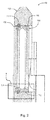
- FIG. 2 is a partial sectional view of a bearing assembly 100 with a retaining ring.
- FIG. 3 is a perspective view of the area 3 in FIG. 2 , The following should be given the Figures 2 and 3 to be viewed as.
- the assembly 100 includes a rotational axis AR, an annular housing 102, an annular outer race 104, and an annular retaining ring 106.
- the housing 102 has a radially inner circumferential surface 108 with a circumferentially arranged groove 110. That is, the groove 110 intersects the surface 108.
- the race 104 has a radially outer peripheral surface 112 with a circumferentially disposed groove 114. That is, the groove 114 intersects the surface 112.
- the ring 106 is disposed in the grooves 110 and 112.
- the radially outermost portion 106A of the ring 106 is disposed in the groove 110, and the radially innermost portion 106B of the ring 106 is disposed in the groove 114.
- the housing 102 is disposed radially around the race 104.
- the retaining ring restricts the outer race axially and / or radially with respect to the housing.
- circumferentially arranged is meant that the respective groove is continuous around the housing or the raceway extends in the above-defined circumferential direction and has a depth in the radial direction as defined above and a width in the axial direction as defined above.
- one or both of the grooves 110 and 114 extend 360 degrees in the circumferential direction.
- one or both of the grooves 110 and 114 extend less than 360 degrees in the circumferential direction.
- the circumferential ends of the groove 110 are separated by a portion of the surface 108.
- the housing 102 is constructed of a material such as aluminum or an aluminum alloy having a certain coefficient of thermal expansion
- the retaining ring 106 is constructed of another material having a coefficient of thermal expansion greater than or equal to the thermal expansion coefficient the housing 102 is.
- the housing 102 and the ring 106 are constructed of the same material.
- the race 104 is constructed of a material, such as steel, having a coefficient of thermal expansion that is less than the respective thermal expansion coefficients of the housing and the ring.
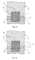
- FIG. 4A is a detailed view of the housing and the outer race FIG. 2 at a low temperature.
- the following should be given the Figures 2 to 4A to be viewed as.
- the outer race 104 is fixed axially and radially with respect to the housing 102 by the contact between the housing 102 and the outer race 104.
- the low temperature may be considered a non-operating temperature for the engine For example, it does not work and is at ambient temperature or the machine has started to work, but has not yet heated up.
- the non-operating temperature may also be defined as a temperature at which the thermal expansion of the housing 102 and the outer race 104 has not occurred or in which the respective thermal expansions of the housing 102 and the outer race 104 are substantially equal.
- FIG. 4B is a detailed view of the housing and the outer race FIG. 2 at a high temperature.
- the housing 102 and the outer race 104 are each at substantially a relatively high temperature, the radial clearance 116 is created between the housing 102 and the outer race 104 (between the surfaces 108 and 112) and the outer race 104 is replaced by the outer race 104 outer race 104 axially and radially fixed with respect to the housing 102.
- the high temperature may be considered as an operating temperature for the engine, for example, where the engine is operating and the internal combustion process has increased the temperature of the housing 102 and outer race 104 well above ambient temperature.
- the operating temperature may also be defined as a temperature at which the thermal expansion of the housing 102 has occurred or occurs at a higher rate than the thermal expansion of the outer race 104.
- the housing 102 expands at a greater rate than the outer race 104, causing the housing 102 to expand Gap 116 is generated. Due to the clearance 116, the above-mentioned compressive engagement or frictional engagement between the housing 102 and the outer race 104 is substantially canceled. Therefore, the engagement between the housing 102 and the outer race 104 is insufficient to retain the outer race 104 with respect to the housing 102 (fixing the axial and radial positions of the outer race 104 with respect to the housing 102). The retaining ring 106, however, remains in contact with the housing 102 and the outer race 104 (disposed in the grooves 108 and 112) to retain the outer race 104 with respect to the housing 102.
- portions 106A and 106B thereof remain in grooves 110 and 114, respectively.
- the portion expands 106A within the groove 114 to increase the contact pressure (compressive pressure or friction pressure) in the axial and / or radial direction between the portion 106B and the race 104, thereby fixing the ring 106 more firmly with respect to the race 104.
- the ring 106 expands radially outward, thereby ensuring that the portion 106A remains disposed in the groove 110.
- the portion 106A expands within the groove 110, thereby increasing the contact pressure between the portion 106B and the housing 102 in axial and / or axial directions radial direction is increased. This increase in contact pressure further facilitates the fixation of the ring 106 with respect to the housing 102 and therefore the fixation of the race 104 with respect to the housing 102.
- FIG. 5 is a schematic front view of the bearing assembly 100 with a retaining ring, wherein a two-part housing is shown.
- the housing 102 has separate sections 102A and 102B which are fixedly connected together by any means known in the art. Sections 102A and 102B facilitate fabrication of assembly 100.
- ring 106 may be made with a discontinuity to allow annulus 106 to expand radially to pass over race 104 and slide into groove 114. The sections 102A and 102B may then be arranged together so that the groove 110 encloses the ring 106.
- FIG. 6 is a partial sectional view of the bearing assembly 100 with a retaining ring.
- the assembly 100 is shown in an example configuration having an inner race 118, a skirt 120, and a roller member 122. It should be noted that the assembly 100 is not made to be used with the configuration FIG. 6 is limited.
Landscapes
- Engineering & Computer Science (AREA)
- General Engineering & Computer Science (AREA)
- Mechanical Engineering (AREA)
- Rolling Contact Bearings (AREA)
- Mounting Of Bearings Or Others (AREA)
Applications Claiming Priority (1)
| Application Number | Priority Date | Filing Date | Title |
|---|---|---|---|
| US201361868892P | 2013-08-22 | 2013-08-22 |
Publications (2)
| Publication Number | Publication Date |
|---|---|
| EP2840271A2 true EP2840271A2 (fr) | 2015-02-25 |
| EP2840271A3 EP2840271A3 (fr) | 2015-05-06 |
Family
ID=51352417
Family Applications (1)
| Application Number | Title | Priority Date | Filing Date |
|---|---|---|---|
| EP14180796.6A Ceased EP2840271A3 (fr) | 2013-08-22 | 2014-08-13 | Arrangement de palier avec une bague de retenue et méthode de fabrication |
Country Status (2)
| Country | Link |
|---|---|
| US (1) | US9518608B2 (fr) |
| EP (1) | EP2840271A3 (fr) |
Families Citing this family (3)
| Publication number | Priority date | Publication date | Assignee | Title |
|---|---|---|---|---|
| JP6550947B2 (ja) * | 2015-06-11 | 2019-07-31 | 株式会社Ihi | 回転機械 |
| US10550893B2 (en) * | 2017-04-19 | 2020-02-04 | Seiko Instruments Inc. | Rolling bearing |
| JP2019049316A (ja) * | 2017-09-11 | 2019-03-28 | スズキ株式会社 | 軸受部構造及びその製造方法 |
Citations (4)
| Publication number | Priority date | Publication date | Assignee | Title |
|---|---|---|---|---|
| US4549823A (en) | 1984-05-29 | 1985-10-29 | Caterpillar Tractor Co. | Bearing race retention device and method |
| US20060160651A1 (en) | 2005-01-20 | 2006-07-20 | Petruska Paul H | Thermally compensating bearing preload arrangement in axle assembly |
| US20090080824A1 (en) | 2004-07-26 | 2009-03-26 | The Timken Company | Bearing having thermal compensating capability |
| US8286533B2 (en) | 2006-12-15 | 2012-10-16 | Robert Bosch Gmbh | Gear housing |
Family Cites Families (31)
| Publication number | Priority date | Publication date | Assignee | Title |
|---|---|---|---|---|
| US119232A (en) * | 1871-09-26 | Improvement in sucker-rods | ||
| US2316498A (en) * | 1941-11-18 | 1943-04-13 | Jr Charles A Biczak | Wheel for roller skates |
| US2607642A (en) * | 1946-10-25 | 1952-08-19 | Bendix Aviat Corp | Antifriction bearing and associated member |
| US2456355A (en) * | 1947-01-13 | 1948-12-14 | Joseph S Aber | Elastic snap ring fastener |
| GB1471254A (en) * | 1973-12-20 | 1977-04-21 | Simon Barron Ltd | Pelletising machines |
| DE2400902C2 (de) | 1974-01-09 | 1982-05-27 | A. Friedr. Flender Gmbh & Co Kg, 4290 Bocholt | Wälzlagereinbau |
| CH592262A5 (fr) * | 1975-07-04 | 1977-10-14 | Bbc Brown Boveri & Cie | |
| DE2603685A1 (de) * | 1976-01-31 | 1977-08-04 | Kugelfischer G Schaefer & Co | Befestigung zweier schraeglager |
| DE2658157A1 (de) * | 1976-12-22 | 1978-06-29 | Zahnradfabrik Friedrichshafen | Axiale fixierung fuer waelzlager |
| US4316678A (en) * | 1979-10-05 | 1982-02-23 | The United States Of America As Represented By The Secretary Of The Army | Means for securing two elements against relative axial movement |
| US4405251A (en) * | 1980-03-06 | 1983-09-20 | Miller Fluid Power Corporation | Retaining ring locking device |
| US4775273A (en) * | 1981-01-23 | 1988-10-04 | Peter Bauer | Bistable shaft retaining element |
| US4511191A (en) * | 1984-02-14 | 1985-04-16 | Koyo Seike Company Limited | Anticreep device for annular member |
| DE3421188A1 (de) * | 1984-06-07 | 1985-12-12 | SKF GmbH, 8720 Schweinfurt | Befestigung eines waelzlagers in einem gehaeuse o.dgl. |
| US5028152A (en) * | 1990-03-21 | 1991-07-02 | The Timken Company | Machine with thermally compensated bearings |
| US5209577A (en) * | 1991-11-13 | 1993-05-11 | Camco International, Inc. | Downhole rotating machine having compliant radial bearings |
| SE0102081L (sv) * | 2001-06-12 | 2002-08-27 | Skf Ab | Monteringsorgan |
| JP4296748B2 (ja) | 2002-03-27 | 2009-07-15 | 株式会社ジェイテクト | 軸受及びその取付構造 |
| JP2005121120A (ja) * | 2003-10-16 | 2005-05-12 | Ntn Corp | 車輪用軸受装置 |
| US7374345B2 (en) * | 2003-10-28 | 2008-05-20 | Fag Kugelfischer Ag | System for securing a roller bearing in axial directions |
| DE102004052105B4 (de) * | 2004-10-26 | 2007-05-03 | Christian Bauer Gmbh + Co. | Radial geschlitzter, elastisch durchmesserveränderbarer Ring, insbesondere Sicherungsring |
| US20080292393A1 (en) * | 2007-05-23 | 2008-11-27 | Toyota Motor Engineering & Manufacturing North America, Inc. | Plastic semi-permanent retainer ring |
| JP2009008202A (ja) | 2007-06-29 | 2009-01-15 | Jtekt Corp | 転がり軸受の固定構造 |
| WO2009123254A1 (fr) * | 2008-04-04 | 2009-10-08 | Ntn株式会社 | Appareil de palier de roue et module d'essieu |
| DE102009017007B4 (de) * | 2009-04-14 | 2016-10-20 | Shaft-Form-Engineering Gmbh | Anbindungssystem und Gleichlaufgelenk |
| US8740467B2 (en) * | 2009-09-21 | 2014-06-03 | Diversified Machine, Inc. | Wheel bearing retainer |
| US9004805B2 (en) * | 2010-11-30 | 2015-04-14 | Bal Seal Engineering, Inc. | Multi-stage engagement assemblies and related methods |
| DE102011004414A1 (de) | 2011-02-18 | 2012-08-23 | Schaeffler Technologies Gmbh & Co. Kg | Verfahren zur Montage von wenigstens einem Thermokompensationselement in vorgespannten Lageranordnungen |
| DE202012008997U1 (de) * | 2012-09-19 | 2014-01-14 | Bümach Engineering International B.V. | Kolbeneinheit eines Arbeitszylinders |
| DE202012008999U1 (de) * | 2012-09-19 | 2014-01-15 | Bümach Engineering International B.V. | Kolbeneinheit eines Arbeitszylinders |
| US9829028B2 (en) * | 2012-11-15 | 2017-11-28 | Bal Seal Engineering, Inc. | Connectors with a pin, a housing, and one or more springs |
-
2014
- 2014-08-13 EP EP14180796.6A patent/EP2840271A3/fr not_active Ceased
- 2014-08-13 US US14/458,786 patent/US9518608B2/en active Active
Patent Citations (5)
| Publication number | Priority date | Publication date | Assignee | Title |
|---|---|---|---|---|
| US4549823A (en) | 1984-05-29 | 1985-10-29 | Caterpillar Tractor Co. | Bearing race retention device and method |
| US20090080824A1 (en) | 2004-07-26 | 2009-03-26 | The Timken Company | Bearing having thermal compensating capability |
| US20060160651A1 (en) | 2005-01-20 | 2006-07-20 | Petruska Paul H | Thermally compensating bearing preload arrangement in axle assembly |
| US8286533B2 (en) | 2006-12-15 | 2012-10-16 | Robert Bosch Gmbh | Gear housing |
| US20120304813A1 (en) | 2006-12-15 | 2012-12-06 | Robert Bosch Gmbh | Gear housing |
Also Published As
| Publication number | Publication date |
|---|---|
| EP2840271A3 (fr) | 2015-05-06 |
| US20150055907A1 (en) | 2015-02-26 |
| US9518608B2 (en) | 2016-12-13 |
Similar Documents
| Publication | Publication Date | Title |
|---|---|---|
| DE112013001763B4 (de) | Kupplungsbaugruppe mit einer Zungen-Niet-Verbindung und Verfahren dafür | |
| DE102015217293A1 (de) | Kraftübertragungswelle und Kardanwelle für ein Fahrzeug | |
| DE112008002351T5 (de) | Lagerungsvorrichtung für Rad | |
| WO2012019585A2 (fr) | Embrayage à friction | |
| DE102009007061A1 (de) | Drehmomentwandler mit Zentrierung und Halterung des turbinenseitigen Lagers am Leitrad | |
| DE112010002239T5 (de) | Lagervorrichtung für ein Fahrzeug | |
| DE102016113220A1 (de) | Kugellager | |
| DE102012022465A1 (de) | Gleitringdichtungsanordnung mit verbesserter Nebendichtung | |
| DE112010002565T5 (de) | Radlager | |
| DE112007000320B4 (de) | Lagervorrichtung für ein Fahrzeugrad | |
| EP2840271A2 (fr) | Arrangement de palier avec une bague de retenue et méthode de fabrication | |
| EP2565478A1 (fr) | Agencement de moyeu de serrage | |
| DE102017210969A1 (de) | Kippsegmentlager und Verfahren zum Herstellen eines Kippsegmentlagers | |
| DE60208899T2 (de) | Herstellungsverfahren einer kegellageranordnung | |
| DE202010016129U1 (de) | Dichtung und Wälzlager, das eine solche Dichtung aufweist | |
| DE102016115120A1 (de) | Anordnung zur Seitenstabilisierung | |
| DE102007030135A1 (de) | Verfahren und Vorrichtung zur Erleichterung der Abdichtung in einer Turbine | |
| EP3862599A1 (fr) | Bague d'étanchéité à lamelles à géométrie de section transversale en forme de x | |
| DE102018118166B4 (de) | Kartuschenlager mit lagerfett-einstellelement | |
| DE202016103558U1 (de) | Lagervorrichtung | |
| DE102010004204B4 (de) | Verfahren zur Herstellung einer Nut an einem Lagergehäuse sowie gemäß dem Verfahren hergestelltes Lagergehäuse und Federbeinstützlger mit dem erfindungsgemäßen Lagergehäuse | |
| DE102018214217A1 (de) | Kombinierte Lager- und Dichtungsanordnung mit gemeinsamem Außenkörper | |
| DE102016201050A1 (de) | Leichteres Lagermodul und Montageverfahren eines derartigen Moduls | |
| DE102021211223A1 (de) | Elektrischer Isolierring, Herstellungsverfahren eines solchen Rings und Lager mit einem solchen Ring | |
| DE102021102186A1 (de) | Installation eines Hybridmodullagers |
Legal Events
| Date | Code | Title | Description |
|---|---|---|---|
| PUAI | Public reference made under article 153(3) epc to a published international application that has entered the european phase |
Free format text: ORIGINAL CODE: 0009012 |
|
| 17P | Request for examination filed |
Effective date: 20140813 |
|
| AK | Designated contracting states |
Kind code of ref document: A2 Designated state(s): AL AT BE BG CH CY CZ DE DK EE ES FI FR GB GR HR HU IE IS IT LI LT LU LV MC MK MT NL NO PL PT RO RS SE SI SK SM TR |
|
| AX | Request for extension of the european patent |
Extension state: BA ME |
|
| RAP1 | Party data changed (applicant data changed or rights of an application transferred) |
Owner name: SCHAEFFLER TECHNOLOGIES AG & CO. KG |
|
| PUAL | Search report despatched |
Free format text: ORIGINAL CODE: 0009013 |
|
| AK | Designated contracting states |
Kind code of ref document: A3 Designated state(s): AL AT BE BG CH CY CZ DE DK EE ES FI FR GB GR HR HU IE IS IT LI LT LU LV MC MK MT NL NO PL PT RO RS SE SI SK SM TR |
|
| AX | Request for extension of the european patent |
Extension state: BA ME |
|
| RIC1 | Information provided on ipc code assigned before grant |
Ipc: F16C 33/60 20060101ALI20150331BHEP Ipc: F16C 19/06 20060101ALN20150331BHEP Ipc: F16C 19/26 20060101ALI20150331BHEP Ipc: F16C 35/067 20060101ALI20150331BHEP Ipc: F16C 43/04 20060101ALI20150331BHEP Ipc: F16C 35/077 20060101AFI20150331BHEP Ipc: F16C 25/08 20060101ALI20150331BHEP Ipc: F16C 19/24 20060101ALI20150331BHEP Ipc: F16C 33/58 20060101ALI20150331BHEP |
|
| 17Q | First examination report despatched |
Effective date: 20150428 |
|
| RBV | Designated contracting states (corrected) |
Designated state(s): AL AT BE BG CH CY CZ DE DK EE ES FI FR GB GR HR HU IE IS IT LI LT LU LV MC MK MT NL NO PL PT RO RS SE SI SK SM TR |
|
| STAA | Information on the status of an ep patent application or granted ep patent |
Free format text: STATUS: THE APPLICATION HAS BEEN REFUSED |
|
| 18R | Application refused |
Effective date: 20151127 |
|
| P01 | Opt-out of the competence of the unified patent court (upc) registered |
Effective date: 20230523 |