EP2839097B1 - Lifting floor for bodies of water - Google Patents
Lifting floor for bodies of water Download PDFInfo
- Publication number
- EP2839097B1 EP2839097B1 EP13733936.2A EP13733936A EP2839097B1 EP 2839097 B1 EP2839097 B1 EP 2839097B1 EP 13733936 A EP13733936 A EP 13733936A EP 2839097 B1 EP2839097 B1 EP 2839097B1
- Authority
- EP
- European Patent Office
- Prior art keywords
- lifting floor
- pool
- modules
- float
- lifting
- Prior art date
- Legal status (The legal status is an assumption and is not a legal conclusion. Google has not performed a legal analysis and makes no representation as to the accuracy of the status listed.)
- Active
Links
Images





Classifications
-
- B—PERFORMING OPERATIONS; TRANSPORTING
- B63—SHIPS OR OTHER WATERBORNE VESSELS; RELATED EQUIPMENT
- B63B—SHIPS OR OTHER WATERBORNE VESSELS; EQUIPMENT FOR SHIPPING
- B63B35/00—Vessels or similar floating structures specially adapted for specific purposes and not otherwise provided for
- B63B35/44—Floating buildings, stores, drilling platforms, or workshops, e.g. carrying water-oil separating devices
-
- B—PERFORMING OPERATIONS; TRANSPORTING
- B63—SHIPS OR OTHER WATERBORNE VESSELS; RELATED EQUIPMENT
- B63B—SHIPS OR OTHER WATERBORNE VESSELS; EQUIPMENT FOR SHIPPING
- B63B3/00—Hulls characterised by their structure or component parts
- B63B3/02—Hulls assembled from prefabricated sub-units
- B63B3/08—Hulls assembled from prefabricated sub-units with detachably-connected sub-units
-
- B—PERFORMING OPERATIONS; TRANSPORTING
- B63—SHIPS OR OTHER WATERBORNE VESSELS; RELATED EQUIPMENT
- B63C—LAUNCHING, HAULING-OUT, OR DRY-DOCKING OF VESSELS; LIFE-SAVING IN WATER; EQUIPMENT FOR DWELLING OR WORKING UNDER WATER; MEANS FOR SALVAGING OR SEARCHING FOR UNDERWATER OBJECTS
- B63C1/00—Dry-docking of vessels or flying-boats
- B63C1/02—Floating docks
- B63C1/04—Floating docks self docking
-
- E—FIXED CONSTRUCTIONS
- E04—BUILDING
- E04H—BUILDINGS OR LIKE STRUCTURES FOR PARTICULAR PURPOSES; SWIMMING OR SPLASH BATHS OR POOLS; MASTS; FENCING; TENTS OR CANOPIES, IN GENERAL
- E04H4/00—Swimming or splash baths or pools
- E04H4/06—Safety devices; Coverings for baths
- E04H4/065—Floors adjustable in height
-
- B—PERFORMING OPERATIONS; TRANSPORTING
- B63—SHIPS OR OTHER WATERBORNE VESSELS; RELATED EQUIPMENT
- B63B—SHIPS OR OTHER WATERBORNE VESSELS; EQUIPMENT FOR SHIPPING
- B63B2207/00—Buoyancy or ballast means
- B63B2207/02—Variable ballast or buoyancy
-
- B—PERFORMING OPERATIONS; TRANSPORTING
- B63—SHIPS OR OTHER WATERBORNE VESSELS; RELATED EQUIPMENT
- B63B—SHIPS OR OTHER WATERBORNE VESSELS; EQUIPMENT FOR SHIPPING
- B63B5/00—Hulls characterised by their construction of non-metallic material
- B63B5/24—Hulls characterised by their construction of non-metallic material made predominantly of plastics
Definitions
- the invention relates generally to lifting floors for open bodies of water and enclosed pools.
- the invention is especially directed to emergency lifting platforms capable of raising a substantial load to the surface of a large pool in a very short period of time.
- U.S. Patent No. 5,692,857 also discloses a lifting platform for raising a large mammal to the surface of an enclosed pool.
- WO 2010/055521 A1 discloses a rapid elevation floor system for a pool at least partially filled with pool water, including a raisable floor for disposing over the bottom of the pool.
- the raisable floor is combined of a plurality of modular floor elements, at least some of which include a ballasting receptacle.
- the ballasting receptacle is adapted to receive and discharge a volume of a flotation fluid lighter than the pool water, enabling the pool water to occupy any part of the volume when unoccupied by the flotation fluid.
- the amount of the flotation fluid contained in the raisable floor is adjusted to render the specific weight of the raisable floor as equal to, or as slightly greater than the specific weight of the pool water, such that pumping of the flotation fluid into the ballasting receptacle(s) urges a rapid elevation of the raisable floor.
- DE 73 00 431 U discloses a cover for a pool of liquid, in particular a swimming pool, wherein a cover for the liquid is provided with means which allow it to be raised or lowered within the pool.
- DE 101 18 208 C1 discloses a a cover for a swimming pool that is composed of individual mechanically interlinked elements. When the swimming pool is used, said cover rests on the bottom of the swimming pool. A buoyancy can be generated for the cover so that the cover floats on the water surface of the swimming pool when the latter is not used.
- the aim of the invention is to provide a cover that is reliable and safe.
- the individual elements are sealed hollow elements (1) that include at least one cavity (2) whose volume can be modified in such a manner that either a buoyancy in the direction of the water surface of the swimming pool or a descending force in the direction of the bottom of the swimming pool is generated.
- US 2 970 320 A discloses a combination swimming pool cover and floor whose depth in the pool is adjustable.
- the combination comprises a platform, a floor plate mounted on the platform, ballast tanks mounted on the platform for raising and lowering it, projections mounted on and extending from the side of the platform, means mounted on the sides of the pool for receiving the projections to position the platform at desired deaths in the pool, a source of water, a source of compressed air, system of conduits connecting the water and compressed air sources to the ballast tanks for raising and lowering platform and actuating means positioned in the system of conduits between the ballast tanks and the water and air sources for controlling immediate operation of the ballast tanks for raising and lowering the platform.
- the invention satisfies this need.
- the invention is an emergency lifting floor 10 for raising the entire floor in an open body of water or enclosed pool.
- the invention can be used for many purposes, but it is especially directed to lifting one or more large aquatic animals, such as killer whales, to above the surface of an aquatic amusement park pool under emergency conditions.
- the lifting floor comprises (a) a plurality of float modules, each float module having a hull with downwardly extending side walls, a top wall, a bottom and a buoyancy compartment, each float module being attached to adjacent float modules by means of flexible joints; (b) at least one container disposed in each float module for retaining a buoyancy fluid having a density less than that of water; and (c) a discharge apparatus for discharging buoyancy fluid from each container, so as to fill the buoyancy compartment of some or all of the float modules with buoyancy fluid, thereby causing the plurality of modules to float to a position at or near the surface of the body of water
- the invention is a lifting floor 10 for use in a body of water.
- the body of water is typically a large confined pool, but it can also be an open body of water, such as a marina or other boat harbor.
- the lifting floor 10 comprises a plurality of float modules 12, at least one container 14 disposed in each float module and a discharge apparatus 16.
- the lifting floor 10 is designed to reside on the bottom of a body of water, and, when required, use buoyancy assemblies 32 to blow air or other low density fluid into buoyancy compartments 28 within each float module 12 -- thereby causing the lifting platform 10 to rise to at or near the surface in a very short period of time, if necessary.
- Near the surface it is meant within about 76.2 cm (30 inches) of the surface, typically within about 45.7 cm (18 inches) of the surface.
- the time for the emergency lifting floor 10 to deploy to the raised position in an emergency situation is typically 30 to 60 seconds, depending on water depth.
- Figure 1 illustrates one embodiment of the lifting floor 10 disposed on the bottom of an enclosed pool 18.
- Figure 2 illustrates the same embodiment raised to near its maximum height within the pool 18.
- the plurality of float modules 12 is flexibly connected to one another to yield an integral whole. All module-to-module gaps are typically about standard 15.2 cm (6") width, and are preferably filled by grating.
- the plurality of float modules 12 typically comprises standard modules 12a and edge modules 12b.
- Standard float modules 12a are used to cover as much of pool area as possible.
- Figure 3-6 illustrate a typical standard float module 12a.
- Each float module 12 comprises a hull 20 with downwardly extending side walls 22, a top wall 24, a bottom 26 and a buoyancy compartment 28.
- an outer wall 22a and an inner wall 22b of the hull side walls 22 together define the buoyancy compartment 28 therebetween.
- each float module 12 is typically at least partially open and can be made of a concrete to provide proper ballast.
- the hull 20 of each standard float module can be a hollow polyethylene rotomolded part.
- the skin thickness can be about 0.64 cm (0.25 inches).
- the side walls 22 can have a hollow double wall construction, comprising a total thickness 0.953 cm (0.375 inches) - 1.27 cm (0.5 inches), and comprising concrete and/or foam fill. Concrete fill allows the final weight to be adjusted for the desired buoyancy. Foam fill assures that the modules 12 will not fill with water and provides additional stiffening.
- the foam is preferably hydrophobic.
- each module 12 defines a large central opening 29 covered by a grate 30.
- the grate 30 is typically made of deck grating of an open style fiberglass that allows water to flow through the module 12 during ascent and descent. Access hatches are provided in selected modules 12 to allow diver access to the area below the lifting floor 10 when the lifting floor 10 is raised.
- the grate 30 is removable for access to buoyancy assemblies 32 disposed within each module 12.
- each module 12 Disposed within each module 12 is a buoyancy assembly 32 comprising a container 14, associated valves and connecting tubing.
- Each float module 12 further comprises at least one flood valve 34 to allow water to refill the buoyancy compartment 28.
- the flood valve 34 can be an air actuated flap mechanism mounted near the top of the buoyancy compartment 28.
- the flood valve 34 is normally held closed by springs.
- a pneumatic air bag style actuator forces the flaps to an open position allowing the air to be vented from the buoyancy compartment 28, thereby flooding the buoyancy compartment 28 and making the module 12 negatively buoyant for descent.
- two flood valves 34 are preferably mounted on opposite ends of standard float module 12.
- the lifting floor 10 of the invention can be adapted for use in pools 18 of different depths.
- the pool depth is between about 4.57 m (15 feet and about 10.67 m (35 feet).
- Deeper pool applications can utilize a 91.4 cm (36-inch) tall float, while shallow pool applications can utilize a 60.1 cm (24-inch) tall float module 12.
- 91.4 cm (36-inch) float modules 12 have a large central opening 29 for increased flow and faster rise speeds to account for the longer travel distance in a deep pool.
- 60.1 cm (24-inch) float modules 12 have a smaller central opening 29, since a slower flow rate and rise speed are required at shallower depths.
- the lifting floor 10 is disposed sufficiently proximate to the walls of the pool 18 so as to prevent a human being from falling from the lifting floor 10 between the lifting floor 10 and the walls of the pool 18. It is also important in the invention that the lifting floor 10 be sufficiently close to the pool walls to prevent aquatic mammals from gaining access below the lifting floor 10. Accordingly, the lifting floor 10 is preferably adapted to the shape of the pool 18 where it is employed. In order to accommodate each pool shape, the periphery is fitted with edge float modules 12b that are custom shaped to closely fit the plan view of the pool 18.
- the edge float modules 12b are typically made of metal, but are otherwise comprised of the components of the standard float modules 12a.
- the edge float modules 12b have corners which are individually shaped along one or two side edges to allow each of the edge float modules 12b to closely match the surface dimensions of the pool 18.
- the edge float modules 12b preferably comprise bearing surfaces or bumpers capable of contacting the side walls 22 of the pools 18.
- the edge float modules 12b can comprise rollers capable of contacting the walls of the pool 18.
- the edge modules 12b preferably comprise a sloped bottom 26 capable of contacting the slanted perimeter of the pool bottom when the lifting floor 10 is disposed proximate to the pool bottom.
- Pads are preferably provided at the bottom of each module 12 whenever the module 12 rests against the pool bottom.
- the edge modules 12b preferably comprise an edge wall 44 cantilevered off of the edge module 12b at an angle matching the slope of the slanted perimeter.
- the edge walls 44 are preferably of sufficient length to reach within about 4 inches of the pool walls.
- Plastic rollers 46 on stainless tube shafts can be affixed to the ends of the edge walls 44 to prevent undue friction between the edge walls 44 and the pool walls.
- the edge modules 12b typically comprise one or more corner modules 12c, custom shaped to match the shape of the pool corners.
- each container 14 is a component of a buoyancy assembly 32 disposed within each float module 12.
- Figure 9 illustrates a typical buoyancy assembly 32.
- each container 14 is capable of retaining an operable supply of low density fluid.
- the container 14 is a compressed air tank, capable of retaining an operable supply of compressed air.
- Each container 14 has a discharge port adapted to discharge buoyancy fluid into the buoyancy compartment 28.
- the buoyancy assembly 32 typically further comprises (i) a check valve for allowing the air tank to be pressurized and for preventing air from escaping from the container 14 and (ii) a blow valve 52 attached at each discharge port which is remotely operated to allow air from the container 14 to escape into the buoyancy compartment 28.
- Each blow valve 52 is either pneumatically or electrically operated.
- the blow valves 52 can be solenoid valves or air actuated poppet valves.
- a shore based electrical signal can active each solenoid valve.
- a shore based air discharge activation signal can actuate each poppet valve.
- the solenoid valve or poppet valve typically comprises the pressure in air tanks at 2500-4000 psi (17237-27579 kPa) charge level.
- a discharge apparatus 16 is provided within each buoyancy assembly 32 to open some or all of the blow valves 52, so as to fill each buoyancy compartment 28 with buoyancy fluid, thereby causing the plurality of modules 12 to float to a position at or near the surface of the body of water.
- the discharge apparatus 16 is capable of opening all of the blow valves 52 simultaneously or within a few seconds of one another, such as within 3 - 10 seconds of one another. As noted above, it is preferable that the opening of a majority of the blow valves 52 can be actuated from a location disposed distant from the lifting floor 10.
- associated on board electrical and electronic control components are housed in an electrical component pod 53 disposed in each module 12.
- the discharge apparatus 16 comprises a programmable logic controller continued capable of being programmed to open the blow valves 52 in individual modules 12 at predetermined time intervals to maintain trim stability of the lifting platform 10 during ascent.
- the blow valves 52 are preferably actuated by two actuator valves.
- the two actuator valves are interconnected to provide redundancy.
- the redundancy gives the discharge opening apparatus 16 the ability to raise the lifting floor 10 in the event of a failure of a single actuator valve.
- a high pressure charge air line is typically connected to the manifold to allow the air tanks to be monitored and charged from a shore based air compressor and monitoring system.
- a high pressure recharge air compressor and dryer system can be provided.
- a high pressure recharge system is also provided, including plumbing or piping as required to transmit high pressure air to the control valve location(s). Pneumatic piping is typically used between the local pool control valve locations. Piping is provided from the control valve locations to the lifting floor 10. Piping is also provided to the control valve locations from a source of air compression, such as an air compressor and high pressure air supply system.
- the charge air line may or may not be permanently attached. The charge air line also allows make-up air to be pumped into the lifting floor 10 when the lifting floor 10 is raised to overcome any incidental leakage in the float modules 12 and maintain the lifting floor 10 in the raised position indefinitely.
- the net lifting force with a fully blown buoyancy compartment 28 is typically 1,134-1,361 kg (2,500-3,000 lbs).
- Local operational control stations are provided to initiate emergency raise, routine raise and routine lower motions.
- routine raise and routine lower motions typically one to three guarded pushbutton panels per pool 18 are used to initiate the emergency raise motions.
- the routine raise and lower positions are typically initiated via a separate dedicated push-button panel.
- on shore control valves are located in enclosures. Each enclosure is preferably located as close as possible to the edge of the pool 18.
- a central programmable logic controller is used to monitor and control the lifting floor 10 throughout the facility.
- the controller ;
- the controller can be located in an electrical enclosure along with appropriate power supplies, control relays and distribution equipment.
- the lifting platform 10 can be controlled by opening the blow valves 52 in a programmed sequence.
- the inner module blow valves 52 are typically activated first, followed by perimeter module blow valves 52.
- the flood valves 34 are automatically cycled to bring the lifting floor 10 to the bottom of the pool 18.
- the lifting floor 10 can be controlled by reacting to lifting floor depth.
- a command to lower the lifting floor 10 causes the flood valves 34 to activate and the blow valves 52 to pulse to maintain attitude/levelness/trim stability.
- a control system algorithm used in lower operations is based on a virtual axis. The virtual axis is the target depth versus time. Each control zone is plotted and compared to virtual axis. At specified increments, the control system calculates the difference between actual depth and virtual depth.
- the blow valve 52 activation time is calculated using the depth difference and a predetermined gain.
- the gain is a predetermined program variable.
- an audible alarm is adapted to sound whenever the lifting floor 10 is activated.
- the alarm type and duration can vary depending on if the lifting floor 10 is activated in emergency or routine maintenance mode.
- the controller is typically disposed in a monitoring station located in a central, control booth.
- Remote operator stations can be also be provided for routine operation of an individual lifting floor 10 assembly.
- Remote operator stations are preferably located within direct line of sight of the pool 18.
- the remote operator stations are used for routine operation of the lifting floor 10.
- Additional control stations can be located around the pool 18 to trigger emergency lifting floor deployment.
- the lifting floor 10 can further comprise a stabilizer apparatus 54 for stabilizing the plurality of modules 12 during the ascent through the body of water and/or during the time that they are at a position near the surface of the body of water.
- the stabilizer apparatus 54 can be employed to prevent the lifting floor 10 from fully rising to the surface. Often, restricting the rise of the lifting floor 10 to within about 15.2 cm (6 inches) and 45.7 cm (18 inches) (for example, approximately 30.5 cm (12 inches) of the surface is preferred to minimize the effect of wind and waves on the lifting platform.
- tethers 56 and anchor assemblies are used to limit the upward travel of the lifting floor 10. A typical tether 56 and anchor assembly is illustrated in Figure 9 .
- each tether 56 is attached at its upper end to the float modules 12.
- the lower end of each tether 56 is attached to an anchor 57 at the bottom of the body of water.
- the stabilizer apparatus 54 can comprise cords 58 slidably attached to the bottom of the pool 18 and fixed to one of the modules 12. Each cord 58 is capable of being unwound under tension from the drum of a winch 60 so as to retard portions of the lifting platform 10 during the raising of the lifting platform 10.
- an external trim control system is used to monitor and control vertical stability of the overall lifting floor 10 during ascent.
- the purpose of this stabilizer apparatus 54 is to restrain a "runaway" module 12 from rising too quickly, to maintain lateral stability of the entire lifting floor 10 when it is at or near the surface and to maintain lateral position of the lifting floor 10 when it is being lowered to the pool bottom.
- the cords 58 are typically strung within turning sheaves attached to the pool bottom.
- the sheaves preferably have "keepers" to maintain cords 58 in their grooves if they become slack.
- Cords 58 feed along the pool bottom and up the side of the pool wall to a winch 60 located pool-side.
- the cords 58 reel-in and pay-out in unison using a position control system.
- a host processor checks to see that all the modules 12 are within an allowable elevation window of each other.
- a typical winch motor is a 20 hp (14.9 kW) electric VFD gear motor.
- the winches 60 are located at a winch location 62 disposed beyond one end of the pool. Edge sheaves are typically used to route the cords 58 from the winch 60 location down the pool wall. Corner sheaves are used to route the cords 58 along chamfers to the bottom of the pool 18.
- Floor sheaves route the cords 58 along the bottom of the pool to flagging sheaves.
- Flagging sheaves route each cord 58 to one or more connection points on selected modules 12.
- one pair of inter-module connectors 64 located at a module corner is used to anchor each cord connection. The vertical rise of each cord 58 to the pair of inter-module connectors 64 can be shrouded in a connector tube 66, typically a stainless steel tube.
- a second pair of inter-module connectors 64 can be used to help react bending (for tension at the pool bottom).
- the winches 60 are typically enclosed in a housing for visual shielding and for protection of the winches 60 and associated equipment from the elements.
- the wall of the pool 18 can be shielded from the cords 58 by a shroud 68 disposed along the vertical rise of the pool wall.
- a typical gross restraint level of the stabilizer apparatus 54 is of the order of 45,360 kg (100,000 pounds).
- 8 to 10 cords 58 can be used.
- Each of the cords 58 can be made of high modulus polyethylene (HMPE).
- Plasma 12-strand cord having a diameter of one inch can be employed. Such plasma 12-strand cord can be obtained from the Cortland Company of Cortland, New York.
- An alternative stabilizer apparatus 54 for closed pools 18 can comprise actuators attached to the bottom of the lifting floor 10, the actuators being fluidically energized so as to controllably assist or retard the lifting floor 10 during the raising and lowering of the lifting floor 10.
- Another alternative stabilizer for an enclosed pool 18 can comprise an ascent retarding device mounted within at least one float module 12.
- the retarding device is a tuneable flow-limiting orifice or a winch 60 having a cord 58 with a retractable end attached to the floor of the pool 18.
- the lifting floor 10 is capable of raising a load of 453.6 kg (1000 pounds) from a position proximate to the bottom of a body of water having a depth of 7.6 m (25 feet) to a position close to the surface of the body of water in less than about 60 seconds.
- a typical embodiment directed to the raising of multiple aquatic mammals, such as killer whales, is designed for a total asset weight of 18,144 kg (40,000 lbs).
- 18,144 kg (40,000 lbs) is the approximate weight of four large aquatic mammals weighing 3,175 kg (7,000 lbs). and four large aquatic mammals weighing 1,361 kg (3,000 lbs).
- the maximum individual asset weight is 5,443 kg (12,000 lbs).
- the lifting floor 10 can be lowered to the pool bottom by controlled flooding of the buoyancy compartments 28. Humans and/or aquatic mammals may be present when the lifting floor 10 is lowered.
- the lifting floor 10 is preferably equipped with lock-out/tag-out capability to allow for safe service, maintenance and cleaning of the lifting floor 10 and all areas under the lifting floor 10.
- all components which may come in contact with aquatic mammals or personnel are preferably free of sharp edges or loose parts.
Landscapes
- Engineering & Computer Science (AREA)
- Architecture (AREA)
- Mechanical Engineering (AREA)
- Ocean & Marine Engineering (AREA)
- Structural Engineering (AREA)
- Civil Engineering (AREA)
- Combustion & Propulsion (AREA)
- Chemical & Material Sciences (AREA)
- Transportation (AREA)
- Bridges Or Land Bridges (AREA)
- Revetment (AREA)
- Buildings Adapted To Withstand Abnormal External Influences (AREA)
- Types And Forms Of Lifts (AREA)
Description
- The invention relates generally to lifting floors for open bodies of water and enclosed pools. The invention is especially directed to emergency lifting platforms capable of raising a substantial load to the surface of a large pool in a very short period of time.
- Lifting floors for large bodies of water are known for lifting objects, such as boats from marina harbors and lifting humans in small enclosed pools.
U.S. Patent No. 5,692,857 also discloses a lifting platform for raising a large mammal to the surface of an enclosed pool. -
WO 2010/055521 A1 discloses a rapid elevation floor system for a pool at least partially filled with pool water, including a raisable floor for disposing over the bottom of the pool. The raisable floor is combined of a plurality of modular floor elements, at least some of which include a ballasting receptacle. The ballasting receptacle is adapted to receive and discharge a volume of a flotation fluid lighter than the pool water, enabling the pool water to occupy any part of the volume when unoccupied by the flotation fluid. When the raisable floor is disposed beneath the surface of the pool water, the amount of the flotation fluid contained in the raisable floor is adjusted to render the specific weight of the raisable floor as equal to, or as slightly greater than the specific weight of the pool water, such that pumping of the flotation fluid into the ballasting receptacle(s) urges a rapid elevation of the raisable floor. -
DE 73 00 431 U discloses a cover for a pool of liquid, in particular a swimming pool, wherein a cover for the liquid is provided with means which allow it to be raised or lowered within the pool. -
DE 101 18 208 C1 discloses a a cover for a swimming pool that is composed of individual mechanically interlinked elements. When the swimming pool is used, said cover rests on the bottom of the swimming pool. A buoyancy can be generated for the cover so that the cover floats on the water surface of the swimming pool when the latter is not used. The aim of the invention is to provide a cover that is reliable and safe. To this end, the individual elements are sealed hollow elements (1) that include at least one cavity (2) whose volume can be modified in such a manner that either a buoyancy in the direction of the water surface of the swimming pool or a descending force in the direction of the bottom of the swimming pool is generated. -
US 2 970 320 A discloses a combination swimming pool cover and floor whose depth in the pool is adjustable. The combination comprises a platform, a floor plate mounted on the platform, ballast tanks mounted on the platform for raising and lowering it, projections mounted on and extending from the side of the platform, means mounted on the sides of the pool for receiving the projections to position the platform at desired deaths in the pool, a source of water, a source of compressed air, system of conduits connecting the water and compressed air sources to the ballast tanks for raising and lowering platform and actuating means positioned in the system of conduits between the ballast tanks and the water and air sources for controlling immediate operation of the ballast tanks for raising and lowering the platform. - Nothing in the prior art, however, suggests or discloses a lifting platform capable of lifting a very large load to the surface of a body of water in a very short period of time. There is a need for such a lifting platform to address, for example, emergency situations which arise with large aquatic mammals in large enclosed pools.
- The invention satisfies this need. The invention is an
emergency lifting floor 10 for raising the entire floor in an open body of water or enclosed pool. The invention can be used for many purposes, but it is especially directed to lifting one or more large aquatic animals, such as killer whales, to above the surface of an aquatic amusement park pool under emergency conditions. - In a broad sense, the lifting floor comprises (a) a plurality of float modules, each float module having a hull with downwardly extending side walls, a top wall, a bottom and a buoyancy compartment, each float module being attached to adjacent float modules by means of flexible joints; (b) at least one container disposed in each float module for retaining a buoyancy fluid having a density less than that of water; and (c) a discharge apparatus for discharging buoyancy fluid from each container, so as to fill the buoyancy compartment of some or all of the float modules with buoyancy fluid, thereby causing the plurality of modules to float to a position at or near the surface of the body of water
- These and other features, aspects and advantages of the present invention will become better understood with reference to the following description, appended claims and accompanying drawings where:
-
Figure 1 is a perspective view of a lifting floor having features of the invention, shown near the bottom of an enclosed pool; -
Figure 2 is a perspective view of the lifting floor illustrated inFigure 1 , shown near the top of the enclosed pool; -
Figure 3 is a perspective view of a module used in the lifting floor illustrated inFigure 1 ; -
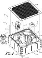
Figure 4 is an exploded view of the module illustrated inFigure 3 ; -
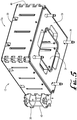
Figure 5 is a perspective view showing the underside of the module illustrated inFigure 3 ; -
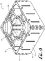
Figure 6 is a perspective view of the hull of the module illustrated inFigure 3 ; -
Figure 7 is a perspective view illustrating an edge module used in the lifting floor illustrated inFigure 1 ; -
Figure 8 is a perspective view of a portion of the lifting floor illustrated inFigure 1 , showing a pair of pool edge access doors; -
Figure 9 is a perspective view of a buoyancy assembly used within the module illustrated inFigure 3 ; -
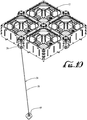
Figure 10 is a perspective view illustrating a module such as illustrated inFigure 5 having a tether attached thereto; -
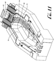
Figure 11 is a perspective view of an enclosed pool having portions of a stabilizer apparatus disposed therein; and -
Figure 12 is a perspective view of the module illustrated inFigure 3 showing additional portions of stabilizer assembly illustrated inFigure 11 attached to a module. - The following discussion describes in detail one embodiment of the invention and several variations of that embodiment. This discussion should not be construed, however, as limiting the invention to those particular embodiments. Practitioners skilled in the art will recognize numerous other embodiments as well.
- The invention is a
lifting floor 10 for use in a body of water. The body of water is typically a large confined pool, but it can also be an open body of water, such as a marina or other boat harbor. Thelifting floor 10 comprises a plurality offloat modules 12, at least onecontainer 14 disposed in each float module and adischarge apparatus 16. - The
lifting floor 10 is designed to reside on the bottom of a body of water, and, when required, usebuoyancy assemblies 32 to blow air or other low density fluid intobuoyancy compartments 28 within eachfloat module 12 -- thereby causing thelifting platform 10 to rise to at or near the surface in a very short period of time, if necessary. By "near the surface," it is meant within about 76.2 cm (30 inches) of the surface, typically within about 45.7 cm (18 inches) of the surface. - The time for the
emergency lifting floor 10 to deploy to the raised position in an emergency situation is typically 30 to 60 seconds, depending on water depth. -
Figure 1 illustrates one embodiment of thelifting floor 10 disposed on the bottom of an enclosedpool 18.Figure 2 illustrates the same embodiment raised to near its maximum height within thepool 18. - The plurality of
float modules 12 is flexibly connected to one another to yield an integral whole. All module-to-module gaps are typically about standard 15.2 cm (6") width, and are preferably filled by grating. - The plurality of
float modules 12 typically comprisesstandard modules 12a andedge modules 12b.Standard float modules 12a are used to cover as much of pool area as possible.Figure 3-6 illustrate a typicalstandard float module 12a. - Each
float module 12 comprises ahull 20 with downwardly extendingside walls 22, atop wall 24, abottom 26 and abuoyancy compartment 28. In a typical embodiment, anouter wall 22a and aninner wall 22b of thehull side walls 22 together define thebuoyancy compartment 28 therebetween. - The
bottom 26 of eachfloat module 12 is typically at least partially open and can be made of a concrete to provide proper ballast. - The
hull 20 of each standard float module can be a hollow polyethylene rotomolded part. The skin thickness can be about 0.64 cm (0.25 inches). Theside walls 22 can have a hollow double wall construction, comprising a total thickness 0.953 cm (0.375 inches) - 1.27 cm (0.5 inches), and comprising concrete and/or foam fill. Concrete fill allows the final weight to be adjusted for the desired buoyancy. Foam fill assures that themodules 12 will not fill with water and provides additional stiffening. The foam is preferably hydrophobic. - The
hull 20 of eachmodule 12 defines a largecentral opening 29 covered by agrate 30. Thegrate 30 is typically made of deck grating of an open style fiberglass that allows water to flow through themodule 12 during ascent and descent. Access hatches are provided in selectedmodules 12 to allow diver access to the area below the liftingfloor 10 when the liftingfloor 10 is raised. Thegrate 30 is removable for access tobuoyancy assemblies 32 disposed within eachmodule 12. - Disposed within each
module 12 is abuoyancy assembly 32 comprising acontainer 14, associated valves and connecting tubing. - Each
float module 12 further comprises at least oneflood valve 34 to allow water to refill thebuoyancy compartment 28. Theflood valve 34 can be an air actuated flap mechanism mounted near the top of thebuoyancy compartment 28. Theflood valve 34 is normally held closed by springs. When actuated, a pneumatic air bag style actuator forces the flaps to an open position allowing the air to be vented from thebuoyancy compartment 28, thereby flooding thebuoyancy compartment 28 and making themodule 12 negatively buoyant for descent. To minimize trapped air when the liftingfloor 10 is not level, twoflood valves 34 are preferably mounted on opposite ends ofstandard float module 12. - The underside of each
standard float module 12a comprises a plurality ofsupport feet 36 which can be made from either a plastic or a metal material. Thesupport feet 36 are dimensioned for leveling themodule 12a and allowing it to stand evenly a few inches above the floor of thepool 18. - The
standard modules 12a typically have a square top side area of between about 0.279 m2 (3 square feet) and about 0.929 m2 (10 square feet). In a typical embodiment, thestandard float modules 12a are 60.1 - 91.4 cm (24 - 36 inches) all. In one example, thestandard float modules 12a have approximately 0.65 m2 (7 square feet) of top side area and are 82.6 cm (32.5 inches) tall. - The lifting
floor 10 of the invention can be adapted for use inpools 18 of different depths. In a typical application, the pool depth is between about 4.57 m (15 feet and about 10.67 m (35 feet). Deeper pool applications can utilize a 91.4 cm (36-inch) tall float, while shallow pool applications can utilize a 60.1 cm (24-inch)tall float module 12. 91.4 cm (36-inch)float modules 12 have a largecentral opening 29 for increased flow and faster rise speeds to account for the longer travel distance in a deep pool. 60.1 cm (24-inch)float modules 12 have a smallercentral opening 29, since a slower flow rate and rise speed are required at shallower depths. - Each
float module 12 is attached toadjacent float modules 12 by means offlexible joints 38. Typically, theflexible joints 38 are disposed at the corners of eachmodule 12 and are each attached to alink retainer 40 formed into the corners of eachmodule 12. Eachlink retainer 40 is typically made from a polyurethane or other plastic and can be held in place withmetal rods 42. - Preferably, the lifting
floor 10 is disposed sufficiently proximate to the walls of thepool 18 so as to prevent a human being from falling from the liftingfloor 10 between the liftingfloor 10 and the walls of thepool 18. It is also important in the invention that the liftingfloor 10 be sufficiently close to the pool walls to prevent aquatic mammals from gaining access below the liftingfloor 10. Accordingly, the liftingfloor 10 is preferably adapted to the shape of thepool 18 where it is employed. In order to accommodate each pool shape, the periphery is fitted withedge float modules 12b that are custom shaped to closely fit the plan view of thepool 18. - The
edge float modules 12b are typically made of metal, but are otherwise comprised of the components of thestandard float modules 12a. Theedge float modules 12b have corners which are individually shaped along one or two side edges to allow each of theedge float modules 12b to closely match the surface dimensions of thepool 18. - The
edge float modules 12b preferably comprise bearing surfaces or bumpers capable of contacting theside walls 22 of thepools 18. Alternatively, theedge float modules 12b can comprise rollers capable of contacting the walls of thepool 18. - In pools 18 having a bottom with a slanted perimeter, the
edge modules 12b preferably comprise a sloped bottom 26 capable of contacting the slanted perimeter of the pool bottom when the liftingfloor 10 is disposed proximate to the pool bottom. Pads are preferably provided at the bottom of eachmodule 12 whenever themodule 12 rests against the pool bottom. - As illustrated in
Figure 7 , inpools 18 having a bottom 26 with a slanted perimeter of exceptional width, theedge modules 12b preferably comprise anedge wall 44 cantilevered off of theedge module 12b at an angle matching the slope of the slanted perimeter. Theedge walls 44 are preferably of sufficient length to reach within about 4 inches of the pool walls.Plastic rollers 46 on stainless tube shafts can be affixed to the ends of theedge walls 44 to prevent undue friction between theedge walls 44 and the pool walls. - As illustrated in
Figure 8 ,access gates 48 can be provided in one or more of theedge walls 44 to allow access between the liftingplatform 10 and the area surrounding thepool 18. - In pools 18 having corners, the
edge modules 12b typically comprise one ormore corner modules 12c, custom shaped to match the shape of the pool corners. - As noted above, each
container 14 is a component of abuoyancy assembly 32 disposed within eachfloat module 12.Figure 9 illustrates atypical buoyancy assembly 32. - Also as noted above, each
container 14 is capable of retaining an operable supply of low density fluid. In the embodiment illustrated in the drawings, thecontainer 14 is a compressed air tank, capable of retaining an operable supply of compressed air. Eachcontainer 14 has a discharge port adapted to discharge buoyancy fluid into thebuoyancy compartment 28. - The
buoyancy assembly 32 typically further comprises (i) a check valve for allowing the air tank to be pressurized and for preventing air from escaping from thecontainer 14 and (ii) ablow valve 52 attached at each discharge port which is remotely operated to allow air from thecontainer 14 to escape into thebuoyancy compartment 28. - Each
blow valve 52 is either pneumatically or electrically operated. Thus, theblow valves 52 can be solenoid valves or air actuated poppet valves. A shore based electrical signal can active each solenoid valve. A shore based air discharge activation signal can actuate each poppet valve. The solenoid valve or poppet valve typically comprises the pressure in air tanks at 2500-4000 psi (17237-27579 kPa) charge level. When actuated, eachblow valve 52 opens to fill thebuoyancy compartment 28 with air, thereby causing themodule 12 to be positively buoyant for ascent. - A
discharge apparatus 16 is provided within eachbuoyancy assembly 32 to open some or all of theblow valves 52, so as to fill eachbuoyancy compartment 28 with buoyancy fluid, thereby causing the plurality ofmodules 12 to float to a position at or near the surface of the body of water. - Preferably, the
discharge apparatus 16 is capable of opening all of theblow valves 52 simultaneously or within a few seconds of one another, such as within 3 - 10 seconds of one another. As noted above, it is preferable that the opening of a majority of theblow valves 52 can be actuated from a location disposed distant from the liftingfloor 10. - In the embodiment illustrated in the drawings, associated on board electrical and electronic control components are housed in an
electrical component pod 53 disposed in eachmodule 12. - Preferably, the
discharge apparatus 16 comprises a programmable logic controller continued capable of being programmed to open theblow valves 52 inindividual modules 12 at predetermined time intervals to maintain trim stability of thelifting platform 10 during ascent. - In pneumatic systems, the
blow valves 52 are preferably actuated by two actuator valves. The two actuator valves are interconnected to provide redundancy. The redundancy gives thedischarge opening apparatus 16 the ability to raise the liftingfloor 10 in the event of a failure of a single actuator valve. - A high pressure charge air line is typically connected to the manifold to allow the air tanks to be monitored and charged from a shore based air compressor and monitoring system. In this regard, a high pressure recharge air compressor and dryer system can be provided. A high pressure recharge system is also provided, including plumbing or piping as required to transmit high pressure air to the control valve location(s). Pneumatic piping is typically used between the local pool control valve locations. Piping is provided from the control valve locations to the lifting
floor 10. Piping is also provided to the control valve locations from a source of air compression, such as an air compressor and high pressure air supply system. The charge air line may or may not be permanently attached. The charge air line also allows make-up air to be pumped into the liftingfloor 10 when the liftingfloor 10 is raised to overcome any incidental leakage in thefloat modules 12 and maintain the liftingfloor 10 in the raised position indefinitely. - In each
module 12, the net lifting force with a fully blownbuoyancy compartment 28 is typically 1,134-1,361 kg (2,500-3,000 lbs). - Local operational control stations are provided to initiate emergency raise, routine raise and routine lower motions. Typically, one to three guarded pushbutton panels per
pool 18 are used to initiate the emergency raise motions. The routine raise and lower positions are typically initiated via a separate dedicated push-button panel. - Typically, on shore control valves are located in enclosures. Each enclosure is preferably located as close as possible to the edge of the
pool 18. - As noted above, a central programmable logic controller is used to monitor and control the lifting
floor 10 throughout the facility. The controller; - Interfaces with the operator and monitoring stations
- Provides the valve control sequencing for different operating modes
- Provides system status monitoring and error annunciation
- Provides manual control functions for system maintenance and debugging
- Controls and confirms the closing of any gates used to allow access from the
pool 18 to an adjoining pool. - The controller can be located in an electrical enclosure along with appropriate power supplies, control relays and distribution equipment.
- As noted above, during raising operations, the
lifting platform 10 can be controlled by opening theblow valves 52 in a programmed sequence. The innermodule blow valves 52 are typically activated first, followed by perimetermodule blow valves 52. - To initiate lowering operations, the
flood valves 34 are automatically cycled to bring the liftingfloor 10 to the bottom of thepool 18. During lowering operations, the liftingfloor 10 can be controlled by reacting to lifting floor depth. A command to lower the liftingfloor 10 causes theflood valves 34 to activate and theblow valves 52 to pulse to maintain attitude/levelness/trim stability. A control system algorithm used in lower operations is based on a virtual axis. The virtual axis is the target depth versus time. Each control zone is plotted and compared to virtual axis. At specified increments, the control system calculates the difference between actual depth and virtual depth. Theblow valve 52 activation time is calculated using the depth difference and a predetermined gain. The gain is a predetermined program variable. - Typically, an audible alarm is adapted to sound whenever the lifting
floor 10 is activated. The alarm type and duration can vary depending on if the liftingfloor 10 is activated in emergency or routine maintenance mode. - The controller is typically disposed in a monitoring station located in a central, control booth. Remote operator stations can be also be provided for routine operation of an
individual lifting floor 10 assembly. Remote operator stations are preferably located within direct line of sight of thepool 18. The remote operator stations are used for routine operation of the liftingfloor 10. Additional control stations can be located around thepool 18 to trigger emergency lifting floor deployment. - The lifting
floor 10 can further comprise astabilizer apparatus 54 for stabilizing the plurality ofmodules 12 during the ascent through the body of water and/or during the time that they are at a position near the surface of the body of water. - In open water applications, the
stabilizer apparatus 54 can be employed to prevent the liftingfloor 10 from fully rising to the surface. Often, restricting the rise of the liftingfloor 10 to within about 15.2 cm (6 inches) and 45.7 cm (18 inches) (for example, approximately 30.5 cm (12 inches) of the surface is preferred to minimize the effect of wind and waves on the lifting platform. In one embodiment, tethers 56 and anchor assemblies are used to limit the upward travel of the liftingfloor 10. Atypical tether 56 and anchor assembly is illustrated inFigure 9 . - The upper end of each
tether 56 is attached at its upper end to thefloat modules 12. The lower end of eachtether 56 is attached to ananchor 57 at the bottom of the body of water. - As illustrated in
Figures 11 and12 , in enclosed pool applications, thestabilizer apparatus 54 can comprisecords 58 slidably attached to the bottom of thepool 18 and fixed to one of themodules 12. Eachcord 58 is capable of being unwound under tension from the drum of awinch 60 so as to retard portions of thelifting platform 10 during the raising of thelifting platform 10. In such astabilizer apparatus 54, an external trim control system is used to monitor and control vertical stability of theoverall lifting floor 10 during ascent. The purpose of thisstabilizer apparatus 54 is to restrain a "runaway"module 12 from rising too quickly, to maintain lateral stability of theentire lifting floor 10 when it is at or near the surface and to maintain lateral position of the liftingfloor 10 when it is being lowered to the pool bottom. - In this stabilizer apparatus embodiment, the
cords 58 are typically strung within turning sheaves attached to the pool bottom. The sheaves preferably have "keepers" to maintaincords 58 in their grooves if they become slack.Cords 58 feed along the pool bottom and up the side of the pool wall to awinch 60 located pool-side. Thecords 58 reel-in and pay-out in unison using a position control system. A host processor checks to see that all themodules 12 are within an allowable elevation window of each other. A typical winch motor is a 20 hp (14.9 kW) electric VFD gear motor. - The
winches 60 are located at awinch location 62 disposed beyond one end of the pool. Edge sheaves are typically used to route thecords 58 from thewinch 60 location down the pool wall. Corner sheaves are used to route thecords 58 along chamfers to the bottom of thepool 18. Floor sheaves route thecords 58 along the bottom of the pool to flagging sheaves. Flagging sheaves route eachcord 58 to one or more connection points on selectedmodules 12. Typically, one pair ofinter-module connectors 64 located at a module corner is used to anchor each cord connection. The vertical rise of eachcord 58 to the pair ofinter-module connectors 64 can be shrouded in aconnector tube 66, typically a stainless steel tube. A second pair ofinter-module connectors 64 can be used to help react bending (for tension at the pool bottom). - The
winches 60 are typically enclosed in a housing for visual shielding and for protection of thewinches 60 and associated equipment from the elements. The wall of thepool 18 can be shielded from thecords 58 by ashroud 68 disposed along the vertical rise of the pool wall. - In a large
enclosed pool 18, wherein the liftingfloor 10 has an ascent rate of about 2.74 m (9 feet) per second, a typical gross restraint level of thestabilizer apparatus 54 is of the order of 45,360 kg (100,000 pounds). For such a restraint level, 8 to 10cords 58 can be used. Each of thecords 58 can be made of high modulus polyethylene (HMPE). Plasma 12-strand cord having a diameter of one inch can be employed. Such plasma 12-strand cord can be obtained from the Cortland Company of Cortland, New York. - An
alternative stabilizer apparatus 54 forclosed pools 18 can comprise actuators attached to the bottom of the liftingfloor 10, the actuators being fluidically energized so as to controllably assist or retard the liftingfloor 10 during the raising and lowering of the liftingfloor 10. - Another alternative stabilizer for an
enclosed pool 18 can comprise an ascent retarding device mounted within at least onefloat module 12. The retarding device is a tuneable flow-limiting orifice or awinch 60 having acord 58 with a retractable end attached to the floor of thepool 18. - Preferably, the lifting
floor 10 is capable of raising a load of 453.6 kg (1000 pounds) from a position proximate to the bottom of a body of water having a depth of 7.6 m (25 feet) to a position close to the surface of the body of water in less than about 60 seconds. - A typical embodiment directed to the raising of multiple aquatic mammals, such as killer whales, is designed for a total asset weight of 18,144 kg (40,000 lbs). 18,144 kg (40,000 lbs) is the approximate weight of four large aquatic mammals weighing 3,175 kg (7,000 lbs). and four large aquatic mammals weighing 1,361 kg (3,000 lbs). Typically, the maximum individual asset weight is 5,443 kg (12,000 lbs).
- Once in the raised position, the lifting
floor 10 is stable and allows for the movement of personnel across any area of the liftingfloor 10 to deal with any emergency. - After deployment of the raised position, the lifting
floor 10 can be lowered to the pool bottom by controlled flooding of the buoyancy compartments 28. Humans and/or aquatic mammals may be present when the liftingfloor 10 is lowered. The liftingfloor 10 is preferably equipped with lock-out/tag-out capability to allow for safe service, maintenance and cleaning of the liftingfloor 10 and all areas under the liftingfloor 10. - Also, all components which may come in contact with aquatic mammals or personnel are preferably free of sharp edges or loose parts.
- Preferably, the lifting
floor 10 is designed for a long life, such as a 20-year life. Typically, it is designed for one cycle every week, which is the equivalent of 1040 total cycles over a 20-year period. Materials used in the construction of the invention should be suitable for extended service life in the aqueous atmosphere present in the pool - such as in a chlorinated and ozonated artificial saltwater or natural seawater operating environment. Materials are selected to minimize the occurrence of discoloration, oxidation, or corrosion of each component. The liftingfloor 10 can be implemented in a variety ofpools 18 at a single location. The liftingfloors 10 for all of thepools 18 at a single location can be supported by a centralized system to provide controls for raising and lowering the individualpool lifting floors 10 and a high pressure compressor system to recharge the air tanks mounted in thefloat modules 12. - Having thus described the invention, it should be apparent that numerous structural modifications and adaptations may be resorted to without departing from the scope of the invention as described herein below by the claims.
Claims (14)
- A lifting floor (10) for use in a body of water (18), the lifting floor comprising:(a) a plurality of adjacent float modules (12), each float module comprising a plurality of flexible joints (38) disposed on respective corners of the float module, each flexible joint (38) attached to a link retainer (40) formed into the corner of each module (12) and held in place with metal rods (42), each float module flexibly attached to an adjacent float module by means of the flexible joints, each float module comprising a hull (20) comprising a plurality of downwardly extending side walls (22), a top wall (24) connected to the plurality of downwardly extending side walls, a bottom (26) connected to the plurality of downwardly extending side walls and a buoyancy compartment (28) disposed within the hull;(b) each float module (12) further comprising at least one container (14) disposed within the float module (12), the container (14) configured to retain a buoyancy fluid having a density less than that of water; and(c) a discharger apparatus (16) comprising a controller capable of being programmed to discharge buoyancy fluid to the buoyancy compartments in different modules at different time intervals so as to fill the buoyancy compartments of some or all of the float modules with buoyancy fluid, thereby causing the plurality of float modules to float to a position at or near the surface of the body of water.
- The lifting floor of claim 1 wherein the discharger apparatus is configured to be capable of discharging buoyancy fluid to the buoyancy compartments (28) of all float modules within zero (0) to ten (10) seconds of one another.
- The lifting floor of claim 1 wherein the bottom (26) of each float module (12) is at least partially open.
- The lifting floor of claim 1 further comprising a stabilizer (54) configured to stabilize the plurality of float modules (12) during their ascent through the body of water and during the time that they are at a position near the surface of the body of water.
- The lifting floor of claim 1 wherein the lifting floor is configured to be capable of raising a load disposed upon the lifting floor weighing greater than about 453.6kg (1000 pounds)
- The lifting floor of claim 1 wherein the lifting floor is configured to be capable of raising a load of 453.6kg (1000 pounds) from a position proximate to the bottom of a body of water having a depth of 7.62m (25 feet) to a position close to the surface of the body of water in less than about 60 seconds.
- The lifting floor of claim 1 wherein the discharger (16) is configured to be actuated from a location disposed distant from the lifting floor.
- The lifting floor of claim 4 wherein the lifting floor (10) comprises a top side and a bottom side, and wherein the stabilizer (54) comprises cords (58) slidably attached to the bottom of the pool and fixed to one of the modules (12), the cords being capable of being unwound under tension from winch drums (60) so as to retard portions of the lifting platform during the raising of the lifting platform.
- The lifting floor of claim 1 wherein the discharger apparatus (16) is capable of being programmed to discharge buoyancy fluid to the buoyancy compartments (28) in different modules at predetermined time intervals.
- The lifting floor of claim 1 wherein the modules (12) comprise
standard modules (12a) having a predetermined set of physical dimensions defining a top view area of between about 0.279m2 (3 square feet) and about 0.929m2 (10 square feet) and edge modules (12b). - The lifting floor of claim 1 wherein the lifting floor is disposed sufficiently proximate to the walls of the pool so as to prevent a human being from falling from the lifting floor between the lifting floor and the walls (22) of the pool (18).
- The lifting floor of claim 11 wherein the edge modules (12b) comprise rollers (46) capable of contacting the walls (22) of the pool (18) during the raising and lowering of the lifting floor.
- The lifting floor of claim 11 wherein the edge modules (12b) comprise bearing surfaces or bumpers capable of contacting the side walls (22) of the pool (18).
- The lifting floor of claim 11 wherein the pool (18) comprises a bottom having a slanted perimeter and wherein the edge modules (12b) comprise a sloped edge wall (44) capable of contacting the slanted perimeter of the pool bottom when the lifting floor is disposed proximate to the pool bottom.
Applications Claiming Priority (3)
| Application Number | Priority Date | Filing Date | Title |
|---|---|---|---|
| US201261583453P | 2012-01-05 | 2012-01-05 | |
| US13/733,429 US8978570B2 (en) | 2012-01-05 | 2013-01-03 | Lifting floor for bodies of water |
| PCT/US2013/020333 WO2013103856A1 (en) | 2012-01-05 | 2013-01-04 | Lifting floor for bodies of water |
Publications (3)
| Publication Number | Publication Date |
|---|---|
| EP2839097A1 EP2839097A1 (en) | 2015-02-25 |
| EP2839097A4 EP2839097A4 (en) | 2016-04-06 |
| EP2839097B1 true EP2839097B1 (en) | 2020-04-08 |
Family
ID=48743008
Family Applications (1)
| Application Number | Title | Priority Date | Filing Date |
|---|---|---|---|
| EP13733936.2A Active EP2839097B1 (en) | 2012-01-05 | 2013-01-04 | Lifting floor for bodies of water |
Country Status (7)
| Country | Link |
|---|---|
| US (1) | US8978570B2 (en) |
| EP (1) | EP2839097B1 (en) |
| JP (1) | JP6449652B2 (en) |
| CA (1) | CA2860695C (en) |
| DK (1) | DK2839097T3 (en) |
| ES (1) | ES2801050T3 (en) |
| WO (1) | WO2013103856A1 (en) |
Families Citing this family (10)
| Publication number | Priority date | Publication date | Assignee | Title |
|---|---|---|---|---|
| EP2356299B1 (en) * | 2008-11-17 | 2020-09-30 | Dovi Brock | A method and a system for rapidly and controlled elevation of a raisable floor for pools |
| US9878506B2 (en) | 2014-12-22 | 2018-01-30 | Massachusetts Institute Of Technology | Compliant yet tough hydrogel systems as ultrasound transmission agents |
| JP6572633B2 (en) * | 2015-06-09 | 2019-09-11 | 株式会社Ihi | Underwater drone transport device |
| US20170167151A1 (en) * | 2015-12-10 | 2017-06-15 | Elazar Segal | Lifesaving system and method for swimming pool |
| PT110367A (en) * | 2017-10-25 | 2019-04-26 | Jose Manuel Almeida Ferreira | MODULE FOR POOL DEPTH REDUCTION PLATFORM AND SYSTEM CONTAINING IT. |
| AT522263B1 (en) * | 2019-03-06 | 2021-12-15 | Georg Hof | Cover device for a liquid container |
| GB2602352A (en) * | 2020-12-24 | 2022-06-29 | Toumazis Antonios | Apparatus for use in a liquid pool |
| JP2024006350A (en) * | 2022-07-01 | 2024-01-17 | 株式会社ダイセル | rescue equipment |
| IT202200021774A1 (en) * | 2022-10-21 | 2024-04-21 | Torino Politecnico | FLOATING PLATFORM |
| LU504832B1 (en) * | 2023-07-28 | 2025-01-28 | Luxembourg Inst Science & Tech List | Device for capturing images of aquatic animals like amphibians, with ballast cavities |
Family Cites Families (53)
| Publication number | Priority date | Publication date | Assignee | Title |
|---|---|---|---|---|
| US2928103A (en) | 1957-05-21 | 1960-03-15 | Edgar P Turner | Safety type swimming pools |
| US2970320A (en) | 1959-01-12 | 1961-02-07 | Lifeguard Swim Pool Corp | Combination swimming pool cover and floor |
| DE6925223U (en) | 1969-06-25 | 1969-11-20 | Emil Gansloser | SWIMMING POOL INTERLAY |
| US3590399A (en) | 1969-10-14 | 1971-07-06 | Bernard G Madden | Attitude controlled flotation system |
| US3734113A (en) | 1969-10-14 | 1973-05-22 | B Madden | Attitude controlled valve |
| US3668711A (en) | 1971-01-21 | 1972-06-13 | Charles J Liermann | Swimming pool cover and rescue device |
| JPS5119676B2 (en) | 1971-08-17 | 1976-06-18 | ||
| US3760432A (en) | 1972-06-08 | 1973-09-25 | F Glorisi | Safety system for swimming pool |
| DE7300431U (en) * | 1973-01-08 | 1973-04-05 | Durette Kunststoff Gmbh & Co Kg | Cover for a liquid pool |
| US3955797A (en) | 1974-01-24 | 1976-05-11 | Autoquip Corporation | Swimming pool lift |
| FR2336533A1 (en) | 1975-12-22 | 1977-07-22 | Schiron Klaus | MOBILE BACKGROUND FOR SWIMMING POOLS |
| US4283801A (en) | 1977-03-08 | 1981-08-18 | Smith Francis C | Hydraulic cylinder for multilevel submersible safety deck or decks for pools |
| US4229843A (en) | 1978-07-18 | 1980-10-28 | Bombardier Limited | Pool floor |
| JPS55143345U (en) * | 1979-04-03 | 1980-10-14 | ||
| US4364131A (en) | 1979-08-17 | 1982-12-21 | Clerk Robert C | Liquid reservoir |
| US4266500A (en) * | 1979-09-24 | 1981-05-12 | Bunker Ramo Corporation | Hover control system for a submersible buoy |
| US4692906A (en) * | 1984-01-04 | 1987-09-08 | Mobil Oil Corporation | Ocean bottom seisometer |
| US4574404A (en) | 1984-02-21 | 1986-03-11 | Stark Sr Robert G | Airlift bulkhead |
| US4604962A (en) | 1985-01-28 | 1986-08-12 | Denis Guibault | Modular floating dock |
| US4937896A (en) | 1985-09-27 | 1990-07-03 | Masateru Niimura | Floor-level adjusting device for a pool |
| US4831672A (en) | 1985-09-27 | 1989-05-23 | Masateru Niimura | Floor-level adjusting device for a pool |
| CN1013391B (en) | 1986-08-26 | 1991-07-31 | 新村正照 | Bottom apparatus for swimming pool |
| JPS63162699U (en) * | 1987-04-14 | 1988-10-24 | ||
| JPH0185198U (en) * | 1987-11-28 | 1989-06-06 | ||
| JPH01273783A (en) * | 1988-04-26 | 1989-11-01 | Yamaha Motor Co Ltd | Floating element combination type water floating body |
| JPH02127373A (en) | 1988-11-07 | 1990-05-16 | Mitsubishi Electric Corp | Drive control device |
| JP2819474B2 (en) * | 1989-09-20 | 1998-10-30 | 株式会社石井鐵工所 | Float type movable pool floor and its installation method |
| FR2685727A1 (en) | 1991-12-27 | 1993-07-02 | Thil Albert | COVERING DEVICE FOR SWIMMING POOL OR RIGID BASIN. |
| JPH06144364A (en) * | 1992-11-10 | 1994-05-24 | Nippon Steel Corp | Large floating structure |
| US5271483A (en) | 1992-12-02 | 1993-12-21 | Hong Young K | Apparatus for lifting false floor in swimming pool |
| NL9401914A (en) | 1994-11-16 | 1996-07-01 | Polymarin Bv | Swimming pool basin with adjustable partition. |
| US5522671A (en) | 1995-04-17 | 1996-06-04 | Keesling; Klinton H. | Hydraulic boat lift |
| US5692857A (en) | 1995-09-21 | 1997-12-02 | Ness; Stewart D. | Lifting floors |
| US5678253A (en) | 1996-06-28 | 1997-10-21 | Baker; William H. | Adjustable pool flooring structure |
| US5832547A (en) | 1996-11-12 | 1998-11-10 | Burroughs; Vance | Swimming pool automatic rescue device |
| US5931113A (en) | 1997-09-12 | 1999-08-03 | Ocean Innovations, Inc. | Floating drive on dry dock assembly having a supporting beam |
| DE19745746C2 (en) | 1997-10-16 | 2000-09-07 | Kbe Bauelemente Gmbh & Co Kg | Height-adjustable shelf for multi-purpose pools |
| JP4085464B2 (en) | 1998-04-20 | 2008-05-14 | ソニー株式会社 | Video camera |
| IL147443A0 (en) | 1999-07-16 | 2002-08-14 | Boujon Claire Lise | Safety and life-saving device for aquatic environment |
| US6253390B1 (en) | 2000-04-11 | 2001-07-03 | Precision Fibre Structures Inc. | Aquatic raisable floor apparatus |
| US6640504B2 (en) | 2000-09-11 | 2003-11-04 | Flg Industries, Inc. | Moveable swimming pool floor |
| DE10118208C1 (en) * | 2001-04-17 | 2002-04-04 | Rainer Dumont | Swimming pool cover is formed from individual elements each provided with hollow chamber of variable volume used for lowering and raising cover |
| US7249386B2 (en) | 2003-10-24 | 2007-07-31 | Terzo Michael B | Portable pool lift for disabled persons |
| US7213531B2 (en) * | 2004-02-12 | 2007-05-08 | Roy Ahern | Multidirectional floating dock element |
| US7426898B1 (en) * | 2004-02-12 | 2008-09-23 | Roy Ahern | Floating berth modular dock system assembly |
| FR2866381B1 (en) | 2004-02-18 | 2006-05-19 | Raymond Nexon | PROFILE FOR THE CONSTRUCTION OF FLOOR FLOORS AND LIKELY TO FLOAT OR IMMERSE |
| JP2006160025A (en) * | 2004-12-06 | 2006-06-22 | Rikogaku Shinkokai | Underwater moving body and aerial moving body |
| JP4745116B2 (en) | 2005-06-10 | 2011-08-10 | 延幸 高橋 | Water tank lifting floor, unit for assembling the water tank lifting floor, and method for assembling the water tank lifting floor |
| US20090126096A1 (en) | 2007-11-15 | 2009-05-21 | Juan Carlos Bocos | Elevator assembly for swimming pool |
| FR2928951B1 (en) | 2008-03-19 | 2016-07-01 | Frederic Juracek | MOBILE BACKGROUND DEVICE FOR SWIMMING POOL |
| EP2356299B1 (en) * | 2008-11-17 | 2020-09-30 | Dovi Brock | A method and a system for rapidly and controlled elevation of a raisable floor for pools |
| US20100122406A1 (en) | 2008-11-19 | 2010-05-20 | Gschwind Carlos Alberto | Pneumatic powered lift for swimming pools |
| US8001626B2 (en) | 2009-01-27 | 2011-08-23 | Walter Dalickas | Swimming pool safety net system |
-
2013
- 2013-01-03 US US13/733,429 patent/US8978570B2/en active Active
- 2013-01-04 DK DK13733936.2T patent/DK2839097T3/en active
- 2013-01-04 CA CA2860695A patent/CA2860695C/en active Active
- 2013-01-04 WO PCT/US2013/020333 patent/WO2013103856A1/en not_active Ceased
- 2013-01-04 EP EP13733936.2A patent/EP2839097B1/en active Active
- 2013-01-04 JP JP2014551346A patent/JP6449652B2/en active Active
- 2013-01-04 ES ES13733936T patent/ES2801050T3/en active Active
Non-Patent Citations (1)
| Title |
|---|
| None * |
Also Published As
| Publication number | Publication date |
|---|---|
| CA2860695C (en) | 2019-08-20 |
| WO2013103856A1 (en) | 2013-07-11 |
| EP2839097A4 (en) | 2016-04-06 |
| EP2839097A1 (en) | 2015-02-25 |
| CA2860695A1 (en) | 2013-07-11 |
| ES2801050T3 (en) | 2021-01-08 |
| US20130174770A1 (en) | 2013-07-11 |
| DK2839097T3 (en) | 2020-07-13 |
| JP6449652B2 (en) | 2019-01-09 |
| JP2015513493A (en) | 2015-05-14 |
| US8978570B2 (en) | 2015-03-17 |
Similar Documents
| Publication | Publication Date | Title |
|---|---|---|
| US8978570B2 (en) | Lifting floor for bodies of water | |
| EP3387631B1 (en) | Lifesaving system and method for swimming pool | |
| US10086919B2 (en) | Boat lift | |
| CA2741350C (en) | Device for extinguishing fires | |
| KR20140029880A (en) | Airbag pontoon | |
| KR20080102398A (en) | Deep sea | |
| US4087980A (en) | Safety submarine spherical air chamber | |
| CN103687786B (en) | Inflated type floatable device | |
| US6389615B2 (en) | Fail-safe safety swimming pool net | |
| KR101685597B1 (en) | Ship Search and Rescue simulator system for training | |
| EP2920052A1 (en) | Arrangement and method for underwater activities | |
| EP2356299B1 (en) | A method and a system for rapidly and controlled elevation of a raisable floor for pools | |
| KR101058393B1 (en) | Dock working ship | |
| JP6552124B2 (en) | Submersible shelter | |
| KR20180052210A (en) | Ship for rescue | |
| KR102150664B1 (en) | Seawater swimming pool floated on the sea | |
| US3500785A (en) | System for salvaging submerged objects | |
| RU2054250C1 (en) | Apparatus for keeping hydrobionts | |
| WO2018175934A1 (en) | Boat lift | |
| RU2479460C1 (en) | Method of sunk ship surfacing and complex for surfacing and floating sunk submarines and other vessels | |
| KR101050902B1 (en) | Day and night wildfire extinguishing device using helicopter and wildfire extinguishing method using same | |
| RU2564271C1 (en) | Method of sunken ship surfacing and complex for surfacing and floating sunken submarines and other vessels | |
| ES2631010T3 (en) | Vessel with vertical draft system | |
| KR102065553B1 (en) | Life-saving Tube Device and Control Method thereof | |
| KR20110029318A (en) | Flotation |
Legal Events
| Date | Code | Title | Description |
|---|---|---|---|
| PUAI | Public reference made under article 153(3) epc to a published international application that has entered the european phase |
Free format text: ORIGINAL CODE: 0009012 |
|
| 17P | Request for examination filed |
Effective date: 20140715 |
|
| AK | Designated contracting states |
Kind code of ref document: A1 Designated state(s): AL AT BE BG CH CY CZ DE DK EE ES FI FR GB GR HR HU IE IS IT LI LT LU LV MC MK MT NL NO PL PT RO RS SE SI SK SM TR |
|
| AX | Request for extension of the european patent |
Extension state: BA ME |
|
| DAX | Request for extension of the european patent (deleted) | ||
| RA4 | Supplementary search report drawn up and despatched (corrected) |
Effective date: 20160307 |
|
| RIC1 | Information provided on ipc code assigned before grant |
Ipc: E04H 4/06 20060101ALI20160301BHEP Ipc: E04H 4/14 20060101AFI20160301BHEP |
|
| STAA | Information on the status of an ep patent application or granted ep patent |
Free format text: STATUS: EXAMINATION IS IN PROGRESS |
|
| 17Q | First examination report despatched |
Effective date: 20171207 |
|
| GRAP | Despatch of communication of intention to grant a patent |
Free format text: ORIGINAL CODE: EPIDOSNIGR1 |
|
| STAA | Information on the status of an ep patent application or granted ep patent |
Free format text: STATUS: GRANT OF PATENT IS INTENDED |
|
| INTG | Intention to grant announced |
Effective date: 20191016 |
|
| GRAS | Grant fee paid |
Free format text: ORIGINAL CODE: EPIDOSNIGR3 |
|
| GRAA | (expected) grant |
Free format text: ORIGINAL CODE: 0009210 |
|
| STAA | Information on the status of an ep patent application or granted ep patent |
Free format text: STATUS: THE PATENT HAS BEEN GRANTED |
|
| AK | Designated contracting states |
Kind code of ref document: B1 Designated state(s): AL AT BE BG CH CY CZ DE DK EE ES FI FR GB GR HR HU IE IS IT LI LT LU LV MC MK MT NL NO PL PT RO RS SE SI SK SM TR |
|
| REG | Reference to a national code |
Ref country code: AT Ref legal event code: REF Ref document number: 1254580 Country of ref document: AT Kind code of ref document: T Effective date: 20200415 Ref country code: CH Ref legal event code: EP |
|
| REG | Reference to a national code |
Ref country code: DE Ref legal event code: R096 Ref document number: 602013067672 Country of ref document: DE |
|
| RAP2 | Party data changed (patent owner data changed or rights of a patent transferred) |
Owner name: OCEANEERING INTERNATIONAL, INC. |
|
| REG | Reference to a national code |
Ref country code: IE Ref legal event code: FG4D |
|
| REG | Reference to a national code |
Ref country code: DK Ref legal event code: T3 Effective date: 20200709 |
|
| REG | Reference to a national code |
Ref country code: NL Ref legal event code: FP |
|
| REG | Reference to a national code |
Ref country code: NO Ref legal event code: T2 Effective date: 20200408 |
|
| REG | Reference to a national code |
Ref country code: LT Ref legal event code: MG4D |
|
| PG25 | Lapsed in a contracting state [announced via postgrant information from national office to epo] |
Ref country code: PT Free format text: LAPSE BECAUSE OF FAILURE TO SUBMIT A TRANSLATION OF THE DESCRIPTION OR TO PAY THE FEE WITHIN THE PRESCRIBED TIME-LIMIT Effective date: 20200817 Ref country code: LT Free format text: LAPSE BECAUSE OF FAILURE TO SUBMIT A TRANSLATION OF THE DESCRIPTION OR TO PAY THE FEE WITHIN THE PRESCRIBED TIME-LIMIT Effective date: 20200408 Ref country code: SE Free format text: LAPSE BECAUSE OF FAILURE TO SUBMIT A TRANSLATION OF THE DESCRIPTION OR TO PAY THE FEE WITHIN THE PRESCRIBED TIME-LIMIT Effective date: 20200408 Ref country code: IS Free format text: LAPSE BECAUSE OF FAILURE TO SUBMIT A TRANSLATION OF THE DESCRIPTION OR TO PAY THE FEE WITHIN THE PRESCRIBED TIME-LIMIT Effective date: 20200808 Ref country code: FI Free format text: LAPSE BECAUSE OF FAILURE TO SUBMIT A TRANSLATION OF THE DESCRIPTION OR TO PAY THE FEE WITHIN THE PRESCRIBED TIME-LIMIT Effective date: 20200408 Ref country code: GR Free format text: LAPSE BECAUSE OF FAILURE TO SUBMIT A TRANSLATION OF THE DESCRIPTION OR TO PAY THE FEE WITHIN THE PRESCRIBED TIME-LIMIT Effective date: 20200709 |
|
| REG | Reference to a national code |
Ref country code: AT Ref legal event code: MK05 Ref document number: 1254580 Country of ref document: AT Kind code of ref document: T Effective date: 20200408 |
|
| PG25 | Lapsed in a contracting state [announced via postgrant information from national office to epo] |
Ref country code: HR Free format text: LAPSE BECAUSE OF FAILURE TO SUBMIT A TRANSLATION OF THE DESCRIPTION OR TO PAY THE FEE WITHIN THE PRESCRIBED TIME-LIMIT Effective date: 20200408 Ref country code: LV Free format text: LAPSE BECAUSE OF FAILURE TO SUBMIT A TRANSLATION OF THE DESCRIPTION OR TO PAY THE FEE WITHIN THE PRESCRIBED TIME-LIMIT Effective date: 20200408 Ref country code: BG Free format text: LAPSE BECAUSE OF FAILURE TO SUBMIT A TRANSLATION OF THE DESCRIPTION OR TO PAY THE FEE WITHIN THE PRESCRIBED TIME-LIMIT Effective date: 20200708 Ref country code: RS Free format text: LAPSE BECAUSE OF FAILURE TO SUBMIT A TRANSLATION OF THE DESCRIPTION OR TO PAY THE FEE WITHIN THE PRESCRIBED TIME-LIMIT Effective date: 20200408 |
|
| PG25 | Lapsed in a contracting state [announced via postgrant information from national office to epo] |
Ref country code: AL Free format text: LAPSE BECAUSE OF FAILURE TO SUBMIT A TRANSLATION OF THE DESCRIPTION OR TO PAY THE FEE WITHIN THE PRESCRIBED TIME-LIMIT Effective date: 20200408 |
|
| REG | Reference to a national code |
Ref country code: ES Ref legal event code: FG2A Ref document number: 2801050 Country of ref document: ES Kind code of ref document: T3 Effective date: 20210108 |
|
| REG | Reference to a national code |
Ref country code: DE Ref legal event code: R097 Ref document number: 602013067672 Country of ref document: DE |
|
| PG25 | Lapsed in a contracting state [announced via postgrant information from national office to epo] |
Ref country code: CZ Free format text: LAPSE BECAUSE OF FAILURE TO SUBMIT A TRANSLATION OF THE DESCRIPTION OR TO PAY THE FEE WITHIN THE PRESCRIBED TIME-LIMIT Effective date: 20200408 Ref country code: RO Free format text: LAPSE BECAUSE OF FAILURE TO SUBMIT A TRANSLATION OF THE DESCRIPTION OR TO PAY THE FEE WITHIN THE PRESCRIBED TIME-LIMIT Effective date: 20200408 Ref country code: AT Free format text: LAPSE BECAUSE OF FAILURE TO SUBMIT A TRANSLATION OF THE DESCRIPTION OR TO PAY THE FEE WITHIN THE PRESCRIBED TIME-LIMIT Effective date: 20200408 Ref country code: EE Free format text: LAPSE BECAUSE OF FAILURE TO SUBMIT A TRANSLATION OF THE DESCRIPTION OR TO PAY THE FEE WITHIN THE PRESCRIBED TIME-LIMIT Effective date: 20200408 Ref country code: SM Free format text: LAPSE BECAUSE OF FAILURE TO SUBMIT A TRANSLATION OF THE DESCRIPTION OR TO PAY THE FEE WITHIN THE PRESCRIBED TIME-LIMIT Effective date: 20200408 |
|
| PLBE | No opposition filed within time limit |
Free format text: ORIGINAL CODE: 0009261 |
|
| STAA | Information on the status of an ep patent application or granted ep patent |
Free format text: STATUS: NO OPPOSITION FILED WITHIN TIME LIMIT |
|
| PG25 | Lapsed in a contracting state [announced via postgrant information from national office to epo] |
Ref country code: PL Free format text: LAPSE BECAUSE OF FAILURE TO SUBMIT A TRANSLATION OF THE DESCRIPTION OR TO PAY THE FEE WITHIN THE PRESCRIBED TIME-LIMIT Effective date: 20200408 Ref country code: SK Free format text: LAPSE BECAUSE OF FAILURE TO SUBMIT A TRANSLATION OF THE DESCRIPTION OR TO PAY THE FEE WITHIN THE PRESCRIBED TIME-LIMIT Effective date: 20200408 |
|
| 26N | No opposition filed |
Effective date: 20210112 |
|
| PG25 | Lapsed in a contracting state [announced via postgrant information from national office to epo] |
Ref country code: SI Free format text: LAPSE BECAUSE OF FAILURE TO SUBMIT A TRANSLATION OF THE DESCRIPTION OR TO PAY THE FEE WITHIN THE PRESCRIBED TIME-LIMIT Effective date: 20200408 |
|
| PG25 | Lapsed in a contracting state [announced via postgrant information from national office to epo] |
Ref country code: MC Free format text: LAPSE BECAUSE OF FAILURE TO SUBMIT A TRANSLATION OF THE DESCRIPTION OR TO PAY THE FEE WITHIN THE PRESCRIBED TIME-LIMIT Effective date: 20200408 |
|
| REG | Reference to a national code |
Ref country code: CH Ref legal event code: PL |
|
| PG25 | Lapsed in a contracting state [announced via postgrant information from national office to epo] |
Ref country code: LU Free format text: LAPSE BECAUSE OF NON-PAYMENT OF DUE FEES Effective date: 20210104 |
|
| REG | Reference to a national code |
Ref country code: BE Ref legal event code: MM Effective date: 20210131 |
|
| PG25 | Lapsed in a contracting state [announced via postgrant information from national office to epo] |
Ref country code: CH Free format text: LAPSE BECAUSE OF NON-PAYMENT OF DUE FEES Effective date: 20210131 Ref country code: LI Free format text: LAPSE BECAUSE OF NON-PAYMENT OF DUE FEES Effective date: 20210131 |
|
| PG25 | Lapsed in a contracting state [announced via postgrant information from national office to epo] |
Ref country code: IE Free format text: LAPSE BECAUSE OF NON-PAYMENT OF DUE FEES Effective date: 20210104 |
|
| PG25 | Lapsed in a contracting state [announced via postgrant information from national office to epo] |
Ref country code: BE Free format text: LAPSE BECAUSE OF NON-PAYMENT OF DUE FEES Effective date: 20210131 |
|
| PG25 | Lapsed in a contracting state [announced via postgrant information from national office to epo] |
Ref country code: HU Free format text: LAPSE BECAUSE OF FAILURE TO SUBMIT A TRANSLATION OF THE DESCRIPTION OR TO PAY THE FEE WITHIN THE PRESCRIBED TIME-LIMIT; INVALID AB INITIO Effective date: 20130104 |
|
| PG25 | Lapsed in a contracting state [announced via postgrant information from national office to epo] |
Ref country code: CY Free format text: LAPSE BECAUSE OF FAILURE TO SUBMIT A TRANSLATION OF THE DESCRIPTION OR TO PAY THE FEE WITHIN THE PRESCRIBED TIME-LIMIT Effective date: 20200408 |
|
| P01 | Opt-out of the competence of the unified patent court (upc) registered |
Effective date: 20230526 |
|
| PG25 | Lapsed in a contracting state [announced via postgrant information from national office to epo] |
Ref country code: MK Free format text: LAPSE BECAUSE OF FAILURE TO SUBMIT A TRANSLATION OF THE DESCRIPTION OR TO PAY THE FEE WITHIN THE PRESCRIBED TIME-LIMIT Effective date: 20200408 |
|
| PG25 | Lapsed in a contracting state [announced via postgrant information from national office to epo] |
Ref country code: TR Free format text: LAPSE BECAUSE OF FAILURE TO SUBMIT A TRANSLATION OF THE DESCRIPTION OR TO PAY THE FEE WITHIN THE PRESCRIBED TIME-LIMIT Effective date: 20200408 |
|
| PG25 | Lapsed in a contracting state [announced via postgrant information from national office to epo] |
Ref country code: MT Free format text: LAPSE BECAUSE OF FAILURE TO SUBMIT A TRANSLATION OF THE DESCRIPTION OR TO PAY THE FEE WITHIN THE PRESCRIBED TIME-LIMIT Effective date: 20200408 |
|
| PGFP | Annual fee paid to national office [announced via postgrant information from national office to epo] |
Ref country code: GB Payment date: 20251211 Year of fee payment: 14 |
|
| PGFP | Annual fee paid to national office [announced via postgrant information from national office to epo] |
Ref country code: NL Payment date: 20251225 Year of fee payment: 14 Ref country code: FR Payment date: 20251222 Year of fee payment: 14 |
|
| PGFP | Annual fee paid to national office [announced via postgrant information from national office to epo] |
Ref country code: ES Payment date: 20260206 Year of fee payment: 14 |
|
| PGFP | Annual fee paid to national office [announced via postgrant information from national office to epo] |
Ref country code: DE Payment date: 20251216 Year of fee payment: 14 Ref country code: NO Payment date: 20260109 Year of fee payment: 14 Ref country code: DK Payment date: 20260113 Year of fee payment: 14 |
|
| PGFP | Annual fee paid to national office [announced via postgrant information from national office to epo] |
Ref country code: IT Payment date: 20251230 Year of fee payment: 14 |