EP2835325A1 - Conveyance system - Google Patents
Conveyance system Download PDFInfo
- Publication number
- EP2835325A1 EP2835325A1 EP13772486.0A EP13772486A EP2835325A1 EP 2835325 A1 EP2835325 A1 EP 2835325A1 EP 13772486 A EP13772486 A EP 13772486A EP 2835325 A1 EP2835325 A1 EP 2835325A1
- Authority
- EP
- European Patent Office
- Prior art keywords
- stacker crane
- identification information
- conveyance
- objects
- storage rack
- Prior art date
- Legal status (The legal status is an assumption and is not a legal conclusion. Google has not performed a legal analysis and makes no representation as to the accuracy of the status listed.)
- Granted
Links
Images


Classifications
-
- B—PERFORMING OPERATIONS; TRANSPORTING
- B65—CONVEYING; PACKING; STORING; HANDLING THIN OR FILAMENTARY MATERIAL
- B65G—TRANSPORT OR STORAGE DEVICES, e.g. CONVEYORS FOR LOADING OR TIPPING, SHOP CONVEYOR SYSTEMS OR PNEUMATIC TUBE CONVEYORS
- B65G1/00—Storing articles, individually or in orderly arrangement, in warehouses or magazines
- B65G1/02—Storage devices
- B65G1/04—Storage devices mechanical
- B65G1/0407—Storage devices mechanical using stacker cranes
- B65G1/0421—Storage devices mechanical using stacker cranes with control for stacker crane operations
-
- B—PERFORMING OPERATIONS; TRANSPORTING
- B65—CONVEYING; PACKING; STORING; HANDLING THIN OR FILAMENTARY MATERIAL
- B65G—TRANSPORT OR STORAGE DEVICES, e.g. CONVEYORS FOR LOADING OR TIPPING, SHOP CONVEYOR SYSTEMS OR PNEUMATIC TUBE CONVEYORS
- B65G1/00—Storing articles, individually or in orderly arrangement, in warehouses or magazines
- B65G1/02—Storage devices
- B65G1/04—Storage devices mechanical
-
- B—PERFORMING OPERATIONS; TRANSPORTING
- B65—CONVEYING; PACKING; STORING; HANDLING THIN OR FILAMENTARY MATERIAL
- B65G—TRANSPORT OR STORAGE DEVICES, e.g. CONVEYORS FOR LOADING OR TIPPING, SHOP CONVEYOR SYSTEMS OR PNEUMATIC TUBE CONVEYORS
- B65G1/00—Storing articles, individually or in orderly arrangement, in warehouses or magazines
- B65G1/02—Storage devices
- B65G1/04—Storage devices mechanical
- B65G1/137—Storage devices mechanical with arrangements or automatic control means for selecting which articles are to be removed
-
- B—PERFORMING OPERATIONS; TRANSPORTING
- B65—CONVEYING; PACKING; STORING; HANDLING THIN OR FILAMENTARY MATERIAL
- B65G—TRANSPORT OR STORAGE DEVICES, e.g. CONVEYORS FOR LOADING OR TIPPING, SHOP CONVEYOR SYSTEMS OR PNEUMATIC TUBE CONVEYORS
- B65G49/00—Conveying systems characterised by their application for specified purposes not otherwise provided for
- B65G49/05—Conveying systems characterised by their application for specified purposes not otherwise provided for for fragile or damageable materials or articles
- B65G49/07—Conveying systems characterised by their application for specified purposes not otherwise provided for for fragile or damageable materials or articles for semiconductor wafers Not used, see H10P72/00
-
- G—PHYSICS
- G05—CONTROLLING; REGULATING
- G05B—CONTROL OR REGULATING SYSTEMS IN GENERAL; FUNCTIONAL ELEMENTS OF SUCH SYSTEMS; MONITORING OR TESTING ARRANGEMENTS FOR SUCH SYSTEMS OR ELEMENTS
- G05B19/00—Program-control systems
- G05B19/02—Program-control systems electric
- G05B19/418—Total factory control, i.e. centrally controlling a plurality of machines, e.g. direct or distributed numerical control [DNC], flexible manufacturing systems [FMS], integrated manufacturing systems [IMS] or computer integrated manufacturing [CIM]
-
- H—ELECTRICITY
- H10—SEMICONDUCTOR DEVICES; ELECTRIC SOLID-STATE DEVICES NOT OTHERWISE PROVIDED FOR
- H10P—GENERIC PROCESSES OR APPARATUS FOR THE MANUFACTURE OR TREATMENT OF DEVICES COVERED BY CLASS H10
- H10P72/00—Handling or holding of wafers, substrates or devices during manufacture or treatment thereof
- H10P72/06—Apparatus for monitoring, sorting, marking, testing or measuring
- H10P72/0618—Apparatus for monitoring, sorting, marking, testing or measuring using identification means, e.g. labels on substrates or labels on containers
-
- H—ELECTRICITY
- H10—SEMICONDUCTOR DEVICES; ELECTRIC SOLID-STATE DEVICES NOT OTHERWISE PROVIDED FOR
- H10P—GENERIC PROCESSES OR APPARATUS FOR THE MANUFACTURE OR TREATMENT OF DEVICES COVERED BY CLASS H10
- H10P72/00—Handling or holding of wafers, substrates or devices during manufacture or treatment thereof
- H10P72/30—Handling or holding of wafers, substrates or devices during manufacture or treatment thereof for conveying, e.g. between different workstations
-
- H—ELECTRICITY
- H10—SEMICONDUCTOR DEVICES; ELECTRIC SOLID-STATE DEVICES NOT OTHERWISE PROVIDED FOR
- H10P—GENERIC PROCESSES OR APPARATUS FOR THE MANUFACTURE OR TREATMENT OF DEVICES COVERED BY CLASS H10
- H10P72/00—Handling or holding of wafers, substrates or devices during manufacture or treatment thereof
- H10P72/30—Handling or holding of wafers, substrates or devices during manufacture or treatment thereof for conveying, e.g. between different workstations
- H10P72/34—Handling or holding of wafers, substrates or devices during manufacture or treatment thereof for conveying, e.g. between different workstations the wafers being stored in a carrier, involving loading and unloading
- H10P72/3404—Storage means
-
- B—PERFORMING OPERATIONS; TRANSPORTING
- B65—CONVEYING; PACKING; STORING; HANDLING THIN OR FILAMENTARY MATERIAL
- B65G—TRANSPORT OR STORAGE DEVICES, e.g. CONVEYORS FOR LOADING OR TIPPING, SHOP CONVEYOR SYSTEMS OR PNEUMATIC TUBE CONVEYORS
- B65G2201/00—Indexing codes relating to handling devices, e.g. conveyors, characterised by the type of product or load being conveyed or handled
- B65G2201/02—Articles
- B65G2201/0297—Wafer cassette
-
- G—PHYSICS
- G05—CONTROLLING; REGULATING
- G05B—CONTROL OR REGULATING SYSTEMS IN GENERAL; FUNCTIONAL ELEMENTS OF SUCH SYSTEMS; MONITORING OR TESTING ARRANGEMENTS FOR SUCH SYSTEMS OR ELEMENTS
- G05B2219/00—Program-control systems
- G05B2219/30—Nc systems
- G05B2219/45—Nc applications
- G05B2219/45031—Manufacturing semiconductor wafers
Definitions
- the present invention relates to a conveyance system.
- a conveyance system described in Patent Literature 1 As a conventional conveyance system, a conveyance system described in Patent Literature 1, for example, is known.
- the conveyance system described in Patent Literature 1 includes: a carrier that conveys a cassette on which an ID tag is attached, the carrier equipped with an ID reader that identifies the ID tag; and a station on which the cassette is placed, and the conveyance system controls conveyance of the cassette on the basis of the ID tag attached on the cassette.
- Patent Literature 1 Japanese Patent Application Laid-Open Publication No. 2002-179203
- controlling the cassette on the basis of the ID tag is effective from the viewpoint of accuracy and efficiency of conveyance.
- faster processing in manufacturing semiconductor devices has been promoted, and shortening of a takt time in a semiconductor manufacturing device has been required.
- further speeding up of the time for conveying semiconductor wafers between processes has been required.
- recent upsizing of semiconductor wafers has increased the size of a front opening unified pod (FOUP, also referred to as a cassette) as a container that accommodates the semiconductor wafers. Accordingly, in a semiconductor manufacturing plant, more space is required for accommodating the FOUP than ever before, but securing space for accommodating the FOUP within a limited space is not easy.
- FOUP front opening unified pod
- the present invention aims to provide a conveyance system that can secure space for accommodating objects to be conveyed and also can accurately and efficiently convey the objects.
- a conveyance system is a conveyance system that conveys an object to be conveyed to which identification information that is uniquely identifiable is imparted.
- the conveyance system includes: a storage rack that is provided near a semiconductor manufacturing device and stores therein the object; a stacker crane that carries the object into the storage rack and also carries the object out of the storage rack; an overhead carrier that travels along a track provided on a ceiling portion and raises and lowers a gripper that grips the object to convey the object; identification-information acquisition means for acquiring the identification information imparted to the object, the identification-information acquisition means being provided to the stacker crane; and control means for, when the identification information acquired by the identification-information acquisition means coincides with identification information contained in a conveyance command for the object, controlling the stacker crane to convey the object to a destination specified in the conveyance command. At least one section of the storage rack allows the gripper of the overhead carrier to take in and out the object.
- the storage rack is provided that stores therein an object to be conveyed near the semiconductor manufacturing device. This can secure space for accommodating the object.
- the storage rack is arranged near the semiconductor manufacturing device, transfer of the object between the storage rack and a loading port can be performed quickly.
- the object can be taken into and out of at least one section of the storage rack by the gripper of the overhead carrier.
- the conveying system is configured such that the overhead carrier can access the storage rack, whereby the storage rack can function as a port for passing the object between the stacker crane and the overhead carrier. This enables the conveyance system to efficiently convey the object.
- the stacker crane when the identification information imparted to the object coincides with the identification information contained in the conveyance command, the stacker crane is controlled to convey the object to the destination specified in the conveyance command. This enables the conveyance system to convey the object accurately to a specified destination. As described above, the conveyance system can secure space for accommodating the object and also can accurately and efficiently convey the object.
- the stacker crane and the overhead carrier may be capable of carrying in and out the object.
- This enables the overhead carrier to carry the object directly into and out of the loading port in the conveyance system. Accordingly, in the conveyance system, a time for temporarily storing the object to pass the object to the stacker crane can be shortened, and a time for transfer by the stacker crane can also be shortened, whereby the object can be quickly conveyed.
- flexibility in transfer of the object can also be improved.
- the efficiency of conveying the object can be further improved.
- space for accommodating an object to be conveyed can be secured, and also the object can be accurately and efficiently conveyed.
- Fig. 1 is a plan view of a conveyance system according to one embodiment.
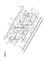
- Fig. 2 is a perspective view illustrating the conveyance system depicted in Fig. 1 .
- Fig. 3 is a block diagram illustrating a system configuration of the conveyance system.
- a conveyance system 100 depicted in Figs. 1 to 3 is provided in a clean room in which semiconductor devices are manufactured.
- the conveyance system 100 includes storage racks 20 that store therein objects 10 to be conveyed, a stacker crane 30, vehicles (overhead carriers) 40, and a controller (control means) 50.
- semiconductor manufacturing devices 60 and 62 are arranged.
- loading ports 64 and 66 each are provided for carrying the objects 10 into and out of the semiconductor manufacturing devices 60 and 62.
- the conveyance system 100 further includes a manufacturing execution system (MES) 110 and a material control system (MCS) 120.
- the MCS 120 is a conveyance instruction device that provides instructions by preparing a conveyance schedule for the objects 10 on the basis of a semiconductor manufacturing schedule and sending a conveyance command based on this conveyance schedule to the controller 50 to which the stacker crane 30 and vehicles 40 are connected.
- the MCS 120 is a system that is provided between an interprocess conveyance facility such as the controller 50 and the MES 110 and has a function of transmitting various instructions from the MES 110 to the controller 50 at appropriate timings and compiling reports from the controller 50 to transmit them to the MES 110.
- the MES 110 is an integrated manufacturing information system that manages various kinds of information at the plant site in an integrated manner and performs information management for the MCS 120 and the semiconductor manufacturing devices 60 and 62.
- the objects 10 are cassettes (what are called front opening unified pods (FOUPs)) each accommodating a plurality of semiconductor wafers.
- An upper surface 10a of each object 10 is provided with a flange portion 10b that is held by a gripper 44 of each vehicle 40 described later.
- a removable lid (not depicted) is attached for semiconductor wafers to be taken in and out.
- identification information that can be uniquely identified is imparted.
- an ID tag T to which the identification information is imparted is attached to each object 10.
- the ID tag T is arranged on a front surface 10d (surface opposite to the side 10c to which the lid is attached) of each object 10.
- the identification information that is imparted to each object 10 is not limited to the ID tag T, and may be a bar code, for example.
- the storage racks 20 are racks that temporarily store therein the objects 10.
- the storage racks 20 are arranged near the semiconductor manufacturing devices 60 and 62.
- the storage racks 20 are arranged with the loading ports 64 and 66 of the semiconductor manufacturing devices 60 and 62 interposed therebetween.
- a plurality (herein, three rows in the height direction) of placement shelves 22 on which the objects 10 are placed are provided.
- pins 24 are provided that protrude upward from the upper surface thereof.
- the pins 24 engage with positioning holes (not depicted) provided to the lower surface of each object 10. With these pins 24, the objects 10 are positioned in the storage rack 20.
- a gap is provided below the lower surface of each object 10 so that transfer arms 39c (described later) of the stacker crane 30 can be inserted into the gap.
- each object 10 is placed so that the front surface 10d thereof faces the stacker crane 30. Accordingly, each object 10 is arranged on one of the placement shelves 22 in such a manner that the ID tag T attached to the front surface 10d faces the stacker crane 30.
- the number and positions of the storage racks 20 to be installed are appropriately determined based on positions and the number of the installed semiconductor manufacturing devices 60 and 62 and the structure of the clean room.
- the storage racks 20 may be suspended from a ceiling, or may be fixed on a floor with supporting members, for example, interposed therebetween.
- the stacker crane 30 includes a traveling truck 32 that travels along rails R1 in the clean room, two support post devices 34 that are installed upright on the traveling truck 32, an elevating platform 36 that is provided in a vertically movable manner with respect to the support post devices 34, a transfer device 38 that is installed on the elevating platform 36, and an ID tag reader (identification-information acquisition means, see Fig. 1 ) R.
- the stacker crane 30 also includes a turntable (not depicted), for example, installed on the elevating platform 36.
- the stacker crane 30 travels straight along the rails R1 constructed in the clean room. Between the semiconductor manufacturing devices 60 and 62 that are arranged facing each other, the rails R1 are constructed in the direction orthogonal to this facing direction. In other words, the stacker crane 30 is provided so as to be a movable in the direction that is substantially orthogonal to the facing direction of the semiconductor manufacturing devices 60 and 62.
- the facing herein does not necessarily have to indicate that the semiconductor manufacturing devices 60 and 62 completely face each other, and they may be arranged with a certain distance therebetween.
- the transfer device 38 has SCARA arms 39.
- Each SCARA arm 39 includes a base-end arm 39a, a front-end arm 39b, and a transfer arm 39c.
- Upper surfaces of transfer arms 39c constitute a transfer plane on which an object 10 is placed.
- the transfer arms 39c of the SCARA arms 39 move straight in the direction (direction in which each object 10 is taking in and taking out) orthogonal to the traveling direction of the traveling truck 32.
- the ID tag reader R is means for reading the ID tag T of each object 10 to acquire identification information.
- the ID tag reader R which is provided to the transfer device 38, for example, reads the ID tag T attached to the object 10 to acquire the identification information before the object 10 stored in a storage rack 20 is conveyed (before being transferred to a loading port).
- the ID tag reader R outputs the acquired identification information to the controller 50.
- the position where the ID tag reader R is attached is not limited to a particular position as long as the ID tag T of each object 10 can be read from the position.
- the stacker crane 30 operates as described below. Specifically, the stacker crane 30 stops in front of a certain storage rack 20, and takes out a certain one of the objects 10 that is stored in the storage rack 20, using the transfer arms 39c. Subsequently, the stacker crane 30 travels along the rails R1 riding on the traveling truck 32, and transfers the object 10 to the loading port 64 of the semiconductor manufacturing device 60, for example. Alternatively, the stacker crane 30 stops in front of the loading port 66 of the semiconductor manufacturing device 62, for example, and carries out one of the objects 10 that is placed on the loading port 66, using the transfer arms 39c. Subsequently, the stacker crane 30 travels to a destination (e.g., a storage rack 20) along the rails R1 riding on the traveling truck 32 to transfer the object 10.
- a destination e.g., a storage rack 20
- the stacker crane 30 is provided so as to be rotatable by the turntable. Accordingly, the stacker crane 30 moves the SCARA arms 39 toward either of the semiconductor manufacturing device 60 and the semiconductor manufacturing device 62 by appropriately changing its direction with the turntable. In this manner, the stacker crane 30 carries the objects 10 into and out of the respective loading ports 64 and 66 of the semiconductor manufacturing devices 60 and 62 that are arranged facing each other. Such conveying operations of the objects 10 performed by the stacker crane 30 are controlled by the controller 50.
- Fig. 1 only one stacker crane 30 is illustrated, but the stacker crane 30 may be provided singly or in plurality on the rails R1.
- the vehicles 40 each are an overhead hoist transport (OHT) and convey an object 10 along travelling rails (track) R2 suspended from a ceiling portion.
- the travelling rails R2 are installed on the ceiling of the clean room, and are arranged above the loading ports 64 and 66 of the semiconductor manufacturing devices 60 and 62.
- Each vehicle 40 has the gripper 44.
- the gripper 44 holds an object 10 by gripping the flange portion 10b.
- the gripper 44 descends from a certain position when a plurality of belts 46 are synchronously paid out by a hoisting unit (not depicted).
- the gripper 44 also ascends to a certain position when the belts 46 are synchronously taken up by the hoisting unit.
- Each vehicle 40 operates as described below. Specifically, the vehicle 40 conveys an object 10 from a source (e.g., a stocker for objects to be conveyed), stops above the loading port 64 of the semiconductor manufacturing device 60, for example, and lowers the thus conveyed object 10 to place the object 10 on the loading port 64. The vehicle 40 also conveys an object 10 from a source, stops above a certain storage rack 20, and lowers the thus conveyed object 10 to place the object 10 at a certain position of the storage rack 20.
- a source e.g., a stocker for objects to be conveyed
- the vehicle 40 also conveys an object 10 from a source, stops above a certain storage rack 20, and lowers the thus conveyed object 10 to place the object 10 at a certain position of the storage rack 20.
- the vehicle 40 also stops above the loading port 66 of the semiconductor manufacturing device 62, for example, grips an object 10 placed on the loading port 66 with the gripper 44, and raises the object 10 in this gripping state to convey the object 10 to a certain destination.
- the vehicle 40 also stops above a storage rack 20, for example, grips an object 10 stored in the storage rack 20 with the gripper 44, and raises the object 10 in this gripping state to convey the object 10 to a certain destination.
- the controller 50 controls the stacker crane 30 and the vehicles 40.
- the controller 50 can communicate with the ID tag reader R provided to the stacker crane 30.
- the controller 50 receives identification information output from the ID tag reader R of the stacker crane 30 and a conveyance command output from the MCS 120, and determines whether the identification information coincides with identification information contained in the conveyance command.
- the conveyance command contains at least identification information for identifying an object 10 and destination information that indicates a destination of the object 10.
- the controller 50 controls the stacker crane 30 to convey the object 10 to the destination that is indicated by the destination information contained in the conveyance command. Accordingly, the stacker crane 30 transfers the object 10 to a certain destination in response to the conveyance command. If the identification information of the object 10 does not coincide with the identification information in the conveyance command, the controller 50 controls the stacker crane 30 to convey the object 10 to a destination (e.g., a rack that temporarily stores therein the object 10) that is different from the destination in the conveyance command.
- a destination e.g., a rack that temporarily stores therein the object
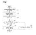
- Fig. 4 is a flowchart illustrating the operations of the conveyance system.
- One example is described below in which an object 10 stored in a storage rack 20 is conveyed to the loading port 64 of the semiconductor manufacturing device 60.
- the stacker crane 30 travels to the front of a certain object 10 in a storage rack 20 (step S01).
- the object 10 is taken out of the storage rack 20 with the transfer arms 39c of the transfer device 38 of the stacker crane 30 (step S02).
- the ID tag T of the object 10 is read by the ID tag reader R (step S03).
- the controller 50 determines whether the identification information of the ID tag T read by the ID tag reader R coincides with identification information contained in the conveyance command (step S04). If it is determined that the identification information of the ID tag T coincides with the identification information contained in the conveyance command, the stacker crane 30 is controlled by the controller 50 to convey the object 10 to the loading port 64 (step S05). If it is not determined that the identification information of the ID tag T coincides with the identification information contained in the conveyance command, the stacker crane 30 is controlled by the controller 50 to convey the object 10 to another certain destination (step S06).
- the storage racks 20 are arranged near the semiconductor manufacturing devices 60 and 62. With these storage racks 20, space for accommodating objects 10 can be secured. In addition, this arrangement of the storage racks 20 near the semiconductor manufacturing devices 60 and 62 enables the objects 10 to be quickly transferred between the storage racks 20 and the loading ports 64 and 66.
- the ID tag T of an object 10 stored in a storage rack 20 is read by the ID tag reader R of the stacker crane 30 and, if the identification information thus read coincides with identification information contained in a conveyance command, the controller 50 controls the stacker crane 30 to convey the object 10 to a destination specified by the conveyance command.
- objects 10 can be identified in the controller 50 that controls the stacker crane 30, and thus processing speed can be improved compared with a conventional system in which, for example, identification information of an object 10 is acquired at a loading port, the identification information is output to the MES 110, and the object 10 is identified by the MES 110.
- the ID tag reader R is provided to the stacker crane 30, the necessity of providing ID tag readers to the storage racks 20 and the loading ports 64 and 66 can be eliminated, whereby the structure can be simplified and the cost can be reduced.
- the vehicles 40 directly carries in and out objects 10 at the loading ports 64 and 66.
- the object 10 is conveyed to and placed on a certain port by a vehicle 40, and later the object 10 is conveyed to a certain loading port by the stacker crane 30. This inevitably requires time to convey the object 10.
- the present embodiment enables objects 10 to be directly conveyed into and out of the loading ports 64 and 66 by the vehicles 40 without the stacker crane 30, a time for temporarily storing the objects 10 and a transfer time by the stacker crane 30 can be shortened.
- the conveyance times of the objects 10 can be shortened, and the objects 10 can be quickly conveyed.
- the flexibility of conveyance of the objects 10 can be improved.
- the present embodiment can improve the efficiency of conveying the objects 10.
- the upper portions of the storage racks 20 are open. This enables the vehicles 40 to take in and out the objects 10 at the storage racks 20.
- the storage racks 20 can function as ports for passing the objects 10 between the stacker crane 30 and the vehicles 40. This enables the objects 10 to be more efficiently conveyed.
- the present invention is not limited to the above-described embodiment.
- a configuration has been described as one example in which two semiconductor manufacturing devices 60 and 62 are arranged, but the installation number of semiconductor manufacturing devices, for example, may be appropriately determined depending on the design of a semiconductor manufacturing plant.
- An interbay stocker may be provided that temporarily stores therein the objects 10.
- the stacker crane 30 and the vehicles 40 can access the interbay stocker.
Landscapes
- Engineering & Computer Science (AREA)
- Mechanical Engineering (AREA)
- General Engineering & Computer Science (AREA)
- Manufacturing & Machinery (AREA)
- Quality & Reliability (AREA)
- Physics & Mathematics (AREA)
- General Physics & Mathematics (AREA)
- Automation & Control Theory (AREA)
- Warehouses Or Storage Devices (AREA)
- Container, Conveyance, Adherence, Positioning, Of Wafer (AREA)
Abstract
Description
- The present invention relates to a conveyance system.
- As a conventional conveyance system, a conveyance system described in Patent Literature 1, for example, is known. The conveyance system described in Patent Literature 1 includes: a carrier that conveys a cassette on which an ID tag is attached, the carrier equipped with an ID reader that identifies the ID tag; and a station on which the cassette is placed, and the conveyance system controls conveyance of the cassette on the basis of the ID tag attached on the cassette.
- [Patent Literature 1] Japanese Patent Application Laid-Open Publication No.
2002-179203 - As in the conveyance system described above in Patent Literature 1, controlling the cassette on the basis of the ID tag is effective from the viewpoint of accuracy and efficiency of conveyance. In recent years, faster processing in manufacturing semiconductor devices has been promoted, and shortening of a takt time in a semiconductor manufacturing device has been required. At the same time, further speeding up of the time for conveying semiconductor wafers between processes has been required. In addition, recent upsizing of semiconductor wafers has increased the size of a front opening unified pod (FOUP, also referred to as a cassette) as a container that accommodates the semiconductor wafers. Accordingly, in a semiconductor manufacturing plant, more space is required for accommodating the FOUP than ever before, but securing space for accommodating the FOUP within a limited space is not easy.
- The present invention aims to provide a conveyance system that can secure space for accommodating objects to be conveyed and also can accurately and efficiently convey the objects.
- A conveyance system according to one aspect of the present invention is a conveyance system that conveys an object to be conveyed to which identification information that is uniquely identifiable is imparted. The conveyance system includes: a storage rack that is provided near a semiconductor manufacturing device and stores therein the object; a stacker crane that carries the object into the storage rack and also carries the object out of the storage rack; an overhead carrier that travels along a track provided on a ceiling portion and raises and lowers a gripper that grips the object to convey the object; identification-information acquisition means for acquiring the identification information imparted to the object, the identification-information acquisition means being provided to the stacker crane; and control means for, when the identification information acquired by the identification-information acquisition means coincides with identification information contained in a conveyance command for the object, controlling the stacker crane to convey the object to a destination specified in the conveyance command. At least one section of the storage rack allows the gripper of the overhead carrier to take in and out the object.
- In this conveyance system, the storage rack is provided that stores therein an object to be conveyed near the semiconductor manufacturing device. This can secure space for accommodating the object. In the conveyance system, because the storage rack is arranged near the semiconductor manufacturing device, transfer of the object between the storage rack and a loading port can be performed quickly. In the conveyance system, the object can be taken into and out of at least one section of the storage rack by the gripper of the overhead carrier. In this manner, the conveying system is configured such that the overhead carrier can access the storage rack, whereby the storage rack can function as a port for passing the object between the stacker crane and the overhead carrier. This enables the conveyance system to efficiently convey the object. Furthermore, in the conveyance system, when the identification information imparted to the object coincides with the identification information contained in the conveyance command, the stacker crane is controlled to convey the object to the destination specified in the conveyance command. This enables the conveyance system to convey the object accurately to a specified destination. As described above, the conveyance system can secure space for accommodating the object and also can accurately and efficiently convey the object.
- In one embodiment, at a loading port of the semiconductor manufacturing device, the stacker crane and the overhead carrier may be capable of carrying in and out the object. This enables the overhead carrier to carry the object directly into and out of the loading port in the conveyance system. Accordingly, in the conveyance system, a time for temporarily storing the object to pass the object to the stacker crane can be shortened, and a time for transfer by the stacker crane can also be shortened, whereby the object can be quickly conveyed. In the conveyance system, flexibility in transfer of the object can also be improved. Thus, in the conveyance system, the efficiency of conveying the object can be further improved.
- According to the present invention, space for accommodating an object to be conveyed can be secured, and also the object can be accurately and efficiently conveyed.
-
-
Fig. 1 is a plan view of a conveyance system according to one embodiment. -
Fig. 2 is a perspective view illustrating the conveyance system depicted inFig. 1 . -
Fig. 3 is a block diagram illustrating a system configuration of the conveyance system. -
Fig. 4 is a flowchart illustrating operations of the conveyance system. - Preferred embodiments of the present invention will be described hereinafter in detail with reference to the drawings. In the drawings, like reference signs indicate like or corresponding components, and duplicate description is omitted.
-
Fig. 1 is a plan view of a conveyance system according to one embodiment.Fig. 2 is a perspective view illustrating the conveyance system depicted inFig. 1 .Fig. 3 is a block diagram illustrating a system configuration of the conveyance system. - A
conveyance system 100 depicted inFigs. 1 to 3 is provided in a clean room in which semiconductor devices are manufactured. Theconveyance system 100 includesstorage racks 20 that store thereinobjects 10 to be conveyed, astacker crane 30, vehicles (overhead carriers) 40, and a controller (control means) 50. In the clean room,semiconductor manufacturing devices semiconductor manufacturing devices loading ports objects 10 into and out of thesemiconductor manufacturing devices - The
conveyance system 100 further includes a manufacturing execution system (MES) 110 and a material control system (MCS) 120. The MCS 120 is a conveyance instruction device that provides instructions by preparing a conveyance schedule for theobjects 10 on the basis of a semiconductor manufacturing schedule and sending a conveyance command based on this conveyance schedule to thecontroller 50 to which thestacker crane 30 andvehicles 40 are connected. As depicted inFig. 3 , theMCS 120 is a system that is provided between an interprocess conveyance facility such as thecontroller 50 and theMES 110 and has a function of transmitting various instructions from theMES 110 to thecontroller 50 at appropriate timings and compiling reports from thecontroller 50 to transmit them to theMES 110. The MES 110 is an integrated manufacturing information system that manages various kinds of information at the plant site in an integrated manner and performs information management for theMCS 120 and thesemiconductor manufacturing devices - The
objects 10 are cassettes (what are called front opening unified pods (FOUPs)) each accommodating a plurality of semiconductor wafers. Anupper surface 10a of eachobject 10 is provided with aflange portion 10b that is held by a gripper 44 of eachvehicle 40 described later. To a side (rear surface) 10c of eachobject 10, a removable lid (not depicted) is attached for semiconductor wafers to be taken in and out. - To each
object 10, identification information that can be uniquely identified is imparted. In the present embodiment, an ID tag T to which the identification information is imparted is attached to eachobject 10. The ID tag T is arranged on afront surface 10d (surface opposite to theside 10c to which the lid is attached) of eachobject 10. The identification information that is imparted to eachobject 10 is not limited to the ID tag T, and may be a bar code, for example. - The
storage racks 20 are racks that temporarily store therein theobjects 10. Thestorage racks 20 are arranged near thesemiconductor manufacturing devices storage racks 20 are arranged with theloading ports semiconductor manufacturing devices storage rack 20, a plurality (herein, three rows in the height direction) ofplacement shelves 22 on which theobjects 10 are placed are provided. On eachplacement shelf 22,pins 24 are provided that protrude upward from the upper surface thereof. Thepins 24 engage with positioning holes (not depicted) provided to the lower surface of eachobject 10. With thesepins 24, theobjects 10 are positioned in thestorage rack 20. In eachplacement shelf 22, a gap is provided below the lower surface of eachobject 10 so thattransfer arms 39c (described later) of thestacker crane 30 can be inserted into the gap. - Upper portions of the storage racks 20 are open. In other words, the
objects 10 can be taken into and out of at least one section of eachstorage rack 20 by the gripper 44 of eachvehicle 40. In the storage racks 20, eachobject 10 is placed so that thefront surface 10d thereof faces thestacker crane 30. Accordingly, eachobject 10 is arranged on one of theplacement shelves 22 in such a manner that the ID tag T attached to thefront surface 10d faces thestacker crane 30. The number and positions of the storage racks 20 to be installed are appropriately determined based on positions and the number of the installedsemiconductor manufacturing devices - The
stacker crane 30 includes a travelingtruck 32 that travels along rails R1 in the clean room, twosupport post devices 34 that are installed upright on the travelingtruck 32, an elevatingplatform 36 that is provided in a vertically movable manner with respect to thesupport post devices 34, atransfer device 38 that is installed on the elevatingplatform 36, and an ID tag reader (identification-information acquisition means, seeFig. 1 ) R. Thestacker crane 30 also includes a turntable (not depicted), for example, installed on the elevatingplatform 36. - The
stacker crane 30 travels straight along the rails R1 constructed in the clean room. Between thesemiconductor manufacturing devices stacker crane 30 is provided so as to be a movable in the direction that is substantially orthogonal to the facing direction of thesemiconductor manufacturing devices semiconductor manufacturing devices - The
transfer device 38 hasSCARA arms 39. EachSCARA arm 39 includes a base-end arm 39a, a front-end arm 39b, and atransfer arm 39c. Upper surfaces oftransfer arms 39c constitute a transfer plane on which anobject 10 is placed. Thetransfer arms 39c of theSCARA arms 39 move straight in the direction (direction in which each object 10 is taking in and taking out) orthogonal to the traveling direction of the travelingtruck 32. - The ID tag reader R is means for reading the ID tag T of each
object 10 to acquire identification information. The ID tag reader R, which is provided to thetransfer device 38, for example, reads the ID tag T attached to theobject 10 to acquire the identification information before theobject 10 stored in astorage rack 20 is conveyed (before being transferred to a loading port). The ID tag reader R outputs the acquired identification information to thecontroller 50. The position where the ID tag reader R is attached is not limited to a particular position as long as the ID tag T of eachobject 10 can be read from the position. - The
stacker crane 30 operates as described below. Specifically, thestacker crane 30 stops in front of acertain storage rack 20, and takes out a certain one of theobjects 10 that is stored in thestorage rack 20, using thetransfer arms 39c. Subsequently, thestacker crane 30 travels along the rails R1 riding on the travelingtruck 32, and transfers theobject 10 to theloading port 64 of thesemiconductor manufacturing device 60, for example. Alternatively, thestacker crane 30 stops in front of theloading port 66 of thesemiconductor manufacturing device 62, for example, and carries out one of theobjects 10 that is placed on theloading port 66, using thetransfer arms 39c. Subsequently, thestacker crane 30 travels to a destination (e.g., a storage rack 20) along the rails R1 riding on the travelingtruck 32 to transfer theobject 10. - The
stacker crane 30 is provided so as to be rotatable by the turntable. Accordingly, thestacker crane 30 moves theSCARA arms 39 toward either of thesemiconductor manufacturing device 60 and thesemiconductor manufacturing device 62 by appropriately changing its direction with the turntable. In this manner, thestacker crane 30 carries theobjects 10 into and out of therespective loading ports semiconductor manufacturing devices objects 10 performed by thestacker crane 30 are controlled by thecontroller 50. - In
Fig. 1 , only onestacker crane 30 is illustrated, but thestacker crane 30 may be provided singly or in plurality on the rails R1. - The
vehicles 40 each are an overhead hoist transport (OHT) and convey anobject 10 along travelling rails (track) R2 suspended from a ceiling portion. The travelling rails R2 are installed on the ceiling of the clean room, and are arranged above theloading ports semiconductor manufacturing devices - Each
vehicle 40 has the gripper 44. The gripper 44 holds anobject 10 by gripping theflange portion 10b. The gripper 44 descends from a certain position when a plurality ofbelts 46 are synchronously paid out by a hoisting unit (not depicted). The gripper 44 also ascends to a certain position when thebelts 46 are synchronously taken up by the hoisting unit. - Each
vehicle 40 operates as described below. Specifically, thevehicle 40 conveys anobject 10 from a source (e.g., a stocker for objects to be conveyed), stops above theloading port 64 of thesemiconductor manufacturing device 60, for example, and lowers the thus conveyedobject 10 to place theobject 10 on theloading port 64. Thevehicle 40 also conveys anobject 10 from a source, stops above acertain storage rack 20, and lowers the thus conveyedobject 10 to place theobject 10 at a certain position of thestorage rack 20. - The
vehicle 40 also stops above theloading port 66 of thesemiconductor manufacturing device 62, for example, grips anobject 10 placed on theloading port 66 with the gripper 44, and raises theobject 10 in this gripping state to convey theobject 10 to a certain destination. Thevehicle 40 also stops above astorage rack 20, for example, grips anobject 10 stored in thestorage rack 20 with the gripper 44, and raises theobject 10 in this gripping state to convey theobject 10 to a certain destination. - The
controller 50 controls thestacker crane 30 and thevehicles 40. Thecontroller 50 can communicate with the ID tag reader R provided to thestacker crane 30. Thecontroller 50 receives identification information output from the ID tag reader R of thestacker crane 30 and a conveyance command output from theMCS 120, and determines whether the identification information coincides with identification information contained in the conveyance command. The conveyance command contains at least identification information for identifying anobject 10 and destination information that indicates a destination of theobject 10. - If the identification information of the
object 10 coincides with the identification information in the conveyance command, thecontroller 50 controls thestacker crane 30 to convey theobject 10 to the destination that is indicated by the destination information contained in the conveyance command. Accordingly, thestacker crane 30 transfers theobject 10 to a certain destination in response to the conveyance command. If the identification information of theobject 10 does not coincide with the identification information in the conveyance command, thecontroller 50 controls thestacker crane 30 to convey theobject 10 to a destination (e.g., a rack that temporarily stores therein the object 10) that is different from the destination in the conveyance command. - Operations of the
conveyance system 100 will be described hereinafter with reference toFig. 4. Fig. 4 is a flowchart illustrating the operations of the conveyance system. One example is described below in which anobject 10 stored in astorage rack 20 is conveyed to theloading port 64 of thesemiconductor manufacturing device 60. - As depicted in
Fig. 4 , controlled by thecontroller 50 on the basis of a conveyance command, thestacker crane 30 travels to the front of acertain object 10 in a storage rack 20 (step S01). Next, theobject 10 is taken out of thestorage rack 20 with thetransfer arms 39c of thetransfer device 38 of the stacker crane 30 (step S02). At this time, the ID tag T of theobject 10 is read by the ID tag reader R (step S03). - Subsequently, the
controller 50 determines whether the identification information of the ID tag T read by the ID tag reader R coincides with identification information contained in the conveyance command (step S04). If it is determined that the identification information of the ID tag T coincides with the identification information contained in the conveyance command, thestacker crane 30 is controlled by thecontroller 50 to convey theobject 10 to the loading port 64 (step S05). If it is not determined that the identification information of the ID tag T coincides with the identification information contained in the conveyance command, thestacker crane 30 is controlled by thecontroller 50 to convey theobject 10 to another certain destination (step S06). - As described above, in the present embodiment, the storage racks 20 are arranged near the
semiconductor manufacturing devices storage racks 20, space foraccommodating objects 10 can be secured. In addition, this arrangement of the storage racks 20 near thesemiconductor manufacturing devices objects 10 to be quickly transferred between the storage racks 20 and theloading ports - Furthermore, in the present embodiment, the ID tag T of an
object 10 stored in astorage rack 20 is read by the ID tag reader R of thestacker crane 30 and, if the identification information thus read coincides with identification information contained in a conveyance command, thecontroller 50 controls thestacker crane 30 to convey theobject 10 to a destination specified by the conveyance command. In this manner, in the present embodiment, objects 10 can be identified in thecontroller 50 that controls thestacker crane 30, and thus processing speed can be improved compared with a conventional system in which, for example, identification information of anobject 10 is acquired at a loading port, the identification information is output to theMES 110, and theobject 10 is identified by theMES 110. Thus, objects 10 can be quickly and accurately conveyed to destinations. In addition, because the ID tag reader R is provided to thestacker crane 30, the necessity of providing ID tag readers to the storage racks 20 and theloading ports - In the present embodiment, the
vehicles 40 directly carries in and outobjects 10 at theloading ports object 10 for an urgent lot requiring immediate processing is conveyed, conventionally, theobject 10 is conveyed to and placed on a certain port by avehicle 40, and later theobject 10 is conveyed to a certain loading port by thestacker crane 30. This inevitably requires time to convey theobject 10. - In contrast, because the present embodiment enables
objects 10 to be directly conveyed into and out of theloading ports vehicles 40 without thestacker crane 30, a time for temporarily storing theobjects 10 and a transfer time by thestacker crane 30 can be shortened. Thus, the conveyance times of theobjects 10 can be shortened, and theobjects 10 can be quickly conveyed. In addition, the flexibility of conveyance of theobjects 10 can be improved. As described above, the present embodiment can improve the efficiency of conveying theobjects 10. - In the present embodiment, the upper portions of the storage racks 20 are open. This enables the
vehicles 40 to take in and out theobjects 10 at the storage racks 20. Thus, the storage racks 20 can function as ports for passing theobjects 10 between thestacker crane 30 and thevehicles 40. This enables theobjects 10 to be more efficiently conveyed. - From another viewpoint, the present embodiment provides a conveyance system that conveys an object to be conveyed to which identification information that is uniquely identifiable is imparted. The conveyance system includes: a storage rack that is provided near a semiconductor manufacturing device and stores therein the object; a stacker crane that carries the object into the storage rack and also carries the object out of the storage rack; an overhead carrier that travels along a track provided on a ceiling portion and raises and lowers a gripper that grips the object to convey the object; an ID tag reader that is provided to the stacker crane and acquires the identification information imparted to the object; and a controller that, when the identification information acquired by the ID tag reader coincides with identification information contained in a conveyance command for the object, controls the stacker crane to convey the object to a destination specified in the conveyance command. At least one section of the storage rack allows the gripper of the overhead carrier to take in and out the object.
- The present invention is not limited to the above-described embodiment. For example, in the above-described embodiment, a configuration has been described as one example in which two
semiconductor manufacturing devices objects 10. Thestacker crane 30 and thevehicles 40 can access the interbay stocker. - 100... conveyance system, 10... object (to be conveyed), 20... storage rack, 30... stacker crane, 40... vehicle (overhead carrier), 44... gripper, 50... controller (control means), 60, 62... semiconductor manufacturing device, 64, 66... loading port, R... ID tag reader (identification-information acquisition means), T... ID tag (identification information)
Claims (2)
- A conveyance system that conveys an object to be conveyed to which identification information that is uniquely identifiable is imparted, the conveyance system comprising:a storage rack that is provided near a semiconductor manufacturing device and stores therein the object;a stacker crane that carries the object into the storage rack and also carries the object out of the storage rack;an overhead carrier that travels along a track provided on a ceiling portion and raises and lowers a gripper that grips the object to convey the object;identification-information acquisition means for acquiring the identification information imparted to the object, the identification-information acquisition means being provided to the stacker crane; andcontrol means for, when the identification information acquired by the identification-information acquisition means coincides with identification information contained in a conveyance command for the object, controlling the stacker crane to convey the object to a destination specified in the conveyance command, whereinat least one section of the storage rack allows the gripper of the overhead carrier to take in and out the object.
- The conveyance system according to claim 1, wherein at a loading port of the semiconductor manufacturing device, the stacker crane and the overhead carrier are capable of carrying in and out the object.
Applications Claiming Priority (2)
| Application Number | Priority Date | Filing Date | Title |
|---|---|---|---|
| JP2012086392 | 2012-04-05 | ||
| PCT/JP2013/056346 WO2013150859A1 (en) | 2012-04-05 | 2013-03-07 | Conveyance system |
Publications (3)
| Publication Number | Publication Date |
|---|---|
| EP2835325A1 true EP2835325A1 (en) | 2015-02-11 |
| EP2835325A4 EP2835325A4 (en) | 2016-01-06 |
| EP2835325B1 EP2835325B1 (en) | 2018-09-05 |
Family
ID=49300356
Family Applications (1)
| Application Number | Title | Priority Date | Filing Date |
|---|---|---|---|
| EP13772486.0A Active EP2835325B1 (en) | 2012-04-05 | 2013-03-07 | Conveyance system |
Country Status (7)
| Country | Link |
|---|---|
| US (1) | US9845193B2 (en) |
| EP (1) | EP2835325B1 (en) |
| JP (1) | JP5880693B2 (en) |
| KR (1) | KR101661633B1 (en) |
| CN (1) | CN104245541B (en) |
| TW (1) | TWI522295B (en) |
| WO (1) | WO2013150859A1 (en) |
Cited By (2)
| Publication number | Priority date | Publication date | Assignee | Title |
|---|---|---|---|---|
| DE202018102001U1 (en) * | 2018-04-12 | 2019-07-15 | Aberu Gmbh | Device for moving load carriers, adapters for receiving load carriers and transport trolleys for picking up and transporting load carriers |
| EP3476772A4 (en) * | 2016-06-27 | 2020-03-04 | Murata Machinery, Ltd. | TRANSPORT SYSTEM |
Families Citing this family (17)
| Publication number | Priority date | Publication date | Assignee | Title |
|---|---|---|---|---|
| EP2947030A1 (en) * | 2014-05-23 | 2015-11-25 | Pesmel Group Oy | Stacker crane with two load handling units and method to use such rack feeder in a warehouse |
| KR101676718B1 (en) * | 2015-03-12 | 2016-11-17 | 주식회사 에스에프에이 | Stocker |
| CN108352348B (en) * | 2015-12-08 | 2022-05-10 | 村田机械株式会社 | Conveying system and conveying method |
| CN105858036A (en) * | 2016-06-12 | 2016-08-17 | 广州威能机电有限公司 | Material access system and control method |
| JP6589847B2 (en) * | 2016-12-26 | 2019-10-16 | 株式会社ダイフク | Material loading equipment |
| JP6849065B2 (en) * | 2017-06-30 | 2021-03-24 | 村田機械株式会社 | Transport system and transport method |
| JP6965646B2 (en) * | 2017-09-06 | 2021-11-10 | 株式会社ダイフク | Transport vehicle and transport equipment |
| JP6854498B2 (en) * | 2018-01-10 | 2021-04-07 | 村田機械株式会社 | Transport system control method, transport system and management equipment |
| WO2019181241A1 (en) | 2018-03-22 | 2019-09-26 | 村田機械株式会社 | Stocker system |
| KR101973503B1 (en) * | 2018-07-10 | 2019-04-29 | (주)에스티아이 | Akutomatic transfer apparatus of chemical container and the method thereof |
| JP7529039B2 (en) * | 2020-11-12 | 2024-08-06 | 村田機械株式会社 | Storage shelf |
| JP7559620B2 (en) * | 2021-03-02 | 2024-10-02 | 村田機械株式会社 | Transport System |
| CN114408452B (en) * | 2022-01-27 | 2023-08-04 | 赛美特科技有限公司 | Wafer conveying method and device, electronic equipment and storage medium |
| CN115009737A (en) * | 2022-05-31 | 2022-09-06 | 江苏木盟智能科技有限公司 | Multi-scene intelligent carrying method and system, storage medium and intelligent carrying robot |
| JP7838431B2 (en) * | 2022-08-08 | 2026-04-01 | 株式会社ダイフク | A transport system, a method for controlling the transport system, a control program, and a recording medium. |
| CN115818086B (en) * | 2022-12-14 | 2023-08-08 | 弥费科技(上海)股份有限公司 | Storage scheduling system and method for docking wafer storage warehouse with sky train entrance |
| JP2025009152A (en) * | 2023-07-07 | 2025-01-20 | 株式会社ディスコ | Transport vehicle |
Family Cites Families (21)
| Publication number | Priority date | Publication date | Assignee | Title |
|---|---|---|---|---|
| JP3669057B2 (en) * | 1996-06-03 | 2005-07-06 | アシスト シンコー株式会社 | Transport system to stocker |
| JP3447724B2 (en) | 1997-08-22 | 2003-09-16 | 富士重工業株式会社 | Garbage loading device for garbage trucks |
| JP2000118607A (en) * | 1998-10-12 | 2000-04-25 | Murata Mach Ltd | Carrier system |
| JP2002060011A (en) * | 2000-08-11 | 2002-02-26 | Murata Mach Ltd | Automated warehouse |
| JP2003188229A (en) * | 2001-12-18 | 2003-07-04 | Hitachi Kasado Eng Co Ltd | Wafer manufacturing system and wafer manufacturing method |
| JP3991852B2 (en) | 2002-12-09 | 2007-10-17 | 村田機械株式会社 | Ceiling carrier system |
| AU2003242171A1 (en) * | 2003-06-05 | 2005-01-04 | Hirata Corporation | Assembling system, assembling unit, layout arranging system and layout arranging method |
| JP2006096427A (en) | 2004-09-28 | 2006-04-13 | Murata Mach Ltd | Article storage facility |
| TW200621600A (en) * | 2004-12-02 | 2006-07-01 | Murata Machinery Ltd | Automatic warehouse |
| JP2007106528A (en) * | 2005-10-12 | 2007-04-26 | Hitachi Plant Technologies Ltd | Hierarchical entry / exit stocker system |
| JP2007186319A (en) * | 2006-01-16 | 2007-07-26 | Murata Mach Ltd | Transport system |
| US8043039B2 (en) | 2007-09-20 | 2011-10-25 | Tokyo Electron Limited | Substrate treatment apparatus |
| JP4887332B2 (en) * | 2007-09-20 | 2012-02-29 | 東京エレクトロン株式会社 | Substrate processing equipment |
| JP4688000B2 (en) * | 2008-02-06 | 2011-05-25 | 株式会社ダイフク | Goods storage equipment |
| JP4555881B2 (en) * | 2008-03-18 | 2010-10-06 | 株式会社日立国際電気 | Substrate processing apparatus and display method |
| JP5493314B2 (en) | 2008-09-05 | 2014-05-14 | 村田機械株式会社 | Containment transfer system |
| JP5284808B2 (en) * | 2009-01-26 | 2013-09-11 | 株式会社Sokudo | Stocker apparatus and substrate processing apparatus |
| JP5267653B2 (en) * | 2009-03-03 | 2013-08-21 | 村田機械株式会社 | Transport system |
| JP5321913B2 (en) | 2009-12-07 | 2013-10-23 | 株式会社ダイフク | Goods storage facility |
| KR101414772B1 (en) * | 2010-04-02 | 2014-07-03 | 무라다기카이가부시끼가이샤 | Automated warehouse |
| WO2011148412A1 (en) * | 2010-05-26 | 2011-12-01 | ムラテックオートメーション株式会社 | Automated warehouse provided in front of device |
-
2013
- 2013-03-07 JP JP2014509092A patent/JP5880693B2/en active Active
- 2013-03-07 US US14/390,420 patent/US9845193B2/en active Active
- 2013-03-07 CN CN201380016960.0A patent/CN104245541B/en active Active
- 2013-03-07 WO PCT/JP2013/056346 patent/WO2013150859A1/en not_active Ceased
- 2013-03-07 KR KR1020147026973A patent/KR101661633B1/en active Active
- 2013-03-07 EP EP13772486.0A patent/EP2835325B1/en active Active
- 2013-04-03 TW TW102112071A patent/TWI522295B/en active
Cited By (2)
| Publication number | Priority date | Publication date | Assignee | Title |
|---|---|---|---|---|
| EP3476772A4 (en) * | 2016-06-27 | 2020-03-04 | Murata Machinery, Ltd. | TRANSPORT SYSTEM |
| DE202018102001U1 (en) * | 2018-04-12 | 2019-07-15 | Aberu Gmbh | Device for moving load carriers, adapters for receiving load carriers and transport trolleys for picking up and transporting load carriers |
Also Published As
| Publication number | Publication date |
|---|---|
| TW201402428A (en) | 2014-01-16 |
| EP2835325B1 (en) | 2018-09-05 |
| US20150045937A1 (en) | 2015-02-12 |
| US9845193B2 (en) | 2017-12-19 |
| CN104245541A (en) | 2014-12-24 |
| KR101661633B1 (en) | 2016-09-30 |
| WO2013150859A1 (en) | 2013-10-10 |
| JPWO2013150859A1 (en) | 2015-12-17 |
| CN104245541B (en) | 2016-03-23 |
| EP2835325A4 (en) | 2016-01-06 |
| JP5880693B2 (en) | 2016-03-09 |
| KR20140137396A (en) | 2014-12-02 |
| TWI522295B (en) | 2016-02-21 |
Similar Documents
| Publication | Publication Date | Title |
|---|---|---|
| EP2835325B1 (en) | Conveyance system | |
| US10913601B2 (en) | Temporary storage system | |
| US10497594B2 (en) | Conveyance system | |
| KR101804352B1 (en) | Storage warehouse | |
| KR102206058B1 (en) | Conveyance system | |
| US9123013B2 (en) | Container conveying carriage and conveying system including a container conveying carriage | |
| US10947041B2 (en) | Transport system and transport method | |
| EP3636562B1 (en) | Floor-to-floor transport system and floor-to-floor transport method | |
| EP3647229A1 (en) | Conveying system and conveying method | |
| EP3159923A1 (en) | Carrier buffering device and buffering method | |
| EP3508442B1 (en) | Automated warehouse | |
| KR20090026099A (en) | Warehouse, Return Systems, and Warehouse Sets | |
| WO2013150841A1 (en) | Conveyance system | |
| JP2013214654A (en) | Conveyance system | |
| WO2019026484A1 (en) | Conveying system and conveying method | |
| WO2011148412A1 (en) | Automated warehouse provided in front of device |
Legal Events
| Date | Code | Title | Description |
|---|---|---|---|
| PUAI | Public reference made under article 153(3) epc to a published international application that has entered the european phase |
Free format text: ORIGINAL CODE: 0009012 |
|
| 17P | Request for examination filed |
Effective date: 20141027 |
|
| AK | Designated contracting states |
Kind code of ref document: A1 Designated state(s): AL AT BE BG CH CY CZ DE DK EE ES FI FR GB GR HR HU IE IS IT LI LT LU LV MC MK MT NL NO PL PT RO RS SE SI SK SM TR |
|
| AX | Request for extension of the european patent |
Extension state: BA ME |
|
| DAX | Request for extension of the european patent (deleted) | ||
| RA4 | Supplementary search report drawn up and despatched (corrected) |
Effective date: 20151208 |
|
| RIC1 | Information provided on ipc code assigned before grant |
Ipc: B65G 1/137 20060101ALI20151202BHEP Ipc: H01L 21/677 20060101ALI20151202BHEP Ipc: B65G 1/04 20060101AFI20151202BHEP Ipc: B65G 1/00 20060101ALI20151202BHEP Ipc: B65G 35/08 20060101ALI20151202BHEP Ipc: B65G 49/07 20060101ALI20151202BHEP |
|
| STAA | Information on the status of an ep patent application or granted ep patent |
Free format text: STATUS: EXAMINATION IS IN PROGRESS |
|
| 17Q | First examination report despatched |
Effective date: 20161212 |
|
| GRAP | Despatch of communication of intention to grant a patent |
Free format text: ORIGINAL CODE: EPIDOSNIGR1 |
|
| STAA | Information on the status of an ep patent application or granted ep patent |
Free format text: STATUS: GRANT OF PATENT IS INTENDED |
|
| INTG | Intention to grant announced |
Effective date: 20180321 |
|
| GRAS | Grant fee paid |
Free format text: ORIGINAL CODE: EPIDOSNIGR3 |
|
| GRAA | (expected) grant |
Free format text: ORIGINAL CODE: 0009210 |
|
| STAA | Information on the status of an ep patent application or granted ep patent |
Free format text: STATUS: THE PATENT HAS BEEN GRANTED |
|
| AK | Designated contracting states |
Kind code of ref document: B1 Designated state(s): AL AT BE BG CH CY CZ DE DK EE ES FI FR GB GR HR HU IE IS IT LI LT LU LV MC MK MT NL NO PL PT RO RS SE SI SK SM TR |
|
| REG | Reference to a national code |
Ref country code: GB Ref legal event code: FG4D |
|
| REG | Reference to a national code |
Ref country code: CH Ref legal event code: EP |
|
| REG | Reference to a national code |
Ref country code: AT Ref legal event code: REF Ref document number: 1037531 Country of ref document: AT Kind code of ref document: T Effective date: 20180915 |
|
| REG | Reference to a national code |
Ref country code: IE Ref legal event code: FG4D |
|
| REG | Reference to a national code |
Ref country code: DE Ref legal event code: R096 Ref document number: 602013043196 Country of ref document: DE |
|
| REG | Reference to a national code |
Ref country code: NL Ref legal event code: MP Effective date: 20180905 |
|
| REG | Reference to a national code |
Ref country code: LT Ref legal event code: MG4D |
|
| PG25 | Lapsed in a contracting state [announced via postgrant information from national office to epo] |
Ref country code: FI Free format text: LAPSE BECAUSE OF FAILURE TO SUBMIT A TRANSLATION OF THE DESCRIPTION OR TO PAY THE FEE WITHIN THE PRESCRIBED TIME-LIMIT Effective date: 20180905 Ref country code: RS Free format text: LAPSE BECAUSE OF FAILURE TO SUBMIT A TRANSLATION OF THE DESCRIPTION OR TO PAY THE FEE WITHIN THE PRESCRIBED TIME-LIMIT Effective date: 20180905 Ref country code: NO Free format text: LAPSE BECAUSE OF FAILURE TO SUBMIT A TRANSLATION OF THE DESCRIPTION OR TO PAY THE FEE WITHIN THE PRESCRIBED TIME-LIMIT Effective date: 20181205 Ref country code: GR Free format text: LAPSE BECAUSE OF FAILURE TO SUBMIT A TRANSLATION OF THE DESCRIPTION OR TO PAY THE FEE WITHIN THE PRESCRIBED TIME-LIMIT Effective date: 20181206 Ref country code: SE Free format text: LAPSE BECAUSE OF FAILURE TO SUBMIT A TRANSLATION OF THE DESCRIPTION OR TO PAY THE FEE WITHIN THE PRESCRIBED TIME-LIMIT Effective date: 20180905 Ref country code: BG Free format text: LAPSE BECAUSE OF FAILURE TO SUBMIT A TRANSLATION OF THE DESCRIPTION OR TO PAY THE FEE WITHIN THE PRESCRIBED TIME-LIMIT Effective date: 20181205 Ref country code: LT Free format text: LAPSE BECAUSE OF FAILURE TO SUBMIT A TRANSLATION OF THE DESCRIPTION OR TO PAY THE FEE WITHIN THE PRESCRIBED TIME-LIMIT Effective date: 20180905 |
|
| REG | Reference to a national code |
Ref country code: AT Ref legal event code: MK05 Ref document number: 1037531 Country of ref document: AT Kind code of ref document: T Effective date: 20180905 |
|
| PG25 | Lapsed in a contracting state [announced via postgrant information from national office to epo] |
Ref country code: HR Free format text: LAPSE BECAUSE OF FAILURE TO SUBMIT A TRANSLATION OF THE DESCRIPTION OR TO PAY THE FEE WITHIN THE PRESCRIBED TIME-LIMIT Effective date: 20180905 Ref country code: LV Free format text: LAPSE BECAUSE OF FAILURE TO SUBMIT A TRANSLATION OF THE DESCRIPTION OR TO PAY THE FEE WITHIN THE PRESCRIBED TIME-LIMIT Effective date: 20180905 Ref country code: AL Free format text: LAPSE BECAUSE OF FAILURE TO SUBMIT A TRANSLATION OF THE DESCRIPTION OR TO PAY THE FEE WITHIN THE PRESCRIBED TIME-LIMIT Effective date: 20180905 |
|
| PG25 | Lapsed in a contracting state [announced via postgrant information from national office to epo] |
Ref country code: ES Free format text: LAPSE BECAUSE OF FAILURE TO SUBMIT A TRANSLATION OF THE DESCRIPTION OR TO PAY THE FEE WITHIN THE PRESCRIBED TIME-LIMIT Effective date: 20180905 Ref country code: CZ Free format text: LAPSE BECAUSE OF FAILURE TO SUBMIT A TRANSLATION OF THE DESCRIPTION OR TO PAY THE FEE WITHIN THE PRESCRIBED TIME-LIMIT Effective date: 20180905 Ref country code: PL Free format text: LAPSE BECAUSE OF FAILURE TO SUBMIT A TRANSLATION OF THE DESCRIPTION OR TO PAY THE FEE WITHIN THE PRESCRIBED TIME-LIMIT Effective date: 20180905 Ref country code: IS Free format text: LAPSE BECAUSE OF FAILURE TO SUBMIT A TRANSLATION OF THE DESCRIPTION OR TO PAY THE FEE WITHIN THE PRESCRIBED TIME-LIMIT Effective date: 20190105 Ref country code: NL Free format text: LAPSE BECAUSE OF FAILURE TO SUBMIT A TRANSLATION OF THE DESCRIPTION OR TO PAY THE FEE WITHIN THE PRESCRIBED TIME-LIMIT Effective date: 20180905 Ref country code: RO Free format text: LAPSE BECAUSE OF FAILURE TO SUBMIT A TRANSLATION OF THE DESCRIPTION OR TO PAY THE FEE WITHIN THE PRESCRIBED TIME-LIMIT Effective date: 20180905 Ref country code: IT Free format text: LAPSE BECAUSE OF FAILURE TO SUBMIT A TRANSLATION OF THE DESCRIPTION OR TO PAY THE FEE WITHIN THE PRESCRIBED TIME-LIMIT Effective date: 20180905 Ref country code: AT Free format text: LAPSE BECAUSE OF FAILURE TO SUBMIT A TRANSLATION OF THE DESCRIPTION OR TO PAY THE FEE WITHIN THE PRESCRIBED TIME-LIMIT Effective date: 20180905 Ref country code: EE Free format text: LAPSE BECAUSE OF FAILURE TO SUBMIT A TRANSLATION OF THE DESCRIPTION OR TO PAY THE FEE WITHIN THE PRESCRIBED TIME-LIMIT Effective date: 20180905 |
|
| PG25 | Lapsed in a contracting state [announced via postgrant information from national office to epo] |
Ref country code: SM Free format text: LAPSE BECAUSE OF FAILURE TO SUBMIT A TRANSLATION OF THE DESCRIPTION OR TO PAY THE FEE WITHIN THE PRESCRIBED TIME-LIMIT Effective date: 20180905 Ref country code: SK Free format text: LAPSE BECAUSE OF FAILURE TO SUBMIT A TRANSLATION OF THE DESCRIPTION OR TO PAY THE FEE WITHIN THE PRESCRIBED TIME-LIMIT Effective date: 20180905 Ref country code: PT Free format text: LAPSE BECAUSE OF FAILURE TO SUBMIT A TRANSLATION OF THE DESCRIPTION OR TO PAY THE FEE WITHIN THE PRESCRIBED TIME-LIMIT Effective date: 20190105 |
|
| REG | Reference to a national code |
Ref country code: DE Ref legal event code: R097 Ref document number: 602013043196 Country of ref document: DE |
|
| PLBE | No opposition filed within time limit |
Free format text: ORIGINAL CODE: 0009261 |
|
| STAA | Information on the status of an ep patent application or granted ep patent |
Free format text: STATUS: NO OPPOSITION FILED WITHIN TIME LIMIT |
|
| PG25 | Lapsed in a contracting state [announced via postgrant information from national office to epo] |
Ref country code: DK Free format text: LAPSE BECAUSE OF FAILURE TO SUBMIT A TRANSLATION OF THE DESCRIPTION OR TO PAY THE FEE WITHIN THE PRESCRIBED TIME-LIMIT Effective date: 20180905 |
|
| 26N | No opposition filed |
Effective date: 20190606 |
|
| PG25 | Lapsed in a contracting state [announced via postgrant information from national office to epo] |
Ref country code: SI Free format text: LAPSE BECAUSE OF FAILURE TO SUBMIT A TRANSLATION OF THE DESCRIPTION OR TO PAY THE FEE WITHIN THE PRESCRIBED TIME-LIMIT Effective date: 20180905 |
|
| PG25 | Lapsed in a contracting state [announced via postgrant information from national office to epo] |
Ref country code: MC Free format text: LAPSE BECAUSE OF FAILURE TO SUBMIT A TRANSLATION OF THE DESCRIPTION OR TO PAY THE FEE WITHIN THE PRESCRIBED TIME-LIMIT Effective date: 20180905 |
|
| REG | Reference to a national code |
Ref country code: CH Ref legal event code: PL |
|
| GBPC | Gb: european patent ceased through non-payment of renewal fee |
Effective date: 20190307 |
|
| PG25 | Lapsed in a contracting state [announced via postgrant information from national office to epo] |
Ref country code: LU Free format text: LAPSE BECAUSE OF NON-PAYMENT OF DUE FEES Effective date: 20190307 |
|
| REG | Reference to a national code |
Ref country code: BE Ref legal event code: MM Effective date: 20190331 |
|
| PG25 | Lapsed in a contracting state [announced via postgrant information from national office to epo] |
Ref country code: GB Free format text: LAPSE BECAUSE OF NON-PAYMENT OF DUE FEES Effective date: 20190307 Ref country code: LI Free format text: LAPSE BECAUSE OF NON-PAYMENT OF DUE FEES Effective date: 20190331 Ref country code: CH Free format text: LAPSE BECAUSE OF NON-PAYMENT OF DUE FEES Effective date: 20190331 |
|
| PG25 | Lapsed in a contracting state [announced via postgrant information from national office to epo] |
Ref country code: BE Free format text: LAPSE BECAUSE OF NON-PAYMENT OF DUE FEES Effective date: 20190331 Ref country code: FR Free format text: LAPSE BECAUSE OF NON-PAYMENT OF DUE FEES Effective date: 20190331 |
|
| PG25 | Lapsed in a contracting state [announced via postgrant information from national office to epo] |
Ref country code: TR Free format text: LAPSE BECAUSE OF FAILURE TO SUBMIT A TRANSLATION OF THE DESCRIPTION OR TO PAY THE FEE WITHIN THE PRESCRIBED TIME-LIMIT Effective date: 20180905 |
|
| PG25 | Lapsed in a contracting state [announced via postgrant information from national office to epo] |
Ref country code: MT Free format text: LAPSE BECAUSE OF NON-PAYMENT OF DUE FEES Effective date: 20190307 |
|
| PG25 | Lapsed in a contracting state [announced via postgrant information from national office to epo] |
Ref country code: CY Free format text: LAPSE BECAUSE OF FAILURE TO SUBMIT A TRANSLATION OF THE DESCRIPTION OR TO PAY THE FEE WITHIN THE PRESCRIBED TIME-LIMIT Effective date: 20180905 |
|
| PG25 | Lapsed in a contracting state [announced via postgrant information from national office to epo] |
Ref country code: HU Free format text: LAPSE BECAUSE OF FAILURE TO SUBMIT A TRANSLATION OF THE DESCRIPTION OR TO PAY THE FEE WITHIN THE PRESCRIBED TIME-LIMIT; INVALID AB INITIO Effective date: 20130307 |
|
| PG25 | Lapsed in a contracting state [announced via postgrant information from national office to epo] |
Ref country code: MK Free format text: LAPSE BECAUSE OF FAILURE TO SUBMIT A TRANSLATION OF THE DESCRIPTION OR TO PAY THE FEE WITHIN THE PRESCRIBED TIME-LIMIT Effective date: 20180905 |
|
| PGFP | Annual fee paid to national office [announced via postgrant information from national office to epo] |
Ref country code: IE Payment date: 20250220 Year of fee payment: 13 |
|
| PGFP | Annual fee paid to national office [announced via postgrant information from national office to epo] |
Ref country code: DE Payment date: 20260219 Year of fee payment: 14 |