EP2834701B1 - Orthogonale lichtstrahlaufspaltung für mikroskope - Google Patents
Orthogonale lichtstrahlaufspaltung für mikroskope Download PDFInfo
- Publication number
- EP2834701B1 EP2834701B1 EP13800561.6A EP13800561A EP2834701B1 EP 2834701 B1 EP2834701 B1 EP 2834701B1 EP 13800561 A EP13800561 A EP 13800561A EP 2834701 B1 EP2834701 B1 EP 2834701B1
- Authority
- EP
- European Patent Office
- Prior art keywords
- beta
- beamsplitter
- alpha
- optical path
- module
- Prior art date
- Legal status (The legal status is an assumption and is not a legal conclusion. Google has not performed a legal analysis and makes no representation as to the accuracy of the status listed.)
- Active
Links
Images

Classifications
-
- G—PHYSICS
- G02—OPTICS
- G02B—OPTICAL ELEMENTS, SYSTEMS OR APPARATUS
- G02B27/00—Optical systems or apparatus not provided for by any of the groups G02B1/00 - G02B26/00, G02B30/00
- G02B27/10—Beam splitting or combining systems
- G02B27/14—Beam splitting or combining systems operating by reflection only
- G02B27/144—Beam splitting or combining systems operating by reflection only using partially transparent surfaces without spectral selectivity
-
- G—PHYSICS
- G02—OPTICS
- G02B—OPTICAL ELEMENTS, SYSTEMS OR APPARATUS
- G02B21/00—Microscopes
- G02B21/18—Arrangements with more than one light path, e.g. for comparing two specimens
-
- G—PHYSICS
- G02—OPTICS
- G02B—OPTICAL ELEMENTS, SYSTEMS OR APPARATUS
- G02B21/00—Microscopes
- G02B21/18—Arrangements with more than one light path, e.g. for comparing two specimens
- G02B21/20—Binocular arrangements
- G02B21/22—Stereoscopic arrangements
-
- G—PHYSICS
- G02—OPTICS
- G02B—OPTICAL ELEMENTS, SYSTEMS OR APPARATUS
- G02B21/00—Microscopes
- G02B21/36—Microscopes arranged for photographic purposes or projection purposes or digital imaging or video purposes including associated control and data processing arrangements
- G02B21/361—Optical details, e.g. image relay to the camera or image sensor
-
- G—PHYSICS
- G02—OPTICS
- G02B—OPTICAL ELEMENTS, SYSTEMS OR APPARATUS
- G02B27/00—Optical systems or apparatus not provided for by any of the groups G02B1/00 - G02B26/00, G02B30/00
- G02B27/10—Beam splitting or combining systems
- G02B27/106—Beam splitting or combining systems for splitting or combining a plurality of identical beams or images, e.g. image replication
-
- G—PHYSICS
- G02—OPTICS
- G02B—OPTICAL ELEMENTS, SYSTEMS OR APPARATUS
- G02B27/00—Optical systems or apparatus not provided for by any of the groups G02B1/00 - G02B26/00, G02B30/00
- G02B27/10—Beam splitting or combining systems
- G02B27/14—Beam splitting or combining systems operating by reflection only
-
- G—PHYSICS
- G02—OPTICS
- G02B—OPTICAL ELEMENTS, SYSTEMS OR APPARATUS
- G02B27/00—Optical systems or apparatus not provided for by any of the groups G02B1/00 - G02B26/00, G02B30/00
- G02B27/10—Beam splitting or combining systems
- G02B27/14—Beam splitting or combining systems operating by reflection only
- G02B27/145—Beam splitting or combining systems operating by reflection only having sequential partially reflecting surfaces
-
- G—PHYSICS
- G02—OPTICS
- G02B—OPTICAL ELEMENTS, SYSTEMS OR APPARATUS
- G02B27/00—Optical systems or apparatus not provided for by any of the groups G02B1/00 - G02B26/00, G02B30/00
- G02B27/10—Beam splitting or combining systems
- G02B27/14—Beam splitting or combining systems operating by reflection only
- G02B27/141—Beam splitting or combining systems operating by reflection only using dichroic mirrors
Definitions
- the present disclosure relates generally to light beam splitting, and more particularly to orthogonal light beam splitting for microscopes.
- a microscope receives a light beam from a target to yield an image of the target.
- the light beam may be split or combined with other beams.
- the light beam may be split to yield split beams.
- the split beams can be directed to different destinations for different uses, e.g., to one or more eye pieces for viewing by one or more users and/or to a camera for recording.
- the light beam may be combined with another light beam to combine images.
- a target image may be overlapped with an image providing information about microscope parameters.
- US 8154795 B2 describes a stereo magnification system that receives two main beam paths reflected from an object, in which there is provided a beam splitter device, which decouples an assistant beam path and a documentation beam path from the main beam paths.
- WO 2001/027659 A2 describes a stereo surgical microscope comprising at least one stop which can interrupt a main beam path in such a way that the user can only see one image when required, wherein the image is received via a reflected-in beam path.
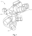
- FIGURE 1 illustrates an example of a microscope system 10 that may utilize orthogonal beam splitting.
- microscope system 10 includes an objective lens 20, one or more splitting systems 22 (22a-b), and one or more eyepieces 24.
- Microscope system 10 may be any suitable microscope, such as a surgical optical microscope.
- An optical microscope includes one or more lenses that produce an enlarged image of a target placed in the focal plane of the microscope. The lenses may focus light from (e.g., emitted or reflected from) the target towards a detector (such as an eye).
- the lenses may include objective lens 20, which gathers light from the target and focuses the light rays to produce a real image.
- An eyepiece 24 is located near the focal point of objective lens 20 to magnify the image.
- a splitting system 22 may split the light from the target and/or combine the target light with another light beam. Examples of splitting systems 22 are described in more detail in FIGURES 2 through 5 .
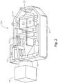
- FIGURE 2 illustrates an example of an orthogonal splitting system 22a that may be used with microscope system 10 of FIGURE 1 .
- splitting system 22a has a housing 30, within which are disposed a beamsplitter system 32, lenses 36 (36a-b), a mirror 40, and an image display 42.
- An image capture module 44 is coupled to housing 30.
- Beamsplitter system 32 comprises beamsplitter modules 34 (34a-c) and is described in more detail with reference to FIGURES 3 through 5 .
- Lenses 36 direct light beams to and/or from beamsplitter modules 34.
- Image display 42 may display one or more images and may be any suitable image display, such as a light-emitting diode (LED) (e.g., organic LED).
- Mirror 40 may reflect image beams with images towards lenses 36, which may direct the image beams towards beamsplitter modules 34.
- Beamsplitter modules 34 may combine the image beams with other light beams.
- Image capture module 44 may receive light beams and generate one or more images (such as a single image or a stream of images) from the light beams.
- image capture module 44 may be a video camera and may receive light beams from beamsplitter modules 34 through image forming objective lens 36b to generate video images.
- FIGURE 3 illustrates an example of a beamsplitter system 32 that may be utilized in a microscope system, such as microscope system 10.
- beamsplitter system 32 comprises beamsplitter modules 34 (34a-b).
- Beamsplitter module 34 may comprise any suitable beamsplitter that can receive a light beam 48 (48a-b) and split received beam 48 at a splitting region 49 (49a-b) to yield a plurality of split beams 50 (50a-b), 52 (50a-b).
- split beam 50 may be regarded as a transmitted beam
- split beam 52 may be regarded as a reflected beam.
- the transmitted and reflected beams may constitute any suitable proportions of received beam 48.
- the transmitted beam may be 50% and the reflected beam may be 50%, the transmitted beam may be less than 50% and the reflected beam may be greater than 50%, or the transmitted beam may be greater than 50% and the reflected beam may be less than 50%.
- a beamsplitter module 34 may operate within a suitable spectral range, e.g., the visible range.
- the transmitted beam travels along a transmitted beam optical path 56 (56a-b) (which may be substantially the same optical path 56 as used by the received beam), and the reflected beam travels along a reflected beam optical path 58 (58a-b) that may be any suitable angle to the transmitted beam optical path 56.
- the angle may be substantially 90°, less than 90°, or greater than 90°.
- the paths 56 and 58 may be regarded as defining an imaginary plane 60 (60a-b).
- a beamsplitter module 34 may be a cube beamsplitter comprising two cemented right angle prisms.
- the reflected and transmitted beams may travel through the same amount of glass, so although the optical path length of each arm is increased, both paths are increased by the same amount.
- beamsplitter module 34a is aligned with beamsplitter module 34b along an alignment line 64 in any suitable manner.
- the modules 34 may be aligned such that one or more of the following conditions are satisfied: (1) planes 60a-b are substantially parallel to each other; (2) alignment line 64 is orthogonal to one or more planes 60a-b; (3) alignment line 64 intersects one or more splitting regions 49a-b; and/or (4) transmitted optical paths 56a-b defines a plane that is orthogonal to a plane defined by reflected optical paths 58a-b.
- each beamsplitter module 34 may receive light beam 48 traveling along optical path 56. Beam 48 may have traveled from a target and through an objective lens to beamsplitter module 34. Beamsplitter module 34 may split the beam into split beams 50 and 52. Beamsplitter module 34 may transmit split beam 50 along a path that is substantially parallel to (e.g., substantially along) the first optical path. In certain arrangements , split beam 50 may be directed towards an eyepiece of a set of eyepieces. Beamsplitter module 34 may direct split beam 52 along a second optical path substantially orthogonal to the first optical path and to the alignment line. In certain arrangements, an image capture module may receive split beam 52 and generate one or more images from split beam 52.
- FIGURE 4 illustrates an example of a beamsplitter system 132 that may be utilized in a microscope system.
- beamsplitter system 132 comprises beamsplitter modules 134 (134a-b).
- Beamsplitter module 134 may comprise any suitable beamsplitter that can receive a light beam 148 (148a-b) and a light beam 152 (a-b) and combine beams 148 and 152 at a combining region 149 (149a-b) to yield a combined beam 150 (150a-b).
- beam 148 may be regarded as a primary beam
- beam 152 may be regarded as a secondary beam.
- the primary and secondary beams may constitute any suitable proportions of combined beam 150.
- the primary beam may be 50% and the secondary beam may be 50%, the primary beam may be less than 50% and the secondary beam may be greater than 50%, or the primary beam may be greater than 50% and the secondary beam may be less than 50%.
- a beamsplitter module 134 may operate within a suitable spectral range, e.g., the visible range or a narrow spectral band range.
- the primary beam travels along a primary beam optical path 156 (156a-b) (which may be substantially the same optical path 156 as used by the combined beam), and the secondary beam travels along a secondary beam optical path 158 (58a-b) that may be any suitable angle to the primary beam optical path 156.
- the angle may be substantially 90°, less than 90°, or greater than 90°.
- the paths 156 and 158 may be regarded as defining an imaginary plane 160 (60a-b).
- a beamsplitter module 134 may be a cube beamsplitter comprising two cemented right angle prisms.
- the primary and secondary beams may travel through the same amount of glass, so although the optical path length of each arm is increased, both paths are increased by the same amount.
- beamsplitter module 134a is aligned with beamsplitter module 134b along an alignment line 164 in any suitable manner.
- the modules 134 may be aligned such that one or more of the following conditions are satisfied: (1) planes 160a-b are substantially parallel to each other; (2) alignment line 164 is orthogonal to one or more planes 160a-b; (3) alignment line 164 intersects one or more combining regions 149a-b; and/or (4) primary optical paths 156a-b defines a plane that is orthogonal to a plane defined by secondary optical paths 158a-b.
- each beamsplitter module 134 may receive beam 148 traveling along optical path 156 and receive beam 152 traveling along optical path 158 that is substantially orthogonal to optical path 156 and to alignment line 164. Beamsplitter module 134 may transmit beam 148 and beam 152 along an output path that is substantially parallel to (e.g., along) optical path 156. In certain arrangements, beams 148 and 152 may be transmitted as combined beam 150 towards an eyepiece of a set of eyepieces. In certain arrangements, beam 148 may communicate an image of a target, and beam 152 may communicate one or more informational images conveying information such as microscope parameters. Beams 148 and 152 may be combined such as the images are injected into beam 148, e.g., the informational image is overlapped with the target image.
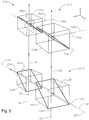
- FIGURE 5 illustrates an example of a beamsplitter system 232 that may be utilized in a microscope system.
- beamsplitter system 232 comprises an alpha beam splitter set 210 and a beta beam splitter set 212.
- a beam splitter set may be used for a beam splitting system 22 of FIGURE 1 .
- alpha beam splitter set 210 may comprise alpha beamsplitter modules, including beamsplitter modules 220 and 222. Modules 220 and 222 may be aligned along alignment line 224 in any suitable manner.
- modules 220 and 222 may be aligned such that one or more of the following conditions are satisfied: (1) a plane 226 defined by paths 56 and 58 and a plane 228 defined by paths 156 and 158 are substantially coplanar; and/or (2) alignment line 164 substantially coincides with path 58 and/or path 158.
- beamsplitter module 220 may be substantially similar to beamsplitter module 34. Beamsplitter module 220 may receive an alpha beam 48 traveling along an optical path 56 and split alpha beam 48 into an output beam 50 transmitted along optical path 56 and an alpha split beam 252 directed substantially parallel (e.g., along) to alignment line 224. In certain embodiments, beamsplitter module 222 may be substantially similar to beamsplitter module 134. Beamsplitter module 222 may receive a primary alpha beam 148 traveling along an optical path 156 and a secondary alpha beam 152 traveling along an optical path 158 that is substantially parallel (e.g., along) to alignment line 224. Beamsplitter module 222 may transmit beams 148 and 152 as an output beam 150 substantially parallel to optical path 156.
- beta beam splitter set 212 may be substantially similar to beamsplitter system 132 of FIGURE 4 .
- Beta beam splitter set 212 may comprise beta beamsplitter modules 134 aligned along alignment line 164. Each beta beamsplitter module 134 may receive output beam 50 or output beam 150. Beta beamsplitter module 134 may receive a secondary beta beam 152 traveling along a beta optical path 158 that is substantially orthogonal to a plane 260 defined by alignment line 164 and the optical path of the received output beam 50 or 150. Beta beamsplitter module 134 may transmit the received output beam 50 or 150 and secondary beta beam 152 along a path that is substantially parallel to the optical path of the received output beam 50 or 150.
- secondary beta beam 152 may be directed towards an eyepiece of a set of eyepieces. In certain embodiments, one or more images of secondary beta beam 152 may be injected into the received output beam 50 or 150.
- beta beam splitter set 212 may be substantially similar to beamsplitter system 32 of FIGURE 3 .
- Beta beam splitter set 212 may comprise beta beamsplitter modules 34 aligned along alignment line 64.
- Each beta beamsplitter module 34 may receive output beam 50 or output beam 150 and split the received output beam 50 or 150 into a beta split beams 50 and 52.
- Beta beamsplitter module 34 may transmit beta split beam 50 along a path that is substantially parallel to the optical path of the received output beam 50 or 150 and may direct beta split beam 52 along an optical path 58 substantially orthogonal to a plane defined by alignment line 64 and the optical path of the received output beam 50 or 150.
- beta split beam 50 may be directed towards an eyepiece of a set of eyepieces.
- an image capture module may receive beta split beam 52 and generate one or more images from beta split beam 52.
- a beamsplitter module may have any suitable spectral range, e.g., a broadband visible, IR, or UV range or a narrow spectral range, which may be less than 50 nm wide, e.g., a 520 to 540 nm range.
- spectral range e.g., a broadband visible, IR, or UV range
- narrow spectral range which may be less than 50 nm wide, e.g., a 520 to 540 nm range.
- broadband visible range beamsplitter modules may be used.
- narrow band beamsplitter modules may be used for image display 42. In this example, close to 100% of light from the target outside of narrow spectral range may be sent to the eye pieces 24.
Landscapes
- Physics & Mathematics (AREA)
- General Physics & Mathematics (AREA)
- Optics & Photonics (AREA)
- Chemical & Material Sciences (AREA)
- Analytical Chemistry (AREA)
- Engineering & Computer Science (AREA)
- Multimedia (AREA)
- Spectroscopy & Molecular Physics (AREA)
- Microscoopes, Condenser (AREA)
- Optical Elements Other Than Lenses (AREA)
Claims (5)
- Mikroskopsystem, das ein Strahlteilersystem (232) aufweist, wobei das Strahlteilersystem Folgendes umfasst:einen Alpha-Strahlteilersatz (210), der ein erstes Alpha-Strahlteilermodul (220) und ein zweites Alpha-Strahlteilermodul (222), das auf das erste Alpha-Strahlteilermodul entlang einer Alpha-Ausrichtungslinie (224) ausgerichtet ist, enthält,wobei das erste Alpha-Strahlteilermodul (220) konfiguriert ist, die folgenden Schritte auszuführen:Empfangen eines ersten Alphastrahls (48), der sich entlang eines ersten optischen Pfads (56) ausbreitet; undTeilen des ersten Alphastrahls (48) in einen ersten Ausgangsstrahl (50), der entlang des ersten optischen Pfads (56) übertragen wird, und in einen Alphateilstrahl (252), der im Wesentlichen parallel zu der Alpha-Ausrichtungslinie (224) orientiert ist; undwobei das zweite Alpha-Strahlteilermodul (222) konfiguriert ist, die folgenden Schritte auszuführen:Empfangen eines zweiten Alphastrahls (148), der ein Bild eines Ziels kommuniziert und sich entlang eines zweiten optischen Pfads (156) ausbreitet;Empfangen eines dritten Alphastrahls (152), der ein oder mehrere Informationsbilder kommuniziert, der sich entlang eines dritten optischen Alpha-Pfads (158) ausbreitet, der im Wesentlichen parallel zu der Alpha-Ausrichtungslinie (224) verläuft; undÜbertragen des zweiten Alphastrahls (148) und des dritten Alphastrahls (152) als einen zweiten Ausgangsstrahl (150) entlang des zweiten optischen Pfads (156); undeinen Beta-Strahlteilersatz (212), der ein erstes Beta-Strahlteilermodul (134a) und ein zweites Beta-Strahlteilermodul (134b), das auf das erste Beta-Strahlteilermodul entlang einer Beta-Ausrichtungslinie (164) ausgerichtet ist, umfasst, wobei jedes Beta-Strahlteilermodul konfiguriert ist, die folgenden Schritte auszuführen:Empfangen des ersten Ausgangsstrahls (50) oder des zweiten Ausgangsstrahls (150);Empfangen eines zweiten Betastrahls (152a, 152b), der sich entlang eines optischen Betapfads (158a, 158b) ausbreitet, der im Wesentlichen senkrecht zu einer Ebene (260) verläuft, die durch die Beta-Ausrichtungslinie (164) und den optischen Pfad des empfangenen Ausgangsstrahls (50, 150) definiert ist;wobei jedes Beta-Strahlteilermodul (134a, 134b) konfiguriert ist, den empfangenen Ausgangsstrahl (50) und den zweiten Betastrahl (152a) zu kombinieren, um ein oder mehrere Bilder des zweiten Betastrahls in den ersten empfangenen Ausgangsstrahl einzukoppeln,Kombinieren des empfangenen Ausgangsstrahls (50, 150) und des zweiten Betastrahls (152a, 152b), um einen kombinierten Strahl zu erhalten, so dass das eine oder mehrere Informationsbilder das Zielbild überlagern; undÜbertragen des kombinierten Strahls entlang des optischen Pfads des empfangenen Ausgangsstrahls in Richtung eines Okulars (24) eines Satzes von Okularen.
- System nach Anspruch 1, wobei jedes Beta-Strahlteilermodul (134a, 134b) konfiguriert ist, den kombinierten Strahl in Richtung eines Okulars (24) eines Satzes von Okularen zu richten.
- System nach Anspruch 1, wobei das zweite Beta-Strahlteilermodul (134b) konfiguriert ist, den zweiten Betastrahl (152b) von einer Bildanzeige zu empfangen.
- System nach Anspruch 1, wobei jedes Strahlteilermodul in einem schmalen Spektralbereich betrieben wird.
- System nach Anspruch 4, wobei das zweite Beta-Strahlteilermodul (134b) konfiguriert ist, Informationen wie etwa Mikroskop-Parameter zu empfangen.
Applications Claiming Priority (2)
| Application Number | Priority Date | Filing Date | Title |
|---|---|---|---|
| US13/490,692 US8937769B2 (en) | 2012-06-07 | 2012-06-07 | Orthogonal light beam splitting for microscopes |
| PCT/US2013/042212 WO2013184355A1 (en) | 2012-06-07 | 2013-05-22 | Orthogonal light beam splitting for microscopes |
Publications (3)
| Publication Number | Publication Date |
|---|---|
| EP2834701A1 EP2834701A1 (de) | 2015-02-11 |
| EP2834701A4 EP2834701A4 (de) | 2015-06-17 |
| EP2834701B1 true EP2834701B1 (de) | 2020-02-26 |
Family
ID=49712481
Family Applications (1)
| Application Number | Title | Priority Date | Filing Date |
|---|---|---|---|
| EP13800561.6A Active EP2834701B1 (de) | 2012-06-07 | 2013-05-22 | Orthogonale lichtstrahlaufspaltung für mikroskope |
Country Status (7)
| Country | Link |
|---|---|
| US (2) | US8937769B2 (de) |
| EP (1) | EP2834701B1 (de) |
| JP (3) | JP2015520419A (de) |
| CN (1) | CN104335099B (de) |
| AU (1) | AU2013272084B2 (de) |
| CA (1) | CA2872027A1 (de) |
| WO (1) | WO2013184355A1 (de) |
Families Citing this family (1)
| Publication number | Priority date | Publication date | Assignee | Title |
|---|---|---|---|---|
| US8937769B2 (en) * | 2012-06-07 | 2015-01-20 | Alcon Research, Ltd. | Orthogonal light beam splitting for microscopes |
Family Cites Families (20)
| Publication number | Priority date | Publication date | Assignee | Title |
|---|---|---|---|---|
| US4786155A (en) | 1986-12-16 | 1988-11-22 | Fantone Stephen D | Operating microscope providing an image of an obscured object |
| DE4243452A1 (de) * | 1992-12-22 | 1994-06-23 | Zeiss Carl Fa | Adapter zur dreidimensionalen Darstellung von stereoskopischen Abbildungen auf einer elektronischen Bildwiedergabevorrichtung |
| JPH06331895A (ja) * | 1993-05-24 | 1994-12-02 | Mitaka Koki Co Ltd | 顕微鏡の光学機構 |
| JPH1152287A (ja) * | 1997-07-15 | 1999-02-26 | Usa Government | 偏光均衡式ビームスプリッタ |
| CN1165792C (zh) * | 1999-10-13 | 2004-09-08 | 莱卡微系统(瑞士)股份公司 | 具有信息馈入装置的体视手术显微镜 |
| DE10103641A1 (de) | 2001-01-27 | 2002-08-01 | Leica Microsystems | Mikroskop |
| DE50201755D1 (de) * | 2001-02-23 | 2005-01-20 | Leica Microsystems Schweiz Ag | Optisches Instrument bzw. Gerät mit einem binokularen Einblick |
| EP1235094B1 (de) * | 2001-02-23 | 2006-04-19 | Leica Microsystems (Schweiz) AG | Erweiterte Blendensteuerung für Bildeinblendungen in einem Stereomikroskop |
| US6643070B2 (en) | 2001-02-23 | 2003-11-04 | Leica Microsystems (Schweiz) Ag | Viewing tube for an optical device |
| JP5259033B2 (ja) | 2001-08-03 | 2013-08-07 | オリンパス株式会社 | 内視鏡システム |
| US6909556B2 (en) * | 2002-01-14 | 2005-06-21 | Lightmaster Systems, Inc. | Design of prism assemblies and kernel configurations for use in projection systems |
| JP4062073B2 (ja) * | 2002-07-05 | 2008-03-19 | 日本ビクター株式会社 | 色分解及び色合成光学系 |
| DE10252837B4 (de) | 2002-11-13 | 2005-03-24 | Carl Zeiss | Untersuchungssystem und Untersuchungsverfahren |
| DE10304267B9 (de) | 2003-02-03 | 2005-12-15 | Carl Zeiss | Augenchirurgie-Mikroskopiesystem |
| DE102004026093B4 (de) * | 2004-05-25 | 2006-04-13 | Leica Microsystems Cms Gmbh | System und Verfahren zur Bildaufnahme und Bilddarstellung von Präparaten |
| DE102008001352B4 (de) * | 2008-04-23 | 2009-12-24 | Leica Microsystems (Schweiz) Ag | Stereomikroskop mit Strahlteilereinrichtung |
| TWI522085B (zh) | 2010-04-14 | 2016-02-21 | 愛爾康研究有限公司 | 用於眼外科控制台具有使用者可選式扇區的顯示器 |
| DE102010044502A1 (de) | 2010-09-06 | 2012-03-08 | Leica Microsystems (Schweiz) Ag | Sonderbeleuchtungs-Video-Operations-Stereomikroskop |
| IN2014DN08572A (de) * | 2012-05-01 | 2015-05-15 | Dsm Ip Assets Bv | |
| US8937769B2 (en) * | 2012-06-07 | 2015-01-20 | Alcon Research, Ltd. | Orthogonal light beam splitting for microscopes |
-
2012
- 2012-06-07 US US13/490,692 patent/US8937769B2/en active Active
-
2013
- 2013-05-22 AU AU2013272084A patent/AU2013272084B2/en not_active Ceased
- 2013-05-22 CN CN201380029078.XA patent/CN104335099B/zh not_active Expired - Fee Related
- 2013-05-22 WO PCT/US2013/042212 patent/WO2013184355A1/en not_active Ceased
- 2013-05-22 JP JP2015516039A patent/JP2015520419A/ja active Pending
- 2013-05-22 EP EP13800561.6A patent/EP2834701B1/de active Active
- 2013-05-22 CA CA2872027A patent/CA2872027A1/en not_active Abandoned
-
2014
- 2014-12-15 US US14/570,398 patent/US20150097940A1/en not_active Abandoned
-
2017
- 2017-08-15 JP JP2017156735A patent/JP6756678B2/ja active Active
-
2019
- 2019-06-17 JP JP2019111945A patent/JP2019194714A/ja active Pending
Non-Patent Citations (1)
| Title |
|---|
| None * |
Also Published As
| Publication number | Publication date |
|---|---|
| JP6756678B2 (ja) | 2020-09-16 |
| CA2872027A1 (en) | 2013-12-12 |
| US20150097940A1 (en) | 2015-04-09 |
| JP2019194714A (ja) | 2019-11-07 |
| CN104335099B (zh) | 2017-03-29 |
| CN104335099A (zh) | 2015-02-04 |
| EP2834701A4 (de) | 2015-06-17 |
| EP2834701A1 (de) | 2015-02-11 |
| JP2017223981A (ja) | 2017-12-21 |
| WO2013184355A1 (en) | 2013-12-12 |
| AU2013272084B2 (en) | 2016-09-22 |
| US8937769B2 (en) | 2015-01-20 |
| JP2015520419A (ja) | 2015-07-16 |
| AU2013272084A1 (en) | 2014-11-20 |
| US20130329298A1 (en) | 2013-12-12 |
Similar Documents
| Publication | Publication Date | Title |
|---|---|---|
| EP2115515B1 (de) | Optisches system mit gemeinsamer apertur mit einem lichtsensor und einer lichtquelle | |
| US9715097B2 (en) | Stereomicroscope having a main observer beam path and a co-observer beam path | |
| US9983396B2 (en) | Scanning microscope having focal position adjustment unit which includes a deflecting element | |
| US20150160448A1 (en) | Stereo microscope system | |
| US7439477B2 (en) | Laser condensing optical system | |
| US20170014030A1 (en) | Endoscope Featuring Depth Ascertainment | |
| US11002978B2 (en) | Microscope having a beam splitter assembly | |
| US8970959B2 (en) | Stereoscopic beam splitter | |
| US20140340669A1 (en) | Unknown | |
| EP2834701B1 (de) | Orthogonale lichtstrahlaufspaltung für mikroskope | |
| JP5389390B2 (ja) | 観察装置 | |
| JP4686135B2 (ja) | レーザ加工装置 | |
| US10088688B1 (en) | Compact common aperture imager system | |
| KR20150071420A (ko) | 복수 망원경을 갖춘 레이저 추적조준 광학계 | |
| CN115061270A (zh) | 一种倾斜模式望远显微组合成像方法 | |
| CN118356136A (zh) | 内窥镜可见光与近红外光合成成像镜头组件、系统及方法 |
Legal Events
| Date | Code | Title | Description |
|---|---|---|---|
| PUAI | Public reference made under article 153(3) epc to a published international application that has entered the european phase |
Free format text: ORIGINAL CODE: 0009012 |
|
| 17P | Request for examination filed |
Effective date: 20141104 |
|
| AK | Designated contracting states |
Kind code of ref document: A1 Designated state(s): AL AT BE BG CH CY CZ DE DK EE ES FI FR GB GR HR HU IE IS IT LI LT LU LV MC MK MT NL NO PL PT RO RS SE SI SK SM TR |
|
| AX | Request for extension of the european patent |
Extension state: BA ME |
|
| RA4 | Supplementary search report drawn up and despatched (corrected) |
Effective date: 20150520 |
|
| RIC1 | Information provided on ipc code assigned before grant |
Ipc: G02B 27/14 20060101ALN20150513BHEP Ipc: G02B 21/22 20060101ALI20150513BHEP Ipc: G02B 27/10 20060101AFI20150513BHEP |
|
| DAX | Request for extension of the european patent (deleted) | ||
| STAA | Information on the status of an ep patent application or granted ep patent |
Free format text: STATUS: EXAMINATION IS IN PROGRESS |
|
| 17Q | First examination report despatched |
Effective date: 20170331 |
|
| GRAP | Despatch of communication of intention to grant a patent |
Free format text: ORIGINAL CODE: EPIDOSNIGR1 |
|
| STAA | Information on the status of an ep patent application or granted ep patent |
Free format text: STATUS: GRANT OF PATENT IS INTENDED |
|
| GRAJ | Information related to disapproval of communication of intention to grant by the applicant or resumption of examination proceedings by the epo deleted |
Free format text: ORIGINAL CODE: EPIDOSDIGR1 |
|
| RIC1 | Information provided on ipc code assigned before grant |
Ipc: G02B 27/10 20060101AFI20190617BHEP Ipc: G02B 21/22 20060101ALI20190617BHEP Ipc: G02B 27/14 20060101ALN20190617BHEP |
|
| GRAP | Despatch of communication of intention to grant a patent |
Free format text: ORIGINAL CODE: EPIDOSNIGR1 |
|
| INTG | Intention to grant announced |
Effective date: 20190722 |
|
| RIN1 | Information on inventor provided before grant (corrected) |
Inventor name: BOUKHNY, MIKHAIL Inventor name: ARTSYUKHOVICH, ALEXANDER N. Inventor name: ASLAN, Z. ARAS |
|
| INTG | Intention to grant announced |
Effective date: 20190801 |
|
| GRAS | Grant fee paid |
Free format text: ORIGINAL CODE: EPIDOSNIGR3 |
|
| GRAA | (expected) grant |
Free format text: ORIGINAL CODE: 0009210 |
|
| STAA | Information on the status of an ep patent application or granted ep patent |
Free format text: STATUS: THE PATENT HAS BEEN GRANTED |
|
| RAP1 | Party data changed (applicant data changed or rights of an application transferred) |
Owner name: ALCON INC. |
|
| AK | Designated contracting states |
Kind code of ref document: B1 Designated state(s): AL AT BE BG CH CY CZ DE DK EE ES FI FR GB GR HR HU IE IS IT LI LT LU LV MC MK MT NL NO PL PT RO RS SE SI SK SM TR |
|
| REG | Reference to a national code |
Ref country code: GB Ref legal event code: FG4D |
|
| REG | Reference to a national code |
Ref country code: CH Ref legal event code: EP |
|
| REG | Reference to a national code |
Ref country code: AT Ref legal event code: REF Ref document number: 1238362 Country of ref document: AT Kind code of ref document: T Effective date: 20200315 |
|
| REG | Reference to a national code |
Ref country code: IE Ref legal event code: FG4D |
|
| REG | Reference to a national code |
Ref country code: DE Ref legal event code: R096 Ref document number: 602013066284 Country of ref document: DE |
|
| PG25 | Lapsed in a contracting state [announced via postgrant information from national office to epo] |
Ref country code: RS Free format text: LAPSE BECAUSE OF FAILURE TO SUBMIT A TRANSLATION OF THE DESCRIPTION OR TO PAY THE FEE WITHIN THE PRESCRIBED TIME-LIMIT Effective date: 20200226 Ref country code: NO Free format text: LAPSE BECAUSE OF FAILURE TO SUBMIT A TRANSLATION OF THE DESCRIPTION OR TO PAY THE FEE WITHIN THE PRESCRIBED TIME-LIMIT Effective date: 20200526 Ref country code: FI Free format text: LAPSE BECAUSE OF FAILURE TO SUBMIT A TRANSLATION OF THE DESCRIPTION OR TO PAY THE FEE WITHIN THE PRESCRIBED TIME-LIMIT Effective date: 20200226 |
|
| REG | Reference to a national code |
Ref country code: NL Ref legal event code: MP Effective date: 20200226 |
|
| REG | Reference to a national code |
Ref country code: LT Ref legal event code: MG4D |
|
| PG25 | Lapsed in a contracting state [announced via postgrant information from national office to epo] |
Ref country code: IS Free format text: LAPSE BECAUSE OF FAILURE TO SUBMIT A TRANSLATION OF THE DESCRIPTION OR TO PAY THE FEE WITHIN THE PRESCRIBED TIME-LIMIT Effective date: 20200626 Ref country code: BG Free format text: LAPSE BECAUSE OF FAILURE TO SUBMIT A TRANSLATION OF THE DESCRIPTION OR TO PAY THE FEE WITHIN THE PRESCRIBED TIME-LIMIT Effective date: 20200526 Ref country code: GR Free format text: LAPSE BECAUSE OF FAILURE TO SUBMIT A TRANSLATION OF THE DESCRIPTION OR TO PAY THE FEE WITHIN THE PRESCRIBED TIME-LIMIT Effective date: 20200527 Ref country code: LV Free format text: LAPSE BECAUSE OF FAILURE TO SUBMIT A TRANSLATION OF THE DESCRIPTION OR TO PAY THE FEE WITHIN THE PRESCRIBED TIME-LIMIT Effective date: 20200226 Ref country code: SE Free format text: LAPSE BECAUSE OF FAILURE TO SUBMIT A TRANSLATION OF THE DESCRIPTION OR TO PAY THE FEE WITHIN THE PRESCRIBED TIME-LIMIT Effective date: 20200226 Ref country code: HR Free format text: LAPSE BECAUSE OF FAILURE TO SUBMIT A TRANSLATION OF THE DESCRIPTION OR TO PAY THE FEE WITHIN THE PRESCRIBED TIME-LIMIT Effective date: 20200226 |
|
| PG25 | Lapsed in a contracting state [announced via postgrant information from national office to epo] |
Ref country code: NL Free format text: LAPSE BECAUSE OF FAILURE TO SUBMIT A TRANSLATION OF THE DESCRIPTION OR TO PAY THE FEE WITHIN THE PRESCRIBED TIME-LIMIT Effective date: 20200226 |
|
| PG25 | Lapsed in a contracting state [announced via postgrant information from national office to epo] |
Ref country code: DK Free format text: LAPSE BECAUSE OF FAILURE TO SUBMIT A TRANSLATION OF THE DESCRIPTION OR TO PAY THE FEE WITHIN THE PRESCRIBED TIME-LIMIT Effective date: 20200226 Ref country code: ES Free format text: LAPSE BECAUSE OF FAILURE TO SUBMIT A TRANSLATION OF THE DESCRIPTION OR TO PAY THE FEE WITHIN THE PRESCRIBED TIME-LIMIT Effective date: 20200226 Ref country code: PT Free format text: LAPSE BECAUSE OF FAILURE TO SUBMIT A TRANSLATION OF THE DESCRIPTION OR TO PAY THE FEE WITHIN THE PRESCRIBED TIME-LIMIT Effective date: 20200719 Ref country code: LT Free format text: LAPSE BECAUSE OF FAILURE TO SUBMIT A TRANSLATION OF THE DESCRIPTION OR TO PAY THE FEE WITHIN THE PRESCRIBED TIME-LIMIT Effective date: 20200226 Ref country code: EE Free format text: LAPSE BECAUSE OF FAILURE TO SUBMIT A TRANSLATION OF THE DESCRIPTION OR TO PAY THE FEE WITHIN THE PRESCRIBED TIME-LIMIT Effective date: 20200226 Ref country code: SM Free format text: LAPSE BECAUSE OF FAILURE TO SUBMIT A TRANSLATION OF THE DESCRIPTION OR TO PAY THE FEE WITHIN THE PRESCRIBED TIME-LIMIT Effective date: 20200226 Ref country code: CZ Free format text: LAPSE BECAUSE OF FAILURE TO SUBMIT A TRANSLATION OF THE DESCRIPTION OR TO PAY THE FEE WITHIN THE PRESCRIBED TIME-LIMIT Effective date: 20200226 Ref country code: SK Free format text: LAPSE BECAUSE OF FAILURE TO SUBMIT A TRANSLATION OF THE DESCRIPTION OR TO PAY THE FEE WITHIN THE PRESCRIBED TIME-LIMIT Effective date: 20200226 Ref country code: RO Free format text: LAPSE BECAUSE OF FAILURE TO SUBMIT A TRANSLATION OF THE DESCRIPTION OR TO PAY THE FEE WITHIN THE PRESCRIBED TIME-LIMIT Effective date: 20200226 |
|
| REG | Reference to a national code |
Ref country code: AT Ref legal event code: MK05 Ref document number: 1238362 Country of ref document: AT Kind code of ref document: T Effective date: 20200226 |
|
| REG | Reference to a national code |
Ref country code: DE Ref legal event code: R097 Ref document number: 602013066284 Country of ref document: DE |
|
| PLBE | No opposition filed within time limit |
Free format text: ORIGINAL CODE: 0009261 |
|
| STAA | Information on the status of an ep patent application or granted ep patent |
Free format text: STATUS: NO OPPOSITION FILED WITHIN TIME LIMIT |
|
| PG25 | Lapsed in a contracting state [announced via postgrant information from national office to epo] |
Ref country code: LI Free format text: LAPSE BECAUSE OF NON-PAYMENT OF DUE FEES Effective date: 20200531 Ref country code: IT Free format text: LAPSE BECAUSE OF FAILURE TO SUBMIT A TRANSLATION OF THE DESCRIPTION OR TO PAY THE FEE WITHIN THE PRESCRIBED TIME-LIMIT Effective date: 20200226 Ref country code: AT Free format text: LAPSE BECAUSE OF FAILURE TO SUBMIT A TRANSLATION OF THE DESCRIPTION OR TO PAY THE FEE WITHIN THE PRESCRIBED TIME-LIMIT Effective date: 20200226 Ref country code: CH Free format text: LAPSE BECAUSE OF NON-PAYMENT OF DUE FEES Effective date: 20200531 Ref country code: MC Free format text: LAPSE BECAUSE OF FAILURE TO SUBMIT A TRANSLATION OF THE DESCRIPTION OR TO PAY THE FEE WITHIN THE PRESCRIBED TIME-LIMIT Effective date: 20200226 |
|
| 26N | No opposition filed |
Effective date: 20201127 |
|
| PG25 | Lapsed in a contracting state [announced via postgrant information from national office to epo] |
Ref country code: PL Free format text: LAPSE BECAUSE OF FAILURE TO SUBMIT A TRANSLATION OF THE DESCRIPTION OR TO PAY THE FEE WITHIN THE PRESCRIBED TIME-LIMIT Effective date: 20200226 Ref country code: SI Free format text: LAPSE BECAUSE OF FAILURE TO SUBMIT A TRANSLATION OF THE DESCRIPTION OR TO PAY THE FEE WITHIN THE PRESCRIBED TIME-LIMIT Effective date: 20200226 |
|
| REG | Reference to a national code |
Ref country code: BE Ref legal event code: MM Effective date: 20200531 |
|
| PG25 | Lapsed in a contracting state [announced via postgrant information from national office to epo] |
Ref country code: LU Free format text: LAPSE BECAUSE OF NON-PAYMENT OF DUE FEES Effective date: 20200522 |
|
| PG25 | Lapsed in a contracting state [announced via postgrant information from national office to epo] |
Ref country code: IE Free format text: LAPSE BECAUSE OF NON-PAYMENT OF DUE FEES Effective date: 20200522 |
|
| PG25 | Lapsed in a contracting state [announced via postgrant information from national office to epo] |
Ref country code: BE Free format text: LAPSE BECAUSE OF NON-PAYMENT OF DUE FEES Effective date: 20200531 |
|
| PG25 | Lapsed in a contracting state [announced via postgrant information from national office to epo] |
Ref country code: TR Free format text: LAPSE BECAUSE OF FAILURE TO SUBMIT A TRANSLATION OF THE DESCRIPTION OR TO PAY THE FEE WITHIN THE PRESCRIBED TIME-LIMIT Effective date: 20200226 Ref country code: MT Free format text: LAPSE BECAUSE OF FAILURE TO SUBMIT A TRANSLATION OF THE DESCRIPTION OR TO PAY THE FEE WITHIN THE PRESCRIBED TIME-LIMIT Effective date: 20200226 Ref country code: CY Free format text: LAPSE BECAUSE OF FAILURE TO SUBMIT A TRANSLATION OF THE DESCRIPTION OR TO PAY THE FEE WITHIN THE PRESCRIBED TIME-LIMIT Effective date: 20200226 |
|
| PG25 | Lapsed in a contracting state [announced via postgrant information from national office to epo] |
Ref country code: MK Free format text: LAPSE BECAUSE OF FAILURE TO SUBMIT A TRANSLATION OF THE DESCRIPTION OR TO PAY THE FEE WITHIN THE PRESCRIBED TIME-LIMIT Effective date: 20200226 Ref country code: AL Free format text: LAPSE BECAUSE OF FAILURE TO SUBMIT A TRANSLATION OF THE DESCRIPTION OR TO PAY THE FEE WITHIN THE PRESCRIBED TIME-LIMIT Effective date: 20200226 |
|
| P01 | Opt-out of the competence of the unified patent court (upc) registered |
Effective date: 20230504 |
|
| PGFP | Annual fee paid to national office [announced via postgrant information from national office to epo] |
Ref country code: DE Payment date: 20250423 Year of fee payment: 13 |
|
| PGFP | Annual fee paid to national office [announced via postgrant information from national office to epo] |
Ref country code: FR Payment date: 20250422 Year of fee payment: 13 |
|
| PGFP | Annual fee paid to national office [announced via postgrant information from national office to epo] |
Ref country code: GB Payment date: 20260313 Year of fee payment: 14 |