EP2834532B1 - Belagträgerplatte für einen bremsbelag - Google Patents
Belagträgerplatte für einen bremsbelag Download PDFInfo
- Publication number
- EP2834532B1 EP2834532B1 EP13735016.1A EP13735016A EP2834532B1 EP 2834532 B1 EP2834532 B1 EP 2834532B1 EP 13735016 A EP13735016 A EP 13735016A EP 2834532 B1 EP2834532 B1 EP 2834532B1
- Authority
- EP
- European Patent Office
- Prior art keywords
- carrier plate
- lining
- lining carrier
- brake
- thermal expansion
- Prior art date
- Legal status (The legal status is an assumption and is not a legal conclusion. Google has not performed a legal analysis and makes no representation as to the accuracy of the status listed.)
- Not-in-force
Links
- 229910052751 metal Inorganic materials 0.000 claims description 14
- 239000002184 metal Substances 0.000 claims description 14
- 239000010410 layer Substances 0.000 description 7
- 229910000831 Steel Inorganic materials 0.000 description 6
- 238000009826 distribution Methods 0.000 description 6
- 239000010959 steel Substances 0.000 description 6
- 239000002131 composite material Substances 0.000 description 4
- 238000001816 cooling Methods 0.000 description 4
- RTAQQCXQSZGOHL-UHFFFAOYSA-N Titanium Chemical compound [Ti] RTAQQCXQSZGOHL-UHFFFAOYSA-N 0.000 description 3
- 150000002739 metals Chemical class 0.000 description 3
- 229910052719 titanium Inorganic materials 0.000 description 3
- 239000010936 titanium Substances 0.000 description 3
- 238000004026 adhesive bonding Methods 0.000 description 2
- 238000010438 heat treatment Methods 0.000 description 2
- 239000011810 insulating material Substances 0.000 description 2
- 238000003466 welding Methods 0.000 description 2
- 229910000838 Al alloy Inorganic materials 0.000 description 1
- 229910000851 Alloy steel Inorganic materials 0.000 description 1
- 229910001369 Brass Inorganic materials 0.000 description 1
- 239000012790 adhesive layer Substances 0.000 description 1
- 229910052782 aluminium Inorganic materials 0.000 description 1
- XAGFODPZIPBFFR-UHFFFAOYSA-N aluminium Chemical compound [Al] XAGFODPZIPBFFR-UHFFFAOYSA-N 0.000 description 1
- 238000005452 bending Methods 0.000 description 1
- 230000005540 biological transmission Effects 0.000 description 1
- 239000010951 brass Substances 0.000 description 1
- 230000006835 compression Effects 0.000 description 1
- 238000007906 compression Methods 0.000 description 1
- 238000010276 construction Methods 0.000 description 1
- 238000002788 crimping Methods 0.000 description 1
- 230000001419 dependent effect Effects 0.000 description 1
- 238000010586 diagram Methods 0.000 description 1
- 230000000694 effects Effects 0.000 description 1
- 239000000835 fiber Substances 0.000 description 1
- 239000002657 fibrous material Substances 0.000 description 1
- 239000012530 fluid Substances 0.000 description 1
- 239000002783 friction material Substances 0.000 description 1
- 230000017525 heat dissipation Effects 0.000 description 1
- 238000004519 manufacturing process Methods 0.000 description 1
- 239000000463 material Substances 0.000 description 1
- 238000003825 pressing Methods 0.000 description 1
- 239000010935 stainless steel Substances 0.000 description 1
- 229910001220 stainless steel Inorganic materials 0.000 description 1
Images


Classifications
-
- F—MECHANICAL ENGINEERING; LIGHTING; HEATING; WEAPONS; BLASTING
- F16—ENGINEERING ELEMENTS AND UNITS; GENERAL MEASURES FOR PRODUCING AND MAINTAINING EFFECTIVE FUNCTIONING OF MACHINES OR INSTALLATIONS; THERMAL INSULATION IN GENERAL
- F16D—COUPLINGS FOR TRANSMITTING ROTATION; CLUTCHES; BRAKES
- F16D65/00—Parts or details
- F16D65/78—Features relating to cooling
-
- F—MECHANICAL ENGINEERING; LIGHTING; HEATING; WEAPONS; BLASTING
- F16—ENGINEERING ELEMENTS AND UNITS; GENERAL MEASURES FOR PRODUCING AND MAINTAINING EFFECTIVE FUNCTIONING OF MACHINES OR INSTALLATIONS; THERMAL INSULATION IN GENERAL
- F16D—COUPLINGS FOR TRANSMITTING ROTATION; CLUTCHES; BRAKES
- F16D65/00—Parts or details
- F16D65/02—Braking members; Mounting thereof
- F16D65/04—Bands, shoes or pads; Pivots or supporting members therefor
- F16D65/092—Bands, shoes or pads; Pivots or supporting members therefor for axially-engaging brakes, e.g. disc brakes
-
- F—MECHANICAL ENGINEERING; LIGHTING; HEATING; WEAPONS; BLASTING
- F16—ENGINEERING ELEMENTS AND UNITS; GENERAL MEASURES FOR PRODUCING AND MAINTAINING EFFECTIVE FUNCTIONING OF MACHINES OR INSTALLATIONS; THERMAL INSULATION IN GENERAL
- F16D—COUPLINGS FOR TRANSMITTING ROTATION; CLUTCHES; BRAKES
- F16D69/00—Friction linings; Attachment thereof; Selection of coacting friction substances or surfaces
- F16D69/04—Attachment of linings
- F16D2069/0425—Attachment methods or devices
- F16D2069/0483—Lining or lining carrier material shaped in situ
Definitions
- the invention relates to a lining carrier plate of a brake shoe, which is designed to hold a friction lining.
- Pad carrier plates for brake shoes of the type mentioned are known in the art.
- the construction of lining carrier plates, in particular those for brake shoes of writing brakes, is often similar in its basic structure.
- a friction lining is applied, for example by means of an adhesive layer.
- the friction lining comes into braking contact with a brake disk or a brake drum during braking, converting kinetic energy into thermal energy. Due to the increase in temperature, brake disc and brake shoes expand and under certain circumstances also deform, which, in addition to changes in the frictional properties of the friction partners due to the temperature increase due to the changed pressure distribution, has an additional influence on the braking behavior.
- a brake shoe for a disc brake which comprises a carrier having on a side facing the piston of a brake cylinder side a heat-insulating, porous pressure transmitting body made of resin-bonded fibers for the piston.
- the pressure transmitting body is inserted into a recess of the carrier for the brake pad.
- the pressure transmitting body is made of molded fiber material. This should be the Heat transfer to the brake fluid can be reduced.
- the DE 20 2009 012 778 U1 discloses a composite brake pad sole and a composite brake pad, wherein the composite brake pad sole has a plate-shaped base body having a support surface on an inner side for a plastic mass of the composite brake pad, wherein the base body comprises at least one steel insert.
- the steel insert extends substantially over the entire length of the main body and has a non-rectangular cross section, preferably a circular cross section.
- the DE 10 2008 024 194 A1 discloses a brake pad assembly for bicycle disc brakes having a friction brake pad and a back plate.
- the back plate includes a first layer deposited on the friction brake pad and a second layer deposited on the first layer.
- the first layer consists of an aluminum alloy and the second layer of stainless steel.
- the back plate has a thickness of about 1.7 to 1.8 mm.
- the cooling plate has sections with cooling fins for heat dissipation.
- a brake pad with a pad surface is mechanically attached to a mounting area of the cooling plate.
- the brake lining consists of a friction lining which is rigidly and firmly connected to a monolithic element on a lining carrier plate.
- the mounting area consists of a good heat-conducting metal, preferably made of brass, aluminum or alloy steel.
- the brake pad has rivet sections for attachment to the cold plate and to a mounting plate.
- a friction lining for disc brakes for road and rail vehicles which has a support plate made of steel with a thin-walled Rauhground phenomenon of a metal sheet and an intermediate layer with functional block mounted thereon of a friction material.
- the friction lining carrier is provided with at least one window-like opening.
- a filling or insulating material can be used, preferably a plastic.
- metallic filling or insulating materials are provided.
- portions of the rough ground carrier are pressed into the window-like openings. There may be an additional welding of the Rauhground varietiess with the Reibbelagieri.
- a pneumatically and / or electric motor operated disc brake known with a brake disc cross-caliper, at least one arranged in the caliper adjusting device to compensate for Bremsbelag- and Bremsscalenverschl founded by adjusting the distance between at least one brake pad and the brake disc, the two axially movable adjusting elements with each comprises a pressure piece.
- the two adjusting elements of the adjusting device are secured against rotation in their facing the respective brake pad area on a common connection plate.
- On the connecting plate and / or on the pressure piece on the side facing the respective brake lining a single or multi-part heat-insulating layer is at least partially attached.
- Object of the present invention is to develop a lining carrier plate of the type mentioned in such a way that it has an optimized hot braking behavior.
- a lining carrier plate according to the invention of a brake shoe which is designed to hold a friction lining, has a first part made of a first metal having a first thermal expansion behavior and at least one second part mechanically connected to the first part made of a second metal having a second thermal expansion behavior, wherein the first Thermal expansion behavior and the second thermal expansion behavior of the respective metals are different.
- Suitable first and second materials are steel and titanium.
- the thermal expansion of steel is in the range of 11 to 25 * 10-6 K-1 and that of titanium at 9 * 10-6 K-1.
- the friction lining can be attached to the lining carrier plate by conventional fastening measures, for example by gluing or vulcanizing.
- the pad carrier plate may have any outer contours, as required by different brake systems. An embodiment is possible as a hammer head plate or known so-called push geometry.
- the first part is embedded in the second part.
- the contact surface to the friction lining consists of a metal, whereby local force peaks on the friction lining by the different thermal expansion behavior, for example by shear forces can be prevented.
- the first part and the second part are connected to one another in a material-locking manner. This can be achieved for example by welding or gluing. Such a cohesive connection of the two parts allows a large-area power transmission during deformation.
- the first part and the at least one second part are fixed to each other.
- Such setting can be done by pressing, crimping, riveting, screwing or other known fixing means. With the help of such a definition, the manufacturing cost can be reduced.
- the metal of the first part has a greater coefficient of thermal expansion than the metal of the second part.
- the first part and the second part are arranged one behind the other viewed in the pressure direction.
- a deformation of the outer regions of the lining carrier plates is achieved transversely to the printing direction, in the printing direction or from the printing direction, so that depending on the required application, a bending of the lining carrier plate can be achieved such that the friction lining at the edges more or less strongly on the Friction partner, such as a disc brake rubs.
- the first part is designed as a mechanically connected insert in the second part. In this way, a targeted deformation of the lining carrier plate can be achieved depending on the geometry of the insert.
- the first part is arranged on the inside along the direction of compression, so that the first part is arranged on a side facing away from the friction lining.
- a first independent object of the invention relates to a brake shoe with a friction lining and a lining carrier plate according to the inventive idea described above.
- Figures 1A and 1B show a top view ( Figure 1 A) and a perspective view ( FIG. 1 B) to a lining carrier plate 2 according to the invention.
- the lining carrier plate 2 has two parts 4, 6 of two different metals, part 6 made of titanium and part 4 of steel, which are mechanically interconnected.
- the first part 4 is inserted into the second part 6 and welded in the illustrated embodiment.
- the first part 4 has a greater coefficient of thermal expansion than the second part 6.
- the first part 4 is presently triangular, in particular isosceles triangular.
- Other geometries are also conceivable within the scope of the invention, for example rectangular or strip-like configurations.
- the first part 4 is designed to project in the printing direction D, but it can also be designed as an insert, which is arranged only on one side of the lining carrier plate 2 according to the invention.
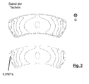
- FIG. 2 shows a conventional friction lining according to the prior art, its thermal expansion behavior (top illustration) and the resulting pressure distribution (bottom diagram).
- the thermal expansion of the conventional brake shoe is greatest in the edge regions transverse to the printing direction D and thus leads to pressure distributions in the illustrated embodiment, a maximum pressure of 9.2 megapascals in the edge regions.
- a lining carrier according to the invention as in FIG. 3 is shown by the use of an at least two-part lining carrier plate given a stronger deformation in the edge regions, so that here with otherwise the same boundary conditions as in the embodiment in FIG. 2 Maximum pressure of 9.5 megapascals.
Landscapes
- Engineering & Computer Science (AREA)
- General Engineering & Computer Science (AREA)
- Mechanical Engineering (AREA)
- Braking Arrangements (AREA)
Description
- Die Erfindung betrifft eine Belagträgerplatte einer Bremsbacke, welche zur Halterung eines Reibbelages ausgebildet ist.
- Belagträgerplatten für Bremsbacken der eingangs genannten Art sind im Stand der Technik bekannt. Der Aufbau von Belagträgerplatten, insbesondere von solchen für Bremsbacken von Schreibenbremsen, ist in seiner Grundstruktur häufig ähnlich. Auf einer entsprechenden Belagträgerplatte wird ein Reibbelag aufgebracht, beispielsweise mittels einer Klebeschicht.
- Der Reibbelag tritt beim Bremsen in reibenden Kontakt mit einer Bremsscheibe oder einer Bremstrommel und setzt dabei kinetische Energie in Wärmeenergie um. Durch die Temperaturerhöhung dehnen sich Bremsscheibe und Bremsbacken aus und verformen sich unter Umständen auch, was neben Veränderungen der Reibeigenschaften der Reibpartner durch die Temperaturerhöhung durch die veränderten Druckverteilung einen zusätzlichen Einfluss auf das Bremsverhalten hat.
- So wurde bei herkömmlichen Scheibenbremsen festgestellt, dass sich unerwünschtermaßen kleine Bereiche hoher Temperatur bilden können, sog. hot spots, über die ein zu hoher Anteil des Bremsdruckes auf vergleichsweise kleiner Fläche aufgebracht wird. Mögliche Folgen sind erhöhter Verschleiß, Bremsenquietschen und geringere Gesamtbremsleistung.
- Aus der
DE 10 2005 048 109 A1 ist eine Bremsbacke für eine Scheibenbremse bekannt, die einen Träger aufweist, der auf einer dem Kolben eines Bremszylinders zugekehrten Seite einen wärmedämmenden, porösen Druckübertragungskörper aus mit Kunstharz gebundenen Fasern für den Kolben aufweist. Der Druckübertragungskörper ist in eine Ausnehmung des Trägers für den Bremsbelag eingesetzt. Der Druckübertragungskörper ist aus gegossenem Fasermaterial hergestellt. Damit soll die Wärmeübertragung auf die Bremsflüssigkeit reduziert werden. - Die
DE 20 2009 012 778 U1 offenbart eine Verbundbremsklotzsohle und einen Verbundbremsklotz, wobei die Verbundbremsklotzsohle einen plattenförmigen Grundkörper mit einer Tragfläche auf einer Innenseite für eine Kunststoffmasse des Verbundbremsklotzes aufweist, wobei der Grundkörper wenigstens eine Stahleinlage aufweist. Die Stahleinlage ist im Wesentlichen über die gesamte Länge des Grundkörpers erstreckt und weist einen nicht rechteckförmigen Querschnitt, vorzugsweise einen kreisförmigen Querschnitt auf. - Die
DE 10 2008 024 194 A1 offenbart eine Bremsbelagbaugruppe für Fahrradscheibenbremsen mit einem Reibungsbremsbelag und einer Rückenplatte. Die Rückenplatte beinhaltet eine erste Schicht, die auf dem Reibungsbremsbelag abgelagert ist, und eine zweite Schicht, die auf der ersten Schicht abgelagert ist. Die erste Schicht besteht aus einer Aluminiumlegierung und die zweite Schicht aus rostfreiem Edelstahl. Die Rückenplatte weist eine Dicke von ca. 1,7 bis 1,8 mm auf. - Aus der
US 2012/0000735 A1 ist eine Bremsbacke mit Kühlflächen für eine Fahrradbremse bekannt. Die Kühlplatte weist Abschnitte mit Kühlrippen zur Wärmeableitung auf. Ein Bremsbelag mit einer Bremsbelagoberfläche ist mechanisch an einem Befestigungsbereich der Kühlplatte befestigt. Der Bremsbelag besteht aus einem Reibbelag, der auf einer Belagträgerplatte starr und fest zu einem monolithischen Element verbunden ist. Der Befestigungsbereich besteht aus einem gut wärmeleitenden Metall, bevorzugt aus Messing, Aluminium oder legiertem Stahl. Der Bremsbeleg weist Nietabschnitte zur Befestigung an die Kühlplatte und an eine Befestigungsplatte auf. - Aus der
US 2004/0099493 A1 ist ein Reibbelag für Scheibenbremsen für Straßen- und Schienenfahrzeuge bekannt, welcher eine Trägerplatte aus Stahl mit einem dünnwandigen Rauhgrundträger aus einem Metallblech und eine Zwischenschicht mit darauf befestigten Funktionsblock aus einem Reibmaterial aufweist. Der Reibbelagträger ist mit mindestens einer fensterartigen Durchbrechung versehen. In diese Durchbrechung kann ein Füll- oder Dämmmaterial eingesetzt werden, bevorzugt ein Kunststoff. Zur Erhöhung bzw. Verbesserung des Wärmeflusses sind metallische Füll- bzw. Dämmmaterialien vorgesehen. Ebenfalls ist vorgesehen, dass Abschnitte des Rauhgrundträgers in die fensterartigen Durchbrechungen eingedrückt werden. Es kann ein zusätzliches Verschweißen des Rauhgrundträgers mit dem Reibbelagträger erfolgen. - Aus der
US 2006/0124405 A1 ist eine pneumatisch und/oder elektromotorisch betätigbare Scheibenbremse bekannt mit einem eine Bremsscheibe übergreifenden Bremssattel, mindestens einer im Bremssattel angeordneten Nachstelleinrichtung zum Ausgleich von Bremsbelag- und/oder Bremsscheibenverschleiß durch Verstellen des Abstandes zwischen wenigstens einem Bremsbelag und der Bremsscheibe, die zwei axial bewegbare Nachstellelemente mit jeweils einem Druckstück umfasst. Die beiden Nachstellelemente der Nachstelleinrichtung sind verdrehsicher in ihrem zum jeweiligen Bremsbelag weisenden Bereich an einer gemeinsamen Verbindungsplatte befestigt. An der Verbindungsplatte und/oder am Druckstück auf der dem jeweiligen Bremsbelag zugewandten Seite ist zumindest bereichsweise eine ein- oder mehrteilige wärmeisolierende Schicht angebracht. - Aufgabe der vorliegenden Erfindung ist es, eine Belagträgerplatte der eingangs genannten Art dahingehend weiterzubilden, dass sie ein optimiertes Heißbremsverhalten aufweist.
- Die Aufgabe wird gelöst durch eine Belagträgerplatte gemäß Anspruch 1. Weitere Ausgestaltungen der Erfindung sind Gegenstand der Unteransprüche.
- Eine erfindungsgemäße Belagträgerplatte einer Bremsbacke, welche zur Halterung eines Reibbelages ausgebildet ist, weist einen ersten Teil aus einem ersten Metall mit einem ersten Wärmeausdehnungsverhalten und wenigstens einen mit dem ersten Teil mechanisch verbundenen zweiten Teil aus einem zweiten Metall mit einem zweiten Wärmeausdehnungsverhalten auf, wobei das erste Wärmeausdehnungsverhalten und das zweite Wärmeausdehnungsverhalten der jeweiligen Metalle unterschiedlich sind.
- Geeignete erste und zweite Materialien sind Stahl und Titanium. So liegt die Wärmedehnung von Stahl im Bereich von 11 bis 25 *10-6 K-1 und die von Titanium bei 9 * 10-6 K-1.
- Der Reibbelag kann auf der Belagträgerplatte durch übliche Befestigungsmaßnahmen befestigt werden, beispielsweise durch Kleben oder vulkanisieren. Die Belagträgerplatte kann beliebige Außenkonturen aufweisen, wie sie von unterschiedlichen Bremsensystemen erforderlich sind. Möglich ist eine Ausgestaltung als Hammerkopfplatte oder bekannte sogenannte Push-Geometrie.
- Durch die mechanische Verbindung des ersten Teils und des zweiten Teils und durch die unterschiedlichen Wärmeausdehnungsverhalten des ersten Teils und des zweiten Teils kann bei Erwärmung der erfindungsgemäßen Belagträgerplatte eine gezielte Verformung der Belagträgerplatte und damit einer entsprechend ausgestatteten Bremsbacke erreicht werden, so dass sich die Druckverteilung des Bremsdruckes einer entsprechend ausgestatteten Scheibenbremse im Heißbremsfalle gezielt beeinflussen lässt. Unerwünschte undefinierte Temperatur- und Belastungsspitzen können mit Hilfe einer erfindungsgemäßen Belagträgerplatte vermieden werden.
- Statt zweier Teile unterschiedlicher Wärmeausdehnungsverhalten können auch mehrere Teile vorgesehen sein, die jeweils mechanisch miteinander verbunden sind. Diese mehreren Teile können aus zwei oder mehreren unterschiedlichen Metallen bestehen, um das Wärmeausdehnungsverhalten der Belagträgerplatte gezielt zu beeinflussen.
- Erfindungsgemäß ist vorgesehen, dass der erste Teil in den zweiten Teil eingelassen ist. Auf diese Weise kann beispielsweise erreicht werden, dass die Kontaktfläche zum Reibbelag aus einem Metall besteht, wodurch lokale Kraftspitzen auf den Reibbelag durch die unterschiedlichen Wärmeausdehnungsverhalten, beispielsweise durch Scherkräfte, verhindert werden können.
- Gemäß einer ersten möglichen Ausgestaltung der Erfindung kann vorgesehen sein, dass der erste Teil und der zweite Teil stoffschlüssig miteinander verbunden sind. Dies kann beispielsweise durch Schweißen oder Kleben erreicht werden. Eine derartige stoffschlüssige Verbindung der beiden Teile ermöglicht eine großflächige Kraftübertragung während der Verformung.
- Gemäß einer alternativen Ausgestaltung der erfindungsgemäßen Belagträgerplatte kann vorgesehen sein, dass der erste Teil und der wenigstens eine zweite Teil aneinander festgelegt sind. Ein solches Festlegen kann durch Pressen, Crimpen, Nieten, Schrauben oder durch andere bekannte Festlegungsmittel geschehen. Mit Hilfe einer derartigen Festlegung lässt sich der Fertigungsaufwand reduzieren.
- Gemäß einer weiteren möglichen Ausgestaltung der Erfindung kann vorgesehen sein, dass das Metall des ersten Teils einen größeren Wärmeausdehnungskoeffizienten als das Metall des zweiten Teils aufweist. Bei Erwärmung der Belagträgerplatte wird somit erreicht, dass sich der erste Teil stärker ausdehnt als der zweite Teil, wodurch in Verbindung mit später beschriebenen geeigneten Geometrien geeignete Verformungen zur Bewerkstelligung gewünschter Effekte erzielt werden können.
- Gemäß einer weiteren möglichen Ausgestaltung der Erfindung kann vorgesehen sein, dass der erste Teil und der zweite Teil in Druckrichtung betrachtet hintereinander angeordnet sind. Auf diese Weise wird eine Verformung der Außenbereiche der Belagträgerplatten quer zur Druckrichtung, in Druckrichtung oder von der Druckrichtung weg erreicht, so dass sich je nach benötigtem Anwendungsfall eine Biegung der Belagträgerplatte derart erreichen lässt, dass der Reibbelag an den Kanten stärker oder weniger stark an dem Reibpartner, beispielsweise einer Scheibenbremse, reibt. Gemäß einer weiteren möglichen Ausgestaltung der Erfindung kann vorgesehen sein, dass der erste Teil als mechanisch verbundener Einsatz in den zweiten Teil ausgebildet ist. Auf diese Weise kann eine gezielte Verformung der Belagträgerplatte abhängig von der Geometrie des Einsatzes erreicht werden.
- Gemäß einer weiteren möglichen Ausgestaltung der Erfindung kann vorgesehen sein, dass der erste Teil längs zur Druckrichtung innenliegend angeordnet ist, sodass der erste Teil auf einer dem Reibbelag abgewandten Seite angeordnet ist.
- Ein erster unabhängiger Gegenstand der Erfindung betrifft eine Bremsbacke mit einem Reibbelag und einer Belagträgerplatte gemäß dem zuvor beschriebenen Erfindungsgedanken.
- Weitere Ziele, Merkmale sowie vorteilhafte Anwendungsmöglichkeiten der Erfindung ergeben sich aus der nachfolgenden Beschreibung eines Ausführungsbeispiels anhand der Zeichnungen. Dabei bilden sämtliche beschriebenen und/oder bildlich dargestellten Merkmale in ihrer sinnvollen Kombination den Gegenstand der vorliegenden Erfindung, auch unabhängig von den Patentansprüchen und deren Rückbezügen.
- Die Erfindung wird anhand eines Ausführungsbeispiels erläutert. Dabei zeigen schematisch:
- Fig. 1A, B
- eine Draufsicht und eine perspektivische Ansicht auf eine erfindungsgemäße Belagträgerplatte;
- Fig. 2
- eine Ansicht der Hochtemperaturdruckverteilung eines herkömmlichen Reibbelages sowie
- Fig. 3
- eine Ansicht einer Hochtemperaturdruckverteilung eines Reibbelages einer erfindungsgemäßen Bremsbacke.
-
Figuren 1A und 1B zeigen eine Draufsicht (Figur 1 A) und eine perspektivische Ansicht (Figur 1 B) auf eine erfindungsgemäße Belagträgerplatte 2. - Die Belagträgerplatte 2 weist zwei Teile 4, 6 aus zwei unterschiedlichen Metallen, Teil 6 aus Titanium und Teil 4 aus Stahl auf, welche mechanisch miteinander verbunden sind. Der erste Teil 4 ist in den zweiten Teil 6 eingesetzt und im dargestellten Ausführungsbeispiel verschweißt.
- Das erste Teil 4 weist einen größeren Wärmeausdehnungskoeffizienten auf als das zweite Teil 6. Das erste Teil 4 ist vorliegend dreieckig, insbesondere gleichschenklig dreieckig ausgebildet. Andere Geometrien sind im Rahmen der Erfindung ebenfalls denkbar, beispielsweise rechteckige bzw. streifenartige Ausgestaltungen.
- In dem dargestellten Ausführungsbeispiel ist das erste Teil 4 in Druckrichtung D durchragend ausgestaltet, es kann jedoch auch als Einsatzteil ausgebildet sein, welches nur auf einer Seite der erfindungsgemäßen Belagträgerplatte 2 angeordnet ist.
-
Figur 2 zeigt einen herkömmlichen Reibbelag nach dem Stand der Technik, sein Wärmeausdehnungsverhalten (obere Darstellung) sowie die daraus resultierende Druckverteilung (untere Darstellung). - Die Wärmeausdehnung der herkömmlichen Bremsbacke ist in den Randbereichen quer zur Druckrichtung D am größten und führt somit zu Druckverteilungen mit im dargestellten Ausführungsbeispiel Druck maximal in Höhe von 9,2 Megapascal in den Randbereichen.
- Bei einem erfindungsgemäßen Belagträger, wie er in
Figur 3 dargestellt ist, ist durch die Verwendung einer wenigstens zweiteiligen Belagträgerplatte eine stärkere Verformung in den Randbereichen gegeben, so dass sich hier bei ansonsten gleichen Randbedingungen wie bei dem Ausführungsbeispiel inFigur 2 Druck maximal von 9,5 Megapascal erreichen lassen. -
- 2
- Belagträgerplatte
- 4
- erstes Teil
- 6
- zweites Teil
- D
- Druckrichtung
Claims (7)
- Belagträgerplatte (2) einer Bremsbacke, welche zur Halterung eines Reibbelages ausgebildet ist, wobei die Belagträgerplatte (2) einen ersten Teil (4) aus einem ersten Metall mit einem ersten Wärmeausdehnungsverhalten und wenigstens einen mit dem ersten Teil (4) mechanisch verbundenen zweiten Teil (6) aus einem zweiten Metall mit einem zweiten Wärmeausdehnungsverhalten aufweist, wobei das erste Wärmeausdehnungsverhalten und das zweite Wärmeausdehnungsverhalten unterschiedlich sind, wobei der erste Teil (4) als mechanisch verbundener Einsatz in den zweiten Teil (6) ausgebildet ist und dass der erste Teil (4) den zweiten Teil (6) durchragt, dadurch gekennzeichnet, dass der erste Teil (4) in den zweiten Teil (6) eingelassen ist.
- Belagträgerplatte nach Anspruch 1, dadurch gekennzeichnet, dass der erste Teil (4) und der zweite Teil (6) stoffschlüssig miteinander verbunden sind.
- Belagträgerplatte nach Anspruch 1, dadurch gekennzeichnet, dass der erste Teil (4) und der zweite Teil (6) aneinander festgelegt sind.
- Belagträgerplatte nach einem der vorangegangenen Ansprüche, dadurch gekennzeichnet, dass das Metall des ersten Teils (4) einen größeren Wärmeausdehnungskoeffizienten als das Metall des zweiten Teils (6) aufweist.
- Belagträgerplatte nach einem der vorangegangenen Ansprüche, dadurch gekennzeichnet, dass der erste Teil (4) und der zweite Teil (6) in Druckrichtung (D) hintereinander angeordnet sind.
- Belagträgerplatte nach einem der vorangegangenen Ansprüche, dadurch gekennzeichnet, dass der erste Teil (4) längs zur Druckrichtung (D) innenliegend angeordnet ist.
- Bremsbacke, mit einem Reibbelag und einer Belagträgerplatte (2) gemäß einem der vorangegangenen Ansprüche.
Applications Claiming Priority (2)
| Application Number | Priority Date | Filing Date | Title |
|---|---|---|---|
| DE102012106162.9A DE102012106162A1 (de) | 2012-07-10 | 2012-07-10 | Belagträgerplatte für einen Bremsbelag |
| PCT/EP2013/064458 WO2014009352A1 (de) | 2012-07-10 | 2013-07-09 | Belagträgerplatte für einen bremsbelag |
Publications (2)
| Publication Number | Publication Date |
|---|---|
| EP2834532A1 EP2834532A1 (de) | 2015-02-11 |
| EP2834532B1 true EP2834532B1 (de) | 2015-11-04 |
Family
ID=48771433
Family Applications (1)
| Application Number | Title | Priority Date | Filing Date |
|---|---|---|---|
| EP13735016.1A Not-in-force EP2834532B1 (de) | 2012-07-10 | 2013-07-09 | Belagträgerplatte für einen bremsbelag |
Country Status (5)
| Country | Link |
|---|---|
| US (1) | US20160069407A1 (de) |
| EP (1) | EP2834532B1 (de) |
| CN (1) | CN104487726A (de) |
| DE (1) | DE102012106162A1 (de) |
| WO (1) | WO2014009352A1 (de) |
Families Citing this family (2)
| Publication number | Priority date | Publication date | Assignee | Title |
|---|---|---|---|---|
| DE102023202889B4 (de) * | 2023-03-29 | 2025-01-23 | Hl Mando Corporation | Bremsbelaganordnung |
| US20250102027A1 (en) * | 2023-09-26 | 2025-03-27 | Huang-Chieh Metal Composite Material Tech. Co., Ltd. | Bicycle disk brake pad and method for making the same |
Family Cites Families (29)
| Publication number | Priority date | Publication date | Assignee | Title |
|---|---|---|---|---|
| US2911074A (en) * | 1956-08-10 | 1959-11-03 | American Brake Shoe Co | Railroad brake shoes |
| ES344662A1 (es) * | 1967-01-20 | 1968-10-16 | Teves Kg Alfred | Dispositivo de soporte de forro de freno para frenos de disco. |
| DE7436162U (de) * | 1973-10-29 | 1975-05-07 | Sa Francaise Du Ferodo | Geräuschmindernder Halter für den Reibbelag von Bremsaggregaten |
| AT385824B (de) * | 1979-09-06 | 1988-05-25 | Stahl Kurt | Traegerplatte fuer den belag eines reibblockes fuer scheibenbremsen |
| JPS5872738A (ja) * | 1981-10-27 | 1983-04-30 | Aisin Chem Co Ltd | 車輛用摩擦材の製造方法 |
| US4781275A (en) * | 1984-04-30 | 1988-11-01 | Amsted Industries Incorporated | Composition railway brake shoe |
| US5041471A (en) * | 1989-02-27 | 1991-08-20 | Braketech, Incorporated | Friction materials with universal core of non-asbestos fibers |
| JPH03149420A (ja) * | 1989-11-07 | 1991-06-26 | Aisin Chem Co Ltd | ブレーキパッド |
| US5099962A (en) * | 1990-09-17 | 1992-03-31 | Kabushiki Kaisha Toyota Chuo Kenkyusho | Backing plate for disc brake with different damping layers for brake squeal |
| FR2678334B1 (fr) * | 1991-06-28 | 1997-04-30 | Carbone Ind | Dispositif de plaquette de frein a disque en particulier a garniture en carbone-carbone. |
| US5123514A (en) * | 1991-09-20 | 1992-06-23 | Echlin Inc. | Clutch or brake system for a heavy duty vehicle |
| DE4220630C1 (de) * | 1992-06-24 | 1993-12-09 | Daimler Benz Ag | Bremsbacke für eine Teilbelag-Scheibenbremse |
| JPH0681864A (ja) * | 1992-09-02 | 1994-03-22 | Toyota Motor Corp | ディスクブレーキ装置 |
| GB2291684A (en) * | 1994-07-21 | 1996-01-31 | Rover Group | A disc brake asembly |
| JPH09269026A (ja) * | 1996-03-29 | 1997-10-14 | Honda Motor Co Ltd | 焼結摩擦材 |
| DE20011435U1 (de) * | 2000-07-05 | 2000-11-30 | Honeywell Bremsbelag GmbH, 21509 Glinde | Reibbelag für Scheibenbremsen, insbesondere für Straßen- und Schienenfahrzeuge |
| JP2002048174A (ja) * | 2000-08-01 | 2002-02-15 | Nisshinbo Ind Inc | 摩擦部材及びその製造方法 |
| US20030155193A1 (en) * | 2002-02-20 | 2003-08-21 | Hays William D. | Non-metallic brake plate |
| US7367433B2 (en) * | 2002-07-29 | 2008-05-06 | Knorr-Bremse Systeme Fuer Nutzfahrzeuge Gmbh | Disc brake with pressure piece |
| JP2005351288A (ja) * | 2004-06-08 | 2005-12-22 | Shimano Inc | 自転車用ディスクブレーキパッド |
| DE102005048109A1 (de) | 2004-10-12 | 2006-04-20 | Miba Frictec Gmbh | Bremsbacke für eine Scheibenbremse |
| JP2007092929A (ja) * | 2005-09-29 | 2007-04-12 | Shimano Inc | 自転車用ディスクブレーキパッド |
| US7784594B2 (en) * | 2007-10-02 | 2010-08-31 | Shimano Inc. | Brake pad assembly for a bicycle disc brake |
| US8960384B2 (en) * | 2008-08-08 | 2015-02-24 | Freni Brembo S.P.A. | Method for making a ceramic matrix material for friction components of brakes and ceramic matrix material made by such method |
| DE202009012778U1 (de) * | 2009-07-17 | 2009-12-17 | Becorit Gmbh | Verbundbremsklotzsohle und Verbundbremsklotz |
| IT1397971B1 (it) * | 2009-09-17 | 2013-02-04 | Consulplast S R L | Pastiglia freno per freno a disco di veicolo |
| US9163681B2 (en) * | 2010-06-04 | 2015-10-20 | Toyota Jidosha Kabushiki Kaisha | Brake device, friction couple for brake device, and brake pad |
| JP5278610B2 (ja) * | 2010-06-04 | 2013-09-04 | トヨタ自動車株式会社 | ブレーキ装置、ブレーキ装置用摩擦対及びブレーキパッド |
| US8550220B2 (en) * | 2010-07-01 | 2013-10-08 | Shimano Inc. | Bicycle brake pad |
-
2012
- 2012-07-10 DE DE102012106162.9A patent/DE102012106162A1/de not_active Withdrawn
-
2013
- 2013-07-09 US US14/413,270 patent/US20160069407A1/en not_active Abandoned
- 2013-07-09 CN CN201380036272.0A patent/CN104487726A/zh active Pending
- 2013-07-09 EP EP13735016.1A patent/EP2834532B1/de not_active Not-in-force
- 2013-07-09 WO PCT/EP2013/064458 patent/WO2014009352A1/de not_active Ceased
Also Published As
| Publication number | Publication date |
|---|---|
| CN104487726A (zh) | 2015-04-01 |
| US20160069407A1 (en) | 2016-03-10 |
| DE102012106162A1 (de) | 2014-01-30 |
| WO2014009352A1 (de) | 2014-01-16 |
| EP2834532A1 (de) | 2015-02-11 |
Similar Documents
| Publication | Publication Date | Title |
|---|---|---|
| EP2761200B1 (de) | Scheibenbremse, insbesondere für ein nutzfahrzeug | |
| EP2118512B1 (de) | Scheibenbremse, insbesondere für ein nutzfahrzeug | |
| EP2635824B1 (de) | Reibbelagträgerplatte | |
| EP0567461A1 (de) | Bremsklotz für scheibenbremsen. | |
| WO1993015331A1 (de) | Schwimmsattel-scheibenbremse mit spreizfedern für die bremsbacken | |
| DE102015109033A1 (de) | Anordnung von Reibbelagelementen in Bremsbelägen zur Erhöhung einer Kontaktkraft zwischen den Reibbelagelementen bei Bremsbetätigung | |
| DE10031635A1 (de) | Anpreßplatte für eine Reibungskupplung | |
| DE102012023012B4 (de) | Bremsbelag für eine Scheibenbremse | |
| AT519090B1 (de) | Bremsbelag | |
| EP2118513B1 (de) | Scheibenbremsbelag mit verringerter wärmeübertragung an eine zuspanneinheit | |
| DE102007020572A1 (de) | Bremsbelag für eine Scheibenbremse | |
| WO2014009352A1 (de) | Belagträgerplatte für einen bremsbelag | |
| EP2786039B1 (de) | Bremsbacke und verfahren zur herstellung einer bremsbacke | |
| EP2083187A1 (de) | Scheibenbremse für ein Nutzfahrzeug und Bremsbelag für eine Scheibenbremse | |
| DE102019202698A1 (de) | Bremsbelaganordnung | |
| DE102015103088A1 (de) | Zuspanneinrichtung einer Scheibenbremse | |
| DE102014115766A1 (de) | Scheibenbremse für ein Nutzfahrzeug | |
| EP2679853B1 (de) | Scheibenbremse für ein Nutzfahrzeug sowie Bremsbelag für eine Scheibenbremse | |
| DE2726741C3 (de) | Bremsscheibe | |
| EP1710460B1 (de) | Elastisch gelagerte Kupplungskomponenten | |
| WO2019057263A1 (de) | Scheibenbremse mit einer zuspanneinrichtung | |
| DE20115073U1 (de) | Bremsbacke für eine Teilbelagscheibenbremse | |
| DE102015121944B4 (de) | Schwimmsattel-Scheibenbremse | |
| DE102023202889B4 (de) | Bremsbelaganordnung | |
| DE20201476U1 (de) | Bremsklotz für eine Scheibenbremse mit unterschiedlichen Reibmaterialien |
Legal Events
| Date | Code | Title | Description |
|---|---|---|---|
| PUAI | Public reference made under article 153(3) epc to a published international application that has entered the european phase |
Free format text: ORIGINAL CODE: 0009012 |
|
| 17P | Request for examination filed |
Effective date: 20141104 |
|
| AK | Designated contracting states |
Kind code of ref document: A1 Designated state(s): AL AT BE BG CH CY CZ DE DK EE ES FI FR GB GR HR HU IE IS IT LI LT LU LV MC MK MT NL NO PL PT RO RS SE SI SK SM TR |
|
| AX | Request for extension of the european patent |
Extension state: BA ME |
|
| GRAP | Despatch of communication of intention to grant a patent |
Free format text: ORIGINAL CODE: EPIDOSNIGR1 |
|
| DAX | Request for extension of the european patent (deleted) | ||
| INTG | Intention to grant announced |
Effective date: 20150617 |
|
| GRAS | Grant fee paid |
Free format text: ORIGINAL CODE: EPIDOSNIGR3 |
|
| GRAA | (expected) grant |
Free format text: ORIGINAL CODE: 0009210 |
|
| AK | Designated contracting states |
Kind code of ref document: B1 Designated state(s): AL AT BE BG CH CY CZ DE DK EE ES FI FR GB GR HR HU IE IS IT LI LT LU LV MC MK MT NL NO PL PT RO RS SE SI SK SM TR |
|
| REG | Reference to a national code |
Ref country code: GB Ref legal event code: FG4D Free format text: NOT ENGLISH |
|
| REG | Reference to a national code |
Ref country code: CH Ref legal event code: EP |
|
| REG | Reference to a national code |
Ref country code: AT Ref legal event code: REF Ref document number: 759428 Country of ref document: AT Kind code of ref document: T Effective date: 20151115 |
|
| REG | Reference to a national code |
Ref country code: IE Ref legal event code: FG4D Free format text: LANGUAGE OF EP DOCUMENT: GERMAN |
|
| REG | Reference to a national code |
Ref country code: DE Ref legal event code: R096 Ref document number: 502013001458 Country of ref document: DE |
|
| REG | Reference to a national code |
Ref country code: NL Ref legal event code: MP Effective date: 20151104 |
|
| REG | Reference to a national code |
Ref country code: LT Ref legal event code: MG4D |
|
| PG25 | Lapsed in a contracting state [announced via postgrant information from national office to epo] |
Ref country code: NO Free format text: LAPSE BECAUSE OF FAILURE TO SUBMIT A TRANSLATION OF THE DESCRIPTION OR TO PAY THE FEE WITHIN THE PRESCRIBED TIME-LIMIT Effective date: 20160204 Ref country code: HR Free format text: LAPSE BECAUSE OF FAILURE TO SUBMIT A TRANSLATION OF THE DESCRIPTION OR TO PAY THE FEE WITHIN THE PRESCRIBED TIME-LIMIT Effective date: 20151104 Ref country code: IS Free format text: LAPSE BECAUSE OF FAILURE TO SUBMIT A TRANSLATION OF THE DESCRIPTION OR TO PAY THE FEE WITHIN THE PRESCRIBED TIME-LIMIT Effective date: 20160304 Ref country code: LT Free format text: LAPSE BECAUSE OF FAILURE TO SUBMIT A TRANSLATION OF THE DESCRIPTION OR TO PAY THE FEE WITHIN THE PRESCRIBED TIME-LIMIT Effective date: 20151104 Ref country code: NL Free format text: LAPSE BECAUSE OF FAILURE TO SUBMIT A TRANSLATION OF THE DESCRIPTION OR TO PAY THE FEE WITHIN THE PRESCRIBED TIME-LIMIT Effective date: 20151104 Ref country code: ES Free format text: LAPSE BECAUSE OF FAILURE TO SUBMIT A TRANSLATION OF THE DESCRIPTION OR TO PAY THE FEE WITHIN THE PRESCRIBED TIME-LIMIT Effective date: 20151104 |
|
| PG25 | Lapsed in a contracting state [announced via postgrant information from national office to epo] |
Ref country code: PL Free format text: LAPSE BECAUSE OF FAILURE TO SUBMIT A TRANSLATION OF THE DESCRIPTION OR TO PAY THE FEE WITHIN THE PRESCRIBED TIME-LIMIT Effective date: 20151104 Ref country code: RS Free format text: LAPSE BECAUSE OF FAILURE TO SUBMIT A TRANSLATION OF THE DESCRIPTION OR TO PAY THE FEE WITHIN THE PRESCRIBED TIME-LIMIT Effective date: 20151104 Ref country code: LV Free format text: LAPSE BECAUSE OF FAILURE TO SUBMIT A TRANSLATION OF THE DESCRIPTION OR TO PAY THE FEE WITHIN THE PRESCRIBED TIME-LIMIT Effective date: 20151104 Ref country code: PT Free format text: LAPSE BECAUSE OF FAILURE TO SUBMIT A TRANSLATION OF THE DESCRIPTION OR TO PAY THE FEE WITHIN THE PRESCRIBED TIME-LIMIT Effective date: 20160304 Ref country code: FI Free format text: LAPSE BECAUSE OF FAILURE TO SUBMIT A TRANSLATION OF THE DESCRIPTION OR TO PAY THE FEE WITHIN THE PRESCRIBED TIME-LIMIT Effective date: 20151104 Ref country code: SE Free format text: LAPSE BECAUSE OF FAILURE TO SUBMIT A TRANSLATION OF THE DESCRIPTION OR TO PAY THE FEE WITHIN THE PRESCRIBED TIME-LIMIT Effective date: 20151104 Ref country code: GR Free format text: LAPSE BECAUSE OF FAILURE TO SUBMIT A TRANSLATION OF THE DESCRIPTION OR TO PAY THE FEE WITHIN THE PRESCRIBED TIME-LIMIT Effective date: 20160205 |
|
| PG25 | Lapsed in a contracting state [announced via postgrant information from national office to epo] |
Ref country code: CZ Free format text: LAPSE BECAUSE OF FAILURE TO SUBMIT A TRANSLATION OF THE DESCRIPTION OR TO PAY THE FEE WITHIN THE PRESCRIBED TIME-LIMIT Effective date: 20151104 |
|
| REG | Reference to a national code |
Ref country code: DE Ref legal event code: R097 Ref document number: 502013001458 Country of ref document: DE |
|
| PG25 | Lapsed in a contracting state [announced via postgrant information from national office to epo] |
Ref country code: SK Free format text: LAPSE BECAUSE OF FAILURE TO SUBMIT A TRANSLATION OF THE DESCRIPTION OR TO PAY THE FEE WITHIN THE PRESCRIBED TIME-LIMIT Effective date: 20151104 Ref country code: EE Free format text: LAPSE BECAUSE OF FAILURE TO SUBMIT A TRANSLATION OF THE DESCRIPTION OR TO PAY THE FEE WITHIN THE PRESCRIBED TIME-LIMIT Effective date: 20151104 Ref country code: DK Free format text: LAPSE BECAUSE OF FAILURE TO SUBMIT A TRANSLATION OF THE DESCRIPTION OR TO PAY THE FEE WITHIN THE PRESCRIBED TIME-LIMIT Effective date: 20151104 Ref country code: RO Free format text: LAPSE BECAUSE OF FAILURE TO SUBMIT A TRANSLATION OF THE DESCRIPTION OR TO PAY THE FEE WITHIN THE PRESCRIBED TIME-LIMIT Effective date: 20151104 Ref country code: SM Free format text: LAPSE BECAUSE OF FAILURE TO SUBMIT A TRANSLATION OF THE DESCRIPTION OR TO PAY THE FEE WITHIN THE PRESCRIBED TIME-LIMIT Effective date: 20151104 |
|
| PLBE | No opposition filed within time limit |
Free format text: ORIGINAL CODE: 0009261 |
|
| STAA | Information on the status of an ep patent application or granted ep patent |
Free format text: STATUS: NO OPPOSITION FILED WITHIN TIME LIMIT |
|
| 26N | No opposition filed |
Effective date: 20160805 |
|
| PGFP | Annual fee paid to national office [announced via postgrant information from national office to epo] |
Ref country code: IT Payment date: 20160731 Year of fee payment: 4 |
|
| PG25 | Lapsed in a contracting state [announced via postgrant information from national office to epo] |
Ref country code: SI Free format text: LAPSE BECAUSE OF FAILURE TO SUBMIT A TRANSLATION OF THE DESCRIPTION OR TO PAY THE FEE WITHIN THE PRESCRIBED TIME-LIMIT Effective date: 20151104 |
|
| PG25 | Lapsed in a contracting state [announced via postgrant information from national office to epo] |
Ref country code: BE Free format text: LAPSE BECAUSE OF NON-PAYMENT OF DUE FEES Effective date: 20160731 |
|
| REG | Reference to a national code |
Ref country code: DE Ref legal event code: R119 Ref document number: 502013001458 Country of ref document: DE |
|
| REG | Reference to a national code |
Ref country code: CH Ref legal event code: PL |
|
| PG25 | Lapsed in a contracting state [announced via postgrant information from national office to epo] |
Ref country code: MC Free format text: LAPSE BECAUSE OF FAILURE TO SUBMIT A TRANSLATION OF THE DESCRIPTION OR TO PAY THE FEE WITHIN THE PRESCRIBED TIME-LIMIT Effective date: 20151104 |
|
| PG25 | Lapsed in a contracting state [announced via postgrant information from national office to epo] |
Ref country code: LI Free format text: LAPSE BECAUSE OF NON-PAYMENT OF DUE FEES Effective date: 20160731 Ref country code: CH Free format text: LAPSE BECAUSE OF NON-PAYMENT OF DUE FEES Effective date: 20160731 Ref country code: FR Free format text: LAPSE BECAUSE OF NON-PAYMENT OF DUE FEES Effective date: 20160801 Ref country code: DE Free format text: LAPSE BECAUSE OF NON-PAYMENT OF DUE FEES Effective date: 20170201 |
|
| REG | Reference to a national code |
Ref country code: FR Ref legal event code: ST Effective date: 20170331 |
|
| REG | Reference to a national code |
Ref country code: IE Ref legal event code: MM4A |
|
| PG25 | Lapsed in a contracting state [announced via postgrant information from national office to epo] |
Ref country code: IE Free format text: LAPSE BECAUSE OF NON-PAYMENT OF DUE FEES Effective date: 20160709 |
|
| PG25 | Lapsed in a contracting state [announced via postgrant information from national office to epo] |
Ref country code: LU Free format text: LAPSE BECAUSE OF NON-PAYMENT OF DUE FEES Effective date: 20160709 |
|
| GBPC | Gb: european patent ceased through non-payment of renewal fee |
Effective date: 20170709 |
|
| PG25 | Lapsed in a contracting state [announced via postgrant information from national office to epo] |
Ref country code: GB Free format text: LAPSE BECAUSE OF NON-PAYMENT OF DUE FEES Effective date: 20170709 |
|
| PG25 | Lapsed in a contracting state [announced via postgrant information from national office to epo] |
Ref country code: HU Free format text: LAPSE BECAUSE OF FAILURE TO SUBMIT A TRANSLATION OF THE DESCRIPTION OR TO PAY THE FEE WITHIN THE PRESCRIBED TIME-LIMIT; INVALID AB INITIO Effective date: 20130709 |
|
| PG25 | Lapsed in a contracting state [announced via postgrant information from national office to epo] |
Ref country code: MT Free format text: LAPSE BECAUSE OF FAILURE TO SUBMIT A TRANSLATION OF THE DESCRIPTION OR TO PAY THE FEE WITHIN THE PRESCRIBED TIME-LIMIT Effective date: 20151104 Ref country code: MK Free format text: LAPSE BECAUSE OF FAILURE TO SUBMIT A TRANSLATION OF THE DESCRIPTION OR TO PAY THE FEE WITHIN THE PRESCRIBED TIME-LIMIT Effective date: 20151104 Ref country code: CY Free format text: LAPSE BECAUSE OF FAILURE TO SUBMIT A TRANSLATION OF THE DESCRIPTION OR TO PAY THE FEE WITHIN THE PRESCRIBED TIME-LIMIT Effective date: 20151104 |
|
| PG25 | Lapsed in a contracting state [announced via postgrant information from national office to epo] |
Ref country code: BG Free format text: LAPSE BECAUSE OF FAILURE TO SUBMIT A TRANSLATION OF THE DESCRIPTION OR TO PAY THE FEE WITHIN THE PRESCRIBED TIME-LIMIT Effective date: 20151104 |
|
| PG25 | Lapsed in a contracting state [announced via postgrant information from national office to epo] |
Ref country code: IT Free format text: LAPSE BECAUSE OF NON-PAYMENT OF DUE FEES Effective date: 20170709 |
|
| PG25 | Lapsed in a contracting state [announced via postgrant information from national office to epo] |
Ref country code: AL Free format text: LAPSE BECAUSE OF FAILURE TO SUBMIT A TRANSLATION OF THE DESCRIPTION OR TO PAY THE FEE WITHIN THE PRESCRIBED TIME-LIMIT Effective date: 20151104 Ref country code: TR Free format text: LAPSE BECAUSE OF FAILURE TO SUBMIT A TRANSLATION OF THE DESCRIPTION OR TO PAY THE FEE WITHIN THE PRESCRIBED TIME-LIMIT Effective date: 20151104 |
|
| REG | Reference to a national code |
Ref country code: AT Ref legal event code: MM01 Ref document number: 759428 Country of ref document: AT Kind code of ref document: T Effective date: 20180709 |
|
| PG25 | Lapsed in a contracting state [announced via postgrant information from national office to epo] |
Ref country code: AT Free format text: LAPSE BECAUSE OF NON-PAYMENT OF DUE FEES Effective date: 20180709 |