EP2833044B1 - Hydraulische Schlauchführung - Google Patents
Hydraulische Schlauchführung Download PDFInfo
- Publication number
- EP2833044B1 EP2833044B1 EP14170817.2A EP14170817A EP2833044B1 EP 2833044 B1 EP2833044 B1 EP 2833044B1 EP 14170817 A EP14170817 A EP 14170817A EP 2833044 B1 EP2833044 B1 EP 2833044B1
- Authority
- EP
- European Patent Office
- Prior art keywords
- hose
- piece
- fitting
- stage
- guide
- Prior art date
- Legal status (The legal status is an assumption and is not a legal conclusion. Google has not performed a legal analysis and makes no representation as to the accuracy of the status listed.)
- Active
Links
Images

Classifications
-
- F—MECHANICAL ENGINEERING; LIGHTING; HEATING; WEAPONS; BLASTING
- F16—ENGINEERING ELEMENTS AND UNITS; GENERAL MEASURES FOR PRODUCING AND MAINTAINING EFFECTIVE FUNCTIONING OF MACHINES OR INSTALLATIONS; THERMAL INSULATION IN GENERAL
- F16L—PIPES; JOINTS OR FITTINGS FOR PIPES; SUPPORTS FOR PIPES, CABLES OR PROTECTIVE TUBING; MEANS FOR THERMAL INSULATION IN GENERAL
- F16L35/00—Special arrangements used in connection with end fittings of hoses, e.g. safety or protecting devices
-
- F—MECHANICAL ENGINEERING; LIGHTING; HEATING; WEAPONS; BLASTING
- F16—ENGINEERING ELEMENTS AND UNITS; GENERAL MEASURES FOR PRODUCING AND MAINTAINING EFFECTIVE FUNCTIONING OF MACHINES OR INSTALLATIONS; THERMAL INSULATION IN GENERAL
- F16L—PIPES; JOINTS OR FITTINGS FOR PIPES; SUPPORTS FOR PIPES, CABLES OR PROTECTIVE TUBING; MEANS FOR THERMAL INSULATION IN GENERAL
- F16L57/00—Protection of pipes or objects of similar shape against external or internal damage or wear
- F16L57/005—Protection of pipes or objects of similar shape against external or internal damage or wear specially adapted for the ends of pipes
Definitions
- the present disclosure relates to hydraulic hoses, and more particularly, to hydraulic hose fittings.
- Hydraulic hoses have many applications. Hydraulic hoses may transmit hydraulic fluid under pressure to cause hydraulic machinery to perform work. Hydraulic hoses may be used instead of rigid pipes or tubes where flexibility is required or beneficial.
- the hydraulic hoses may have steel fittings swaged on the ends. The weakest part of the hydraulic hose may be at the connection between the hose and the steel fittings. In response to the hydraulic hose bending within a specified distance of the fittings, or bending at a radius less than a minimum bend radius, the hose may rupture or leak, causing the hydraulic system to fail.
- the present invention provides a hose guide in accordance with claim 1.
- the present invention provides a hose attachment system, in accordance with claim 13.
- any of the method or process descriptions may be executed in any order and are not necessarily limited to the order presented.
- any reference to singular includes plural embodiments, and any reference to more than one component or step may include a singular embodiment or step.
- any reference to attached, fixed, connected or the like may include permanent, removable, temporary, partial, full and/or any other possible attachment option.
- any reference to without contact (or similar phrases) may also include reduced contact or minimal contact.
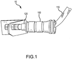
- Hose attachment system 10 may comprise hose guide 100.
- Hose guide 100 may be coupled to hose 110.
- Hose 110 is coupled to hose fittings 120.
- hose 110 may be a hydraulic hose.
- Manufacturer specifications for hose 110 may recommend that hose 110 not substantially bend within a defined distance of hose fittings 120.
- specifications may recommend that hose 110 remains substantially straight within one diameter of hose fittings 120. In other words, if hose 110 has a diameter of one inch (2.54cm), hose 110 must remain substantially straight within one inch of hose fittings 120.
- hose 110 must remain substantially straight within one-half of the diameter of hose 110, or within two diameters of hose 110. In various embodiments, hose 110 may be defined as substantially straight if hose 110 bends less than one degree, or less than five degrees.
- Hose guide 100 comprises a straight section 102 and a bell section 104.
- Straight section 102 is be configured to keep a hose 110 substantially straight within straight section 102.
- a radially outer outside diameter of outer surface 106 of hose guide 100 measured at straight section 102 may be of constant and/or substantially constant radius as one travels axially along axis A in straight section 102.
- a radially outer outside diameter of outer surface 106 of hose guide 100 measured at bell section 104 may be of varying and/or variable radius as one travels axially along axis A in bell section 104.
- Bell section 104 is configured to allow hose 110 to bend within the interior space of bell section 104.
- an outside diameter of hose guide 100 measured at bell section 104 may be larger than an outside diameter of hose guide 100 measured at straight section 102.
- the outside diameter measured at bell section 104 may be substantially the same as the outside diameter measured at straight section 102, or the outside diameter measured at bell section 104 may be less than the outside diameter measured at straight section 102.
- the outside diameter measured at bell section 104 may vary as one travels axially along axis A in bell section 104. In various embodiments, the outside diameter at bell section 104 is larger than the outside diameter at straight section 102.
- Hose guide 100 may further comprise one or more grooves 108 in an outer surface 106 of hose guide 100.
- Grooves 108 may be located in straight section 102, bell section 104, or in both straight section 102 and bell section 104.
- Fastening devices 113 such as wire ties or hose clamps, may be secured in grooves 108 in order to secure multiple pieces of hose guide 100 together.
- Groove walls 109 may prevent translational movement of fastening devices 113 when in place.
- hose guide 100 may comprise plastic.
- Hose guide 100 may be formed in a mold, such as an injection mold.
- hose guide 100 may comprise any material capable of preventing hose 110 from bending, such as steel, aluminum, carbon composites, copper, rubber, etc.
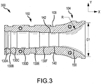
- Hose guide 100 comprises a plurality of hose fitting stages 130A, 130B, 130C, 130D, 130E, and 130F.
- the specific number and size of hose fitting stages 130A, 130B, 130C, 130D, 130E, and 130F may vary based on the intended hose and fittings to be used with hose guide 100.
- Hose guide 100 further comprises a straight hose stage 140 directly coupled to bell section 104 and axially located between bell section 104 and hose fitting stage 130F.
- hose guide 100 may prevent bending of hose 110 axially located within straight hose stage 140.
- a length of straight hose stage 140 may be selected based on specifications for hose 110 describing a minimum distance from the hose fittings that hose 110 must remain substantially straight. For example, specifications may recommend that hose 110 remain substantially straight within one inch of hose fittings 120.
- straight hose stage 140 may be at least one inch long in such embodiments.
- a diameter of straight hose stage 140 may be substantially equal to a diameter of hose 110.
- the diameter of straight hose stage 140 may be slightly greater than the diameter of hose 110, such as 1-2% greater or 5-10% greater, in order to ensure that hose guide 100 may fit around hose 110.
- An interior surface 142 of straight hose stage 140 may contact hose 110 to prevent hose 110 from bending when positioned in straight hose stage 140.
- Hose guide 100 further comprises bell stage 150.
- bell stage 150 an inside diameter D1 of hose guide 100 increases with an increase in the x-direction away from straight section 102.
- a profile of bell stage 150 is curved with a radius R. Radius R corresponds to a minimum bend radius for hose 110.
- bell stage 150 allows hose 110 to bend, but prevents hose 110 from bending at a radius less than radius R.
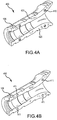
- hose guide 100 may comprise a two-piece construction. However, in various embodiments, hose guide 100 may comprise a single piece, or three or more pieces. In various embodiments, hose guide 100 may comprise a single piece which may be formed around a hose at the time that fittings are attached to the hose.
- First piece 400 may comprise alignment pegs 410. Alignment pegs 410 may extend from mating surfaces 420 of first piece 400. Alignment pegs 410 may be configured to align with alignment holes 411 on second piece 450.
- Alignment pegs 410 may be inserted into alignment holes 411, thus aligning first piece 400 with second piece 450.
- Fasteners may be placed in grooves 108 to secure first piece 400 to second piece 450.
- first piece 400 may be secured to second piece 450 using screws, bolts, snaps, clips, an adhesive, or any other method for coupling first piece 400 to second piece 450.
- First piece 400 and second piece 450 may be coupled together around hose 110 and hose fittings 120.
- First piece 400 and second piece 450 may mate together to form an inner cavity.
- the inner cavity may comprise hose fitting stages 130A through 130F, straight hose stage 140, and bell stage 150 as described with reference to FIG. 3 .
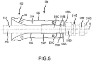
- First piece 500 may comprise bell section 502, and straight section 504.
- First piece 500 may further comprise hose fitting stages 530A, 530B, 530C, and 530D.
- first piece 500 comprises four hose fitting stages.
- first piece 500 may comprise any number of hose fitting stages.
- First piece 500 may further comprise straight hose stage 540 directly coupled to bell section 502 and axially located between bell section 502 and hose fitting stage 530D.
- Hose 510 may comprise free section 512, constrained section 514, and fittings 516A, 516B, 516C, 516D, 516E, 516F, and 516G.
- Free section 512 may be permitted to bend within bell section 502.
- bell section 502 may prevent free section 512 from bending at a radius less than a radius R2 of bell section 502.
- Straight section 504 may prevent constrained section 514 from substantially bending.
- straight section 504 may prevent damage to hose 510 at constrained section 514, where hose 510 may be susceptible to damage from bending.
- Hose fittings 516A, 516B, 516C, 516D, 516E, 516F, and 516G may comprise any type of hose fittings which may be attached to a hose.
- hose fittings 516A, 516B, 516C, 516D, 516E, 516F, and 516G may be swaged onto hose 510.
- hose fittings 516A, 516B, 516C, 516D, 516E, 516F, and 516G may be located within first piece 500, and at least one of hose fittings 516A, 516B, 516C, 516D, 516E, 516F, and 516G may be located axially exterior of first piece 500.
- Hose fitting 516A may be located in hose fitting stage 530A
- hose fitting 516B may be located in hose fitting stage 530B
- hose fitting 516C may be located in hose fitting stages 530C and 530D.
- Hose fitting stages 530A, 530B, 530C, and 530D may be designed such that first piece 500 may accommodate a plurality of hose fitting types. Different diameters of the various hose fitting stages 530A, 530B, 530C, and 530D may prevent translational movement along axis B of hose 510 within first piece 500. For example, hose fitting stages 530A and 530C may have a diameter less than hose fitting stage 530B and hose fitting 516B. Thus, hose fitting stages 530A and 530C may contact hose fitting 516B and prevent translational movement of hose 510 within first piece 500.
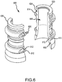
- Hose guide 600 may comprise first piece 620 and second piece 630.
- an interior section 640 is the same as that of hose guide 100, as described with reference to FIG. 3 .
- bolt lugs 610 may be coupled to first piece 620 and second piece 630.
- bolt lugs 610 may be integrally formed with first piece 620 and second piece 630.
- bolt lug mating surfaces 614 may be flush with first piece mating surfaces 624.
- first piece 620 may further comprise alignment holes 650, which may align with corresponding alignment pegs on second piece 630 in order to assist with aligning first piece 620 and second piece 630.
- bolt lugs 610 may define bolt holes 612.
- a fastening device such as a bolt 660 may be inserted through a bolt hole 612 on first piece 620 and through a corresponding bolt hole 612 on second piece 630.
- first piece 620 and second piece 630 may be coupled around a hose using bolts.
- additional fastening devices such as zip ties or wires may be used to couple first piece 620 to second piece 630.
- references to "various embodiments”, “one embodiment”, “an embodiment”, “an example embodiment”, etc. indicate that the embodiment described may include a particular feature, structure, or characteristic, but every embodiment may not necessarily include the particular feature, structure, or characteristic. Moreover, such phrases are not necessarily referring to the same embodiment. Further, when a particular feature, structure, or characteristic is described in connection with an embodiment, it is submitted that it is within the knowledge of one skilled in the art to affect such feature, structure, or characteristic in connection with other embodiments whether or not explicitly described.
- the terms “comprises”, “comprising”, or any other variation thereof, are intended to cover a non-exclusive inclusion, such that a process, method, article, or apparatus that comprises a list of elements does not include only those elements but may include other elements not expressly listed or inherent to such process, method, article, or apparatus.
Landscapes
- Engineering & Computer Science (AREA)
- General Engineering & Computer Science (AREA)
- Mechanical Engineering (AREA)
- Supports For Pipes And Cables (AREA)
Claims (15)
- Schlauchführung (100), die Folgendes umfasst:einen geraden Bereich (102), der sechs Schlauchanschlussarmaturen (130A-130F), die zueinander benachbart sind, und eine gerade Schlaucharmatur (140), die zu der sechsten Anschlussarmatur (130F) benachbart ist, umfasst; undeinen Glockenbereich (104), der direkt mit dem gerade Bereich (102) gekoppelt und daran axial ausgerichtet ist, wobei der Glockenbereich (104) ein gekrümmtes Innenprofil umfasst;wobei die sechste Anschlussarmatur (130F) einen größeren Innendurchmesser aufweist als die zu ihr benachbarte gerade Schlaucharmatur (140), wobei die fünfte Anschlussarmatur (130E) einen größeren Innendurchmesser aufweist, als die zu ihr benachbarte sechste Anschlussarmatur (130F), wobei die vierte Anschlussarmatur (130D) einen größeren Innendurchmesser aufweist als die zu ihr benachbarte fünfte Anschlussarmatur (130E), wobei die dritte Anschlussarmatur (130C) einen kleineren Innendurchmesser aufweist als die zu ihr benachbarte vierte Anschlussarmatur (130D), wobei die zweite Anschlussarmatur (130B) einen größeren Innendurchmesser aufweist als die zu ihr benachbarte dritte Anschlussarmatur (130C), wobei die erste Anschlussarmatur (130A) einen kleineren Innendurchmesser aufweist als die zu ihr benachbarte zweite Anschlussarmatur (130B);wobei der Innendurchmesser der ersten, dritten und fünften Anschlussarmatur (130A, 130C, 130E) einander gleich sind, undwobei der Innendurchmesser der vierten Anschlussarmatur (130D) kleiner als der Innendurchmesser der zweiten Anschlussarmatur (130B), jedoch größer als der Innendurchmesser der ersten Anschlussarmatur (130A) ist; undwobei der gerade Bereich (102) dazu konfiguriert ist, zu verhindern, dass ein Schlauch (110) sich innerhalb des geraden Bereichs (102) biegt; undwobei das gekrümmte Innenprofil dazu konfiguriert ist, einem Mindestbiegeradius (R) des Schlauchs (110) zu entsprechen.
- Schlauchführung nach Anspruch 1, ferner umfassend eine oder mehrere Nuten (108) in einer Außenfläche der Schlauchführung (100).
- Schlauchführung nach Anspruch 2, ferner umfassend ein oder mehrere Befestigungsmittel, die in der einen oder den mehreren Nuten (108) positioniert sind.
- Schlauchführung nach einem der vorhergehenden Ansprüche, wobei die Schlauchführung (100) ein erstes Teil (400; 620), das ein erstes Befestigungselement (410; 610) einschließt, und ein zweites Teil (450; 630), das ein zweites Befestigungselement (411; 610) einschließt, umfasst, und wobei das erste Teil (400; 620) und das zweite Teil (450; 630) dazu konfiguriert sind, mit einer Befestigungsvorrichtung (113; 612; 660) zusammengekoppelt zu werden, die das erste und das zweite Befestigungselement (410; 411; 610) koppelt.
- Schlauchführung nach einem der Ansprüche 1, 2 oder 3, ferner umfassend ein erstes Teil (400; 620) und ein zweites Teil (450; 630), wobei ein oder mehrere Befestigungsmittel (113; 612; 660) das erste Teil (400; 620) an das zweite Teil (450; 630) koppeln.
- Schlauchführung nach Anspruch 5, wobei das erste Teil (400; 620) einen Ausrichtungszapfen (410) umfasst.
- Schlauchführung nach Anspruch 6, wobei der Ausrichtungszapfen (410) innerhalb einer Ausrichtungsöffnung (411) in dem zweiten Teil (450; 630) positioniert ist.
- Schlauchführung nach einem der vorhergehenden Ansprüche, wobei ein Außendurchmesser des Glockenbereichs (104) größer ist als ein Außendurchmesser des geraden Bereichs (102; 504).
- Schlauchführung (100) nach Anspruch 1, ferner umfassend:ein erstes Teil (400; 620); undein zweites Teil (450; 630), das an das erste Teil (400; 620) gekoppelt ist, wobei das erste Teil (400; 620) und das zweite Teil (450; 630) einen Innenhohlraum bilden, der die sechs Schlauchanschlussarmaturen (130A-130F), die gerade Schlaucharmatur (140) und den Glockenbereich (104) umfasst.
- Schlauchführung nach Anspruch 9, wobei ein Innendurchmesser des Glockenbereichs (104) mit einem zunehmenden Abstand von den sechs Schlauchanschlussarmaturen (130A-130F) zunimmt.
- Schlauchführung nach Anspruch 9 oder 10, ferner umfassend ein Befestigungsmittel (113), das in einer Nut (108) in dem ersten Teil (400; 620) und dem zweiten Teil (450; 630) positioniert ist.
- Schlauchführung nach Anspruch 9, 10 oder 11, wobei das erste Teil (400; 620) einen Ausrichtungszapfen (410) umfasst, der innerhalb einer Ausrichtungsöffnung (411) in dem zweiten Teil (450; 630) positioniert ist.
- Schlauchanbringungssystem, das Folgendes umfasst:einen Schlauch (110) mit einem Mindestbiegeradius;einen Anschluss (120), der an den Schlauch (110) gekoppelt ist; undeine Schlauchführung (100) nach Anspruch 1, wobei die sechs Schlauchanschlussarmaturen (130A-130F) um den Anschluss (120) positioniert sind, wobei die gerade Schlaucharmatur (140) dazu konfiguriert ist, zu verhindern, dass der Schlauch (110) sich biegt, und wobei der Glockenabschnitt (104) dazu konfiguriert ist, es dem Schlauch (110) zu ermöglichen, sich zu biegen, jedoch zu verhindern, dass der Schlauch (110) sich in einem Radius biegt, der kleiner als der Mindestbiegeradius (R) des Schlauchs (110) ist.
- Schlauchanbringungssystem nach Anspruch 13, ferner umfassend ein Befestigungsmittel (113), das in einer Nut (108) in einer Außenfläche der Schlauchführung (100) positioniert ist.
- Schlauchanbringungssystem nach Anspruch 13 und 14, wobei die Schlauchführung (100) ein erstes Teil (400; 620) und ein zweites Teil (450; 630), das um den Schlauch (110) und den Anschluss (120) gekoppelt ist, umfasst.
Applications Claiming Priority (1)
| Application Number | Priority Date | Filing Date | Title |
|---|---|---|---|
| US13/957,368 US9651181B2 (en) | 2013-08-01 | 2013-08-01 | Hydraulic hose guide |
Publications (2)
| Publication Number | Publication Date |
|---|---|
| EP2833044A1 EP2833044A1 (de) | 2015-02-04 |
| EP2833044B1 true EP2833044B1 (de) | 2018-12-26 |
Family
ID=50842152
Family Applications (1)
| Application Number | Title | Priority Date | Filing Date |
|---|---|---|---|
| EP14170817.2A Active EP2833044B1 (de) | 2013-08-01 | 2014-06-02 | Hydraulische Schlauchführung |
Country Status (2)
| Country | Link |
|---|---|
| US (1) | US9651181B2 (de) |
| EP (1) | EP2833044B1 (de) |
Families Citing this family (9)
| Publication number | Priority date | Publication date | Assignee | Title |
|---|---|---|---|---|
| GB2558815A (en) * | 2015-11-18 | 2018-07-18 | Halliburton Energy Services Inc | Segmented bend-limiter for slickline rope sockets and cable-heads |
| JP6416743B2 (ja) * | 2015-12-11 | 2018-10-31 | 日本フルハーフ株式会社 | 油圧ホース接続部構造 |
| GB2550933B (en) * | 2016-06-01 | 2019-01-16 | Taylor Kerr Couplings Ltd | Self-aligning pipe coupling |
| CN106151771B (zh) * | 2016-07-04 | 2018-04-03 | 燕山大学 | 一种波纹金属软管管端防护装置 |
| AU201713589S (en) * | 2016-12-16 | 2017-06-27 | Rehau Ag & Co | Component for fluid distribution equipment |
| US10662948B2 (en) * | 2017-06-13 | 2020-05-26 | HELLA GmbH & Co. KGaA | Expansion chamber for a brake boost vacuum pump |
| US10837158B2 (en) * | 2018-02-07 | 2020-11-17 | Manitou Equipment America, Llc | Loader, operator seat assembly with integrated, non-electronic hydraulic pilot valves |
| USD940974S1 (en) * | 2018-05-31 | 2022-01-11 | Camco Manufacturing, Llc | Swivel stick adapter |
| US12562558B2 (en) * | 2024-01-25 | 2026-02-24 | Panduit Corp. | Segmented bend restrictor system with full disassembly capability |
Family Cites Families (8)
| Publication number | Priority date | Publication date | Assignee | Title |
|---|---|---|---|---|
| US1844023A (en) | 1929-01-02 | 1932-02-09 | Cash A W Co | Hose clamp |
| US1970050A (en) * | 1932-09-03 | 1934-08-14 | Ferdinand A Mathey | Hose coupling |
| US2295830A (en) | 1940-11-26 | 1942-09-15 | Scovill Manufacturing Co | Hose coupling |
| GB643615A (en) | 1948-05-05 | 1950-09-20 | Weeks & Son Ltd W | Improvements in hose clamps |
| IT1184604B (it) | 1985-06-11 | 1987-10-28 | Luisa Epis | Struttura di copertura per raccordi particolarmente di radiatori e simili |
| US5853200A (en) * | 1996-04-15 | 1998-12-29 | Gary A. Zieres | Hose coupling boot |
| GB9703144D0 (en) * | 1997-02-14 | 1997-04-02 | Tyrer Andrew C R | Bend stiffeners |
| US9163463B2 (en) * | 2011-06-01 | 2015-10-20 | Deep Down, Inc. | Bend limiting stiffener and related methods |
-
2013
- 2013-08-01 US US13/957,368 patent/US9651181B2/en active Active
-
2014
- 2014-06-02 EP EP14170817.2A patent/EP2833044B1/de active Active
Non-Patent Citations (1)
| Title |
|---|
| None * |
Also Published As
| Publication number | Publication date |
|---|---|
| EP2833044A1 (de) | 2015-02-04 |
| US20150035271A1 (en) | 2015-02-05 |
| US9651181B2 (en) | 2017-05-16 |
Similar Documents
| Publication | Publication Date | Title |
|---|---|---|
| EP2833044B1 (de) | Hydraulische Schlauchführung | |
| US8342474B2 (en) | Modular support, assemblies, methods and systems | |
| EP2923134B1 (de) | Abdichtungssystem | |
| JP6347530B2 (ja) | 弧状剛性リブを有する継手 | |
| CN105518366B (zh) | 快速锁定管固定系统 | |
| JP5523558B2 (ja) | 成形ロッド結合システム | |
| SE443436B (sv) | Fluidkoppling | |
| US10385992B2 (en) | Modular buoyancy element | |
| KR101835614B1 (ko) | 고무튜브를 이용한 클램프형 다중 케이블 | |
| KR101408807B1 (ko) | 진공배관용 주름관 및 이와 파이프의 결합구조체 | |
| GB2544075A (en) | Improvements relating to bend restrictors | |
| US20170107770A1 (en) | Interface | |
| US11441703B2 (en) | Conduit alignment tool with wings | |
| WO2015196249A1 (en) | Modular pipe systems and components | |
| EP3440392B1 (de) | Führungsvorrichtung | |
| KR20110011340U (ko) | 호스 연결부의 분리방지용 연결 클램프 | |
| WO2017072316A1 (en) | A coupling system and a method for coupling two pipe ends | |
| CA3037479C (en) | Clip-based non-metallic fittings for attachment of flexible metallic conduit | |
| US11939822B2 (en) | Control line protector assembly | |
| US9404617B2 (en) | Clamp | |
| CN103133802A (zh) | 用于连接柔性管道的防旋转缆绳限制器 | |
| KR101303062B1 (ko) | 합성수지관 연결장치 | |
| KR101409246B1 (ko) | 일체형 광케이블 보호관의 연결장치 | |
| US8967676B1 (en) | Two-piece split coupler for coupling large-diameter plastic corrugated pipe | |
| KR20070015069A (ko) | 덕트 |
Legal Events
| Date | Code | Title | Description |
|---|---|---|---|
| 17P | Request for examination filed |
Effective date: 20140602 |
|
| AK | Designated contracting states |
Kind code of ref document: A1 Designated state(s): AL AT BE BG CH CY CZ DE DK EE ES FI FR GB GR HR HU IE IS IT LI LT LU LV MC MK MT NL NO PL PT RO RS SE SI SK SM TR |
|
| AX | Request for extension of the european patent |
Extension state: BA ME |
|
| PUAI | Public reference made under article 153(3) epc to a published international application that has entered the european phase |
Free format text: ORIGINAL CODE: 0009012 |
|
| R17P | Request for examination filed (corrected) |
Effective date: 20150803 |
|
| RBV | Designated contracting states (corrected) |
Designated state(s): AL AT BE BG CH CY CZ DE DK EE ES FI FR GB GR HR HU IE IS IT LI LT LU LV MC MK MT NL NO PL PT RO RS SE SI SK SM TR |
|
| STAA | Information on the status of an ep patent application or granted ep patent |
Free format text: STATUS: EXAMINATION IS IN PROGRESS |
|
| 17Q | First examination report despatched |
Effective date: 20171013 |
|
| GRAP | Despatch of communication of intention to grant a patent |
Free format text: ORIGINAL CODE: EPIDOSNIGR1 |
|
| STAA | Information on the status of an ep patent application or granted ep patent |
Free format text: STATUS: GRANT OF PATENT IS INTENDED |
|
| INTG | Intention to grant announced |
Effective date: 20180720 |
|
| GRAS | Grant fee paid |
Free format text: ORIGINAL CODE: EPIDOSNIGR3 |
|
| GRAA | (expected) grant |
Free format text: ORIGINAL CODE: 0009210 |
|
| STAA | Information on the status of an ep patent application or granted ep patent |
Free format text: STATUS: THE PATENT HAS BEEN GRANTED |
|
| AK | Designated contracting states |
Kind code of ref document: B1 Designated state(s): AL AT BE BG CH CY CZ DE DK EE ES FI FR GB GR HR HU IE IS IT LI LT LU LV MC MK MT NL NO PL PT RO RS SE SI SK SM TR |
|
| REG | Reference to a national code |
Ref country code: GB Ref legal event code: FG4D |
|
| REG | Reference to a national code |
Ref country code: CH Ref legal event code: EP |
|
| REG | Reference to a national code |
Ref country code: AT Ref legal event code: REF Ref document number: 1081885 Country of ref document: AT Kind code of ref document: T Effective date: 20190115 |
|
| REG | Reference to a national code |
Ref country code: DE Ref legal event code: R096 Ref document number: 602014038494 Country of ref document: DE |
|
| REG | Reference to a national code |
Ref country code: IE Ref legal event code: FG4D |
|
| PG25 | Lapsed in a contracting state [announced via postgrant information from national office to epo] |
Ref country code: FI Free format text: LAPSE BECAUSE OF FAILURE TO SUBMIT A TRANSLATION OF THE DESCRIPTION OR TO PAY THE FEE WITHIN THE PRESCRIBED TIME-LIMIT Effective date: 20181226 Ref country code: NO Free format text: LAPSE BECAUSE OF FAILURE TO SUBMIT A TRANSLATION OF THE DESCRIPTION OR TO PAY THE FEE WITHIN THE PRESCRIBED TIME-LIMIT Effective date: 20190326 Ref country code: HR Free format text: LAPSE BECAUSE OF FAILURE TO SUBMIT A TRANSLATION OF THE DESCRIPTION OR TO PAY THE FEE WITHIN THE PRESCRIBED TIME-LIMIT Effective date: 20181226 Ref country code: LT Free format text: LAPSE BECAUSE OF FAILURE TO SUBMIT A TRANSLATION OF THE DESCRIPTION OR TO PAY THE FEE WITHIN THE PRESCRIBED TIME-LIMIT Effective date: 20181226 Ref country code: BG Free format text: LAPSE BECAUSE OF FAILURE TO SUBMIT A TRANSLATION OF THE DESCRIPTION OR TO PAY THE FEE WITHIN THE PRESCRIBED TIME-LIMIT Effective date: 20190326 Ref country code: LV Free format text: LAPSE BECAUSE OF FAILURE TO SUBMIT A TRANSLATION OF THE DESCRIPTION OR TO PAY THE FEE WITHIN THE PRESCRIBED TIME-LIMIT Effective date: 20181226 |
|
| REG | Reference to a national code |
Ref country code: NL Ref legal event code: MP Effective date: 20181226 |
|
| REG | Reference to a national code |
Ref country code: LT Ref legal event code: MG4D |
|
| PG25 | Lapsed in a contracting state [announced via postgrant information from national office to epo] |
Ref country code: AL Free format text: LAPSE BECAUSE OF FAILURE TO SUBMIT A TRANSLATION OF THE DESCRIPTION OR TO PAY THE FEE WITHIN THE PRESCRIBED TIME-LIMIT Effective date: 20181226 Ref country code: SE Free format text: LAPSE BECAUSE OF FAILURE TO SUBMIT A TRANSLATION OF THE DESCRIPTION OR TO PAY THE FEE WITHIN THE PRESCRIBED TIME-LIMIT Effective date: 20181226 Ref country code: RS Free format text: LAPSE BECAUSE OF FAILURE TO SUBMIT A TRANSLATION OF THE DESCRIPTION OR TO PAY THE FEE WITHIN THE PRESCRIBED TIME-LIMIT Effective date: 20181226 Ref country code: GR Free format text: LAPSE BECAUSE OF FAILURE TO SUBMIT A TRANSLATION OF THE DESCRIPTION OR TO PAY THE FEE WITHIN THE PRESCRIBED TIME-LIMIT Effective date: 20190327 |
|
| REG | Reference to a national code |
Ref country code: AT Ref legal event code: MK05 Ref document number: 1081885 Country of ref document: AT Kind code of ref document: T Effective date: 20181226 |
|
| PG25 | Lapsed in a contracting state [announced via postgrant information from national office to epo] |
Ref country code: NL Free format text: LAPSE BECAUSE OF FAILURE TO SUBMIT A TRANSLATION OF THE DESCRIPTION OR TO PAY THE FEE WITHIN THE PRESCRIBED TIME-LIMIT Effective date: 20181226 |
|
| PG25 | Lapsed in a contracting state [announced via postgrant information from national office to epo] |
Ref country code: CZ Free format text: LAPSE BECAUSE OF FAILURE TO SUBMIT A TRANSLATION OF THE DESCRIPTION OR TO PAY THE FEE WITHIN THE PRESCRIBED TIME-LIMIT Effective date: 20181226 Ref country code: IT Free format text: LAPSE BECAUSE OF FAILURE TO SUBMIT A TRANSLATION OF THE DESCRIPTION OR TO PAY THE FEE WITHIN THE PRESCRIBED TIME-LIMIT Effective date: 20181226 Ref country code: PL Free format text: LAPSE BECAUSE OF FAILURE TO SUBMIT A TRANSLATION OF THE DESCRIPTION OR TO PAY THE FEE WITHIN THE PRESCRIBED TIME-LIMIT Effective date: 20181226 Ref country code: ES Free format text: LAPSE BECAUSE OF FAILURE TO SUBMIT A TRANSLATION OF THE DESCRIPTION OR TO PAY THE FEE WITHIN THE PRESCRIBED TIME-LIMIT Effective date: 20181226 Ref country code: PT Free format text: LAPSE BECAUSE OF FAILURE TO SUBMIT A TRANSLATION OF THE DESCRIPTION OR TO PAY THE FEE WITHIN THE PRESCRIBED TIME-LIMIT Effective date: 20190426 |
|
| PG25 | Lapsed in a contracting state [announced via postgrant information from national office to epo] |
Ref country code: EE Free format text: LAPSE BECAUSE OF FAILURE TO SUBMIT A TRANSLATION OF THE DESCRIPTION OR TO PAY THE FEE WITHIN THE PRESCRIBED TIME-LIMIT Effective date: 20181226 Ref country code: SM Free format text: LAPSE BECAUSE OF FAILURE TO SUBMIT A TRANSLATION OF THE DESCRIPTION OR TO PAY THE FEE WITHIN THE PRESCRIBED TIME-LIMIT Effective date: 20181226 Ref country code: IS Free format text: LAPSE BECAUSE OF FAILURE TO SUBMIT A TRANSLATION OF THE DESCRIPTION OR TO PAY THE FEE WITHIN THE PRESCRIBED TIME-LIMIT Effective date: 20190426 Ref country code: RO Free format text: LAPSE BECAUSE OF FAILURE TO SUBMIT A TRANSLATION OF THE DESCRIPTION OR TO PAY THE FEE WITHIN THE PRESCRIBED TIME-LIMIT Effective date: 20181226 Ref country code: SK Free format text: LAPSE BECAUSE OF FAILURE TO SUBMIT A TRANSLATION OF THE DESCRIPTION OR TO PAY THE FEE WITHIN THE PRESCRIBED TIME-LIMIT Effective date: 20181226 |
|
| REG | Reference to a national code |
Ref country code: DE Ref legal event code: R097 Ref document number: 602014038494 Country of ref document: DE |
|
| PG25 | Lapsed in a contracting state [announced via postgrant information from national office to epo] |
Ref country code: AT Free format text: LAPSE BECAUSE OF FAILURE TO SUBMIT A TRANSLATION OF THE DESCRIPTION OR TO PAY THE FEE WITHIN THE PRESCRIBED TIME-LIMIT Effective date: 20181226 Ref country code: DK Free format text: LAPSE BECAUSE OF FAILURE TO SUBMIT A TRANSLATION OF THE DESCRIPTION OR TO PAY THE FEE WITHIN THE PRESCRIBED TIME-LIMIT Effective date: 20181226 |
|
| PLBE | No opposition filed within time limit |
Free format text: ORIGINAL CODE: 0009261 |
|
| STAA | Information on the status of an ep patent application or granted ep patent |
Free format text: STATUS: NO OPPOSITION FILED WITHIN TIME LIMIT |
|
| 26N | No opposition filed |
Effective date: 20190927 |
|
| REG | Reference to a national code |
Ref country code: DE Ref legal event code: R119 Ref document number: 602014038494 Country of ref document: DE |
|
| PG25 | Lapsed in a contracting state [announced via postgrant information from national office to epo] |
Ref country code: MC Free format text: LAPSE BECAUSE OF FAILURE TO SUBMIT A TRANSLATION OF THE DESCRIPTION OR TO PAY THE FEE WITHIN THE PRESCRIBED TIME-LIMIT Effective date: 20181226 |
|
| REG | Reference to a national code |
Ref country code: CH Ref legal event code: PL |
|
| PG25 | Lapsed in a contracting state [announced via postgrant information from national office to epo] |
Ref country code: SI Free format text: LAPSE BECAUSE OF FAILURE TO SUBMIT A TRANSLATION OF THE DESCRIPTION OR TO PAY THE FEE WITHIN THE PRESCRIBED TIME-LIMIT Effective date: 20181226 |
|
| REG | Reference to a national code |
Ref country code: BE Ref legal event code: MM Effective date: 20190630 |
|
| PG25 | Lapsed in a contracting state [announced via postgrant information from national office to epo] |
Ref country code: TR Free format text: LAPSE BECAUSE OF FAILURE TO SUBMIT A TRANSLATION OF THE DESCRIPTION OR TO PAY THE FEE WITHIN THE PRESCRIBED TIME-LIMIT Effective date: 20181226 |
|
| PG25 | Lapsed in a contracting state [announced via postgrant information from national office to epo] |
Ref country code: IE Free format text: LAPSE BECAUSE OF NON-PAYMENT OF DUE FEES Effective date: 20190602 Ref country code: DE Free format text: LAPSE BECAUSE OF NON-PAYMENT OF DUE FEES Effective date: 20200101 |
|
| PG25 | Lapsed in a contracting state [announced via postgrant information from national office to epo] |
Ref country code: LU Free format text: LAPSE BECAUSE OF NON-PAYMENT OF DUE FEES Effective date: 20190602 Ref country code: CH Free format text: LAPSE BECAUSE OF NON-PAYMENT OF DUE FEES Effective date: 20190630 Ref country code: BE Free format text: LAPSE BECAUSE OF NON-PAYMENT OF DUE FEES Effective date: 20190630 Ref country code: LI Free format text: LAPSE BECAUSE OF NON-PAYMENT OF DUE FEES Effective date: 20190630 |
|
| PG25 | Lapsed in a contracting state [announced via postgrant information from national office to epo] |
Ref country code: CY Free format text: LAPSE BECAUSE OF FAILURE TO SUBMIT A TRANSLATION OF THE DESCRIPTION OR TO PAY THE FEE WITHIN THE PRESCRIBED TIME-LIMIT Effective date: 20181226 |
|
| PG25 | Lapsed in a contracting state [announced via postgrant information from national office to epo] |
Ref country code: MT Free format text: LAPSE BECAUSE OF FAILURE TO SUBMIT A TRANSLATION OF THE DESCRIPTION OR TO PAY THE FEE WITHIN THE PRESCRIBED TIME-LIMIT Effective date: 20181226 Ref country code: HU Free format text: LAPSE BECAUSE OF FAILURE TO SUBMIT A TRANSLATION OF THE DESCRIPTION OR TO PAY THE FEE WITHIN THE PRESCRIBED TIME-LIMIT; INVALID AB INITIO Effective date: 20140602 |
|
| PG25 | Lapsed in a contracting state [announced via postgrant information from national office to epo] |
Ref country code: MK Free format text: LAPSE BECAUSE OF FAILURE TO SUBMIT A TRANSLATION OF THE DESCRIPTION OR TO PAY THE FEE WITHIN THE PRESCRIBED TIME-LIMIT Effective date: 20181226 |
|
| P01 | Opt-out of the competence of the unified patent court (upc) registered |
Effective date: 20230522 |
|
| PGFP | Annual fee paid to national office [announced via postgrant information from national office to epo] |
Ref country code: GB Payment date: 20250520 Year of fee payment: 12 |
|
| PGFP | Annual fee paid to national office [announced via postgrant information from national office to epo] |
Ref country code: FR Payment date: 20250520 Year of fee payment: 12 |