EP3440392B1 - Führungsvorrichtung - Google Patents
Führungsvorrichtung Download PDFInfo
- Publication number
- EP3440392B1 EP3440392B1 EP17721795.7A EP17721795A EP3440392B1 EP 3440392 B1 EP3440392 B1 EP 3440392B1 EP 17721795 A EP17721795 A EP 17721795A EP 3440392 B1 EP3440392 B1 EP 3440392B1
- Authority
- EP
- European Patent Office
- Prior art keywords
- elements
- link members
- members
- elongate member
- guide apparatus
- Prior art date
- Legal status (The legal status is an assumption and is not a legal conclusion. Google has not performed a legal analysis and makes no representation as to the accuracy of the status listed.)
- Active
Links
Images


Classifications
-
- F—MECHANICAL ENGINEERING; LIGHTING; HEATING; WEAPONS; BLASTING
- F16—ENGINEERING ELEMENTS AND UNITS; GENERAL MEASURES FOR PRODUCING AND MAINTAINING EFFECTIVE FUNCTIONING OF MACHINES OR INSTALLATIONS; THERMAL INSULATION IN GENERAL
- F16L—PIPES; JOINTS OR FITTINGS FOR PIPES; SUPPORTS FOR PIPES, CABLES OR PROTECTIVE TUBING; MEANS FOR THERMAL INSULATION IN GENERAL
- F16L3/00—Supports for pipes, cables or protective tubing, e.g. hangers, holders, clamps, cleats, clips, brackets
- F16L3/01—Supports for pipes, cables or protective tubing, e.g. hangers, holders, clamps, cleats, clips, brackets for supporting or guiding the pipes, cables or protective tubing, between relatively movable points, e.g. movable channels
- F16L3/015—Supports for pipes, cables or protective tubing, e.g. hangers, holders, clamps, cleats, clips, brackets for supporting or guiding the pipes, cables or protective tubing, between relatively movable points, e.g. movable channels using articulated- or supple-guiding elements
-
- F—MECHANICAL ENGINEERING; LIGHTING; HEATING; WEAPONS; BLASTING
- F16—ENGINEERING ELEMENTS AND UNITS; GENERAL MEASURES FOR PRODUCING AND MAINTAINING EFFECTIVE FUNCTIONING OF MACHINES OR INSTALLATIONS; THERMAL INSULATION IN GENERAL
- F16L—PIPES; JOINTS OR FITTINGS FOR PIPES; SUPPORTS FOR PIPES, CABLES OR PROTECTIVE TUBING; MEANS FOR THERMAL INSULATION IN GENERAL
- F16L57/00—Protection of pipes or objects of similar shape against external or internal damage or wear
- F16L57/02—Protection of pipes or objects of similar shape against external or internal damage or wear against cracking or buckling
-
- F—MECHANICAL ENGINEERING; LIGHTING; HEATING; WEAPONS; BLASTING
- F16—ENGINEERING ELEMENTS AND UNITS; GENERAL MEASURES FOR PRODUCING AND MAINTAINING EFFECTIVE FUNCTIONING OF MACHINES OR INSTALLATIONS; THERMAL INSULATION IN GENERAL
- F16L—PIPES; JOINTS OR FITTINGS FOR PIPES; SUPPORTS FOR PIPES, CABLES OR PROTECTIVE TUBING; MEANS FOR THERMAL INSULATION IN GENERAL
- F16L1/00—Laying or reclaiming pipes; Repairing or joining pipes on or under water
- F16L1/12—Laying or reclaiming pipes on or under water
- F16L1/123—Devices for the protection of pipes under water
-
- F—MECHANICAL ENGINEERING; LIGHTING; HEATING; WEAPONS; BLASTING
- F16—ENGINEERING ELEMENTS AND UNITS; GENERAL MEASURES FOR PRODUCING AND MAINTAINING EFFECTIVE FUNCTIONING OF MACHINES OR INSTALLATIONS; THERMAL INSULATION IN GENERAL
- F16L—PIPES; JOINTS OR FITTINGS FOR PIPES; SUPPORTS FOR PIPES, CABLES OR PROTECTIVE TUBING; MEANS FOR THERMAL INSULATION IN GENERAL
- F16L3/00—Supports for pipes, cables or protective tubing, e.g. hangers, holders, clamps, cleats, clips, brackets
- F16L3/08—Supports for pipes, cables or protective tubing, e.g. hangers, holders, clamps, cleats, clips, brackets substantially surrounding the pipe, cable or protective tubing
-
- F—MECHANICAL ENGINEERING; LIGHTING; HEATING; WEAPONS; BLASTING
- F16—ENGINEERING ELEMENTS AND UNITS; GENERAL MEASURES FOR PRODUCING AND MAINTAINING EFFECTIVE FUNCTIONING OF MACHINES OR INSTALLATIONS; THERMAL INSULATION IN GENERAL
- F16L—PIPES; JOINTS OR FITTINGS FOR PIPES; SUPPORTS FOR PIPES, CABLES OR PROTECTIVE TUBING; MEANS FOR THERMAL INSULATION IN GENERAL
- F16L57/00—Protection of pipes or objects of similar shape against external or internal damage or wear
Definitions
- This invention concerns a guide apparatus, and particularly a guide apparatus for an elongate member.
- US6941974 discloses a cable or the like protection and guide device including link frame members each having a rectangular section, and a pair of flexible cable-shaped members insertion-passing through the respective guide holes formed on both side walls of the link member.
- guide apparatus for an elongate member, the apparatus comprising a plurality of elements locatable adjacent each other along at least part of the length of the elongate member, with each element being extendable around the elongate member, a plurality of elongate link members being provided between adjacent elements, the link members being spaced from each other around the elements, the link members permitting limited movement apart of the respective elements, such that the apparatus permits limited bending of the elongate member, the elements are slidably movable relative to the link members, with guide formations provided on the elements, through which guide formations the link members slidably extend, characterised in that the link members are different at different parts of the apparatus, to provide different stiffnesses and/or permit different amounts of flexing of the elongate member.
- the guide formations may have a generally T-shape cross section, with a narrow opening and a wider main part to receive the link members once they have passed through the opening during formation of the apparatus.
- the link members may comprise lengths of planar material.
- the link members may extend along and between a plurality of adjacent elements. Restriction formations may be provided on the link members to restrict the amount of movement between the link members and the elements, and the restriction formations may locate between adjacent elements.
- Outwardly extending engagement members may be provided on ends of the elements, engageable against the ends of adjacent elements when the apparatus is bent, on the inside of the bend.
- engagement members are integrally formed with the remainder of the elements.
- the engagement members are in the form of a plurality of discrete members provided on the ends of each element, and the engagement members may be in the form of pads.
- the engagement members may be selectively mountable on ends of each element.
- the engagement members may be formed of a resilient material.
- the elements have a side opening such that they can be located on an elongate member, by the elongate member passing through the side opening, and the elements may be configured such that they have to be deformed to permit the elongate member to pass through the side opening.
- Adjacent elements may be orientated such that the side openings in adjacent elements are not aligned.
- Closure members may be provided locatable in the side openings once the elements are mounted on an elongate member.
- the elements define a closed loop around the elongate members, and during formation of the apparatus the elements are movable axially along an elongate member to a required position.
- the elements may be made of a plastics material, and may be made of polypropylene.
- At least four link members may be provided for each element, and five or six link members may be provided for each element.
- the elements may be formed in two parts, which parts may be identical.
- the parts may have an open configuration with a front face and inner and outer sides, and a framework of webs therebetween.
- a sleeve member may be provided locatable around the elongate member within the elements.
- the sleeve member may be formed of a softer material than the elements, a side opening may be provided in the sleeve member to permit location on an elongate member by deformation of the sleeve member.
- Spaced rims may be provided along the length of the sleeve member, such that the elements locate between respective rims.
- the sleeve member may be over moulded onto the elements.
- a respective individual sleeve member may be provided extending between each pair of adjacent elements, and formations may be provided on the elements, which formations may be in the form of steps against which ends of the individual sleeve members engage.
- the individual sleeve members may be incorporated in the elements during formation thereof, such that one side of the elements has a male form incorporating an individual sleeve member, which side is sealable adjacent a side of a further element with a female form without an individual sleeve member.
- the link members may be in the form of straps, rope or alternatively pins, and may be made of an elastic material.
- adjacent link members on each element extend in opposite directions to each other, to each connect to just one respective adjacent element.
- At least eight guide formations may be provided around each element.
- a temporary wrap may be provided around the apparatus to provide protection during installation, and the temporary wrap may be such as to degrade during use.
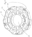
- Figs. 1 - 4 show a first element 10 of guide apparatus 12 according to the invention.
- the first element 10 is formed of two identical parts 14 which together form a hollow body as shown in Fig. 1 which defines a ring with a central opening 16 and a side opening 18 which is smaller than the diameter of the central opening 16.
- the element 10 is made of a plastics material, and in this instance polypropylene.
- each of the guide formations 20 has a substantially T-shaped cross section with a narrow opening 22 leading to a wider main part 24.
- the parts 14 are identical and are hollow with a front faces 26 and inner and outer faces 28, 30.
- Three upstanding pins 31 are provided on each part 14 locatable in respective sockets 32 on the other part 14 to locate and interconnect the two parts 14.
- Engagement members are provided on the front faces 26, in the form of five discrete projections 34, each located towards the outer face 30, equidistant between a respective adjacent pair of guide formations 20.
- the projections 34 have a gently curved face to ensure a smooth engagement as the first elements 10 come together as the apparatus 12 is bent.
- Fig. 5 shows a sleeve member 36 which is generally annular in cross section apart from a side opening 38.
- a plurality of spaced rims 40 are provided on the sleeve member 36, at distances corresponding to just greater than the thicknesses of the first elements 10.
- the sleeve member 36 is made of a softer material than the first elements 10, and may be made for example of polyurethane.
- Fig. 6 shows the first elements 10 being mounted on the sleeve member 36, with the first elements 10 locating between respective rims 40, and the side openings 18 in adjacent first elements 10 being aligned differently from each other.
- Figs. 7 and 8 shows eight such first elements 10 mounted on a respective sleeve member 36 on an elongate member 42 such as a pipeline or for example a pipe including cables or otherwise, which could be used in a wind farm or in hydrocarbon production.
- the first elements 10 are mounted with their side openings 18 not in alignment with those on adjacent first elements 10.
- link members 44 are provided, one for each of the guide formations 20 on the first elements 10, noting that the first elements 10 are orientated such that guide formations 20 on adjacent first elements 10 are aligned with each other.
- the link members 44 comprise straps which extend through the main part 24 of the respective guide formations 20, and end members 46 are provided at each end to retain the link members 44 in position relative to the end most first elements 10.
- the apparatus 12 permits limited bending of the elongate member 42, by virtue of the first elements 10 slidably movable together along the link member 44 on one side of the elongate member 42, and slidably movable apart by relative sliding movement of the first elements 10 and link members 44 on the opposite side.
- the projections 34 on adjacent first elements 10 will engage against each other, thereby limiting the amount of bending, and preventing damage or stress points on the front faces 26 of the first elements 10.
- This arrangement means that the first elements 10 are not in tension, but the bending movement is achieved by relative sliding movement between the first elements 10 and the link members 44.
- the link members 44 have some elasticity and so provide increasing amounts of resistance to bending, at the maximum limit of permitted bending.
- the sleeve member 36 being made of a softer material avoids stress points against the elongate member 42.
- the apparatus 12 may be mounted on the elongate member 42 in the following way. Initially the sleeve member 36 is mounted on the elongate member 42 by deforming the sleeve member 36 such that the elongate member 42 can pass through the side opening 38. The first elements 10 are then located on the sleeve member 36 on the elongate member 42. This is achieved by deforming the first elements 10 and the sleeve member 36, such that the elongate member 42 can pass through the side opening 18. The first elements 10 are located between respective pairs of rims 40, with guide formations 20 on adjacent first elements 10 aligned, but the side openings 38 on adjacent first elements 10 not aligned.
- the link members 44 can then be inserted into the guide formations 20 through the narrow openings 22, and may require folding to pass through the narrow openings 22, but then lay flat in the main parts 24.
- the end members 46 are then mounted by any appropriate method.
- the apparatus generally avoids areas of stress being applied to the members and/or the elongate member, by virtue of the link members and sleeve.
- the amount of bending permitted for any application is determined by the choice of link members and/or engagement members.
- the engagement members are integrally formed with the remainder of the element. If elements with more or less pronounced engagement members are required, changes can be made to the tool used to mould the elements.
- the apparatus can be customised to provide different performance along the length of an elongate member, for instance by using link members of different length and/or elasticity, and/or engagement members of different size.
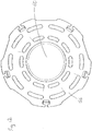
- FIGs. 9 and 10 show a second element 48 formed from two identical parts 50 in a similar way to the first element 10, but in this instance five equispaced guide formations 52 are provided,
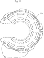
- Figs. 11 and 12 show a third element 54 made again from two identical parts 56, again with five guide formations 58.
- the third element 54 forms an unbroken ring with a central opening 60, and does not have a side opening, and will therefore require to be axially slid along an elongate member.
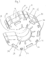
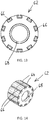
- Figs. 13 to 18 show a further arrangement with a fourth element 62 which is similar in many respects to the elements 10, 48 and 54, except as indicated.
- the fourth element 62 is again formed of two identical parts 64, and does not have a side opening.
- ten guide formations 66 are provided equispaced around the circumference of the fourth element 62.
- the guide formations 66 again have a substantially T-shaped cross section.
- a circumferential step 68 is provided on the inside of each fourth element spaced a short distance from the end to receive the end of an individual sleeve 70 which locates between each pair of fourth elements 62.
- the individual sleeves 70 are made of a softer material than the fourth element 62, and may be made for example of polyurethane.
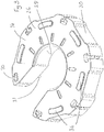
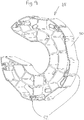
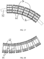
- Figs. 16 to 18 show six fourth elements 62 mounted together around an elongate member 72 such as a pipe or pipeline as previously indicated.
- link members 74 are provided in each guide formation 66, but with each link member 74 only connecting one fourth element 62 with an adjacent fourth element 62, and the link members 74 alternately interconnecting two adjacent fourth elements 62 in opposite directions, such that each pair of fourth elements 62 are interconnected by five link members 74 located in every other guide formation 66.
- the link members 74 are in the form of straps with over moulded end parts to engage against the end of a guide formation 66.
- link members 74 perform well under tension to limit the minimum bend radius.
- the individual sleeves 70 help the arrangement to bend and improve sheer resistance between the fourth elements and ensure the fourth elements pivot reliably relative to each other.
- the individual sleeves 70 may be incorporated in the parts 64 of the fourth element 62 during injection moulding thereof. This will produce a male part 76 as shown in Figs. 19 and 20 , with an individual sleeve mounted in the step 68 during manufacture.
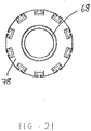
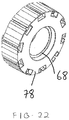
- a female part 78 is provided which is similar to the part 64, as shown in Figs. 21 and 22 , and the individual sleeve 70 on a male part 76 can be received in the step 68 on the female part 78.
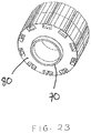
- the two parts 76, 78 can be joined together as per the identical parts 64 to form a fourth element 80 with an integral individual sleeve 70, as shown in Fig. 23 .
- the depth of the guide formations may be varied. This could be achieved by having guide formations of greater depth than as shown, and providing inserts in the formations if it is required to reduce the depth.
- the link members may take a different form, and may for instance be in the form of a rope, or pins. Restriction formations may be provided along the length of the link members locatable between adjacent elements to limit movement between adjacent members.
- link members may be provided between adjacent elements.
- Different types, or different lengths of link members are provided at different places along the apparatus, such as for instance to permit less bending of the elongate member at particular points, and for instance at end locations where the elongate member may be mountable to an article, or perhaps a further elongate member.
- the engagement members may take a different form.
- the engagement members could be bonded or attached to the elements, and the engagement members may be in the form of pads.
- the engagement members may be made of different material to the elements, and could be made of a resilient material.
- the sleeve member may be over moulded onto the inside of the elements. Where a side opening is provided in the elements, closure parts may be locatable in the side openings once mounted on an elongate member.
- a temporary wrap may be provided on the apparatus, to for instance provide protection during installation. The temporary wrap may be made of a material which will degrade in use.
Landscapes
- Engineering & Computer Science (AREA)
- General Engineering & Computer Science (AREA)
- Mechanical Engineering (AREA)
- Supports For Pipes And Cables (AREA)
- Rigid Pipes And Flexible Pipes (AREA)
Claims (15)
- Führungsvorrichtung (12) für ein längliches Element (42, 72), wobei die Vorrichtung (12) mehrere Elemente (10, 48, 54, 62) umfasst, die entlang mindestens eines Teils der Länge des länglichen Elements (42, 72) nebeneinander anordenbar sind, wobei jedes Element (10, 48, 54, 62) um das längliche Element (42, 72) erstreckbar ist, wobei mehrere benachbarte Verbindungselemente (44, 74) zwischen benachbarten Elementen (10, 48, 54, 62) vorgesehen sind, wobei die Verbindungselemente (44, 74) um die Elemente (10, 48, 54, 62) herum voneinander beabstandet sind, wobei die Verbindungselemente (44, 74) eine begrenzte Bewegung der jeweiligen Elemente (10, 48, 54, 62) voneinander weg erlauben, so dass die Vorrichtung (12) ein begrenztes Biegen des länglichen Elements (42, 72) erlaubt, wobei die Elemente (10, 48, 54, 62) relativ zu den Verbindungselementen (44, 74) verschiebbar beweglich sind, mit Führungsformationen (20, 52, 58, 66), die an den Elementen (10, 48, 54, 62) vorgesehen sind, wobei sich die Verbindungselemente (44, 74) durch die Führungsformationen (20, 52, 58, 66) verschieblich erstrecken, dadurch gekennzeichnet, dass die Verbindungselemente (44, 74) an unterschiedlichen Teilen der Vorrichtung (12) unterschiedlich sind, um unterschiedliche Steifigkeiten bereitzustellen und/oder unterschiedliche Biegungsgrade des länglichen Elements (42, 72) zu ermöglichen.
- Führungsvorrichtung (12) nach Anspruch 1, bei der die Führungsformationen (20, 52, 58, 66) einen im Wesentlichen T-förmigen Querschnitt mit einer schmalen Öffnung (22) und einem breiteren Hauptteil (24) aufweisen, um die Verbindungselemente (44, 74) aufzunehmen, sobald sie während der Bildung der Vorrichtung (12) die Öffnung (22) passiert haben.
- Führungsvorrichtung (12) nach Anspruch 1 oder 2, bei der die Verbindungselemente (44, 74) Längen von planarem Material umfassen und die Verbindungselemente (44, 74) sich entlang und zwischen mehreren benachbarten Elementen (10, 48, 54, 62) erstrecken können.
- Führungsvorrichtung (12) nach einem der vorhergehenden Ansprüche, bei der Begrenzungsformationen an den Verbindungselementen (44, 74) vorgesehen sind, um das Ausmaß der Bewegung zwischen den Verbindungselementen (44, 74) und den Elementen (10, 48, 54, 62) zu begrenzen, und wobei die Begrenzungsformationen zwischen benachbarten Elementen (10, 48, 54, 62) angeordnet sein können.
- Führungsvorrichtung (12) nach einem der vorhergehenden Ansprüche, bei der sich äußerlich erstreckende Eingriffselemente (34) an Enden der Elemente (10, 48, 54, 62) vorgesehen sind, die an der Innenseite der Biegung die Eingriffselemente (34) mit Enden benachbarter Elemente (10, 48, 54, 62) in Eingriff bringbar sind, wenn die Vorrichtung (12) gebogen ist, wobei die Eingriffselemente (34) mit dem Rest der Elemente (10, 48, 54, 62) einstückig gebildet sein können oder in Form einer Vielzahl von diskreten Elementen vorliegen können, die an den Enden jedes Elements (10, 48, 54, 62) vorgesehen sind, oder in Form von Kissen vorliegen können, oder aus einem elastischen Material gebildet sein können und selektiv an Enden jedes Elements montierbar (10, 48, 54, 62) sein können.
- Führungsvorrichtung (12) nach einem der vorhergehenden Ansprüche, bei der die Elemente (10, 48, 54, 62) eine Seitenöffnung (18) aufweisen, so dass sie auf einem länglichen Element (42, 72) angeordnet sein können, indem das längliche Element (42, 72) die Seitenöffnung (18) passiert, wobei die Elemente (10, 48, 54, 62) so konfiguriert sein können, dass sie verformt werden müssen, damit das längliche Element (42, 72) durch die Seitenöffnung (18) passieren kann, wobei benachbarte Elemente (10, 48, 54, 62) so ausgerichtet sind, dass die Seitenöffnungen (18) in benachbarten Elementen nicht ausgerichtet sind, und Verschlusselemente vorgesehen sein können, die in den Seitenöffnungen (18) anordenbar sind, sobald die Elemente (10, 48, 54, 62) auf einem länglichen Element (42, 72) montiert sind.
- Führungsvorrichtung (12) nach einem der Ansprüche 1 bis 5, wobei die Elemente (10, 48, 54, 62) einen geschlossenen Ring um die länglichen Elemente (42, 72) definieren und die Elemente (10, 48, 54, 62) während der Bildung der Vorrichtung (12) axial entlang eines länglichen Elements (42, 72) in eine erforderliche Position bewegbar sind.
- Führungsvorrichtung (12) nach einem der vorhergehenden Ansprüche, bei der die Elemente (10, 48, 54, 62) aus einem Kunststoffmaterial bestehen und aus Polypropylen bestehen können.
- Führungsvorrichtung (12) nach einem der vorhergehenden Ansprüche, bei der mindestens vier, fünf oder sechs Verbindungselemente (44, 74) für jedes Element (10, 48, 54, 62) vorgesehen sind.
- Führungsvorrichtung (12) nach einem der vorhergehenden Ansprüche, bei der die Elemente (10, 48, 54, 62) in zwei Teilen (14, 50, 56, 64) ausgebildet sind, wobei die zwei Teile (14, 50, 56, 64) identisch sein können, wobei die zwei Teile (14, 50, 56, 64) eine offene Konfiguration mit einer Vorderseite und Innen- und Außenseiten und einer Struktur von Rippen dazwischen aufweisen können.
- Führungsvorrichtung (12) nach einem der vorhergehenden Ansprüche, bei der ein Hülsenelement (36, 70) vorgesehen ist, das um das längliche Element (42, 72) innerhalb der Elemente (10, 48, 54, 62) anordenbar ist, wobei das Hülsenelement (36, 70) aus einem weicheren Material als die Elemente (10, 48, 54, 62) gebildet sein kann, wobei eine Seitenöffnung (38) in dem Hülsenelement (36, 70) vorgesehen sein kann, um eine Anordnung auf einem länglichen Element (42, 72) durch Verformung des Hülsenelements (36, 70) zu ermöglichen, wobei beabstandete Ränder (40) entlang der Länge des Hülsenelements (36, 70) vorgesehen sein können, so dass die Elemente (10, 48, 54, 62) zwischen jeweiligen Rändern (40) angeordnet sind, wobei das Hülsenelement (36, 70) auf die Elemente (10, 48, 54, 62) aufgeformt sein kann, wobei ein jeweiliges individuelles Hülsenelement (36, 70) sich zwischen jedem Paar benachbarter Elemente (10, 48, 54, 62) erstreckend vorgesehen sein kann, wobei Formationen an den Elementen (10, 48, 54, 62) vorgesehen sein können, mit denen Enden der individuellen Hülsenelemente (36, 70) in Eingriff stehen, wobei die Formationen in der Form von Stufen sein können und die individuellen Hülsenelemente (36, 70) während ihrer Bildung in die Elemente (10, 48, 54, 62) eingebunden werden können, so dass eine Seite der Elemente (10, 48, 54, 62) eine männliche Form (76) mit einem individuellen Hülsenelement (36, 70) aufweist, dessen Seite neben einer Seite eines weiteren Elements (10, 48, 54, 62) mit einer weiblichen Form (78) ohne ein individuelles Hülsenelement (36, 70) anordenbar ist.
- Führungsvorrichtung (12) nach einem der vorhergehenden Ansprüche, bei der die Verbindungselemente (44, 74) in Form von Bändern, Seilen oder Stiften vorliegen und die Verbindungselemente (44, 74) aus einem elastischen Material hergestellt sein können.
- Führungsvorrichtung (12) nach einem der vorhergehenden Ansprüche, bei der benachbarte Verbindungselemente (44, 74) sich auf jedem Element (10, 48, 54, 62) in entgegengesetzte Richtungen zueinander erstrecken können, so dass jedes nur eine Verbindung zu einem jeweiligen benachbarten Element (10, 48, 54, 62) herstellt.
- Führungsvorrichtung (12) nach einem der vorhergehenden Ansprüche, bei der acht oder zehn Führungsformationen (20, 52, 58, 66) um jedes Element (10, 48, 54, 62) vorgesehen sind.
- Führungsvorrichtung (12) nach einem der vorhergehenden Ansprüche, bei der eine temporäre Umhüllung um die Vorrichtung (12) vorgesehen ist, um Schutz während der Installation zu bieten, und sich die temporäre Umhüllung während des Gebrauchs abbauen kann.
Priority Applications (1)
| Application Number | Priority Date | Filing Date | Title |
|---|---|---|---|
| PL17721795T PL3440392T3 (pl) | 2016-04-21 | 2017-04-13 | Urządzenie prowadzące |
Applications Claiming Priority (2)
| Application Number | Priority Date | Filing Date | Title |
|---|---|---|---|
| GB201606964 | 2016-04-21 | ||
| PCT/GB2017/051042 WO2017182781A1 (en) | 2016-04-21 | 2017-04-13 | Guide apparatus |
Publications (2)
| Publication Number | Publication Date |
|---|---|
| EP3440392A1 EP3440392A1 (de) | 2019-02-13 |
| EP3440392B1 true EP3440392B1 (de) | 2021-08-25 |
Family
ID=58671719
Family Applications (1)
| Application Number | Title | Priority Date | Filing Date |
|---|---|---|---|
| EP17721795.7A Active EP3440392B1 (de) | 2016-04-21 | 2017-04-13 | Führungsvorrichtung |
Country Status (8)
| Country | Link |
|---|---|
| US (1) | US10844992B2 (de) |
| EP (1) | EP3440392B1 (de) |
| JP (1) | JP2019515204A (de) |
| AU (1) | AU2017252490B2 (de) |
| DK (1) | DK3440392T3 (de) |
| GB (1) | GB2556352B (de) |
| PL (1) | PL3440392T3 (de) |
| WO (1) | WO2017182781A1 (de) |
Families Citing this family (4)
| Publication number | Priority date | Publication date | Assignee | Title |
|---|---|---|---|---|
| GB2566266B (en) * | 2017-09-04 | 2020-06-10 | Balmoral Comtec Ltd | Bend restrictor |
| US11258242B2 (en) * | 2019-08-13 | 2022-02-22 | BL United, LLC | Modular conduit cable management assembly |
| EP4302004A1 (de) * | 2021-05-13 | 2024-01-10 | Advanced Innergy Ltd | Führungsvorrichtung |
| GB202106838D0 (en) * | 2021-05-13 | 2021-06-30 | Advanced Insulation Plc | Guide apparatus |
Citations (1)
| Publication number | Priority date | Publication date | Assignee | Title |
|---|---|---|---|---|
| US6941974B2 (en) * | 2003-09-11 | 2005-09-13 | Tsubakimoto Chain Co. | Cable or the like protection and guide device |
Family Cites Families (14)
| Publication number | Priority date | Publication date | Assignee | Title |
|---|---|---|---|---|
| US805579A (en) | 1905-01-14 | 1905-11-28 | Alvah U Patchen | Attachment for flexible-shaft casings. |
| DE1131480B (de) * | 1961-02-08 | 1962-06-14 | Kabelschlepp Gmbh | Gliederkette zum Fuehren von elektrischen Kabeln od. dgl. |
| JPS57111904A (en) * | 1980-12-27 | 1982-07-12 | Horiba Ltd | Flexible cable |
| US5215338A (en) * | 1985-04-09 | 1993-06-01 | Tsubakimoto Chain Co. | Flexible supporting sheath for cables and the like |
| US4616369A (en) * | 1985-05-28 | 1986-10-14 | Mcneil Corporation | Aquatic turbulence suppression device |
| JP4350735B2 (ja) * | 2006-09-20 | 2009-10-21 | 株式会社椿本チエイン | 折り曲げ式ケーブル類保護案内装置 |
| US7469722B2 (en) * | 2006-12-19 | 2008-12-30 | Norvald Berland | Segmented bend stiffener |
| JP2009060731A (ja) | 2007-08-31 | 2009-03-19 | Yazaki Corp | 屈曲可能プロテクタ |
| DE102008007552B4 (de) * | 2008-02-05 | 2010-01-21 | Siemens Aktiengesellschaft | Vorrichtung zur Erhöhung der Biegesteifigkeit von Schläuchen |
| US20100228295A1 (en) | 2009-03-09 | 2010-09-09 | Whitefield Plastics | Variable Radius Vertebra Bend Restrictor |
| MX2011011475A (es) | 2009-05-07 | 2012-01-19 | Vam Drilling France | Un dispositivo de sosten que puede insertarse en el orificio central de un componente de sarta de perforacion tubular y el correspondiente componente de sarta de perforacion tubular. |
| NO20100174A1 (no) | 2010-02-03 | 2011-08-04 | C6 Technologies As | Boyingsbegrenser |
| FR2971322B1 (fr) * | 2011-02-03 | 2014-05-02 | Saipem Sa | Limiteur de courbure de ligne flexible sous-marine et installation de liaison fond-surface en comprenant |
| NO336854B1 (no) | 2011-03-21 | 2015-11-16 | Nexans | Modulær bøyestiver |
-
2017
- 2017-04-13 PL PL17721795T patent/PL3440392T3/pl unknown
- 2017-04-13 US US16/094,895 patent/US10844992B2/en not_active Expired - Fee Related
- 2017-04-13 EP EP17721795.7A patent/EP3440392B1/de active Active
- 2017-04-13 DK DK17721795.7T patent/DK3440392T3/da active
- 2017-04-13 WO PCT/GB2017/051042 patent/WO2017182781A1/en not_active Ceased
- 2017-04-13 AU AU2017252490A patent/AU2017252490B2/en not_active Ceased
- 2017-04-13 JP JP2018555640A patent/JP2019515204A/ja active Pending
- 2017-04-13 GB GB1705987.4A patent/GB2556352B/en not_active Expired - Fee Related
Patent Citations (1)
| Publication number | Priority date | Publication date | Assignee | Title |
|---|---|---|---|---|
| US6941974B2 (en) * | 2003-09-11 | 2005-09-13 | Tsubakimoto Chain Co. | Cable or the like protection and guide device |
Also Published As
| Publication number | Publication date |
|---|---|
| DK3440392T3 (en) | 2021-11-15 |
| AU2017252490B2 (en) | 2022-09-08 |
| JP2019515204A (ja) | 2019-06-06 |
| EP3440392A1 (de) | 2019-02-13 |
| US20190145569A1 (en) | 2019-05-16 |
| WO2017182781A1 (en) | 2017-10-26 |
| GB201705987D0 (en) | 2017-05-31 |
| GB2556352B (en) | 2020-01-15 |
| PL3440392T3 (pl) | 2022-01-03 |
| GB2556352A (en) | 2018-05-30 |
| AU2017252490A1 (en) | 2018-11-08 |
| US10844992B2 (en) | 2020-11-24 |
Similar Documents
| Publication | Publication Date | Title |
|---|---|---|
| EP3440392B1 (de) | Führungsvorrichtung | |
| US7100641B2 (en) | Protective ducting | |
| US8639082B2 (en) | Fiber optic cable assembly | |
| US5473723A (en) | Optical fibre sheathing tube | |
| KR101560788B1 (ko) | 다관절형 케이블류 보호 안내 장치 | |
| US20220214004A1 (en) | Split segmented bend restrictor | |
| EP2833044B1 (de) | Hydraulische Schlauchführung | |
| US20130255818A1 (en) | Interlocking Bend Limiter and Method of Assembly | |
| US9343205B2 (en) | Tubular cable protection and guide device | |
| ES2669057T3 (es) | Junta terminal de un conducto flexible y un método para fabricar dicha junta terminal | |
| US20180317612A1 (en) | String fastener and string fastening device | |
| GB2544075A (en) | Improvements relating to bend restrictors | |
| US10830978B2 (en) | Devices and methods for bundling cables | |
| US20100221062A1 (en) | Ball and Socket Connectors With Substructure | |
| JP2012235660A (ja) | 保護シース | |
| BR112017003221B1 (pt) | Membro de fixação para um tubo flexível | |
| US20070051419A1 (en) | Duct | |
| WO2015058245A1 (en) | Conduit holder assembly | |
| JP5222476B2 (ja) | ケーブル防護管 | |
| US10270232B2 (en) | Apparatus for installing cables in split sleeve | |
| WO2015167928A1 (en) | Guide for coiling lengths on non-rigid material | |
| JP2015014338A (ja) | 挿通体用化粧カバー |
Legal Events
| Date | Code | Title | Description |
|---|---|---|---|
| STAA | Information on the status of an ep patent application or granted ep patent |
Free format text: STATUS: UNKNOWN |
|
| STAA | Information on the status of an ep patent application or granted ep patent |
Free format text: STATUS: THE INTERNATIONAL PUBLICATION HAS BEEN MADE |
|
| PUAI | Public reference made under article 153(3) epc to a published international application that has entered the european phase |
Free format text: ORIGINAL CODE: 0009012 |
|
| STAA | Information on the status of an ep patent application or granted ep patent |
Free format text: STATUS: REQUEST FOR EXAMINATION WAS MADE |
|
| 17P | Request for examination filed |
Effective date: 20181107 |
|
| AK | Designated contracting states |
Kind code of ref document: A1 Designated state(s): AL AT BE BG CH CY CZ DE DK EE ES FI FR GB GR HR HU IE IS IT LI LT LU LV MC MK MT NL NO PL PT RO RS SE SI SK SM TR |
|
| AX | Request for extension of the european patent |
Extension state: BA ME |
|
| DAV | Request for validation of the european patent (deleted) | ||
| DAX | Request for extension of the european patent (deleted) | ||
| STAA | Information on the status of an ep patent application or granted ep patent |
Free format text: STATUS: EXAMINATION IS IN PROGRESS |
|
| 17Q | First examination report despatched |
Effective date: 20200326 |
|
| GRAP | Despatch of communication of intention to grant a patent |
Free format text: ORIGINAL CODE: EPIDOSNIGR1 |
|
| STAA | Information on the status of an ep patent application or granted ep patent |
Free format text: STATUS: GRANT OF PATENT IS INTENDED |
|
| INTG | Intention to grant announced |
Effective date: 20201102 |
|
| RBV | Designated contracting states (corrected) |
Designated state(s): AL AT BE BG CH CY CZ DE DK EE ES FI FR GR HR HU IE IS IT LI LT LU LV MC MK MT NL NO PL PT RO RS SE SI SK SM TR |
|
| GRAS | Grant fee paid |
Free format text: ORIGINAL CODE: EPIDOSNIGR3 |
|
| GRAA | (expected) grant |
Free format text: ORIGINAL CODE: 0009210 |
|
| STAA | Information on the status of an ep patent application or granted ep patent |
Free format text: STATUS: THE PATENT HAS BEEN GRANTED |
|
| AK | Designated contracting states |
Kind code of ref document: B1 Designated state(s): AL AT BE BG CH CY CZ DE DK EE ES FI FR GR HR HU IE IS IT LI LT LU LV MC MK MT NL NO PL PT RO RS SE SI SK SM TR |
|
| REG | Reference to a national code |
Ref country code: CH Ref legal event code: EP |
|
| REG | Reference to a national code |
Ref country code: DE Ref legal event code: R096 Ref document number: 602017044687 Country of ref document: DE |
|
| REG | Reference to a national code |
Ref country code: IE Ref legal event code: FG4D Ref country code: AT Ref legal event code: REF Ref document number: 1424144 Country of ref document: AT Kind code of ref document: T Effective date: 20210915 |
|
| REG | Reference to a national code |
Ref country code: NL Ref legal event code: FP |
|
| REG | Reference to a national code |
Ref country code: DK Ref legal event code: T3 Effective date: 20211109 |
|
| RAP4 | Party data changed (patent owner data changed or rights of a patent transferred) |
Owner name: ADVANCED INNERGY LTD |
|
| REG | Reference to a national code |
Ref country code: DE Ref legal event code: R081 Ref document number: 602017044687 Country of ref document: DE Owner name: ADVANCED LNNERGY LTD, GB Free format text: FORMER OWNER: ADVANCED INSULATION LTD., GLOUCESTER, GB |
|
| REG | Reference to a national code |
Ref country code: SE Ref legal event code: TRGR |
|
| REG | Reference to a national code |
Ref country code: NO Ref legal event code: T2 Effective date: 20210825 |
|
| REG | Reference to a national code |
Ref country code: LT Ref legal event code: MG9D |
|
| REG | Reference to a national code |
Ref country code: BE Ref legal event code: HC Owner name: ADVANCED INNERGY LTD; GB Free format text: DETAILS ASSIGNMENT: CHANGE OF OWNER(S), CHANGE OF OWNER(S) NAME; FORMER OWNER NAME: ADVANCED INSULATION LIMITED Effective date: 20211118 |
|
| REG | Reference to a national code |
Ref country code: AT Ref legal event code: MK05 Ref document number: 1424144 Country of ref document: AT Kind code of ref document: T Effective date: 20210825 |
|
| PG25 | Lapsed in a contracting state [announced via postgrant information from national office to epo] |
Ref country code: PT Free format text: LAPSE BECAUSE OF FAILURE TO SUBMIT A TRANSLATION OF THE DESCRIPTION OR TO PAY THE FEE WITHIN THE PRESCRIBED TIME-LIMIT Effective date: 20211227 Ref country code: ES Free format text: LAPSE BECAUSE OF FAILURE TO SUBMIT A TRANSLATION OF THE DESCRIPTION OR TO PAY THE FEE WITHIN THE PRESCRIBED TIME-LIMIT Effective date: 20210825 Ref country code: FI Free format text: LAPSE BECAUSE OF FAILURE TO SUBMIT A TRANSLATION OF THE DESCRIPTION OR TO PAY THE FEE WITHIN THE PRESCRIBED TIME-LIMIT Effective date: 20210825 Ref country code: AT Free format text: LAPSE BECAUSE OF FAILURE TO SUBMIT A TRANSLATION OF THE DESCRIPTION OR TO PAY THE FEE WITHIN THE PRESCRIBED TIME-LIMIT Effective date: 20210825 Ref country code: BG Free format text: LAPSE BECAUSE OF FAILURE TO SUBMIT A TRANSLATION OF THE DESCRIPTION OR TO PAY THE FEE WITHIN THE PRESCRIBED TIME-LIMIT Effective date: 20211125 Ref country code: LT Free format text: LAPSE BECAUSE OF FAILURE TO SUBMIT A TRANSLATION OF THE DESCRIPTION OR TO PAY THE FEE WITHIN THE PRESCRIBED TIME-LIMIT Effective date: 20210825 Ref country code: RS Free format text: LAPSE BECAUSE OF FAILURE TO SUBMIT A TRANSLATION OF THE DESCRIPTION OR TO PAY THE FEE WITHIN THE PRESCRIBED TIME-LIMIT Effective date: 20210825 Ref country code: HR Free format text: LAPSE BECAUSE OF FAILURE TO SUBMIT A TRANSLATION OF THE DESCRIPTION OR TO PAY THE FEE WITHIN THE PRESCRIBED TIME-LIMIT Effective date: 20210825 |
|
| PG25 | Lapsed in a contracting state [announced via postgrant information from national office to epo] |
Ref country code: LV Free format text: LAPSE BECAUSE OF FAILURE TO SUBMIT A TRANSLATION OF THE DESCRIPTION OR TO PAY THE FEE WITHIN THE PRESCRIBED TIME-LIMIT Effective date: 20210825 Ref country code: GR Free format text: LAPSE BECAUSE OF FAILURE TO SUBMIT A TRANSLATION OF THE DESCRIPTION OR TO PAY THE FEE WITHIN THE PRESCRIBED TIME-LIMIT Effective date: 20211126 |
|
| REG | Reference to a national code |
Ref country code: NL Ref legal event code: HC Owner name: ADVANCED INNERGY LTD; GB Free format text: DETAILS ASSIGNMENT: CHANGE OF OWNER(S), CHANGE OF OWNER(S) NAME; FORMER OWNER NAME: ADVANCED INSULATION LIMITED Effective date: 20220323 |
|
| REG | Reference to a national code |
Ref country code: DE Ref legal event code: R097 Ref document number: 602017044687 Country of ref document: DE |
|
| PG25 | Lapsed in a contracting state [announced via postgrant information from national office to epo] |
Ref country code: SM Free format text: LAPSE BECAUSE OF FAILURE TO SUBMIT A TRANSLATION OF THE DESCRIPTION OR TO PAY THE FEE WITHIN THE PRESCRIBED TIME-LIMIT Effective date: 20210825 Ref country code: SK Free format text: LAPSE BECAUSE OF FAILURE TO SUBMIT A TRANSLATION OF THE DESCRIPTION OR TO PAY THE FEE WITHIN THE PRESCRIBED TIME-LIMIT Effective date: 20210825 Ref country code: RO Free format text: LAPSE BECAUSE OF FAILURE TO SUBMIT A TRANSLATION OF THE DESCRIPTION OR TO PAY THE FEE WITHIN THE PRESCRIBED TIME-LIMIT Effective date: 20210825 Ref country code: EE Free format text: LAPSE BECAUSE OF FAILURE TO SUBMIT A TRANSLATION OF THE DESCRIPTION OR TO PAY THE FEE WITHIN THE PRESCRIBED TIME-LIMIT Effective date: 20210825 Ref country code: CZ Free format text: LAPSE BECAUSE OF FAILURE TO SUBMIT A TRANSLATION OF THE DESCRIPTION OR TO PAY THE FEE WITHIN THE PRESCRIBED TIME-LIMIT Effective date: 20210825 Ref country code: AL Free format text: LAPSE BECAUSE OF FAILURE TO SUBMIT A TRANSLATION OF THE DESCRIPTION OR TO PAY THE FEE WITHIN THE PRESCRIBED TIME-LIMIT Effective date: 20210825 |
|
| PLBE | No opposition filed within time limit |
Free format text: ORIGINAL CODE: 0009261 |
|
| STAA | Information on the status of an ep patent application or granted ep patent |
Free format text: STATUS: NO OPPOSITION FILED WITHIN TIME LIMIT |
|
| PG25 | Lapsed in a contracting state [announced via postgrant information from national office to epo] |
Ref country code: IT Free format text: LAPSE BECAUSE OF FAILURE TO SUBMIT A TRANSLATION OF THE DESCRIPTION OR TO PAY THE FEE WITHIN THE PRESCRIBED TIME-LIMIT Effective date: 20210825 |
|
| 26N | No opposition filed |
Effective date: 20220527 |
|
| PG25 | Lapsed in a contracting state [announced via postgrant information from national office to epo] |
Ref country code: SI Free format text: LAPSE BECAUSE OF FAILURE TO SUBMIT A TRANSLATION OF THE DESCRIPTION OR TO PAY THE FEE WITHIN THE PRESCRIBED TIME-LIMIT Effective date: 20210825 |
|
| REG | Reference to a national code |
Ref country code: CH Ref legal event code: PL |
|
| PG25 | Lapsed in a contracting state [announced via postgrant information from national office to epo] |
Ref country code: MC Free format text: LAPSE BECAUSE OF FAILURE TO SUBMIT A TRANSLATION OF THE DESCRIPTION OR TO PAY THE FEE WITHIN THE PRESCRIBED TIME-LIMIT Effective date: 20210825 Ref country code: LU Free format text: LAPSE BECAUSE OF NON-PAYMENT OF DUE FEES Effective date: 20220413 Ref country code: LI Free format text: LAPSE BECAUSE OF NON-PAYMENT OF DUE FEES Effective date: 20220430 Ref country code: CH Free format text: LAPSE BECAUSE OF NON-PAYMENT OF DUE FEES Effective date: 20220430 |
|
| PG25 | Lapsed in a contracting state [announced via postgrant information from national office to epo] |
Ref country code: IE Free format text: LAPSE BECAUSE OF NON-PAYMENT OF DUE FEES Effective date: 20220413 |
|
| PGFP | Annual fee paid to national office [announced via postgrant information from national office to epo] |
Ref country code: SE Payment date: 20230316 Year of fee payment: 7 Ref country code: PL Payment date: 20230220 Year of fee payment: 7 Ref country code: BE Payment date: 20230322 Year of fee payment: 7 |
|
| PGFP | Annual fee paid to national office [announced via postgrant information from national office to epo] |
Ref country code: NL Payment date: 20230322 Year of fee payment: 7 |
|
| PGFP | Annual fee paid to national office [announced via postgrant information from national office to epo] |
Ref country code: NO Payment date: 20230424 Year of fee payment: 7 Ref country code: FR Payment date: 20230427 Year of fee payment: 7 Ref country code: DK Payment date: 20230417 Year of fee payment: 7 Ref country code: DE Payment date: 20230411 Year of fee payment: 7 |
|
| PG25 | Lapsed in a contracting state [announced via postgrant information from national office to epo] |
Ref country code: HU Free format text: LAPSE BECAUSE OF FAILURE TO SUBMIT A TRANSLATION OF THE DESCRIPTION OR TO PAY THE FEE WITHIN THE PRESCRIBED TIME-LIMIT; INVALID AB INITIO Effective date: 20170413 |
|
| PG25 | Lapsed in a contracting state [announced via postgrant information from national office to epo] |
Ref country code: MK Free format text: LAPSE BECAUSE OF FAILURE TO SUBMIT A TRANSLATION OF THE DESCRIPTION OR TO PAY THE FEE WITHIN THE PRESCRIBED TIME-LIMIT Effective date: 20210825 Ref country code: CY Free format text: LAPSE BECAUSE OF FAILURE TO SUBMIT A TRANSLATION OF THE DESCRIPTION OR TO PAY THE FEE WITHIN THE PRESCRIBED TIME-LIMIT Effective date: 20210825 |
|
| PG25 | Lapsed in a contracting state [announced via postgrant information from national office to epo] |
Ref country code: MT Free format text: LAPSE BECAUSE OF FAILURE TO SUBMIT A TRANSLATION OF THE DESCRIPTION OR TO PAY THE FEE WITHIN THE PRESCRIBED TIME-LIMIT Effective date: 20210825 |
|
| REG | Reference to a national code |
Ref country code: DE Ref legal event code: R119 Ref document number: 602017044687 Country of ref document: DE |
|
| REG | Reference to a national code |
Ref country code: DK Ref legal event code: EBP Effective date: 20240430 |
|
| REG | Reference to a national code |
Ref country code: SE Ref legal event code: EUG |
|
| REG | Reference to a national code |
Ref country code: NL Ref legal event code: MM Effective date: 20240501 |
|
| REG | Reference to a national code |
Ref country code: BE Ref legal event code: MM Effective date: 20240430 |
|
| PG25 | Lapsed in a contracting state [announced via postgrant information from national office to epo] |
Ref country code: DE Free format text: LAPSE BECAUSE OF NON-PAYMENT OF DUE FEES Effective date: 20241105 |
|
| PG25 | Lapsed in a contracting state [announced via postgrant information from national office to epo] |
Ref country code: NO Free format text: LAPSE BECAUSE OF NON-PAYMENT OF DUE FEES Effective date: 20240430 |
|
| PG25 | Lapsed in a contracting state [announced via postgrant information from national office to epo] |
Ref country code: BE Free format text: LAPSE BECAUSE OF NON-PAYMENT OF DUE FEES Effective date: 20240430 Ref country code: NL Free format text: LAPSE BECAUSE OF NON-PAYMENT OF DUE FEES Effective date: 20240501 |
|
| PG25 | Lapsed in a contracting state [announced via postgrant information from national office to epo] |
Ref country code: FR Free format text: LAPSE BECAUSE OF NON-PAYMENT OF DUE FEES Effective date: 20240430 |
|
| PG25 | Lapsed in a contracting state [announced via postgrant information from national office to epo] |
Ref country code: NO Free format text: LAPSE BECAUSE OF NON-PAYMENT OF DUE FEES Effective date: 20240430 Ref country code: NL Free format text: LAPSE BECAUSE OF NON-PAYMENT OF DUE FEES Effective date: 20240501 Ref country code: FR Free format text: LAPSE BECAUSE OF NON-PAYMENT OF DUE FEES Effective date: 20240430 Ref country code: DE Free format text: LAPSE BECAUSE OF NON-PAYMENT OF DUE FEES Effective date: 20241105 Ref country code: BE Free format text: LAPSE BECAUSE OF NON-PAYMENT OF DUE FEES Effective date: 20240430 |
|
| PG25 | Lapsed in a contracting state [announced via postgrant information from national office to epo] |
Ref country code: DK Free format text: LAPSE BECAUSE OF NON-PAYMENT OF DUE FEES Effective date: 20240430 |
|
| PG25 | Lapsed in a contracting state [announced via postgrant information from national office to epo] |
Ref country code: PL Free format text: LAPSE BECAUSE OF FAILURE TO SUBMIT A TRANSLATION OF THE DESCRIPTION OR TO PAY THE FEE WITHIN THE PRESCRIBED TIME-LIMIT Effective date: 20240413 |
|
| PG25 | Lapsed in a contracting state [announced via postgrant information from national office to epo] |
Ref country code: SE Free format text: LAPSE BECAUSE OF NON-PAYMENT OF DUE FEES Effective date: 20240414 |
|
| PG25 | Lapsed in a contracting state [announced via postgrant information from national office to epo] |
Ref country code: PL Free format text: LAPSE BECAUSE OF NON-PAYMENT OF DUE FEES Effective date: 20240413 |
|
| PG25 | Lapsed in a contracting state [announced via postgrant information from national office to epo] |
Ref country code: TR Free format text: LAPSE BECAUSE OF FAILURE TO SUBMIT A TRANSLATION OF THE DESCRIPTION OR TO PAY THE FEE WITHIN THE PRESCRIBED TIME-LIMIT Effective date: 20210825 |