EP2833004A1 - Clip support - Google Patents
Clip support Download PDFInfo
- Publication number
- EP2833004A1 EP2833004A1 EP13178751.7A EP13178751A EP2833004A1 EP 2833004 A1 EP2833004 A1 EP 2833004A1 EP 13178751 A EP13178751 A EP 13178751A EP 2833004 A1 EP2833004 A1 EP 2833004A1
- Authority
- EP
- European Patent Office
- Prior art keywords
- staple
- support
- buttonhole
- clip
- tongue
- Prior art date
- Legal status (The legal status is an assumption and is not a legal conclusion. Google has not performed a legal analysis and makes no representation as to the accuracy of the status listed.)
- Granted
Links
- 238000003780 insertion Methods 0.000 claims abstract description 22
- 230000037431 insertion Effects 0.000 claims abstract description 22
- 238000000034 method Methods 0.000 claims abstract description 6
- 239000007924 injection Substances 0.000 description 4
- 238000002347 injection Methods 0.000 description 4
- 239000000463 material Substances 0.000 description 3
- 238000011144 upstream manufacturing Methods 0.000 description 2
- 238000004026 adhesive bonding Methods 0.000 description 1
- 210000000078 claw Anatomy 0.000 description 1
- 239000000243 solution Substances 0.000 description 1
- 238000003466 welding Methods 0.000 description 1
Images


Classifications
-
- F—MECHANICAL ENGINEERING; LIGHTING; HEATING; WEAPONS; BLASTING
- F16—ENGINEERING ELEMENTS AND UNITS; GENERAL MEASURES FOR PRODUCING AND MAINTAINING EFFECTIVE FUNCTIONING OF MACHINES OR INSTALLATIONS; THERMAL INSULATION IN GENERAL
- F16B—DEVICES FOR FASTENING OR SECURING CONSTRUCTIONAL ELEMENTS OR MACHINE PARTS TOGETHER, e.g. NAILS, BOLTS, CIRCLIPS, CLAMPS, CLIPS OR WEDGES; JOINTS OR JOINTING
- F16B5/00—Joining sheets or plates, e.g. panels, to one another or to strips or bars parallel to them
- F16B5/06—Joining sheets or plates, e.g. panels, to one another or to strips or bars parallel to them by means of clamps or clips
- F16B5/0607—Joining sheets or plates, e.g. panels, to one another or to strips or bars parallel to them by means of clamps or clips joining sheets or plates to each other
- F16B5/0621—Joining sheets or plates, e.g. panels, to one another or to strips or bars parallel to them by means of clamps or clips joining sheets or plates to each other in parallel relationship
- F16B5/0657—Joining sheets or plates, e.g. panels, to one another or to strips or bars parallel to them by means of clamps or clips joining sheets or plates to each other in parallel relationship at least one of the plates providing a raised structure, e.g. of the doghouse type, for connection with the clamps or clips of the other plate
Definitions
- a staple carrier for a staple comprising a staple foot and a fastening portion to a structure and a method of inserting a staple comprising a staple foot and a staple portion. attaches to a structure, in such a clip holder.
- these elements are provided with staples formed to be engaged in orifices arranged for this purpose in the structure to receive item.
- the mounting of the staples on the element to be attached to a structure is made forcefully through a buttonhole whose passage is narrowed locally to prevent the staples can go out of their own accord. their housing.
- the buttonhole can be part of a support attached to the element to be fastened just as the buttonhole can be integrated into the element. In both cases, the force required for this type of mounting clearly exceeds the forces allowed for manual mounting; this work is done with automatic tools.
- the object of the invention is therefore to provide a staple support formed so that the insertion force of the staple in the support remains less than 2 daN which is the acceptable threshold of hardness for this type. operation.
- the object of the invention is achieved with a support for a staple comprising a staple foot and a fastening portion to a structure, the support comprising a support wall on which the attachment portion of the staple rests.
- the support wall being provided for this purpose of a buttonhole open at one of its two opposite ends and the support further comprising a tab secured to the support by one of its two opposite ends, the other end being free and oriented towards the open end of the buttonhole so as to prevent the staple to come out of the buttonhole by itself.
- the object of the invention is also achieved with a method of inserting a staple comprising a staple foot and a fastening portion to a structure, in a staple carrier having a bearing wall on which the attachment portion of the staple rests after insertion of the staple into the staple holder and below which the staple foot abuts the staple leg by inserting the staple into the staple, the support wall being provided for this purpose with an open buttonhole at one of its two opposite ends and the staple support further comprising a flexible tongue and secured to the support by one of its two opposite ends, the other end; being free and oriented toward the open end of the buttonhole so as to prevent the staple from coming out of the buttonhole by itself, the method comprising the steps of presenting the staple in front of the open end of the buttonhole in an inclined position for introducing the staple foot between the tongue and the open end of the buttonhole and inserting the staple into the staple holder with concomitant support of the staple on the tongue to make it sag time that the clip passes.
- the insertion force of the staple in the support must not exceed 2 daN.
- the staple holder of the present invention is adapted to staples 20 having a staple foot 21 and a fastening portion 22 which is intended to be engaged in a hole provided for this purpose in the structure, for example a door of a motor vehicle, which must receive an element 30 or 31 on which is mounted the clip 20, for example a trim panel of the inner face of this door.
- the staple support is formed by injection and material with the element on which the staple is to be mounted, the element being referenced at 30.
- the injection device must be equipped with a demolding mechanism, as indicated below.
- the staple support is a part formed separately by injection and attached to the element on which the staple is to be mounted, the element then being referenced at 31.
- the staple carrier is formed by injection and material with the element on which the staple is to be mounted, but is formed so that it can be obtained by natural demolding, the element being referenced at 30.
- Orientation indications (for example: rear, side, left, top, upstream) in the present description refer to the insertion direction of the staple in the staple holder and the position of the staple holder. in the drawings.
- a staple support 1 according to the invention, represented on the Figures 1 to 3 , comprises a bearing wall 2 with an upper face 2A on which the attachment portion 22 of the clip 20 rests after insertion of the clip into the support, and a lower face 2B below which the foot of staple 21 is housed by the insertion of the clip 20 in the support 1.
- the support wall 2 is provided for this purpose with a buttonhole 3 having a closed end 4 and an open opposite end 5.
- the bearing wall 2 is raised relative to the element 30 and connected thereto by steps 12, 13, a left side wall 14 and a rear wall 15.
- the staple support 1 is without side wall and thus has an opening 16 which serves at the moment of demolding the element 30 on which the, or generally several staple supports 1 are formed, the passage of a demolding mechanism.
- the support 1 further comprises a tongue 6 with an end 7 through which it is secured to the support 1 and a free opposite end 8 facing the open end 5 of the buttonhole 3 so as to prevent the clip 1 from coming out of the In this way, the function of the narrowing zone of a traditional buttonhole is filled, according to the present invention, by the arrangement of the tongue 6 located upstream of the buttonhole.
- the latter comprises a positioning zone 9 formed in front of the open end 5 of the buttonhole 3.
- the positioning zone 9 is delimited laterally by two centering walls 10 , 11 extending perpendicularly downwards with respect to a first plane P1 in which the upper face 2A of the support wall 2 extends.
- the centering walls 10, 11 extend to a second plane P2 which is parallel to, and transversely spaced from, the first plane P1 and in which extends transversely, relative to the insertion direction of the clip 20, a flange 17 of support 1.
- the rim 17 is the part of the staple support 1 to which the tongue 6 is integral with the support 1 and from which the tongue 6 extends first towards the first plane P1, preferably perpendicular to the plane P2, and then along a third plane P3 located between the first plane P1 and the second plane P2 and parallel to, and transversely spaced from, each of said other planes.
- the plane P3 is the one in which the horizontal portion of the upper face of the tongue 6 extends and which corresponds to a plane in which the bottom surface 2B of the support wall 2 extends. "Corresponding" here means that the two planes may be identical just as there may be a slight spacing between these two planes which depends on the thickness of the staple foot 21. Similarly, the spacing between the plane P2 and the plane P3 is determined according to dimensions (thickness and width or diameter) of the staple foot 21.
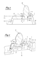
- the figures 4 and 5 represent, in section and slightly in perspective, respectively the insertion of a staple 20 in the support 1 and the staple 20 in place in the support 1.
- the clip 20 must be presented in the positioning zone 9 in an inclined position so that the staple foot 21 can be engaged between the edge of the support wall 2 and the edge of the free end 8 of the tongue 6.
- the operator presses on the staple 20 in order to exert a force on the tongue 6 and so that it collapses to let the staple 20 pass.
- 20 is in place in the buttonhole 3 of the support 1, the tongue 6 takes its place and makes it impossible for the staple to come out of the buttonhole by itself and that the staple 20 is disassembled inadvertently.
- to disassemble the clip 20 that is to say to release the clip from the buttonhole 3, it is necessary first to press the tongue 6 so that it bends towards the plane P2 and thus leaves the door open. staple 20.
- the figures 4 and 5 confirm, moreover, what is less visible on the figure 1 that is, the clip holder 1 has no bottom.
- the staple support 1 rises above an opening 18 formed in the element 30.
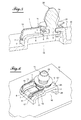
- the figures 6 and 7 represent a variant of the first embodiment of the invention and a staple 20 placed in the staple holder which bears here reference 101.
- the staple support 101 is a part made separately of an element 31 on which the clip 20 must be fixed, but with the same structure as the support
- the staple holder 101 is fixed to the member 31, for example by clipping.
- the element 31 is provided, at each location provided for a staple holder 101, perforations 32, usually in quantities three or four, and the staple holder 101 is provided with the same amount of claws 33 intended to be engaged in the corresponding perforations 32 of the element 31.
- the staple support can be attached to the element on which the staple is to be mounted, by welding or gluing.
- the figure 8 represents a second embodiment of the invention and a staple 20 placed in the staple holder which is here reference 201.
- the staple holder 201 has the same functional structure as the staple holder 1. However , the staple holder 201 differs from the staple holder 1 by making the fourth of the four sides which carry the support wall 2, in the form of a closed right side wall 216.
- the staple holder 201 made of material with the element that must be equipped, looks, because of the inclined side and rear walls, to a truncated pyramid. It can be demolded without demolding assistance, especially without demolding mechanism, with the element 30 which is equipped.
Abstract
L'invention porte sur un support (1) pour une agrafe comprenant un pied d'agrafe et une portion d'attache à une structure, le support (1) comportant une paroi d'appui (2) sur laquelle la portion d'attache de l'agrafe repose après insertion de l'agrafe dans le support et en dessous de laquelle paroi d'appui (2) le pied d'agrafe vient se loger par l'insertion de l'agrafe dans le support (1), la paroi d'appui (2) étant pourvue à cet effet d'une boutonnière (3) ouverte à une (5) de ses deux extrémités opposées (4, 5). Le support (1) comprend en outre une languette (6) solidaire du support (1) par une (7) de ses deux extrémités opposées (7, 8), l'autre extrémité (8) étant libre et orientée vers l'extrémité ouverte (5) de la boutonnière (3) de façon à pouvoir empêcher l'agrafe (1) de sortir d'elle-même de la boutonnière (3).The invention relates to a support (1) for a staple comprising a staple foot and a fastening portion to a structure, the support (1) comprising a support wall (2) on which the attachment portion the staple rests after insertion of the staple into the support and below which the support wall (2) the staple foot is housed by the insertion of the staple in the support (1), the bearing wall (2) being provided for this purpose with a buttonhole (3) open at one (5) of its two opposite ends (4, 5). The support (1) further comprises a tongue (6) secured to the support (1) by one (7) of its two opposite ends (7, 8), the other end (8) being free and facing towards the end open (5) of the buttonhole (3) so as to prevent the staple (1) from coming out of itself from the buttonhole (3).
L'invention porte également sur un procédé d'insertion d'une agrafe dans un tel support d'agrafe (1).

Description
L'invention concerne un support d'agrafe pour une agrafe comprenant un pied d'agrafe et une portion d'attache à une structure ainsi qu'un procédé d'insertion d'une agrafe comprenant un pied d'agrafe et une portion d'attache à une structure, dans un tel support d'agrafe.A staple carrier for a staple comprising a staple foot and a fastening portion to a structure and a method of inserting a staple comprising a staple foot and a staple portion. attaches to a structure, in such a clip holder.
Pour faciliter à la fois le montage et le démontage de panneaux d'habillage et d'autres éléments amovibles dans un véhicule automobile, ces éléments sont pourvus d'agrafes formées pour être engagées dans des orifices aménagés à cet effet dans la structure qui doit recevoir l'élément.To facilitate both the assembly and disassembly of trim panels and other removable elements in a motor vehicle, these elements are provided with staples formed to be engaged in orifices arranged for this purpose in the structure to receive item.
Cependant, dans la plupart des cas, le montage des agrafes sur l'élément à attacher à une structure s'effectue en force à travers une boutonnière dont le passage est rétréci localement pour éviter que les agrafes ne puissent sortir d'elles-mêmes de leur logement. La boutonnière peut faire partie d'un support rapporté à l'élément à attacher tout comme la boutonnière peut être intégrée dans l'élément. Dans les deux cas, la force nécessaire pour ce type de montage dépasse nettement les efforts admis pour un montage manuel ; ce travail est donc réalisé avec des outils automatiques.However, in most cases, the mounting of the staples on the element to be attached to a structure is made forcefully through a buttonhole whose passage is narrowed locally to prevent the staples can go out of their own accord. their housing. The buttonhole can be part of a support attached to the element to be fastened just as the buttonhole can be integrated into the element. In both cases, the force required for this type of mounting clearly exceeds the forces allowed for manual mounting; this work is done with automatic tools.
Toutefois, dans certains cas, le montage des agrafes doit être effectué exclusivement manuellement.However, in some cases, the mounting of the staples must be performed exclusively manually.
Le but de l'invention est en conséquence de proposer un support d'agrafe formé de façon à ce que l'effort d'introduction de l'agrafe dans le support reste inférieur à 2 daN qui est le seuil de pénibilité acceptable pour ce type d'opération.The object of the invention is therefore to provide a staple support formed so that the insertion force of the staple in the support remains less than 2 daN which is the acceptable threshold of hardness for this type. operation.
Le but de l'invention est atteint avec un support pour une agrafe comprenant un pied d'agrafe et une portion d'attache à une structure, le support comportant une paroi d'appui sur laquelle la portion d'attache de l'agrafe repose après insertion de l'agrafe dans le support et en dessous de laquelle paroi d'appui le pied d'agrafe vient se loger par l'insertion de l'agrafe dans le support, la paroi d'appui étant pourvue à cet effet d'une boutonnière ouverte à une de ses deux extrémités opposées et le support comprenant en outre une languette solidaire du support par une de ses deux extrémités opposées, l'autre extrémité étant libre et orientée vers l'extrémité ouverte de la boutonnière de façon à pouvoir empêcher l'agrafe de sortir d'elle-même de la boutonnière.The object of the invention is achieved with a support for a staple comprising a staple foot and a fastening portion to a structure, the support comprising a support wall on which the attachment portion of the staple rests. after insertion of the staple into the support and below which the support wall the staple foot is housed by the insertion of the staple in the support, the support wall being provided for this purpose of a buttonhole open at one of its two opposite ends and the support further comprising a tab secured to the support by one of its two opposite ends, the other end being free and oriented towards the open end of the buttonhole so as to prevent the staple to come out of the buttonhole by itself.
Selon le mode de réalisation choisi, l'invention concerne également au moins une des caractéristiques supplémentaires suivantes, considérées isolément ou en combinaison :
- le support d'agrafe comprend une zone de positionnement servant à positionner l'agrafe avant son introduction dans la boutonnière, la zone de positionnement étant bordée par deux nervures de centrage ;
- la languette est un élément flexible permettant, sous l'effort de montage exercé sur l'agrafe, le passage de l'agrafe dans la boutonnière ;
- la languette est disposée dans la zone de positionnement pour l'agrafe ;
- la languette est située à un niveau inférieur par rapport au niveau de la paroi d'appui.
- the staple holder comprises a positioning area for positioning the staple prior to insertion into the buttonhole, the positioning area being bordered by two centering ribs;
- the tongue is a flexible element allowing, under the mounting force exerted on the staple, the passage of the staple in the buttonhole;
- the tongue is disposed in the positioning zone for the staple;
- the tongue is located at a lower level relative to the level of the support wall.
Le but de l'invention est également atteint avec un procédé d'insertion d'une agrafe comprenant un pied d'agrafe et une portion d'attache à une structure, dans un support d'agrafe comportant une paroi d'appui sur laquelle la portion d'attache de l'agrafe repose après insertion de l'agrafe dans le support d'agrafe et en dessous de laquelle paroi d'appui le pied d'agrafe vient se loger par l'insertion de l'agrafe dans le support, la paroi d'appui étant pourvue à cet effet d'une boutonnière ouverte à une de ses deux extrémités opposées et le support d'agrafe comportant en outre une languette flexible et solidaire du support par une de ses deux extrémités opposées, l'autre extrémité étant libre et orientée vers l'extrémité ouverte de la boutonnière de façon à pouvoir empêcher l'agrafe de sortir d'elle-même de la boutonnière, le procédé comprenant les étapes de présentation de l'agrafe devant l'extrémité ouverte de la boutonnière dans une position inclinée permettant d'introduire le pied d'agrafe entre la languette et l'extrémité ouverte de la boutonnière et insertion de l'agrafe dans le support d'agrafe avec appui concomitant de l'agrafe sur la languette pour la faire s'affaisser le temps que l'agrafe passe.The object of the invention is also achieved with a method of inserting a staple comprising a staple foot and a fastening portion to a structure, in a staple carrier having a bearing wall on which the attachment portion of the staple rests after insertion of the staple into the staple holder and below which the staple foot abuts the staple leg by inserting the staple into the staple, the support wall being provided for this purpose with an open buttonhole at one of its two opposite ends and the staple support further comprising a flexible tongue and secured to the support by one of its two opposite ends, the other end; being free and oriented toward the open end of the buttonhole so as to prevent the staple from coming out of the buttonhole by itself, the method comprising the steps of presenting the staple in front of the open end of the buttonhole in an inclined position for introducing the staple foot between the tongue and the open end of the buttonhole and inserting the staple into the staple holder with concomitant support of the staple on the tongue to make it sag time that the clip passes.
L'effort d'introduction de l'agrafe dans le support ne doit pas dépasser 2 daN.The insertion force of the staple in the support must not exceed 2 daN.
D'autres caractéristiques, détails et avantages de la présente invention apparaîtront dans la description ci-après faite en référence aux dessins annexés qui sont donnés uniquement à titre d'exemple illustrant deux modes de réalisation de l'invention et dont :
- la figure 1
- représente, en une vue en perspective, un support d'agrafe selon un premier mode de réalisation de l'invention et une agrafe mise en place dans le support d'agrafe,
- la figure 2
- représente, en une vue en perspective différente, uniquement le support d'agrafe de la
figure 1 , - la figure 3
- représente l'ensemble support d'agrafe et agrafe de la
figure 1 en une vue en coupe longitudinale, - la figure 4
- représente, en une vue mixte en perspective et en coupe longitudinale, l'agrafe en cours d'insertion dans le support d'agrafe de la
figure 1 , - la figure 5
- représente, en la même vue mixte que le
figure 3 , l'agrafe à la fin de son insertion dans le support d'agrafe, - la figure 6
- représente, en une vue en perspective, une variante du premier mode de réalisation de l'invention,
- la figure 7
- représente la variante de réalisation de la
figure 6 en coupe longitudinale, et - la figure 8
- représente, en une vue en perspective, un support d'agrafe selon un second mode de réalisation de l'invention et une agrafe mise en place dans le support d'agrafe.
- Figure 1
- is a perspective view of a staple carrier according to a first embodiment of the invention and a staple in place in the staple carrier,
- Figure 2
- represents, in a different perspective view, only the staple carrier of the
figure 1 , - Figure 3
- represents the clip holder assembly and clip of the
figure 1 in a longitudinal sectional view, - Figure 4
- represents, in a mixed view in perspective and in longitudinal section, the staple being inserted into the staple holder of the
figure 1 , - Figure 5
- represents, in the same mixed view as the
figure 3 , the staple at the end of its insertion into the staple holder, - Figure 6
- represents, in a perspective view, a variant of the first embodiment of the invention,
- Figure 7
- represents the variant embodiment of the
figure 6 in longitudinal section, and - Figure 8
- is a perspective view of a staple holder according to a second embodiment of the invention and a staple in place in the staple holder.
Le support d'agrafe de la présente invention est adapté à des agrafes 20 ayant un pied d'agrafe 21 et une portion d'attache 22 qui est destinée à être engagée dans un orifice aménagé à cet effet dans la structure, par exemple une porte d'un véhicule automobile, qui doit recevoir un élément 30 ou 31 sur lequel est montée l'agrafe 20, par exemple un panneau d'habillage de la face intérieure de cette porte.The staple holder of the present invention is adapted to
Selon un premier mode de réalisation de l'invention, le support d'agrafe est formé par injection et de matière avec l'élément sur lequel l'agrafe doit être montée, l'élément étant référencé en 30. Le dispositif d'injection doit être pourvu d'un mécanisme de démoulage, comme cela est indiqué plus loin. Selon une variante de réalisation, le support d'agrafe est une pièce formée séparément par injection et rapportée à l'élément sur lequel l'agrafe doit être montée, l'élément étant alors référencé en 31. Et selon un second mode de réalisation, le support d'agrafe est formé par injection et de matière avec l'élément sur lequel l'agrafe doit être montée, mais il est formé de façon à pouvoir être obtenu par un démoulage naturel, l'élément étant référencé en 30. La différence entre les deux modes de réalisation et la variante de réalisation portant sur des détails et non pas sur la structure proprement dite du support d'agrafe de l'invention, ce dernier est décrit ci-après en référence au premier mode de réalisation, la description de la variante de réalisation et du second mode de réalisation se limitant à la description des différences par rapport au premier mode de réalisation. Des indications d'orientation (par exemple : arrière, latérale, gauche, supérieure, amont) dans la présente description se réfèrent à la direction d'insertion de l'agrafe dans le support d'agrafe et à la position du support d'agrafe dans les dessins.According to a first embodiment of the invention, the staple support is formed by injection and material with the element on which the staple is to be mounted, the element being referenced at 30. The injection device must be equipped with a demolding mechanism, as indicated below. According to an alternative embodiment, the staple support is a part formed separately by injection and attached to the element on which the staple is to be mounted, the element then being referenced at 31. And according to a second embodiment In one embodiment, the staple carrier is formed by injection and material with the element on which the staple is to be mounted, but is formed so that it can be obtained by natural demolding, the element being referenced at 30. The difference between the two embodiments and the variant of embodiment relating to details and not to the actual structure of the staple support of the invention, the latter is described below with reference to the first embodiment. , the description of the variant embodiment and the second embodiment being limited to the description of the differences with respect to the first embodiment. Orientation indications (for example: rear, side, left, top, upstream) in the present description refer to the insertion direction of the staple in the staple holder and the position of the staple holder. in the drawings.
Un support d'agrafe 1 selon l'invention, représenté sur les
La paroi d'appui 2 est rehaussée par rapport à l'élément 30 et reliée à celui-ci par des étagements 12, 13, une paroi latérale gauche 14 et une paroi arrière 15. Du côté droit, le support d'agrafe 1 est dépourvu de paroi latérale et présente ainsi une ouverture 16 qui sert au moment du démoulage de l'élément 30 sur lequel le, ou généralement plusieurs supports d'agrafe 1 sont formés, au passage d'un mécanisme de démoulage.The bearing
Le support 1 comprend en outre une languette 6 avec une extrémité 7 par laquelle elle est solidaire du support 1 et une extrémité opposée libre 8 orientée vers l'extrémité ouverte 5 de la boutonnière 3 de façon à pouvoir empêcher l'agrafe 1 de sortir d'elle-même de la boutonnière 3. Ainsi, la fonction de la zone de rétrécissement d'une boutonnière traditionnelle est remplie, selon la présente invention, par l'agencement de la languette 6 située en amont de la boutonnière.The
Afin de faciliter l'introduction de l'agrafe 20 dans le support 1, ce dernier comprend une zone de positionnement 9 formée devant l'extrémité ouverte 5 de la boutonnière 3. La zone de positionnement 9 est délimitée latéralement par deux parois de centrage 10, 11 s'étendant perpendiculairement vers le bas par rapport à un premier plan P1 dans lequel s'étend la face supérieure 2A de la paroi d'appui 2. Les parois de centrage 10, 11 s'étendent jusqu'à un deuxième plan P2 qui est parallèle au, et transversalement espacé du, premier plan P1 et dans lequel s'étend transversalement, par rapport au sens d'introduction de l'agrafe 20, un rebord 17 du support 1.In order to facilitate the introduction of the staple 20 into the
Le rebord 17 est la partie du support d'agrafe 1 à laquelle la languette 6 est solidaire au support 1 et à partir de laquelle la languette 6 s'étend d'abord en direction du premier plan P1, de préférence perpendiculairement au plan P2, et ensuite le long d'un troisième plan P3 situé entre le premier plan P1 et le deuxième plan P2 et parallèle à, et transversalement espacé de, chacun desdits autres plans. Le plan P3 est celui dans lequel s'étend la partie horizontale de la face supérieure de la languette 6 et qui correspond à un plan dans lequel s'étend la surface inférieure 2B de la paroi d'appui 2. « Correspondre » signifie ici que les deux plans peuvent être identiques tout comme il peut y avoir un léger espacement entre ces deux plans qui dépend de l'épaisseur du pied d'agrafe 21. De même, l'espacement entre le plan P2 et le plan P3 est déterminé en fonction des dimensions (épaisseur et largeur ou diamètre) du pied d'agrafe 21.The
Les
Les
Les
Selon une solution alternative de cette variante de réalisation du premier mode de réalisation de l'invention, le support d'agrafe peut être rapporté à l'élément sur lequel l'agrafe doit être montée, par soudage ou collage.According to an alternative solution of this variant embodiment of the first embodiment of the invention, the staple support can be attached to the element on which the staple is to be mounted, by welding or gluing.
La
Claims (7)
caractérisé en ce que le support (1) comprend en outre une languette (6) solidaire du support (1) par une (7) de ses deux extrémités opposées (7, 8), l'autre extrémité (8) étant libre et orientée vers l'extrémité ouverte (5) de la boutonnière (3) de façon à pouvoir empêcher l'agrafe (1) de sortir d'elle-même de la boutonnière (3).Support (1) for a staple (20) comprising a staple foot (21) and a fastening portion (22) to a structure, the support (1) having a bearing wall (2) on which the portion attachment (22) of the clip (20) rests after insertion of the clip into the support and below which support wall (22) the staple foot (21) is housed by the insertion of the staple (20) in the support (1), the support wall (21) being provided for this purpose with a buttonhole (3) open at one (5) of its two opposite ends (4, 5) ,
characterized in that the support (1) further comprises a tongue (6) secured to the support (1) by one (7) of its two opposite ends (7, 8), the other end (8) being free and oriented towards the open end (5) of the buttonhole (3) so as to prevent the staple (1) from coming out of itself from the buttonhole (3).
caractérisé en ce qu'il comprend les étapes de présentation de l'agrafe (20) devant l'extrémité ouverte (5) de la boutonnière (3) dans une position inclinée permettant d'introduire le pied d'agrafe (21) entre la languette (6) et l'extrémité ouverte (5) de la boutonnière (3) et insertion de l'agrafe (20) dans le support d'agrafe (1) avec appui concomitant de l'agrafe (20) sur la languette (6) pour la faire s'affaisser le temps que l'agrafe (20) passe.A method of inserting a staple (20) comprising a staple foot (21) and a fastening portion (22) to a structure in a staple carrier (1) having a backing wall (2) ) on which the fastening portion (22) of the staple rests after insertion of the staple (20) into the staple holder (1) and below which the support wall (2) the foot of staple (21) is housed by the insertion of the clip (20) in the support (1), the support wall (22) being provided for this purpose with a buttonhole (3) open to a (5) ) of its two opposite ends (4, 5) and the staple support (1) further comprising a tongue (6) flexible and secured to the support by one (7) of its two opposite ends (7, 8), other end (8) being free and oriented towards the open end (5) of the buttonhole (3) so as to prevent the staple from coming out of the buttonhole (3) on its own,
characterized in that it comprises the steps of presenting the staple (20) in front of the open end (5) of the buttonhole (3) in an inclined position for introducing the staple foot (21) between the tongue (6) and the open end (5) of the buttonhole (3) and insertion of the clip (20) into the clip holder (1) with the clip (20) being supported on the tongue ( 6) to collapse the time that the staple (20) passes.
Priority Applications (2)
| Application Number | Priority Date | Filing Date | Title |
|---|---|---|---|
| EP13178751.7A EP2833004B1 (en) | 2013-07-31 | 2013-07-31 | Clip support |
| ES13178751.7T ES2604035T3 (en) | 2013-07-31 | 2013-07-31 | Clip holder |
Applications Claiming Priority (1)
| Application Number | Priority Date | Filing Date | Title |
|---|---|---|---|
| EP13178751.7A EP2833004B1 (en) | 2013-07-31 | 2013-07-31 | Clip support |
Publications (2)
| Publication Number | Publication Date |
|---|---|
| EP2833004A1 true EP2833004A1 (en) | 2015-02-04 |
| EP2833004B1 EP2833004B1 (en) | 2016-08-24 |
Family
ID=48900843
Family Applications (1)
| Application Number | Title | Priority Date | Filing Date |
|---|---|---|---|
| EP13178751.7A Active EP2833004B1 (en) | 2013-07-31 | 2013-07-31 | Clip support |
Country Status (2)
| Country | Link |
|---|---|
| EP (1) | EP2833004B1 (en) |
| ES (1) | ES2604035T3 (en) |
Cited By (4)
| Publication number | Priority date | Publication date | Assignee | Title |
|---|---|---|---|---|
| WO2017030673A1 (en) * | 2015-08-19 | 2017-02-23 | Toyota Boshoku America, Inc. | Retainer to secure fastener of door trim panel |
| CN108454531A (en) * | 2017-02-17 | 2018-08-28 | 丰田纺织株式会社 | fixture mounting base |
| US20190092251A1 (en) * | 2017-09-27 | 2019-03-28 | Toyota Boshoku Kabushiki Kaisha | Clip mounting seat |
| CN109555762A (en) * | 2017-09-27 | 2019-04-02 | 丰田纺织株式会社 | Fixture mounting base |
Citations (2)
| Publication number | Priority date | Publication date | Assignee | Title |
|---|---|---|---|---|
| WO2008016178A1 (en) * | 2006-08-02 | 2008-02-07 | Daiwa Kasei Industry Co., Ltd. | Clip |
| EP2199630A1 (en) * | 2008-12-17 | 2010-06-23 | Eurostyle France | Holding structure for a fastening element |
-
2013
- 2013-07-31 EP EP13178751.7A patent/EP2833004B1/en active Active
- 2013-07-31 ES ES13178751.7T patent/ES2604035T3/en active Active
Patent Citations (2)
| Publication number | Priority date | Publication date | Assignee | Title |
|---|---|---|---|---|
| WO2008016178A1 (en) * | 2006-08-02 | 2008-02-07 | Daiwa Kasei Industry Co., Ltd. | Clip |
| EP2199630A1 (en) * | 2008-12-17 | 2010-06-23 | Eurostyle France | Holding structure for a fastening element |
Cited By (6)
| Publication number | Priority date | Publication date | Assignee | Title |
|---|---|---|---|---|
| WO2017030673A1 (en) * | 2015-08-19 | 2017-02-23 | Toyota Boshoku America, Inc. | Retainer to secure fastener of door trim panel |
| US10017130B2 (en) | 2015-08-19 | 2018-07-10 | Toyota Boshoku America, Inc. | Retainer to secure fastener of door trim panel |
| CN108454531A (en) * | 2017-02-17 | 2018-08-28 | 丰田纺织株式会社 | fixture mounting base |
| US20190092251A1 (en) * | 2017-09-27 | 2019-03-28 | Toyota Boshoku Kabushiki Kaisha | Clip mounting seat |
| CN109555762A (en) * | 2017-09-27 | 2019-04-02 | 丰田纺织株式会社 | Fixture mounting base |
| US10717398B2 (en) | 2017-09-27 | 2020-07-21 | Toyota Boshoku Kabushiki Kaisha | Clip mounting seat |
Also Published As
| Publication number | Publication date |
|---|---|
| ES2604035T3 (en) | 2017-03-02 |
| EP2833004B1 (en) | 2016-08-24 |
Similar Documents
| Publication | Publication Date | Title |
|---|---|---|
| EP2833004B1 (en) | Clip support | |
| EP1859173A1 (en) | Fixing rivet | |
| FR2889268A1 (en) | Temporary fixing unit for fixing trim on vehicle door panel, has male part with deformable end portion in one component, where one of lug portions of end portion forms angle with respect to intermediate portion of male part | |
| EP2445748B1 (en) | Device for rigidly connecting a seat portion to a vehicle floor | |
| FR2857314A1 (en) | Bumpers lateral parts fixation device for motor vehicle, has lateral plate supporting and removably locking corresponding lateral part between support plate and flange of fender | |
| FR2866758A1 (en) | Metallic frame for supporting e.g. switch, has two frame sides with windows having one of its portion pierced on upper side and another portion on edge of frame, where each window receives driving screw with head screwed in clamping jaw | |
| FR3040649A1 (en) | DEVICE FOR PRE-MAINTAINING AN ELEMENT AND ITS SCREWS BEFORE SCREWING ON AN EQUIPMENT | |
| EP1784342B1 (en) | Device for conditioning fixing elements | |
| FR2769567A1 (en) | DEVICE FOR FIXING A FRONT PANEL TO THE FRONT STRUCTURE OF A MOTOR VEHICLE | |
| EP0169747B1 (en) | Bumpers for a vehicle | |
| FR3122620A1 (en) | REAR SHELF OF A MOTOR VEHICLE PROVIDED WITH A STORAGE TRAY | |
| EP1258389B1 (en) | Closure device for an opening in a wall for fastening an object, such as an automotive vehicle seat | |
| EP3849845A1 (en) | Device for attaching a trim to a motor vehicle bodywork structure such as a window post | |
| FR2900681A1 (en) | Frame rod and bolt connector for lock of e.g. door leaf, has housing delimited by lateral walls and receiving frame rod`s end including hooking unit e.g. cavity, complementary to hooking unit e.g. projecting part, of housing | |
| EP3248848B1 (en) | Securing device for fitting a windscreen wiper on a drive arm, and corresponding wiping system | |
| EP4012122B1 (en) | Rainwater collector for installation on a downpipe, comprising a removable bailer | |
| FR2878810A1 (en) | Mud-flap fixing bar for motor vehicle, has sectile part separated from bar to receive mud-flap`s clamping bolt arranged in zone distinct from zone of bar, where part has nut shape allowing it to rotatably fix with appropriate tool | |
| FR2919247A3 (en) | Safety belt buckle's clasp fixing device for seat structure of motor vehicle, has fixation body formed from part engaged in buckle of strap and from keying part inserted in opening formed in seat structure | |
| FR2536128A1 (en) | Elastic clip for fixing a panel to a support | |
| FR2871943A1 (en) | Case e.g. battery, positioning and fixing device for motor vehicle, has stop portion connecting lower and upper support portions at side opposite to wall and limiting movement of battery, where upper portion has lug contacting with wall | |
| FR2818620A1 (en) | Support for assembly of vehicle trim components having same decorative finish comprises plastic or metal tray with raised sections for components | |
| FR2599319A1 (en) | Device for protecting the driver of a vehicle against attack by passengers | |
| FR2884852A1 (en) | Rolling shutter, has slides with chamber for housing foot, and rolling shaft with ends supported by bearing and support formed from metal bar, where bar is foldable in two directions such that bends separate foot and upper part of support | |
| FR2994232A1 (en) | ELASTIC ATTACHMENT, ATTACHMENT DEVICE AND METHOD FOR MANUFACTURING THE SAME | |
| FR2832361A1 (en) | Seat for motor vehicle has squab mounted to fixing plate with frangible lock to engage lug on vehicle bodywork |
Legal Events
| Date | Code | Title | Description |
|---|---|---|---|
| 17P | Request for examination filed |
Effective date: 20130731 |
|
| AK | Designated contracting states |
Kind code of ref document: A1 Designated state(s): AL AT BE BG CH CY CZ DE DK EE ES FI FR GB GR HR HU IE IS IT LI LT LU LV MC MK MT NL NO PL PT RO RS SE SI SK SM TR |
|
| AX | Request for extension of the european patent |
Extension state: BA ME |
|
| PUAI | Public reference made under article 153(3) epc to a published international application that has entered the european phase |
Free format text: ORIGINAL CODE: 0009012 |
|
| R17P | Request for examination filed (corrected) |
Effective date: 20150210 |
|
| RBV | Designated contracting states (corrected) |
Designated state(s): AL AT BE BG CH CY CZ DE DK EE ES FI FR GB GR HR HU IE IS IT LI LT LU LV MC MK MT NL NO PL PT RO RS SE SI SK SM TR |
|
| 17Q | First examination report despatched |
Effective date: 20151027 |
|
| GRAP | Despatch of communication of intention to grant a patent |
Free format text: ORIGINAL CODE: EPIDOSNIGR1 |
|
| INTG | Intention to grant announced |
Effective date: 20160301 |
|
| GRAS | Grant fee paid |
Free format text: ORIGINAL CODE: EPIDOSNIGR3 |
|
| GRAA | (expected) grant |
Free format text: ORIGINAL CODE: 0009210 |
|
| AK | Designated contracting states |
Kind code of ref document: B1 Designated state(s): AL AT BE BG CH CY CZ DE DK EE ES FI FR GB GR HR HU IE IS IT LI LT LU LV MC MK MT NL NO PL PT RO RS SE SI SK SM TR |
|
| REG | Reference to a national code |
Ref country code: GB Ref legal event code: FG4D Free format text: NOT ENGLISH |
|
| REG | Reference to a national code |
Ref country code: CH Ref legal event code: EP |
|
| REG | Reference to a national code |
Ref country code: AT Ref legal event code: REF Ref document number: 823382 Country of ref document: AT Kind code of ref document: T Effective date: 20160915 |
|
| REG | Reference to a national code |
Ref country code: IE Ref legal event code: FG4D Free format text: LANGUAGE OF EP DOCUMENT: FRENCH |
|
| REG | Reference to a national code |
Ref country code: DE Ref legal event code: R096 Ref document number: 602013010545 Country of ref document: DE |
|
| REG | Reference to a national code |
Ref country code: RO Ref legal event code: EPE |
|
| REG | Reference to a national code |
Ref country code: LT Ref legal event code: MG4D |
|
| REG | Reference to a national code |
Ref country code: NL Ref legal event code: MP Effective date: 20160824 |
|
| PG25 | Lapsed in a contracting state [announced via postgrant information from national office to epo] |
Ref country code: LT Free format text: LAPSE BECAUSE OF FAILURE TO SUBMIT A TRANSLATION OF THE DESCRIPTION OR TO PAY THE FEE WITHIN THE PRESCRIBED TIME-LIMIT Effective date: 20160824 Ref country code: RS Free format text: LAPSE BECAUSE OF FAILURE TO SUBMIT A TRANSLATION OF THE DESCRIPTION OR TO PAY THE FEE WITHIN THE PRESCRIBED TIME-LIMIT Effective date: 20160824 Ref country code: HR Free format text: LAPSE BECAUSE OF FAILURE TO SUBMIT A TRANSLATION OF THE DESCRIPTION OR TO PAY THE FEE WITHIN THE PRESCRIBED TIME-LIMIT Effective date: 20160824 Ref country code: NL Free format text: LAPSE BECAUSE OF FAILURE TO SUBMIT A TRANSLATION OF THE DESCRIPTION OR TO PAY THE FEE WITHIN THE PRESCRIBED TIME-LIMIT Effective date: 20160824 Ref country code: NO Free format text: LAPSE BECAUSE OF FAILURE TO SUBMIT A TRANSLATION OF THE DESCRIPTION OR TO PAY THE FEE WITHIN THE PRESCRIBED TIME-LIMIT Effective date: 20161124 Ref country code: FI Free format text: LAPSE BECAUSE OF FAILURE TO SUBMIT A TRANSLATION OF THE DESCRIPTION OR TO PAY THE FEE WITHIN THE PRESCRIBED TIME-LIMIT Effective date: 20160824 |
|
| PG25 | Lapsed in a contracting state [announced via postgrant information from national office to epo] |
Ref country code: PT Free format text: LAPSE BECAUSE OF FAILURE TO SUBMIT A TRANSLATION OF THE DESCRIPTION OR TO PAY THE FEE WITHIN THE PRESCRIBED TIME-LIMIT Effective date: 20161226 Ref country code: SE Free format text: LAPSE BECAUSE OF FAILURE TO SUBMIT A TRANSLATION OF THE DESCRIPTION OR TO PAY THE FEE WITHIN THE PRESCRIBED TIME-LIMIT Effective date: 20160824 Ref country code: GR Free format text: LAPSE BECAUSE OF FAILURE TO SUBMIT A TRANSLATION OF THE DESCRIPTION OR TO PAY THE FEE WITHIN THE PRESCRIBED TIME-LIMIT Effective date: 20161125 Ref country code: LV Free format text: LAPSE BECAUSE OF FAILURE TO SUBMIT A TRANSLATION OF THE DESCRIPTION OR TO PAY THE FEE WITHIN THE PRESCRIBED TIME-LIMIT Effective date: 20160824 |
|
| PG25 | Lapsed in a contracting state [announced via postgrant information from national office to epo] |
Ref country code: EE Free format text: LAPSE BECAUSE OF FAILURE TO SUBMIT A TRANSLATION OF THE DESCRIPTION OR TO PAY THE FEE WITHIN THE PRESCRIBED TIME-LIMIT Effective date: 20160824 |
|
| REG | Reference to a national code |
Ref country code: SK Ref legal event code: T3 Ref document number: E 22670 Country of ref document: SK |
|
| REG | Reference to a national code |
Ref country code: DE Ref legal event code: R097 Ref document number: 602013010545 Country of ref document: DE |
|
| PG25 | Lapsed in a contracting state [announced via postgrant information from national office to epo] |
Ref country code: BG Free format text: LAPSE BECAUSE OF FAILURE TO SUBMIT A TRANSLATION OF THE DESCRIPTION OR TO PAY THE FEE WITHIN THE PRESCRIBED TIME-LIMIT Effective date: 20161124 Ref country code: PL Free format text: LAPSE BECAUSE OF FAILURE TO SUBMIT A TRANSLATION OF THE DESCRIPTION OR TO PAY THE FEE WITHIN THE PRESCRIBED TIME-LIMIT Effective date: 20160824 Ref country code: SM Free format text: LAPSE BECAUSE OF FAILURE TO SUBMIT A TRANSLATION OF THE DESCRIPTION OR TO PAY THE FEE WITHIN THE PRESCRIBED TIME-LIMIT Effective date: 20160824 Ref country code: DK Free format text: LAPSE BECAUSE OF FAILURE TO SUBMIT A TRANSLATION OF THE DESCRIPTION OR TO PAY THE FEE WITHIN THE PRESCRIBED TIME-LIMIT Effective date: 20160824 |
|
| PLBE | No opposition filed within time limit |
Free format text: ORIGINAL CODE: 0009261 |
|
| STAA | Information on the status of an ep patent application or granted ep patent |
Free format text: STATUS: NO OPPOSITION FILED WITHIN TIME LIMIT |
|
| REG | Reference to a national code |
Ref country code: FR Ref legal event code: PLFP Year of fee payment: 5 |
|
| 26N | No opposition filed |
Effective date: 20170526 |
|
| PG25 | Lapsed in a contracting state [announced via postgrant information from national office to epo] |
Ref country code: SI Free format text: LAPSE BECAUSE OF FAILURE TO SUBMIT A TRANSLATION OF THE DESCRIPTION OR TO PAY THE FEE WITHIN THE PRESCRIBED TIME-LIMIT Effective date: 20160824 |
|
| REG | Reference to a national code |
Ref country code: CH Ref legal event code: PL |
|
| GBPC | Gb: european patent ceased through non-payment of renewal fee |
Effective date: 20170731 |
|
| PG25 | Lapsed in a contracting state [announced via postgrant information from national office to epo] |
Ref country code: GB Free format text: LAPSE BECAUSE OF NON-PAYMENT OF DUE FEES Effective date: 20170731 Ref country code: CH Free format text: LAPSE BECAUSE OF NON-PAYMENT OF DUE FEES Effective date: 20170731 Ref country code: LI Free format text: LAPSE BECAUSE OF NON-PAYMENT OF DUE FEES Effective date: 20170731 |
|
| REG | Reference to a national code |
Ref country code: IE Ref legal event code: MM4A |
|
| REG | Reference to a national code |
Ref country code: BE Ref legal event code: MM Effective date: 20170731 |
|
| PG25 | Lapsed in a contracting state [announced via postgrant information from national office to epo] |
Ref country code: LU Free format text: LAPSE BECAUSE OF NON-PAYMENT OF DUE FEES Effective date: 20170731 |
|
| REG | Reference to a national code |
Ref country code: FR Ref legal event code: PLFP Year of fee payment: 6 |
|
| PG25 | Lapsed in a contracting state [announced via postgrant information from national office to epo] |
Ref country code: IE Free format text: LAPSE BECAUSE OF NON-PAYMENT OF DUE FEES Effective date: 20170731 |
|
| PG25 | Lapsed in a contracting state [announced via postgrant information from national office to epo] |
Ref country code: BE Free format text: LAPSE BECAUSE OF NON-PAYMENT OF DUE FEES Effective date: 20170731 |
|
| PG25 | Lapsed in a contracting state [announced via postgrant information from national office to epo] |
Ref country code: MT Free format text: LAPSE BECAUSE OF FAILURE TO SUBMIT A TRANSLATION OF THE DESCRIPTION OR TO PAY THE FEE WITHIN THE PRESCRIBED TIME-LIMIT Effective date: 20160824 |
|
| PG25 | Lapsed in a contracting state [announced via postgrant information from national office to epo] |
Ref country code: AL Free format text: LAPSE BECAUSE OF FAILURE TO SUBMIT A TRANSLATION OF THE DESCRIPTION OR TO PAY THE FEE WITHIN THE PRESCRIBED TIME-LIMIT Effective date: 20160824 |
|
| PGFP | Annual fee paid to national office [announced via postgrant information from national office to epo] |
Ref country code: IT Payment date: 20180925 Year of fee payment: 15 Ref country code: RO Payment date: 20180723 Year of fee payment: 6 |
|
| PGFP | Annual fee paid to national office [announced via postgrant information from national office to epo] |
Ref country code: AT Payment date: 20180727 Year of fee payment: 6 Ref country code: SK Payment date: 20180730 Year of fee payment: 6 Ref country code: CZ Payment date: 20180727 Year of fee payment: 6 |
|
| REG | Reference to a national code |
Ref country code: AT Ref legal event code: UEP Ref document number: 823382 Country of ref document: AT Kind code of ref document: T Effective date: 20160824 |
|
| PG25 | Lapsed in a contracting state [announced via postgrant information from national office to epo] |
Ref country code: HU Free format text: LAPSE BECAUSE OF FAILURE TO SUBMIT A TRANSLATION OF THE DESCRIPTION OR TO PAY THE FEE WITHIN THE PRESCRIBED TIME-LIMIT; INVALID AB INITIO Effective date: 20130731 Ref country code: MC Free format text: LAPSE BECAUSE OF FAILURE TO SUBMIT A TRANSLATION OF THE DESCRIPTION OR TO PAY THE FEE WITHIN THE PRESCRIBED TIME-LIMIT Effective date: 20160824 |
|
| PG25 | Lapsed in a contracting state [announced via postgrant information from national office to epo] |
Ref country code: CY Free format text: LAPSE BECAUSE OF FAILURE TO SUBMIT A TRANSLATION OF THE DESCRIPTION OR TO PAY THE FEE WITHIN THE PRESCRIBED TIME-LIMIT Effective date: 20160824 |
|
| PGFP | Annual fee paid to national office [announced via postgrant information from national office to epo] |
Ref country code: ES Payment date: 20190826 Year of fee payment: 7 |
|
| PG25 | Lapsed in a contracting state [announced via postgrant information from national office to epo] |
Ref country code: MK Free format text: LAPSE BECAUSE OF FAILURE TO SUBMIT A TRANSLATION OF THE DESCRIPTION OR TO PAY THE FEE WITHIN THE PRESCRIBED TIME-LIMIT Effective date: 20160824 |
|
| PGFP | Annual fee paid to national office [announced via postgrant information from national office to epo] |
Ref country code: DE Payment date: 20190930 Year of fee payment: 7 |
|
| REG | Reference to a national code |
Ref country code: AT Ref legal event code: MM01 Ref document number: 823382 Country of ref document: AT Kind code of ref document: T Effective date: 20190731 |
|
| PG25 | Lapsed in a contracting state [announced via postgrant information from national office to epo] |
Ref country code: TR Free format text: LAPSE BECAUSE OF FAILURE TO SUBMIT A TRANSLATION OF THE DESCRIPTION OR TO PAY THE FEE WITHIN THE PRESCRIBED TIME-LIMIT Effective date: 20160824 |
|
| REG | Reference to a national code |
Ref country code: SK Ref legal event code: MM4A Ref document number: E 22670 Country of ref document: SK Effective date: 20190731 |
|
| PG25 | Lapsed in a contracting state [announced via postgrant information from national office to epo] |
Ref country code: AT Free format text: LAPSE BECAUSE OF NON-PAYMENT OF DUE FEES Effective date: 20190731 Ref country code: RO Free format text: LAPSE BECAUSE OF NON-PAYMENT OF DUE FEES Effective date: 20190731 |
|
| PG25 | Lapsed in a contracting state [announced via postgrant information from national office to epo] |
Ref country code: CZ Free format text: LAPSE BECAUSE OF NON-PAYMENT OF DUE FEES Effective date: 20190731 Ref country code: SK Free format text: LAPSE BECAUSE OF NON-PAYMENT OF DUE FEES Effective date: 20190731 |
|
| PG25 | Lapsed in a contracting state [announced via postgrant information from national office to epo] |
Ref country code: IS Free format text: LAPSE BECAUSE OF FAILURE TO SUBMIT A TRANSLATION OF THE DESCRIPTION OR TO PAY THE FEE WITHIN THE PRESCRIBED TIME-LIMIT Effective date: 20161224 |
|
| PG25 | Lapsed in a contracting state [announced via postgrant information from national office to epo] |
Ref country code: IT Free format text: LAPSE BECAUSE OF NON-PAYMENT OF DUE FEES Effective date: 20190731 |
|
| REG | Reference to a national code |
Ref country code: DE Ref legal event code: R119 Ref document number: 602013010545 Country of ref document: DE |
|
| PG25 | Lapsed in a contracting state [announced via postgrant information from national office to epo] |
Ref country code: DE Free format text: LAPSE BECAUSE OF NON-PAYMENT OF DUE FEES Effective date: 20210202 |
|
| REG | Reference to a national code |
Ref country code: ES Ref legal event code: FD2A Effective date: 20220103 |
|
| PG25 | Lapsed in a contracting state [announced via postgrant information from national office to epo] |
Ref country code: ES Free format text: LAPSE BECAUSE OF NON-PAYMENT OF DUE FEES Effective date: 20200801 |
|
| P01 | Opt-out of the competence of the unified patent court (upc) registered |
Effective date: 20230517 |
|
| PGFP | Annual fee paid to national office [announced via postgrant information from national office to epo] |
Ref country code: FR Payment date: 20230720 Year of fee payment: 11 |