EP2832998B1 - Pumpvorrichtung - Google Patents
Pumpvorrichtung Download PDFInfo
- Publication number
- EP2832998B1 EP2832998B1 EP13768264.7A EP13768264A EP2832998B1 EP 2832998 B1 EP2832998 B1 EP 2832998B1 EP 13768264 A EP13768264 A EP 13768264A EP 2832998 B1 EP2832998 B1 EP 2832998B1
- Authority
- EP
- European Patent Office
- Prior art keywords
- pump
- piston
- pressurizing
- drive shaft
- vacuum
- Prior art date
- Legal status (The legal status is an assumption and is not a legal conclusion. Google has not performed a legal analysis and makes no representation as to the accuracy of the status listed.)
- Active
Links
Images



Classifications
-
- F—MECHANICAL ENGINEERING; LIGHTING; HEATING; WEAPONS; BLASTING
- F04—POSITIVE - DISPLACEMENT MACHINES FOR LIQUIDS; PUMPS FOR LIQUIDS OR ELASTIC FLUIDS
- F04B—POSITIVE-DISPLACEMENT MACHINES FOR LIQUIDS; PUMPS
- F04B27/00—Multi-cylinder pumps specially adapted for elastic fluids and characterised by number or arrangement of cylinders
- F04B27/005—Multi-cylinder pumps specially adapted for elastic fluids and characterised by number or arrangement of cylinders with two cylinders
-
- F—MECHANICAL ENGINEERING; LIGHTING; HEATING; WEAPONS; BLASTING
- F04—POSITIVE - DISPLACEMENT MACHINES FOR LIQUIDS; PUMPS FOR LIQUIDS OR ELASTIC FLUIDS
- F04B—POSITIVE-DISPLACEMENT MACHINES FOR LIQUIDS; PUMPS
- F04B1/00—Multi-cylinder machines or pumps characterised by number or arrangement of cylinders
- F04B1/02—Multi-cylinder machines or pumps characterised by number or arrangement of cylinders having two cylinders
-
- F—MECHANICAL ENGINEERING; LIGHTING; HEATING; WEAPONS; BLASTING
- F04—POSITIVE - DISPLACEMENT MACHINES FOR LIQUIDS; PUMPS FOR LIQUIDS OR ELASTIC FLUIDS
- F04B—POSITIVE-DISPLACEMENT MACHINES FOR LIQUIDS; PUMPS
- F04B35/00—Piston pumps specially adapted for elastic fluids and characterised by the driving means to their working members, or by combination with, or adaptation to, specific driving engines or motors, not otherwise provided for
- F04B35/04—Piston pumps specially adapted for elastic fluids and characterised by the driving means to their working members, or by combination with, or adaptation to, specific driving engines or motors, not otherwise provided for the means being electric
-
- F—MECHANICAL ENGINEERING; LIGHTING; HEATING; WEAPONS; BLASTING
- F04—POSITIVE - DISPLACEMENT MACHINES FOR LIQUIDS; PUMPS FOR LIQUIDS OR ELASTIC FLUIDS
- F04B—POSITIVE-DISPLACEMENT MACHINES FOR LIQUIDS; PUMPS
- F04B39/00—Component parts, details, or accessories, of pumps or pumping systems specially adapted for elastic fluids, not otherwise provided for in, or of interest apart from, groups F04B25/00 - F04B37/00
- F04B39/0094—Component parts, details, or accessories, of pumps or pumping systems specially adapted for elastic fluids, not otherwise provided for in, or of interest apart from, groups F04B25/00 - F04B37/00 crankshaft
-
- F—MECHANICAL ENGINEERING; LIGHTING; HEATING; WEAPONS; BLASTING
- F04—POSITIVE - DISPLACEMENT MACHINES FOR LIQUIDS; PUMPS FOR LIQUIDS OR ELASTIC FLUIDS
- F04B—POSITIVE-DISPLACEMENT MACHINES FOR LIQUIDS; PUMPS
- F04B41/00—Pumping installations or systems specially adapted for elastic fluids
- F04B41/06—Combinations of two or more pumps
-
- F—MECHANICAL ENGINEERING; LIGHTING; HEATING; WEAPONS; BLASTING
- F04—POSITIVE - DISPLACEMENT MACHINES FOR LIQUIDS; PUMPS FOR LIQUIDS OR ELASTIC FLUIDS
- F04B—POSITIVE-DISPLACEMENT MACHINES FOR LIQUIDS; PUMPS
- F04B2201/00—Pump parameters
- F04B2201/02—Piston parameters
- F04B2201/0201—Position of the piston
- F04B2201/02011—Angular position of a piston rotating around its own axis
-
- F—MECHANICAL ENGINEERING; LIGHTING; HEATING; WEAPONS; BLASTING
- F04—POSITIVE - DISPLACEMENT MACHINES FOR LIQUIDS; PUMPS FOR LIQUIDS OR ELASTIC FLUIDS
- F04B—POSITIVE-DISPLACEMENT MACHINES FOR LIQUIDS; PUMPS
- F04B2201/00—Pump parameters
- F04B2201/08—Cylinder or housing parameters
- F04B2201/0802—Vibration
-
- F—MECHANICAL ENGINEERING; LIGHTING; HEATING; WEAPONS; BLASTING
- F04—POSITIVE - DISPLACEMENT MACHINES FOR LIQUIDS; PUMPS FOR LIQUIDS OR ELASTIC FLUIDS
- F04B—POSITIVE-DISPLACEMENT MACHINES FOR LIQUIDS; PUMPS
- F04B2203/00—Motor parameters
- F04B2203/02—Motor parameters of rotating electric motors
- F04B2203/0201—Current
Definitions
- the present invention relates to a pump device including a vacuum pump and a pressurizing pump.
- An oscillating-piston-type pump as a type of vacuum pump is known as a reciprocating-type pump that alternately performs suction and discharge of air inside a pump chamber by a piston reciprocating within a cylinder, and is widely used as a vacuum pump or a pressurizing pump, for example.
- a complex type of pump device including two pistons for evacuation and for pressurization, which are simultaneously driven by a common motor, is also known.
- a method of driving this type of pump device there are known a method of causing the two pistons to reciprocate in opposite phases and a method of causing the two pistons to reciprocate in the same phase (see, for example, Patent Document 1 below).
- the former method that is, a drive method of causing both the pistons to reciprocate with rotation phases thereof being made different by 180° has an advantage that a dynamic balance of each pump can be successfully maintained and vibrations of the whole of the pump device can be reduced.
- the latter method that is, a drive method of simultaneously moving both the pistons to a top dead center or a bottom dead center can reduce a load fluctuation of a drive source and achieve a stable operation of the pump device.
- Patent Document 1 Japanese Patent Application Laid-open No. Hei 7-310651
- a pump device including a drive motor, a first pump unit for evacuation, and a second pump unit for pressurization.
- the drive motor includes a first drive shaft and a second drive shaft.
- the drive motor is configured to be capable of rotating the first drive shaft and the second drive shaft in synchronization about a first axis.
- the first pump unit includes a first piston that reciprocates in a direction of a second axis orthogonal to the first axis by a rotation of the first drive shaft, and a first pump chamber that has an internal pressure changing in accordance with a reciprocating movement of the first piston.
- the second pump unit includes a second piston that reciprocates in the direction of the second axis by a rotation of the second drive shaft, and a second pump chamber that has an internal pressure changing in accordance with a reciprocating movement of the second piston.
- the second piston has a phase advanced with a rotational phase difference of more than 0° and less than 80° with respect to the first piston.
- the internal pressure of a pump chamber in an oscillating-type piston pump periodically changes by a reciprocating movement of a piston. For example, when the piston moves from a bottom dead center to a top dead center, the volume of the pump chamber decreases and thus the internal pressure transfers to an increasing direction, and when the piston moves from the top dead center to the bottom dead center, the volume of the pump chamber increases and thus the internal pressure transfers to a decreasing direction.
- the internal pressure of the pump chamber changes within a pressure range (negative pressure) equal to or lower than an atmospheric pressure
- the internal pressure of the pump chamber changes within a pressure range (positive pressure) equal to or higher than the atmospheric pressure.
- the following pump device is configured.
- a pump device including a drive motor, a first pump unit for evacuation, and a second pump unit for pressurization.
- the drive motor includes a first drive shaft and a second drive shaft.
- the drive motor is configured to be capable of rotating the first drive shaft and the second drive shaft in synchronization about a first axis.
- the first pump unit includes a first piston that reciprocates in a direction of a second axis orthogonal to the first axis by a rotation of the first drive shaft, and a first pump chamber that has an internal pressure changing in accordance with a reciprocating movement of the first piston.
- the second pump unit includes a second piston that reciprocates in the direction of the second axis by a rotation of the second drive shaft, and a second pump chamber that has an internal pressure changing in accordance with a reciprocating movement of the second piston.
- the second piston has a phase advanced with a rotational phase difference of more than 0° and less than 80° with respect to the first piston.
- the rotational phase difference can be appropriately set in the range of more than 0° and less than 80°. For example, a stable reduction effect of power consumption is obtained in the range of 40° ⁇ 30°, and a further reduction effect of power consumption is obtained in the range of 40° ⁇ 15°. In such a manner, the rotational phase difference is optimized and thus the pump device can be stably operated at low power consumption.
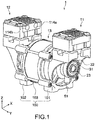
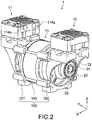
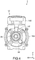
- Figs. 1 to 4 are outer appearance views each showing a pump device according to an embodiment of the present invention.
- Fig. 1 is a perspective view seen from the front side
- Fig. 2 is a perspective view seen from the back side
- Fig. 3 is a right side view
- Fig. 4 is a left side view.
- a pump device 1 of this embodiment includes a vacuum pump unit 11 (first pump unit) as a vacuum stage, a pressurizing pump unit 12 (second pump unit) as a pressurizing stage, and a drive unit 13 that drives in common the vacuum pump unit 11 and the pressurizing pump unit 12.
- the pump device 1 is used as a booster blower of gas used in a fuel cell system or as a vacuum and pressurizing pump used in a medical analyzer.
- the vacuum pump unit 11 and the pressurizing pump unit 12 typically have a common configuration and are each configured as an oscillating piston pump in this embodiment.
- the pump device 1 includes a pump case 100 including a first casing 101 that constitutes a part of the vacuum pump unit 11, a second casing 102 that constitutes a part of the pressurizing pump unit 12, and a third casing 103 that constitutes a part of the drive unit 13.
- Fig. 5 is a vertical cross-sectional view showing a part of a configuration of the vacuum pump unit 11 and the drive unit 13.
- an X axis, a Y axis, and a Z axis represent three axis directions that are orthogonal to one another.
- the pressurizing pump unit 12 has the same configuration as that of the vacuum pump unit 11, and thus the vacuum pump unit 11 will be mainly described here.
- the vacuum pump unit 11 includes the first casing 101, a piston 21, a connecting rod 22 (rod member), and an eccentric member 23.
- the first casing 101 includes a case body 110, a cylinder 111, a pump head 112, and a pump head cover 113.
- the case body 110, the cylinder 111, the pump head 112, and the pump head cover 113 are mutually integrated so as to be stacked in a Z-axis direction.
- the case body 110 is connected to the third casing 103 that contains a motor M, and includes a through-hole 110h through which the connecting rod 22 passes.
- the case body 110 includes a fixing portion 110a that fixes a bearing 32, the bearing 32 rotatably supporting a drive shaft 131 of the motor M, and a cylindrical portion 110b that contains a coil 132 of the motor M.
- the drive shaft 131 is disposed parallel to a Y-axis direction (first axis direction) and rotates about the Y axis by the drive of the motor M.
- the bearing 32 is disposed between the main body of the motor M and the eccentric member 23.
- the cylinder 111 is disposed between the case body 110 and the pump head 112 and contains the piston 21 so as to be slidable in the Z-axis direction.
- the pump head 112 is disposed between the cylinder 111 and the pump head cover 113 and includes a suction valve 112a and a discharge valve 112b.
- the pump head cover 113 is disposed on the pump head 112 and includes a suction chamber 113a that communicates with a suction port 114a and a discharge chamber 113b that communicates with a discharge port 114b.
- the suction port 114a and the discharge port 114b are provided to a side surface of each of the pump units 11 and 12, the side surfaces of the pump units 11 and 12 being opposed to each other as shown in Figs. 1 and 2 .
- the piston 21 has a circular disk shape and is fixed to a first end 221 of the connecting rod 22 via a screw member 25.
- the piston 21 forms a pump chamber 26 between the piston 21 and the pump head 112.
- the piston 21 changes the internal pressure of the pump chamber 26 by a reciprocating movement to a direction parallel to the Z-axis direction (second axis direction) within the cylinder 111.
- the piston 21 alternately performs suction and discharge of air in the pump chamber 26 via the suction valve 112a and the discharge valve 112b, thus performing a predetermined pump action.
- the connecting rod 22 couples the piston 21 and the eccentric member 23 to each other.
- the connecting rod 22 includes the first end 221 connected to the piston 21 and a second end 222 connected to the eccentric member 23.
- the first end 221 is formed into a circular form having substantially the same diameter as the piston 21.
- a circular disk-shaped seal member 24 is attached between the piston 21 and the first end 221. The outer edge of the seal member 24 is folded back to the pump chamber 26 side so as to be capable of sliding on an inner peripheral surface of the cylinder 111.
- a fitting hole 222a into which an eccentric shaft 232 of the eccentric member 23 is fitted is formed in the second end 222 of the connecting rod 22.
- a bearing 31 that rotatably supports the eccentric shaft 232 is fitted to the fitting hole 222a.
- the eccentric member 23 couples the drive shaft 131 of the motor M contained in the third casing 103 and the connecting rod 22 to each other.
- the eccentric member 23 includes a base block 230 having a substantially columnar shape.
- the base block 230 has a surface on the motor M side, to which the drive shaft 131 is coupled, and a surface on the connecting rod 22 side, on which the eccentric shaft 232 is formed.
- the shaft center of the eccentric shaft 232 is eccentric relative to the drive shaft 131 so as to be biased along with the rotation of the drive shaft 131.
- the drive shaft 131 is coupled to the base block 230 with a screw 41 fastened to a side peripheral surface of the base block 230.
- a counterweight 51 is attached to the eccentric member 23.
- the counterweight 51 is fixed to a side peripheral portion of the eccentric member 23 with a fixing screw 42 fastened to the side peripheral surface of the base block 230.
- the counterweight 51 rotates together with the piston 21 and has an action of cancelling a vibration that is generated when the connecting rod 22 rotates about the eccentric shaft 232 along with the rotation of the drive shaft 131.
- the counterweight 51 is disposed at a position biased in a direction opposite to the bias direction of the eccentric shaft 232 with respect to the drive shaft 131.
- the eccentric member 23 rotates about the drive shaft 131 by the drive of the motor M, and thus the eccentric shaft 232 revolves around the drive shaft 131 along a circumference having a radius corresponding to an eccentricity amount from the drive shaft 131.
- the connecting rod 22 coupled to the eccentric shaft 232 converts the rotation of the drive shaft 131 into a reciprocating movement of the piston 21 within the cylinder 111.
- the piston 21 reciprocates in the Z-axis direction while oscillating in the X-axis direction in Fig. 5 within the cylinder 111. With this, the suction and discharge of air in the pump chamber 26 are alternately performed, and a predetermined evacuation action by the vacuum pump unit 11 is obtained.
- the pressurizing pump unit 12 is configured in the same manner as the vacuum pump unit 11, and the drive shaft 131 also protrudes to the pressurizing pump unit 12 side and is coupled to an eccentric shaft (not shown) of the pressurizing pump unit 12. With this, the pressurizing pump unit 12 is driven by the common motor M simultaneously with the vacuum pump unit 11, and a predetermined pressurizing (boosting) action is performed.
- the vacuum pump unit 11 and the pressurizing pump unit 12 are driven in phases that are different from each other.
- the piston 21 (second piston) of the pressurizing pump unit 12 is configured such that its phase is advanced with a rotational phase difference of more than 0° and less than 80° with respect to the piston 21 (first piston) of the vacuum pump unit 11.
- the positions of the eccentric shafts 232 of the respective pumps 11 and 12 are made different. According to this embodiment, since the eccentric members 23 are fixed to the drive shaft 131 by only fastening of the screws 41, it is easy to adjust relative positions of the eccentric shafts 232 of both the pumps 11 and 12.
- a counterweight 52 of the pressurizing pump unit 12 is fixed to a position at which a phase is advanced by the predetermined rotational phase difference (more than 0° and less than 80°) in a rotation direction of the drive shaft 131 (in a clockwise direction about the Y axis in Fig. 3 and in a counterclockwise direction about the Y axis in Fig. 4 ) with respect to the counterweight 51 of the vacuum pump unit 11.
- Fig. 6(A) and (B) is a schematic view for describing a relationship between an eccentric shaft 232v on the vacuum pump unit 11 side and an eccentric shaft 232c on the pressurizing pump unit 12 side, in which (A) is a front view and (B) is a side view seen from the vacuum pump unit 11 side.
- the eccentric shaft 232c on the pressurizing pump side is provided at a position at which a phase is more advanced with a predetermined rotational phase difference ⁇ than the eccentric shaft 232v on the vacuum pump unit 11 side.
- a piston 21v on the vacuum pump unit 11 side and a piston 21c on the pressurizing pump unit 12 side are driven with a shift of a phase difference ⁇ , and the piston 21c arrives at a top dead center earlier than the piston 21v by a time corresponding to the phase difference ⁇ .
- Fig. 7(A) shows results of an experiment showing time changes in internal pressure of the pump chamber and in piston position in the vacuum pump
- Fig. 7(B) shows results of an experiment showing time changes in internal pressure of the pump chamber and in piston position in the pressurizing pump.
- solid lines indicate experimental results of the operation in 50 Hz
- broken lines indicate experimental results of the operation in 60 Hz.
- a lifting height of the pump device used in the experiments was set to 40 [kPa (absolute pressure)] in the vacuum stage (vacuum pump) and set to 220 [kPaG (gauge pressure)] in the pressurizing stage (pressurizing pump).
- the internal pressure of the pump chamber was measured via a tube hermetically inserted into the pump chamber.
- an output of an accelerometer attached to the lower portion of the connecting rod was used.
- a cylinder diameter of the pump in each stage was set to ⁇ 37 mm, the eccentricity amount of the eccentric shaft to 3.3 mm, and the rotation speed of the motor to about 1400 rpm/1700 rpm-range (50Hz/60Hz). The same holds true for the conditions of experimental results shown in Figs. 8 and 9 .
- the internal pressure of the pump chamber is synchronized with the piston position and the internal pressure of the pump chamber and the piston position change in the same phase ( Fig. 7(A) ), while in the pressurizing stage, the internal pressure of the pump chamber is not synchronized with the piston position and a phase difference is caused therebetween ( Fig. 7(B) ). More specifically, before the piston of the pressurizing stage arrives at the top dead center, a pressure peak appears in the pump chamber.
- the pump device is configured such that changes in internal pressure of both the pump chambers have opposite phases in the first pump unit and the second pump unit, it was found by the experiments that power consumption of the drive motor can be reduced as compared to a case where the pistons of the respective pumps are driven in the same phase.
- the fact that time changes in internal pressure have opposite phases typically means that pressure waveforms of the both pump chambers have a phase of 180°, but the present invention is not limited thereto and only needs to have such a phase relationship that can be interpreted to be an opposite phase relationship in a practical sense.
- the opposite phase relationship in the practical sense can be defined as, for example, a phase relationship in which power consumption becomes smaller than in a case where both the pistons are driven in the same phase.
- the piston of the pressurizing stage is set to have a rotational phase difference that is advanced by more than 180° and less than 260° with respect to the piston of the vacuum stage.
- the results of an experiment when the rotational phase difference is 220° are shown in Fig. 7(A) to (C).
- Fig. 7(C) shows a composite waveform of the pressure waveform of the pump chamber in the vacuum stage and the pressure waveform of the pump chamber in the pressurizing stage.
- the piston of the pressurizing stage is set to have a rotational phase difference that is advanced by more than 0° and less than 80° with respect to the piston of the vacuum stage.
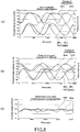
- the results of an experiment when the rotational phase difference is 40° are shown in Fig. 8(A) to (C).
- Fig. 8(A) shows time changes in internal pressure of the pump chamber and in piston position in the vacuum stage.
- FIG. 8(B) shows time changes in internal pressure of the pump chamber and in piston position in the pressurizing stage. Further, Fig. 8(C) shows a composite waveform of the pressure waveform of the pump chamber in the vacuum stage and the pressure waveform of the pump chamber in the pressurizing stage.
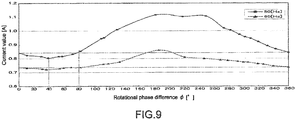
- Fig. 9 shows results of an experiment showing a relationship between a rotational phase difference of the piston of the pressurizing stage with respect to the piston of the vacuum stage and a consumption current of the motor.
- the rotational phase difference in the horizontal axis indicates a phase advance angle of the piston of the pressurizing stage with respect to the piston of the vacuum stage (phase angle by which the piston on the pressurizing side is advanced more than the piston on the vacuum side in the rotation direction of the drive shaft).
- the rotational phase difference ⁇ at the lowest current value is 40°
- the pressure waveforms of the pump chambers in the respective stages at that time have an opposite phase relationship as shown in Fig. 8(A) and (B) .
- a composite waveform of the internal pressures of the pump chambers in the respective stages is as shown in Fig. 8(C) , and the internal pressures of the pump chambers in the respective stages are canceled by each other.
- the consumption current of the motor becomes the minimum.
- the drive current of the motor can be reduced as compared with a case where the rotational phase difference ⁇ is 0° (360°), in the power supply frequency of 50 Hz or 60 Hz.
- the power consumption could be effectively reduced more, and the current value could be reduced by about 4.1% in the case of 50 Hz and by about 2.2% in the case of 60 Hz.
- the phase difference ⁇ is set to 40° ⁇ 15°, and thus it is possible to reduce not only the amount of current consumption but also vibrations generated when the pump device 1 is driven.
- This vibration reducing effect was found in each of the power supply frequencies of 50 Hz and 60 Hz.
- the vacuum pump unit 11 and the pressurizing pump unit 12 that constitute the pump device are each constituted of an oscillating-type piston pump.
- each pump may be constituted of another reciprocating-type piston pump such as a diaphragm pump.
- the pump device including a single drive motor and two pump units has been described as an example, but the present invention is also applicable to a pump device including a plurality of sets (for example, two sets) of pump units each constituted of the drive motor and the two pump units.
Landscapes
- Engineering & Computer Science (AREA)
- Mechanical Engineering (AREA)
- General Engineering & Computer Science (AREA)
- Compressors, Vaccum Pumps And Other Relevant Systems (AREA)
- Details Of Reciprocating Pumps (AREA)
Claims (3)
- Pumpenanordnung, aufweisend:einen Antriebsmotor (M), der eine erste Antriebswelle (131) und eine zweite Antriebswelle (131) umfasst und dazu geeignet ist, die erste Antriebswelle (131) und die zweite Antriebswelle (131) in Synchronisation um eine erste Achse zu drehen;eine erste Pumpeneinheit (11) zum Entleeren, umfassend einen ersten Kolben (21 v), der sich in einer Richtung einer zweiten Achse, die senkrecht zu der ersten Achse ist, um eine Drehung der ersten Antriebswelle (131) vor- und zurückbewegt, und eine erste Pumpenkammer (26), die eine erste interne Druckänderung gemäß einer alternierenden Bewegung des ersten Kolbens (21 v) hat, und eine zweite Pumpeneinheit (12) zur Druckbeaufschlagung, umfassend einen zweiten Kolben (21 c), der sich in der Richtung der zweiten Achse um eine Drehung der zweiten Antriebswelle (131) vor- und zurückbewegt, und eine zweite Pumpenkammer, die eine interne Druckänderung gemäß einer alternierenden Bewegung des zweiten Kolbens (21 c) hat;dadurch gekennzeichnet, dass der zweite Kolben (21 c) eine Phase hat, die mit einer Rotationsphasendifferenz von mehr als 0° und weniger als 80° bezüglich des ersten Kolbens (21 v) vorgerückt ist.
- Pumpenanordnung gemäß Anspruch 1, wobei die Rotationsphasendifferenz gleich 40° +/- 15° ist.
- Pumpenanordnung gemäß Anspruch 1, wobei die erste Pumpeneinheit (11) ferner ein erstes Gegengewicht umfasst, das sich zusammen mit dem ersten Kolben (21 v) um die erste Antriebswelle (131) dreht, und
die zweite Pumpeneinheit (12) ferner ein zweites Gegengewicht aufweist, das sich zusammen mit dem zweiten Kolben (21 c) um die zweite Antriebswelle (131) dreht, mit der Rotationsphasendifferenz in Bezug auf das erste Gegengewicht.
Applications Claiming Priority (2)
| Application Number | Priority Date | Filing Date | Title |
|---|---|---|---|
| JP2012082015 | 2012-03-30 | ||
| PCT/JP2013/001436 WO2013145576A1 (ja) | 2012-03-30 | 2013-03-07 | ポンプ装置 |
Publications (3)
| Publication Number | Publication Date |
|---|---|
| EP2832998A1 EP2832998A1 (de) | 2015-02-04 |
| EP2832998A4 EP2832998A4 (de) | 2016-01-20 |
| EP2832998B1 true EP2832998B1 (de) | 2017-01-18 |
Family
ID=49258896
Family Applications (1)
| Application Number | Title | Priority Date | Filing Date |
|---|---|---|---|
| EP13768264.7A Active EP2832998B1 (de) | 2012-03-30 | 2013-03-07 | Pumpvorrichtung |
Country Status (7)
| Country | Link |
|---|---|
| US (1) | US20150086402A1 (de) |
| EP (1) | EP2832998B1 (de) |
| JP (1) | JP5878625B2 (de) |
| KR (1) | KR101602089B1 (de) |
| CN (1) | CN104204522B (de) |
| TW (1) | TWI619883B (de) |
| WO (1) | WO2013145576A1 (de) |
Families Citing this family (5)
| Publication number | Priority date | Publication date | Assignee | Title |
|---|---|---|---|---|
| US20150147202A1 (en) * | 2013-11-27 | 2015-05-28 | Gardner Denver Thomas, Inc. | Pump having interchangeable heads |
| WO2016037655A1 (de) * | 2014-09-11 | 2016-03-17 | Gaydoul Jürgen | Verdrängereinrichtung |
| CN104612937B (zh) * | 2015-03-06 | 2017-08-04 | 宁波捷美进出口有限公司 | 车用充气泵 |
| CN111255666B (zh) * | 2018-12-03 | 2023-11-28 | 广东美的白色家电技术创新中心有限公司 | 增压泵和净水设备 |
| CN112032022B (zh) * | 2020-09-10 | 2024-04-26 | 北京通嘉宏瑞科技有限公司 | 一种无死角吹扫气体的干式真空泵及其使用方法 |
Family Cites Families (10)
| Publication number | Priority date | Publication date | Assignee | Title |
|---|---|---|---|---|
| US3190233A (en) * | 1963-03-05 | 1965-06-22 | Welch Harold George | Pumps |
| US5564908A (en) * | 1994-02-14 | 1996-10-15 | Phillips Engineering Company | Fluid pump having magnetic drive |
| JP3640412B2 (ja) | 1994-05-17 | 2005-04-20 | 芝浦メカトロニクス株式会社 | 往復動ポンプユニット |
| US5584675A (en) * | 1995-09-15 | 1996-12-17 | Devilbiss Air Power Company | Cylinder sleeve for an air compressor |
| GB2314593B (en) * | 1996-06-28 | 1999-11-10 | Thomas Industries Inc | Two-cylinder air compressor |
| US6126410A (en) * | 1998-02-12 | 2000-10-03 | Gast Manufacturing Corporation | Head cover assembly for reciprocating compressor |
| JP2006063874A (ja) * | 2004-08-26 | 2006-03-09 | Ulvac Kiko Inc | ダイアフラム型真空ポンプ |
| GB2463821B (en) * | 2005-05-17 | 2010-06-09 | Thomas Industries Inc | Pump improvements |
| JP2008190517A (ja) * | 2007-02-05 | 2008-08-21 | Kazumori Otogao | 可搬型空気圧縮装置 |
| US8128382B2 (en) * | 2007-07-11 | 2012-03-06 | Gast Manufacturing, Inc. | Compact dual rocking piston pump with reduced number of parts |
-
2013
- 2013-03-07 JP JP2014507375A patent/JP5878625B2/ja active Active
- 2013-03-07 WO PCT/JP2013/001436 patent/WO2013145576A1/ja not_active Ceased
- 2013-03-07 EP EP13768264.7A patent/EP2832998B1/de active Active
- 2013-03-07 US US14/386,641 patent/US20150086402A1/en not_active Abandoned
- 2013-03-07 KR KR1020147026361A patent/KR101602089B1/ko active Active
- 2013-03-07 CN CN201380017010.XA patent/CN104204522B/zh active Active
- 2013-03-15 TW TW102109327A patent/TWI619883B/zh active
Non-Patent Citations (1)
| Title |
|---|
| None * |
Also Published As
| Publication number | Publication date |
|---|---|
| EP2832998A4 (de) | 2016-01-20 |
| JP5878625B2 (ja) | 2016-03-08 |
| TW201400702A (zh) | 2014-01-01 |
| WO2013145576A1 (ja) | 2013-10-03 |
| JPWO2013145576A1 (ja) | 2015-12-10 |
| US20150086402A1 (en) | 2015-03-26 |
| EP2832998A1 (de) | 2015-02-04 |
| KR20140126757A (ko) | 2014-10-31 |
| TWI619883B (zh) | 2018-04-01 |
| CN104204522B (zh) | 2016-08-24 |
| CN104204522A (zh) | 2014-12-10 |
| KR101602089B1 (ko) | 2016-03-09 |
Similar Documents
| Publication | Publication Date | Title |
|---|---|---|
| EP2832998A1 (de) | Pumpvorrichtung | |
| JP6573605B2 (ja) | 遊星回転機構を有するスピン・ポンプ | |
| EP2613053B1 (de) | Rotationsverdichter mit Dual Exzenterabschnitt | |
| US20140356207A1 (en) | An oil-free scroll fluid machine | |
| CN103807174B (zh) | 一种三缸滚动转子式压缩机 | |
| CN102486174A (zh) | 一种有径向柔性密封的变频涡旋式压缩机 | |
| JP4752241B2 (ja) | 往復動式圧縮機 | |
| CN103216422A (zh) | 压缩机和真空机械 | |
| CN105201844A (zh) | 旋转式压缩机 | |
| KR20120076164A (ko) | 밀폐형 압축기 | |
| CN104963867A (zh) | 旋转压缩机及其曲轴 | |
| CN204729305U (zh) | 旋转压缩机的活塞及具有其的旋转压缩机、多级压缩机 | |
| KR20140102753A (ko) | 펌프 장치 | |
| CN105003526B (zh) | 旋转压缩机及其曲轴 | |
| JP2017534802A (ja) | 駆動源に対して適合可能な伝達装置を有するコンプレッサ | |
| CN205578272U (zh) | 涡旋压缩机的机壳结构 | |
| WO2020089997A1 (ja) | 弁装置、ポンプヘッド及びポンプ装置 | |
| US9518582B2 (en) | Motor spacer, motor spacer applied to variable-speed compressor and compressor | |
| CN104929940A (zh) | 旋转压缩机的活塞及具有其的旋转压缩机、多级压缩机 | |
| CN204082540U (zh) | 倍率线体涡旋式压缩机 | |
| CN206111557U (zh) | 一种具有新型泵浦组件的回转式压缩机 | |
| JP2016094923A (ja) | 圧縮機 | |
| CN201148954Y (zh) | 多活塞式空气压缩机 | |
| JP2019056312A (ja) | スクロール圧縮機 | |
| JP2016118152A (ja) | 往復動型流体機械 |
Legal Events
| Date | Code | Title | Description |
|---|---|---|---|
| PUAI | Public reference made under article 153(3) epc to a published international application that has entered the european phase |
Free format text: ORIGINAL CODE: 0009012 |
|
| 17P | Request for examination filed |
Effective date: 20140916 |
|
| AK | Designated contracting states |
Kind code of ref document: A1 Designated state(s): AL AT BE BG CH CY CZ DE DK EE ES FI FR GB GR HR HU IE IS IT LI LT LU LV MC MK MT NL NO PL PT RO RS SE SI SK SM TR |
|
| AX | Request for extension of the european patent |
Extension state: BA ME |
|
| DAX | Request for extension of the european patent (deleted) | ||
| REG | Reference to a national code |
Ref country code: DE Ref legal event code: R079 Ref document number: 602013016764 Country of ref document: DE Free format text: PREVIOUS MAIN CLASS: F04B0041060000 Ipc: F04B0027000000 |
|
| RA4 | Supplementary search report drawn up and despatched (corrected) |
Effective date: 20151222 |
|
| RIC1 | Information provided on ipc code assigned before grant |
Ipc: F04B 39/00 20060101ALI20151216BHEP Ipc: F04B 35/04 20060101ALI20151216BHEP Ipc: F04B 41/06 20060101ALI20151216BHEP Ipc: F04B 27/00 20060101AFI20151216BHEP |
|
| GRAP | Despatch of communication of intention to grant a patent |
Free format text: ORIGINAL CODE: EPIDOSNIGR1 |
|
| INTG | Intention to grant announced |
Effective date: 20160919 |
|
| RIN1 | Information on inventor provided before grant (corrected) |
Inventor name: TANABE, YUSAKU Inventor name: CHOUNO, MOTOYASU Inventor name: OSAKA, TAISUKE Inventor name: ITOYAMA, RYUJI |
|
| GRAS | Grant fee paid |
Free format text: ORIGINAL CODE: EPIDOSNIGR3 |
|
| GRAA | (expected) grant |
Free format text: ORIGINAL CODE: 0009210 |
|
| AK | Designated contracting states |
Kind code of ref document: B1 Designated state(s): AL AT BE BG CH CY CZ DE DK EE ES FI FR GB GR HR HU IE IS IT LI LT LU LV MC MK MT NL NO PL PT RO RS SE SI SK SM TR |
|
| REG | Reference to a national code |
Ref country code: GB Ref legal event code: FG4D |
|
| REG | Reference to a national code |
Ref country code: CH Ref legal event code: EP |
|
| REG | Reference to a national code |
Ref country code: AT Ref legal event code: REF Ref document number: 863071 Country of ref document: AT Kind code of ref document: T Effective date: 20170215 |
|
| REG | Reference to a national code |
Ref country code: IE Ref legal event code: FG4D |
|
| REG | Reference to a national code |
Ref country code: DE Ref legal event code: R096 Ref document number: 602013016764 Country of ref document: DE |
|
| REG | Reference to a national code |
Ref country code: NL Ref legal event code: MP Effective date: 20170118 |
|
| REG | Reference to a national code |
Ref country code: LT Ref legal event code: MG4D |
|
| REG | Reference to a national code |
Ref country code: AT Ref legal event code: MK05 Ref document number: 863071 Country of ref document: AT Kind code of ref document: T Effective date: 20170118 |
|
| PG25 | Lapsed in a contracting state [announced via postgrant information from national office to epo] |
Ref country code: NL Free format text: LAPSE BECAUSE OF FAILURE TO SUBMIT A TRANSLATION OF THE DESCRIPTION OR TO PAY THE FEE WITHIN THE PRESCRIBED TIME-LIMIT Effective date: 20170118 |
|
| PG25 | Lapsed in a contracting state [announced via postgrant information from national office to epo] |
Ref country code: IS Free format text: LAPSE BECAUSE OF FAILURE TO SUBMIT A TRANSLATION OF THE DESCRIPTION OR TO PAY THE FEE WITHIN THE PRESCRIBED TIME-LIMIT Effective date: 20170518 Ref country code: FI Free format text: LAPSE BECAUSE OF FAILURE TO SUBMIT A TRANSLATION OF THE DESCRIPTION OR TO PAY THE FEE WITHIN THE PRESCRIBED TIME-LIMIT Effective date: 20170118 Ref country code: NO Free format text: LAPSE BECAUSE OF FAILURE TO SUBMIT A TRANSLATION OF THE DESCRIPTION OR TO PAY THE FEE WITHIN THE PRESCRIBED TIME-LIMIT Effective date: 20170418 Ref country code: LT Free format text: LAPSE BECAUSE OF FAILURE TO SUBMIT A TRANSLATION OF THE DESCRIPTION OR TO PAY THE FEE WITHIN THE PRESCRIBED TIME-LIMIT Effective date: 20170118 Ref country code: GR Free format text: LAPSE BECAUSE OF FAILURE TO SUBMIT A TRANSLATION OF THE DESCRIPTION OR TO PAY THE FEE WITHIN THE PRESCRIBED TIME-LIMIT Effective date: 20170419 Ref country code: HR Free format text: LAPSE BECAUSE OF FAILURE TO SUBMIT A TRANSLATION OF THE DESCRIPTION OR TO PAY THE FEE WITHIN THE PRESCRIBED TIME-LIMIT Effective date: 20170118 |
|
| PG25 | Lapsed in a contracting state [announced via postgrant information from national office to epo] |
Ref country code: PT Free format text: LAPSE BECAUSE OF FAILURE TO SUBMIT A TRANSLATION OF THE DESCRIPTION OR TO PAY THE FEE WITHIN THE PRESCRIBED TIME-LIMIT Effective date: 20170518 Ref country code: LV Free format text: LAPSE BECAUSE OF FAILURE TO SUBMIT A TRANSLATION OF THE DESCRIPTION OR TO PAY THE FEE WITHIN THE PRESCRIBED TIME-LIMIT Effective date: 20170118 Ref country code: AT Free format text: LAPSE BECAUSE OF FAILURE TO SUBMIT A TRANSLATION OF THE DESCRIPTION OR TO PAY THE FEE WITHIN THE PRESCRIBED TIME-LIMIT Effective date: 20170118 Ref country code: ES Free format text: LAPSE BECAUSE OF FAILURE TO SUBMIT A TRANSLATION OF THE DESCRIPTION OR TO PAY THE FEE WITHIN THE PRESCRIBED TIME-LIMIT Effective date: 20170118 Ref country code: RS Free format text: LAPSE BECAUSE OF FAILURE TO SUBMIT A TRANSLATION OF THE DESCRIPTION OR TO PAY THE FEE WITHIN THE PRESCRIBED TIME-LIMIT Effective date: 20170118 Ref country code: PL Free format text: LAPSE BECAUSE OF FAILURE TO SUBMIT A TRANSLATION OF THE DESCRIPTION OR TO PAY THE FEE WITHIN THE PRESCRIBED TIME-LIMIT Effective date: 20170118 Ref country code: SE Free format text: LAPSE BECAUSE OF FAILURE TO SUBMIT A TRANSLATION OF THE DESCRIPTION OR TO PAY THE FEE WITHIN THE PRESCRIBED TIME-LIMIT Effective date: 20170118 Ref country code: BG Free format text: LAPSE BECAUSE OF FAILURE TO SUBMIT A TRANSLATION OF THE DESCRIPTION OR TO PAY THE FEE WITHIN THE PRESCRIBED TIME-LIMIT Effective date: 20170418 |
|
| REG | Reference to a national code |
Ref country code: DE Ref legal event code: R097 Ref document number: 602013016764 Country of ref document: DE |
|
| PG25 | Lapsed in a contracting state [announced via postgrant information from national office to epo] |
Ref country code: SK Free format text: LAPSE BECAUSE OF FAILURE TO SUBMIT A TRANSLATION OF THE DESCRIPTION OR TO PAY THE FEE WITHIN THE PRESCRIBED TIME-LIMIT Effective date: 20170118 Ref country code: CZ Free format text: LAPSE BECAUSE OF FAILURE TO SUBMIT A TRANSLATION OF THE DESCRIPTION OR TO PAY THE FEE WITHIN THE PRESCRIBED TIME-LIMIT Effective date: 20170118 Ref country code: EE Free format text: LAPSE BECAUSE OF FAILURE TO SUBMIT A TRANSLATION OF THE DESCRIPTION OR TO PAY THE FEE WITHIN THE PRESCRIBED TIME-LIMIT Effective date: 20170118 Ref country code: RO Free format text: LAPSE BECAUSE OF FAILURE TO SUBMIT A TRANSLATION OF THE DESCRIPTION OR TO PAY THE FEE WITHIN THE PRESCRIBED TIME-LIMIT Effective date: 20170118 |
|
| REG | Reference to a national code |
Ref country code: CH Ref legal event code: PL |
|
| PLBE | No opposition filed within time limit |
Free format text: ORIGINAL CODE: 0009261 |
|
| STAA | Information on the status of an ep patent application or granted ep patent |
Free format text: STATUS: NO OPPOSITION FILED WITHIN TIME LIMIT |
|
| PG25 | Lapsed in a contracting state [announced via postgrant information from national office to epo] |
Ref country code: DK Free format text: LAPSE BECAUSE OF FAILURE TO SUBMIT A TRANSLATION OF THE DESCRIPTION OR TO PAY THE FEE WITHIN THE PRESCRIBED TIME-LIMIT Effective date: 20170118 Ref country code: MC Free format text: LAPSE BECAUSE OF FAILURE TO SUBMIT A TRANSLATION OF THE DESCRIPTION OR TO PAY THE FEE WITHIN THE PRESCRIBED TIME-LIMIT Effective date: 20170118 Ref country code: SM Free format text: LAPSE BECAUSE OF FAILURE TO SUBMIT A TRANSLATION OF THE DESCRIPTION OR TO PAY THE FEE WITHIN THE PRESCRIBED TIME-LIMIT Effective date: 20170118 |
|
| 26N | No opposition filed |
Effective date: 20171019 |
|
| GBPC | Gb: european patent ceased through non-payment of renewal fee |
Effective date: 20170418 |
|
| REG | Reference to a national code |
Ref country code: IE Ref legal event code: MM4A |
|
| REG | Reference to a national code |
Ref country code: FR Ref legal event code: ST Effective date: 20171130 |
|
| PG25 | Lapsed in a contracting state [announced via postgrant information from national office to epo] |
Ref country code: LU Free format text: LAPSE BECAUSE OF NON-PAYMENT OF DUE FEES Effective date: 20170307 Ref country code: FR Free format text: LAPSE BECAUSE OF NON-PAYMENT OF DUE FEES Effective date: 20170331 |
|
| PG25 | Lapsed in a contracting state [announced via postgrant information from national office to epo] |
Ref country code: GB Free format text: LAPSE BECAUSE OF NON-PAYMENT OF DUE FEES Effective date: 20170418 Ref country code: CH Free format text: LAPSE BECAUSE OF NON-PAYMENT OF DUE FEES Effective date: 20170331 Ref country code: LI Free format text: LAPSE BECAUSE OF NON-PAYMENT OF DUE FEES Effective date: 20170331 Ref country code: SI Free format text: LAPSE BECAUSE OF FAILURE TO SUBMIT A TRANSLATION OF THE DESCRIPTION OR TO PAY THE FEE WITHIN THE PRESCRIBED TIME-LIMIT Effective date: 20170118 Ref country code: IE Free format text: LAPSE BECAUSE OF NON-PAYMENT OF DUE FEES Effective date: 20170307 |
|
| REG | Reference to a national code |
Ref country code: BE Ref legal event code: MM Effective date: 20170331 |
|
| PG25 | Lapsed in a contracting state [announced via postgrant information from national office to epo] |
Ref country code: BE Free format text: LAPSE BECAUSE OF NON-PAYMENT OF DUE FEES Effective date: 20170331 |
|
| PG25 | Lapsed in a contracting state [announced via postgrant information from national office to epo] |
Ref country code: MT Free format text: LAPSE BECAUSE OF NON-PAYMENT OF DUE FEES Effective date: 20170307 |
|
| PG25 | Lapsed in a contracting state [announced via postgrant information from national office to epo] |
Ref country code: HU Free format text: LAPSE BECAUSE OF FAILURE TO SUBMIT A TRANSLATION OF THE DESCRIPTION OR TO PAY THE FEE WITHIN THE PRESCRIBED TIME-LIMIT; INVALID AB INITIO Effective date: 20130307 |
|
| PG25 | Lapsed in a contracting state [announced via postgrant information from national office to epo] |
Ref country code: CY Free format text: LAPSE BECAUSE OF FAILURE TO SUBMIT A TRANSLATION OF THE DESCRIPTION OR TO PAY THE FEE WITHIN THE PRESCRIBED TIME-LIMIT Effective date: 20170118 |
|
| PG25 | Lapsed in a contracting state [announced via postgrant information from national office to epo] |
Ref country code: MK Free format text: LAPSE BECAUSE OF FAILURE TO SUBMIT A TRANSLATION OF THE DESCRIPTION OR TO PAY THE FEE WITHIN THE PRESCRIBED TIME-LIMIT Effective date: 20170118 |
|
| PG25 | Lapsed in a contracting state [announced via postgrant information from national office to epo] |
Ref country code: TR Free format text: LAPSE BECAUSE OF FAILURE TO SUBMIT A TRANSLATION OF THE DESCRIPTION OR TO PAY THE FEE WITHIN THE PRESCRIBED TIME-LIMIT Effective date: 20170118 |
|
| PG25 | Lapsed in a contracting state [announced via postgrant information from national office to epo] |
Ref country code: AL Free format text: LAPSE BECAUSE OF FAILURE TO SUBMIT A TRANSLATION OF THE DESCRIPTION OR TO PAY THE FEE WITHIN THE PRESCRIBED TIME-LIMIT Effective date: 20170118 |
|
| PGFP | Annual fee paid to national office [announced via postgrant information from national office to epo] |
Ref country code: DE Payment date: 20260325 Year of fee payment: 14 |
|
| PGFP | Annual fee paid to national office [announced via postgrant information from national office to epo] |
Ref country code: IT Payment date: 20260224 Year of fee payment: 14 |