EP2832961A1 - Exhaust treatment device for diesel engine - Google Patents
Exhaust treatment device for diesel engine Download PDFInfo
- Publication number
- EP2832961A1 EP2832961A1 EP13768358.7A EP13768358A EP2832961A1 EP 2832961 A1 EP2832961 A1 EP 2832961A1 EP 13768358 A EP13768358 A EP 13768358A EP 2832961 A1 EP2832961 A1 EP 2832961A1
- Authority
- EP
- European Patent Office
- Prior art keywords
- exhaust
- corona discharge
- passage
- power supply
- swirling
- Prior art date
- Legal status (The legal status is an assumption and is not a legal conclusion. Google has not performed a legal analysis and makes no representation as to the accuracy of the status listed.)
- Granted
Links
Images



Classifications
-
- F—MECHANICAL ENGINEERING; LIGHTING; HEATING; WEAPONS; BLASTING
- F01—MACHINES OR ENGINES IN GENERAL; ENGINE PLANTS IN GENERAL; STEAM ENGINES
- F01N—GAS-FLOW SILENCERS OR EXHAUST APPARATUS FOR MACHINES OR ENGINES IN GENERAL; GAS-FLOW SILENCERS OR EXHAUST APPARATUS FOR INTERNAL-COMBUSTION ENGINES
- F01N3/00—Exhaust or silencing apparatus having means for purifying, rendering innocuous, or otherwise treating exhaust
- F01N3/08—Exhaust or silencing apparatus having means for purifying, rendering innocuous, or otherwise treating exhaust for rendering innocuous
- F01N3/0892—Electric or magnetic treatment, e.g. dissociation of noxious components
-
- B—PERFORMING OPERATIONS; TRANSPORTING
- B01—PHYSICAL OR CHEMICAL PROCESSES OR APPARATUS IN GENERAL
- B01D—SEPARATION
- B01D53/00—Separation of gases or vapours; Recovering vapours of volatile solvents from gases; Chemical or biological purification of waste gases, e.g. engine exhaust gases, smoke, fumes, flue gases, aerosols
- B01D53/32—Separation of gases or vapours; Recovering vapours of volatile solvents from gases; Chemical or biological purification of waste gases, e.g. engine exhaust gases, smoke, fumes, flue gases, aerosols by electrical effects other than those provided for in group B01D61/00
-
- B—PERFORMING OPERATIONS; TRANSPORTING
- B01—PHYSICAL OR CHEMICAL PROCESSES OR APPARATUS IN GENERAL
- B01D—SEPARATION
- B01D53/00—Separation of gases or vapours; Recovering vapours of volatile solvents from gases; Chemical or biological purification of waste gases, e.g. engine exhaust gases, smoke, fumes, flue gases, aerosols
- B01D53/34—Chemical or biological purification of waste gases
- B01D53/92—Chemical or biological purification of waste gases of engine exhaust gases
- B01D53/922—Mixtures of carbon monoxide or hydrocarbons and nitrogen oxides
-
- F—MECHANICAL ENGINEERING; LIGHTING; HEATING; WEAPONS; BLASTING
- F01—MACHINES OR ENGINES IN GENERAL; ENGINE PLANTS IN GENERAL; STEAM ENGINES
- F01N—GAS-FLOW SILENCERS OR EXHAUST APPARATUS FOR MACHINES OR ENGINES IN GENERAL; GAS-FLOW SILENCERS OR EXHAUST APPARATUS FOR INTERNAL-COMBUSTION ENGINES
- F01N3/00—Exhaust or silencing apparatus having means for purifying, rendering innocuous, or otherwise treating exhaust
- F01N3/01—Exhaust or silencing apparatus having means for purifying, rendering innocuous, or otherwise treating exhaust by means of electric or electrostatic separators
-
- F—MECHANICAL ENGINEERING; LIGHTING; HEATING; WEAPONS; BLASTING
- F01—MACHINES OR ENGINES IN GENERAL; ENGINE PLANTS IN GENERAL; STEAM ENGINES
- F01N—GAS-FLOW SILENCERS OR EXHAUST APPARATUS FOR MACHINES OR ENGINES IN GENERAL; GAS-FLOW SILENCERS OR EXHAUST APPARATUS FOR INTERNAL-COMBUSTION ENGINES
- F01N3/00—Exhaust or silencing apparatus having means for purifying, rendering innocuous, or otherwise treating exhaust
- F01N3/02—Exhaust or silencing apparatus having means for purifying, rendering innocuous, or otherwise treating exhaust for cooling, or for removing solid constituents of, exhaust
- F01N3/037—Exhaust or silencing apparatus having means for purifying, rendering innocuous, or otherwise treating exhaust for cooling, or for removing solid constituents of, exhaust by means of inertial or centrifugal separators, e.g. of cyclone type, optionally combined or associated with agglomerators
-
- F—MECHANICAL ENGINEERING; LIGHTING; HEATING; WEAPONS; BLASTING
- F02—COMBUSTION ENGINES; HOT-GAS OR COMBUSTION-PRODUCT ENGINE PLANTS
- F02M—SUPPLYING COMBUSTION ENGINES IN GENERAL WITH COMBUSTIBLE MIXTURES OR CONSTITUENTS THEREOF
- F02M26/00—Engine-pertinent apparatus for adding exhaust gases to combustion-air, main fuel or fuel-air mixture, e.g. by exhaust gas recirculation [EGR] systems
- F02M26/13—Arrangement or layout of EGR passages, e.g. in relation to specific engine parts or for incorporation of accessories
- F02M26/14—Arrangement or layout of EGR passages, e.g. in relation to specific engine parts or for incorporation of accessories in relation to the exhaust system
- F02M26/15—Arrangement or layout of EGR passages, e.g. in relation to specific engine parts or for incorporation of accessories in relation to the exhaust system in relation to engine exhaust purifying apparatus
-
- F—MECHANICAL ENGINEERING; LIGHTING; HEATING; WEAPONS; BLASTING
- F02—COMBUSTION ENGINES; HOT-GAS OR COMBUSTION-PRODUCT ENGINE PLANTS
- F02M—SUPPLYING COMBUSTION ENGINES IN GENERAL WITH COMBUSTIBLE MIXTURES OR CONSTITUENTS THEREOF
- F02M26/00—Engine-pertinent apparatus for adding exhaust gases to combustion-air, main fuel or fuel-air mixture, e.g. by exhaust gas recirculation [EGR] systems
- F02M26/13—Arrangement or layout of EGR passages, e.g. in relation to specific engine parts or for incorporation of accessories
- F02M26/35—Arrangement or layout of EGR passages, e.g. in relation to specific engine parts or for incorporation of accessories with means for cleaning or treating the recirculated gases, e.g. catalysts, condensate traps, particle filters or heaters
-
- B—PERFORMING OPERATIONS; TRANSPORTING
- B01—PHYSICAL OR CHEMICAL PROCESSES OR APPARATUS IN GENERAL
- B01D—SEPARATION
- B01D2258/00—Sources of waste gases
- B01D2258/01—Engine exhaust gases
- B01D2258/012—Diesel engines and lean burn gasoline engines
-
- B—PERFORMING OPERATIONS; TRANSPORTING
- B01—PHYSICAL OR CHEMICAL PROCESSES OR APPARATUS IN GENERAL
- B01D—SEPARATION
- B01D2259/00—Type of treatment
- B01D2259/80—Employing electric, magnetic, electromagnetic or wave energy, or particle radiation
- B01D2259/818—Employing electrical discharges or the generation of a plasma
-
- Y—GENERAL TAGGING OF NEW TECHNOLOGICAL DEVELOPMENTS; GENERAL TAGGING OF CROSS-SECTIONAL TECHNOLOGIES SPANNING OVER SEVERAL SECTIONS OF THE IPC; TECHNICAL SUBJECTS COVERED BY FORMER USPC CROSS-REFERENCE ART COLLECTIONS [XRACs] AND DIGESTS
- Y02—TECHNOLOGIES OR APPLICATIONS FOR MITIGATION OR ADAPTATION AGAINST CLIMATE CHANGE
- Y02T—CLIMATE CHANGE MITIGATION TECHNOLOGIES RELATED TO TRANSPORTATION
- Y02T10/00—Road transport of goods or passengers
- Y02T10/10—Internal combustion engine [ICE] based vehicles
- Y02T10/12—Improving ICE efficiencies
Definitions
- the present invention relates to an exhaust treatment device for a diesel engine, and particularly to an exhaust treatment device for a diesel engine capable of reducing NOx concentration in a discharged gas.
- EGR gas is an abbreviation of an exhaust gas recirculation gas
- DPF is an abbreviation of a diesel particulate filter
- PM is an abbreviation of particulate matter contained in an exhaust
- NOx is a general term for nitrogen oxides
- N 2 is a molecular formula of nitrogen.
- the PM contained in the EGR gas is incinerated by heat generated from incineration in the combustion chamber during an engine operation.
- a DPF can be omitted.
- the DPF can be miniaturized by using the DPF and the exhaust flow divider in combination.
- the exhaust flow divider can be more miniaturized than the DPF.
- Patent Document 1 Japanese Patent Application Laid-Open No. 2010-276012 (see Fig. 2 )
- An object of the present invention is to provide an exhaust treatment device for a diesel engine capable of reducing NOx concentration in a discharged gas.
- Matters specifying an invention according to a first aspect of the present invention are as follows.
- an exhaust treatment device for a diesel engine in which an exhaust flow divider (2) is provided in an exhaust path (1), the exhaust flow divider (2) causes an exhaust (3) to flow an EGR gas (4) with PM unevenly distributed and a remaining discharged gas (5) in a divided manner, the EGR gas (4) is recirculated to a combustion chamber (6), and the discharged gas (5) is discharged to an atmospheric side, wherein as illustrated in Fig. 2 or Fig.
- a first corona discharge passage (7) and a second corona discharge passage (8) are provided at the exhaust flow divider (2), corona discharge in the first corona discharge passage (7) causes the PM, water vapor, and oxygen in the exhaust (3) to generate electron attachment, and electrostatic force causes the exhaust (3) to flow the EGR gas (4) with the electron-attached PM, water vapor, and oxygen unevenly distributed and the remaining discharged gas (5) in a divided manner, the discharged gas (5) is guided to the second corona discharge passage (8), corona discharge in the second corona discharge passage (8) causes gas molecules in the discharged gas (5) to dissociate, and NOx in the discharged gas (5) is reduced to N 2 .
- the first aspect of the present invention exhibits the following effects. «Effect» NOx concentration in the discharged gas can be greatly reduced.
- oxygen concentration in the combustion chamber (6) can be increased, and improvement of the engine output can be achieved due to the increase in a fuel injection amount.
- the second aspect of the present invention exhibits the following effects.
- the electron-attached PM in the exhaust (3) swirling in an exhaust swirling passage (10) is unevenly distributed near an outer circumference wall (11) of the exhaust swirling passage (10) by electrostatic force and centrifugal force, and the EGR gas (4) containing the electron-attached PM unevenly distributed is caused to flow to an exhaust swirling passage end part (12) in a divided manner. Accordingly, the PM is unevenly distributed efficiently near the outer circumference wall (11) of the exhaust swirling passage (10), and the PM concentration in the EGR gas (4) can be enhanced. As a result, the PM is hardly discharged to an atmospheric side.
- the electron-attached PM in the exhaust (3) swirling in the exhaust swirling passage (10) is unevenly distributed near the outer circumference wall (11) of the exhaust swirling passage (10) by electrostatic force and centrifugal force, and the EGR gas (4) containing the electron-attached PM unevenly distributed is caused to flow to the exhaust swirling passage end part (12) in a divided manner. Accordingly, both heavy PM on which the centrifugal force acts effectively, and light PM on which the electrostatic force acts effectively, can be uniformly taken into the EGR gas (4), and the PM having different weights or particle diameters can be taken into the EGR gas uniformly. As a result, the PM is hardly discharged to the atmospheric side.
- the third aspect of the present invention exhibits the following effect.
- a discharged gas entry port (13) is provided at a center cylinder (9) serving as a negative electrode of the first corona discharge passage (7), an interior of the center cylinder (9) serves as a discharged gas lead-out passage (14), and the discharged gas (5) near the center cylinder (9) in the exhaust swirling passage (10) is caused to flow from the discharged gas entry port (13) into the discharged gas lead-out passage (14) in a divided manner. Accordingly, the electron-attached PM, water vapor, and oxygen are kept away from the center cylinder (9) by electrostatic force, and these do not easily enter the discharged gas entry port (13). As a result, the PM, the water vapor, and the oxygen are hardly discharged into the atmosphere, and these are efficiently supplied to the combustion chamber (6) as unevenly distributed components of the EGR gas (4).
- the fourth aspect of the present invention exhibits the following effect.
- a swirling approach passage (19), the exhaust swirling passage (10) serving as the first corona discharge passage (7), the discharged gas lead-out passage (14), a discharged gas relay passage (18), and the second corona discharge passage (8) can be configured as a passage structure of concentric double cylinders, and the exhaust flow divider (2) can be configured compact.
- the fifth aspect of the present invention exhibits the following effect.
- an EGR gas swirling chamber (20) is provided adjacent to the exhaust swirling passage end part (12), an EGR gas outlet (22) is provided on an EGR gas swirling chamber circumference wall (21) surrounding a periphery of the EGR gas swirling chamber (20), a partition (23) is provided between the exhaust swirling passage end part (12) and the EGR gas swirling chamber (20), and the EGR gas (4) is introduced from the exhaust swirling passage end part (12) to the EGR gas swirling chamber (20) via a gap between a peripheral edge part of this partition (23) and the EGR gas swirling chamber circumference wall (21). Accordingly, the EGR gas (4) does not short-circuit from the exhaust swirling passage end part (12) to the EGR gas outlet (22).
- the sixth aspect of the present invention exhibits the following effect.
- a power supply relay box (24) is mounted to a lower end part of the exhaust flow divider (2), a power supply box (25) is mounted to a lateral side of this power supply relay box (24), an electric insulator (27) is provided on a lower end wall (26) of the exhaust flow divider (2), a conductor (28) penetrating the electric insulator (27) is introduced from the power supply relay box (24) to the exhaust flow divider (2), and a current is supplied from a power supply (29) in the power supply box (25) to the electrodes of the both corona discharge passages (7) (8) in the exhaust flow divider (2) via this conductor (28). Accordingly, it is not necessary to wire a high tension cable for supplying the electricity from the power supply (29) to the electrodes of the respective corona discharge passages (7) (8) outside the exhaust treatment device.
- the seventh aspect of the present invention exhibits the following effects.
- a pulse superposition type DC power supply is used for the power supply (29), and a DC current and a pulse current superposed on the DC current are supplied to the electrodes of the both corona discharge passages (7) (8) of the exhaust flow divider (2). Accordingly, the DC current is regularly leaked to soot attached to a surface of the electric insulator (27), excessive attachment of soot is prevented by heating and removing the soot using the leak current, corona discharge at an improper place generated by the soot serving as an electrode is suppressed, and efficient corona discharge at proper places in the respective corona discharge passages (7) (8) can be obtained.
- the pulse superposition type DC power supply is used for the power supply (29), and the DC current and the pulse current superposed on the DC current are supplied to the electrodes of the both corona discharge passages (7) (8) of the exhaust flow divider (2). Accordingly, a voltage boosting time of the current pulse is shortened, and the regulated pulse current waveform can be obtained.
- the eighth aspect of the present invention exhibits the following effect. «Effect» Overheat of an inside of the power supply relay box is prevented.
- an outside air introduction port (30) is opened at a lower end part of the power supply relay box (24)
- an inside air lead-out port (31) is opened at an upper part of the power supply relay box (24)
- an inside air (41) in the power supply relay box (24) is discharged from the inside air lead-out port (31)
- an outside air (40) is introduced into the power supply relay box (24) from the outside air introduction port (30). Accordingly, ventilation inside the power supply relay box (24) is performed, and overheat of the inside of the power supply relay box (24) is prevented.
- the ninth aspect of the present invention exhibits the following effect. «Effect» Overheat of the power supply within the power supply box is prevented.
- a clear air inlet (32) and an inside air outlet (33) are provided in the power supply box (25), the clean air inlet (32) is communicated with an air cleaner (34), the inside air outlet (33) is communicated with an air compressor inlet (36) of a supercharger (35), an inside air (43) within the power supply box (25) is discharged from the inside air outlet (33) with suction force of the supercharger (35), and a clean air (42) in the air cleaner (34) is introduced into the power supply box (25) from the clean air inlet (32). Accordingly, ventilation inside the power supply box (25) is performed, and overheat of the power supply (29) inside the power supply box (25) is prevented.
- the exhaust treatment device can be configured compact.
- the exhaust treatment device can be configured compact.
- the exhaust treatment device can be configured compact.
- an intake air inlet pipe (37) is mounted to the air compressor inlet (36) of the supercharger (35)
- an EGR valve case (38) is mounted to the intake air inlet pipe (37)
- an EGR cooler (39) positioned directly above the power supply box (25) is mounted on a lower lateral side of the exhaust flow divider (2), and the EGR gas outlet (22) of the exhaust flow divider (2) is communicated with the EGR valve case (38) via the EGR cooler (39).
- the exhaust treatment device can be configured compact.
- Figs. 1 to 7 are diagrams explaining an exhaust treatment device for a diesel engine according to an embodiment of the present invention.
- an exhaust treatment device for a multi-cylinder diesel engine will be described.
- an exhaust flow divider (2) is provided in an exhaust path (1), the exhaust flow divider (2) causes an exhaust (3) to flow an EGR gas (4) with unevenly distributed PM and a remaining discharged gas (5) in a divided manner, the EGR gas (4) is recirculated to a combustion chamber (6), and the discharged gas (5) is discharged to an atmospheric side.
- the EGR gas (4) is sucked into an air compressor inlet (36) of a supercharger (35) through an EGR cooler (39) and an EGR valve case (38).
- An arrow sign (42) in the drawing indicates a clean air from an air cleaner.
- a first corona discharge passage (7) and a second corona discharge passage (8) are provided at the exhaust flow divider (2), corona discharge in the first corona discharge passage (7) causes the PM, water vapor, and oxygen in the exhaust (3) to generate electron attachment, electrostatic force causes the exhaust (3) to flow the EGR gas (4) with the electron-attached PM, water vapor, and oxygen which are unevenly distributed and the remaining discharged gas (5) in a divided manner, the discharged gas (5) is guided to the second corona discharge passage (8), and corona discharge in the second corona discharge passage (8) causes gas molecules in the discharged gas (5) to dissociate, thereby reducing NOx in the discharged gas (5) to N 2 .
- a center cylinder (9) is disposed at a center part of the exhaust flow divider (2), an exhaust swirling passage (10) is provided around this center cylinder (9), the exhaust swirling passage (10) serves as the first corona discharge passage (7), the center cylinder (9) serves as a negative electrode of the first corona discharge passage (7), and an outer circumference wall (11) of the exhaust swirling passage (10) serves as a positive electrode of the first corona discharge passage (7).
- the electron-attached PM in the exhaust (3) swirling in the exhaust swirling passage (10) is unevenly distributed near the outer circumference wall (11) of the exhaust swirling passage (10) by electrostatic force and centrifugal force, and the EGR gas (4) containing the electron-attached PM unevenly distributed is caused to flow to an exhaust swirling passage end part (12) in a divided manner.
- a plurality of needle-shaped projections (44) are arranged at an outer circumference of the center cylinder (9) serving as the negative electrode of the first corona discharge passage (7) in a circumferential direction, and this plurality of needle-shaped projections (44) is arranged in a plurality of rows in a passage forming direction of the first corona discharge passage (7).
- a negative polarity corona discharge is performed in this first corona discharge passage (7).
- An inner diameter of the outer circumferential wall (11) around the center cylinder (9) is larger than other inner diameters in the exhaust flow divider (2), and reduction of a passage cross-sectional area by the needle-shaped projections (44) is recovered.
- a discharged gas entry port (13) is provided at the center cylinder (9) serving as the negative electrode of the first corona discharge passage (7), an interior of the center cylinder (9) serves as a discharged gas lead-out passage (14), and the discharged gas (5) near the center cylinder (9) in the exhaust swirling passage (10) is caused to flow from the discharged gas entry port (13) into the discharged gas lead-out passage (14) in a divided manner.
- a downstream side center cylinder (15) concentric with the center cylinder (9) is provided on a downstream side of the center cylinder (9) in a discharged gas lead-out direction, an interior of this downstream side center cylinder (15) serves as the second corona discharge passage (8), the downstream side center cylinder (15) serves as a positive electrode of the second corona discharge passage (8), a core material (16) inserted into a center part of the downstream side center cylinder (15) serves as a negative electrode of the second corona discharge passage (8), a relay cylinder (17) serving as an electric insulator is interposed between the center cylinder (9) and the downstream side center cylinder (15), an interior of the relay cylinder (17) serves as a discharged gas relay passage (18), the discharged gas lead-out passage (14) and the second corona discharge passage (8) are communicated with each other via this discharged gas relay passage (18), the core material (16) is electrically connected with the center cylinder (9), and an outside of the downstream side
- a plurality of needle-shaped projections (46) are arranged at an outer circumference of the core material (16) serving as a negative electrode of the second corona discharge passage (8) in a circumferential direction, and this plurality of needle-shaped projections (46) are arranged in a plurality of rows in a passage forming direction of the second corona discharge passage (8).
- a negative polarity corona discharge is performed in this second corona discharge passage (8).
- a spiral guide vane (45) is internally installed in the swirling approach passage (19).
- an EGR gas swirling chamber (20) is provided adjacent to the exhaust swirling passage end part (12), an EGR gas outlet (22) is provided on an EGR gas swirling chamber circumference wall (21) surrounding a periphery of the EGR gas swirling chamber (20), a partition (23) is provided between the exhaust swirling passage end part (12) and the EGR gas swirling chamber (20), and the EGR gas (4) is introduced from the exhaust swirling passage end part (12) to the EGR gas swirling chamber (20) via a gap between a peripheral edge part of this partition (23) and the EGR gas swirling chamber circumference wall (21).
- a power supply relay box (24) is mounted to a lower end part of the exhaust flow divider (2), a power supply box (25) is mounted to a lateral side of this power supply relay box (24), an electric insulator (27) is provided on a lower end wall (26) of the exhaust flow divider (2), a conductor (28) penetrating the electric insulator (27) is introduced from the power supply relay box (24) to the exhaust flow divider (2), and a current is supplied from a power supply (29) in the power supply box (25) to the electrodes of the both corona discharge passages (7) (8) in the exhaust flow divider (2) via this conductor (28).
- the exhaust flow divider (2) has a double cylinder structure which is long in an up and down direction, and on an outer circumferential side, the swirling approach passage (19), the first corona discharge passage (7) serving as a part of the exhaust swirling passage (10), the exhaust swirling passage circumferential end part (12), and the EGR gas swirling chamber (20) are disposed in this order from above, and on a center side, the discharged gas lead-out passage (14), the discharged gas relay passage (18), and the second corona discharge passage (8) are disposed in this order from below.
- the second corona discharge passage (8) is communicated with an exhaust muffler (52) disposed downstream thereof.
- a pulse superposition type DC power supply is used for the power supply (29), and a DC current and a pulse current superposed on the DC current are supplied to the electrodes of the both corona discharge passages (7) (8) of the exhaust flow divider (2).
- an outside air introduction port (30) is opened at a lower end part of the power supply relay box (24)
- an inside air lead-out port (31) is opened at an upper part of the power supply relay box (24)
- an inside air (41) in the power supply relay box (24) is discharged from the inside air lead-out port (31)
- an outside air (40) is introduced into the power supply relay box (24) from the outside air introduction port (30).
- a clear air inlet (32) and an inside air outlet (33) are provided in the power supply box (25), the clean air inlet (32) is communicated with an air cleaner (34), the inside air outlet (33) is communicated with the air compressor inlet (36) of the supercharger (35), an inside air (43) within the power supply box (25) is discharged from the inside air outlet (33) with suction force of the supercharger (35), and a clean air (42) in the air cleaner (34) is introduced into the power supply box (25) from the clean air inlet (32).
- the supercharger (35) positioned directly above the power supply box (25) is mounted on an upper lateral side of the exhaust flow divider (2).
- the exhaust separator (2) is long in the up and down direction.
- the supercharger (35) is mounted on an exhaust manifold (51) mounted on a cylinder head (50).
- an intake air inlet pipe (37) is mounted to the air compressor inlet (36) of the supercharger (35)
- the EGR valve case (38) is mounted to this intake air inlet pipe (37)
- the EGR cooler (39) positioned directly above the power supply box (25) is mounted on a lower lateral side of the exhaust flow divider (2)
- the EGR gas outlet (22) in the exhaust flow divider (2) is communicated with the EGR valve case (38) via the EGR cooler (39).
- a breather pipe (49) is communicated with the intake air inlet pipe (37), and a blowby gas (55) is introduced into the intake air inlet pipe (37).
- a valve driving actuator (47) of an EGR valve (38a) is mounted on an upper part of the EGR valve case (38).
- An engine cooling water (54) is supplied from a cooling water jacket (not illustrated) of the cylinder head (50) to the EGR cooler (39) via an engine cooling water outlet part (48).
Landscapes
- Engineering & Computer Science (AREA)
- Chemical & Material Sciences (AREA)
- Combustion & Propulsion (AREA)
- Mechanical Engineering (AREA)
- General Engineering & Computer Science (AREA)
- Chemical Kinetics & Catalysis (AREA)
- Health & Medical Sciences (AREA)
- General Chemical & Material Sciences (AREA)
- Oil, Petroleum & Natural Gas (AREA)
- Analytical Chemistry (AREA)
- Toxicology (AREA)
- Environmental & Geological Engineering (AREA)
- Biomedical Technology (AREA)
- Exhaust Gas After Treatment (AREA)
- Processes For Solid Components From Exhaust (AREA)
- Output Control And Ontrol Of Special Type Engine (AREA)
Abstract
Description
- The present invention relates to an exhaust treatment device for a diesel engine, and particularly to an exhaust treatment device for a diesel engine capable of reducing NOx concentration in a discharged gas.
- Among terms used in this description and claims, "EGR gas" is an abbreviation of an exhaust gas recirculation gas, "DPF" is an abbreviation of a diesel particulate filter, "PM" is an abbreviation of particulate matter contained in an exhaust, "NOx" is a general term for nitrogen oxides, and "N2" is a molecular formula of nitrogen.
- Conventionally, there has been proposed a device in which an exhaust flow divider is provided in an exhaust path, the exhaust flow divider causes an exhaust to flow an EGR gas with PM unevenly distributed and a remaining discharged gas in a divided manner, the EGR gas is recirculated to a combustion chamber, and the discharged gas is discharged to an atmospheric side (see, for example, Patent Document 1).
- According to an exhaust treatment device for a diesel engine of this type, the PM contained in the EGR gas is incinerated by heat generated from incineration in the combustion chamber during an engine operation. As a result, a DPF can be omitted. Alternatively, the DPF can be miniaturized by using the DPF and the exhaust flow divider in combination. In other words, since it is not necessary to store much PM, the exhaust flow divider can be more miniaturized than the DPF. In both a case where the exhaust flow divider is used instead of the DPF and a case where the DPF and the exhaust flow divider are used in combination, there is an advantage that the engine can be miniaturized.
- However, since an NOx reduction treatment of the discharged gas is not performed, this conventional technology is problematic.
- Patent Document 1: Japanese Patent Application Laid-Open No.
2010-276012 Fig. 2 ) - Since a NOx reduction treatment of the discharged gas is not performed, the NOx concentration in the discharged gas is high.
- An object of the present invention is to provide an exhaust treatment device for a diesel engine capable of reducing NOx concentration in a discharged gas.
- Matters specifying an invention according to a first aspect of the present invention are as follows.
- As illustrated in
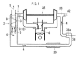
Fig. 1 , an exhaust treatment device for a diesel engine in which an exhaust flow divider (2) is provided in an exhaust path (1), the exhaust flow divider (2) causes an exhaust (3) to flow an EGR gas (4) with PM unevenly distributed and a remaining discharged gas (5) in a divided manner, the EGR gas (4) is recirculated to a combustion chamber (6), and the discharged gas (5) is discharged to an atmospheric side, wherein
as illustrated inFig. 2 orFig. 3 , a first corona discharge passage (7) and a second corona discharge passage (8) are provided at the exhaust flow divider (2),
corona discharge in the first corona discharge passage (7) causes the PM, water vapor, and oxygen in the exhaust (3) to generate electron attachment, and electrostatic force causes the exhaust (3) to flow the EGR gas (4) with the electron-attached PM, water vapor, and oxygen unevenly distributed and the remaining discharged gas (5) in a divided manner, the discharged gas (5) is guided to the second corona discharge passage (8), corona discharge in the second corona discharge passage (8) causes gas molecules in the discharged gas (5) to dissociate, and NOx in the discharged gas (5) is reduced to N2. - The first aspect of the present invention exhibits the following effects. «Effect» NOx concentration in the discharged gas can be greatly reduced.
- As illustrated in
Fig. 1 , since the water vapor is unevenly distributed in the EGR gas, as a combustion temperature of the combustion chamber (6) is reduced low by the water vapor having large specific heat, a generation amount of NOx can be reduced. - Since the water vapor and the oxygen are unevenly distributed in the EGR gas (4), a ratio of these components in the discharged gas (5) is reduced. Since the water vapor and the oxygen become inhibiting factors of a reduction reaction of the NOx by the corona discharge, the NOx in the discharged gas (5) with the reduced ratio of the water vapor and the oxygen is efficiently reduced to N2 by the corona discharge in the second corona discharge passage (8).
- From these reasons, the NOx concentration in the discharged gas (5) can be greatly reduced.
- Since the oxygen is unevenly distributed in the EGR gas (4), oxygen concentration in the combustion chamber (6) can be increased, and improvement of the engine output can be achieved due to the increase in a fuel injection amount.
- In addition to the effects of the first aspect of the present invention, the second aspect of the present invention exhibits the following effects.
- As illustrated in
Fig. 2 orFig. 3 , the electron-attached PM in the exhaust (3) swirling in an exhaust swirling passage (10) is unevenly distributed near an outer circumference wall (11) of the exhaust swirling passage (10) by electrostatic force and centrifugal force, and the EGR gas (4) containing the electron-attached PM unevenly distributed is caused to flow to an exhaust swirling passage end part (12) in a divided manner. Accordingly, the PM is unevenly distributed efficiently near the outer circumference wall (11) of the exhaust swirling passage (10), and the PM concentration in the EGR gas (4) can be enhanced. As a result, the PM is hardly discharged to an atmospheric side. - As illustrated in
Fig. 2 orFig. 3 , the electron-attached PM in the exhaust (3) swirling in the exhaust swirling passage (10) is unevenly distributed near the outer circumference wall (11) of the exhaust swirling passage (10) by electrostatic force and centrifugal force, and the EGR gas (4) containing the electron-attached PM unevenly distributed is caused to flow to the exhaust swirling passage end part (12) in a divided manner. Accordingly, both heavy PM on which the centrifugal force acts effectively, and light PM on which the electrostatic force acts effectively, can be uniformly taken into the EGR gas (4), and the PM having different weights or particle diameters can be taken into the EGR gas uniformly. As a result, the PM is hardly discharged to the atmospheric side. - In addition to the effects of the second aspect of the present invention, the third aspect of the present invention exhibits the following effect.
- As illustrated in
Fig. 2 orFig. 3 , a discharged gas entry port (13) is provided at a center cylinder (9) serving as a negative electrode of the first corona discharge passage (7), an interior of the center cylinder (9) serves as a discharged gas lead-out passage (14), and the discharged gas (5) near the center cylinder (9) in the exhaust swirling passage (10) is caused to flow from the discharged gas entry port (13) into the discharged gas lead-out passage (14) in a divided manner. Accordingly, the electron-attached PM, water vapor, and oxygen are kept away from the center cylinder (9) by electrostatic force, and these do not easily enter the discharged gas entry port (13). As a result, the PM, the water vapor, and the oxygen are hardly discharged into the atmosphere, and these are efficiently supplied to the combustion chamber (6) as unevenly distributed components of the EGR gas (4). - In addition to the effect of the third aspect of the present invention, the fourth aspect of the present invention exhibits the following effect.
- As illustrated in
Fig. 2 orFig. 3 , a swirling approach passage (19), the exhaust swirling passage (10) serving as the first corona discharge passage (7), the discharged gas lead-out passage (14), a discharged gas relay passage (18), and the second corona discharge passage (8) can be configured as a passage structure of concentric double cylinders, and the exhaust flow divider (2) can be configured compact. - In addition to the effects of any of the second to fourth aspects of the present invention, the fifth aspect of the present invention exhibits the following effect. «Effect» Backflow of the PM from an EGR swirling chamber to an exhaust swirling passage end part can be prevented.
- As illustrated in
Fig. 2 orFig. 3 , an EGR gas swirling chamber (20) is provided adjacent to the exhaust swirling passage end part (12), an EGR gas outlet (22) is provided on an EGR gas swirling chamber circumference wall (21) surrounding a periphery of the EGR gas swirling chamber (20), a partition (23) is provided between the exhaust swirling passage end part (12) and the EGR gas swirling chamber (20), and the EGR gas (4) is introduced from the exhaust swirling passage end part (12) to the EGR gas swirling chamber (20) via a gap between a peripheral edge part of this partition (23) and the EGR gas swirling chamber circumference wall (21). Accordingly, the EGR gas (4) does not short-circuit from the exhaust swirling passage end part (12) to the EGR gas outlet (22). Even in a case where supply of the EGR gas (4) to the combustion chamber (6) is stopped or reduced, swirling of the EGR gas (4) in the EGR gas swirling chamber (20) is maintained, and backflow of the PM from the EGR swirling chamber (20) to the exhaust swirling passage end part (12) can be prevented. - In addition to the effects of any of the first to fifth aspects of the present invention, the sixth aspect of the present invention exhibits the following effect. «Effect» It is not necessary to wire a high tension cable for supplying an electricity from a power supply to the electrode of each corona discharge passage outside the exhaust treatment device.
- As illustrated in
Fig. 2 orFig. 3 , a power supply relay box (24) is mounted to a lower end part of the exhaust flow divider (2), a power supply box (25) is mounted to a lateral side of this power supply relay box (24), an electric insulator (27) is provided on a lower end wall (26) of the exhaust flow divider (2), a conductor (28) penetrating the electric insulator (27) is introduced from the power supply relay box (24) to the exhaust flow divider (2), and a current is supplied from a power supply (29) in the power supply box (25) to the electrodes of the both corona discharge passages (7) (8) in the exhaust flow divider (2) via this conductor (28). Accordingly, it is not necessary to wire a high tension cable for supplying the electricity from the power supply (29) to the electrodes of the respective corona discharge passages (7) (8) outside the exhaust treatment device. - In addition to the effect of the sixth aspect of the present invention, the seventh aspect of the present invention exhibits the following effects.
- A pulse superposition type DC power supply is used for the power supply (29), and a DC current and a pulse current superposed on the DC current are supplied to the electrodes of the both corona discharge passages (7) (8) of the exhaust flow divider (2). Accordingly, the DC current is regularly leaked to soot attached to a surface of the electric insulator (27), excessive attachment of soot is prevented by heating and removing the soot using the leak current, corona discharge at an improper place generated by the soot serving as an electrode is suppressed, and efficient corona discharge at proper places in the respective corona discharge passages (7) (8) can be obtained.
- The pulse superposition type DC power supply is used for the power supply (29), and the DC current and the pulse current superposed on the DC current are supplied to the electrodes of the both corona discharge passages (7) (8) of the exhaust flow divider (2). Accordingly, a voltage boosting time of the current pulse is shortened, and the regulated pulse current waveform can be obtained.
- In addition to the effects of the sixth or seventh aspect of the present invention, the eighth aspect of the present invention exhibits the following effect. «Effect» Overheat of an inside of the power supply relay box is prevented.
- As illustrated in
Fig. 2 orFig. 3 , an outside air introduction port (30) is opened at a lower end part of the power supply relay box (24), an inside air lead-out port (31) is opened at an upper part of the power supply relay box (24), and due to convection of air by heat within the power supply relay box (24), an inside air (41) in the power supply relay box (24) is discharged from the inside air lead-out port (31), and an outside air (40) is introduced into the power supply relay box (24) from the outside air introduction port (30). Accordingly, ventilation inside the power supply relay box (24) is performed, and overheat of the inside of the power supply relay box (24) is prevented. - In addition to the effects of any of the sixth to eighth aspects of the present invention, the ninth aspect of the present invention exhibits the following effect. «Effect» Overheat of the power supply within the power supply box is prevented.
- As illustrated in
Fig. 2 , a clear air inlet (32) and an inside air outlet (33) are provided in the power supply box (25), the clean air inlet (32) is communicated with an air cleaner (34), the inside air outlet (33) is communicated with an air compressor inlet (36) of a supercharger (35), an inside air (43) within the power supply box (25) is discharged from the inside air outlet (33) with suction force of the supercharger (35), and a clean air (42) in the air cleaner (34) is introduced into the power supply box (25) from the clean air inlet (32). Accordingly, ventilation inside the power supply box (25) is performed, and overheat of the power supply (29) inside the power supply box (25) is prevented. - In addition to the effects of any of the sixth to ninth aspects of the present invention, the tenth aspect of the present invention exhibits the following effect. «Effect» The exhaust treatment device can be configured compact.
- As illustrated in
Fig. 2 ,Fig. 5 ,Figs. 6 (A) (B) , since the supercharger (35) positioned directly above the power supply box (25) is mounted on an upper lateral side of the exhaust flow divider (2), the exhaust treatment device can be configured compact. - In addition to the effects of any of the sixth to tenth aspects of the present invention, the eleventh aspect of the present invention exhibits the following effect. «Effect» The exhaust treatment device can be configured compact.
- As illustrated in
Fig. 5 andFig. 6(B) , an intake air inlet pipe (37) is mounted to the air compressor inlet (36) of the supercharger (35), an EGR valve case (38) is mounted to the intake air inlet pipe (37), an EGR cooler (39) positioned directly above the power supply box (25) is mounted on a lower lateral side of the exhaust flow divider (2), and the EGR gas outlet (22) of the exhaust flow divider (2) is communicated with the EGR valve case (38) via the EGR cooler (39). Accordingly, the exhaust treatment device can be configured compact. -
-
Fig. 1 is an exemplary diagram of an exhaust treatment device for a diesel engine according to an embodiment of the present invention. -
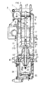
Fig. 2 is a longitudinal cross-sectional side view of a part of the exhaust treatment device for the diesel engine according to the embodiment of the present invention. -
Fig. 3 is a cross-sectional view taken along a line III-III inFig. 2 -
Fig. 4 is a diagram, as viewed from a IV direction inFig. 2 , of the device in which a supercharger or the like is removed from an exhaust flow divider and a power supply box is cut longitudinally. -
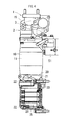
Fig. 5 is a side view of the exhaust treatment device for the diesel engine according to the embodiment of the present invention. -
Fig. 6(A) is a diagram of the device inFig. 5 as viewed from a VIA direction, andFig. 6(B) is a diagram of the device inFig. 5 as viewed from a VIB direction. -
Fig. 7(A) is a plan view of an engine main body, andFig. 7(B) is a plan view of the exhaust treatment device for the diesel engine according to the embodiment of the present invention, which is mounted on this engine main body. -
Figs. 1 to 7 are diagrams explaining an exhaust treatment device for a diesel engine according to an embodiment of the present invention. In this embodiment, an exhaust treatment device for a multi-cylinder diesel engine will be described. - As illustrated in
Fig. 1 , an exhaust flow divider (2) is provided in an exhaust path (1), the exhaust flow divider (2) causes an exhaust (3) to flow an EGR gas (4) with unevenly distributed PM and a remaining discharged gas (5) in a divided manner, the EGR gas (4) is recirculated to a combustion chamber (6), and the discharged gas (5) is discharged to an atmospheric side. - The EGR gas (4) is sucked into an air compressor inlet (36) of a supercharger (35) through an EGR cooler (39) and an EGR valve case (38). An arrow sign (42) in the drawing indicates a clean air from an air cleaner.
- As illustrated in
Fig. 2 orFig. 3 , a first corona discharge passage (7) and a second corona discharge passage (8) are provided at the exhaust flow divider (2), corona discharge in the first corona discharge passage (7) causes the PM, water vapor, and oxygen in the exhaust (3) to generate electron attachment, electrostatic force causes the exhaust (3) to flow the EGR gas (4) with the electron-attached PM, water vapor, and oxygen which are unevenly distributed and the remaining discharged gas (5) in a divided manner, the discharged gas (5) is guided to the second corona discharge passage (8), and corona discharge in the second corona discharge passage (8) causes gas molecules in the discharged gas (5) to dissociate, thereby reducing NOx in the discharged gas (5) to N2. - As illustrated in
Fig. 2 orFig. 3 , a center cylinder (9) is disposed at a center part of the exhaust flow divider (2), an exhaust swirling passage (10) is provided around this center cylinder (9), the exhaust swirling passage (10) serves as the first corona discharge passage (7), the center cylinder (9) serves as a negative electrode of the first corona discharge passage (7), and an outer circumference wall (11) of the exhaust swirling passage (10) serves as a positive electrode of the first corona discharge passage (7). - The electron-attached PM in the exhaust (3) swirling in the exhaust swirling passage (10) is unevenly distributed near the outer circumference wall (11) of the exhaust swirling passage (10) by electrostatic force and centrifugal force, and the EGR gas (4) containing the electron-attached PM unevenly distributed is caused to flow to an exhaust swirling passage end part (12) in a divided manner.
- As illustrated in
Fig. 3 , a plurality of needle-shaped projections (44) are arranged at an outer circumference of the center cylinder (9) serving as the negative electrode of the first corona discharge passage (7) in a circumferential direction, and this plurality of needle-shaped projections (44) is arranged in a plurality of rows in a passage forming direction of the first corona discharge passage (7). A negative polarity corona discharge is performed in this first corona discharge passage (7). - An inner diameter of the outer circumferential wall (11) around the center cylinder (9) is larger than other inner diameters in the exhaust flow divider (2), and reduction of a passage cross-sectional area by the needle-shaped projections (44) is recovered.
- As illustrated in
Fig. 2 orFig. 3 , a discharged gas entry port (13) is provided at the center cylinder (9) serving as the negative electrode of the first corona discharge passage (7), an interior of the center cylinder (9) serves as a discharged gas lead-out passage (14), and the discharged gas (5) near the center cylinder (9) in the exhaust swirling passage (10) is caused to flow from the discharged gas entry port (13) into the discharged gas lead-out passage (14) in a divided manner. - As illustrated in
Fig. 2 orFig. 3 , a downstream side center cylinder (15) concentric with the center cylinder (9) is provided on a downstream side of the center cylinder (9) in a discharged gas lead-out direction, an interior of this downstream side center cylinder (15) serves as the second corona discharge passage (8), the downstream side center cylinder (15) serves as a positive electrode of the second corona discharge passage (8), a core material (16) inserted into a center part of the downstream side center cylinder (15) serves as a negative electrode of the second corona discharge passage (8), a relay cylinder (17) serving as an electric insulator is interposed between the center cylinder (9) and the downstream side center cylinder (15), an interior of the relay cylinder (17) serves as a discharged gas relay passage (18), the discharged gas lead-out passage (14) and the second corona discharge passage (8) are communicated with each other via this discharged gas relay passage (18), the core material (16) is electrically connected with the center cylinder (9), and an outside of the downstream side center cylinder (15) serves as a swirling approach passage (19) positioned on an exhaust upstream side of the exhaust swirling passage (10). - As illustrated in
Fig. 3 , a plurality of needle-shaped projections (46) are arranged at an outer circumference of the core material (16) serving as a negative electrode of the second corona discharge passage (8) in a circumferential direction, and this plurality of needle-shaped projections (46) are arranged in a plurality of rows in a passage forming direction of the second corona discharge passage (8). A negative polarity corona discharge is performed in this second corona discharge passage (8). - As irregularities are provided at an outer circumference of the relay cylinder (17) and a surface area of the relay cylinder (17) is increased, an attachment area of soot attached to the relay cylinder (17) is increased. Accordingly, electric resistance of the soot is enhanced, and occurrence of an excessive leak current is prevented.
- A spiral guide vane (45) is internally installed in the swirling approach passage (19).
- As illustrated in
Fig. 2 orFig. 3 , an EGR gas swirling chamber (20) is provided adjacent to the exhaust swirling passage end part (12), an EGR gas outlet (22) is provided on an EGR gas swirling chamber circumference wall (21) surrounding a periphery of the EGR gas swirling chamber (20), a partition (23) is provided between the exhaust swirling passage end part (12) and the EGR gas swirling chamber (20), and the EGR gas (4) is introduced from the exhaust swirling passage end part (12) to the EGR gas swirling chamber (20) via a gap between a peripheral edge part of this partition (23) and the EGR gas swirling chamber circumference wall (21). - As illustrated in
Fig. 2 orFig. 3 , a power supply relay box (24) is mounted to a lower end part of the exhaust flow divider (2), a power supply box (25) is mounted to a lateral side of this power supply relay box (24), an electric insulator (27) is provided on a lower end wall (26) of the exhaust flow divider (2), a conductor (28) penetrating the electric insulator (27) is introduced from the power supply relay box (24) to the exhaust flow divider (2), and a current is supplied from a power supply (29) in the power supply box (25) to the electrodes of the both corona discharge passages (7) (8) in the exhaust flow divider (2) via this conductor (28). - In the power supply relay box (24), electrical connection between the power supply (29) and the conductor (28) is performed via a conductive piece (53).
- As illustrated in
Fig. 2 orFig. 3 , the exhaust flow divider (2) has a double cylinder structure which is long in an up and down direction, and on an outer circumferential side, the swirling approach passage (19), the first corona discharge passage (7) serving as a part of the exhaust swirling passage (10), the exhaust swirling passage circumferential end part (12), and the EGR gas swirling chamber (20) are disposed in this order from above, and on a center side, the discharged gas lead-out passage (14), the discharged gas relay passage (18), and the second corona discharge passage (8) are disposed in this order from below. As illustrated inFig. 2 , the second corona discharge passage (8) is communicated with an exhaust muffler (52) disposed downstream thereof. - As irregularities are provided at an outer circumference of a part of the electric insulator (27) within the exhaust swirling passage end part (12) and a surface area of the electric insulator (27) is increased, an area of soot attached to the electric insulator (27) is increased. Accordingly, electric resistance of the soot is enhanced, and occurrence of an excessive leak current is prevented.
- A pulse superposition type DC power supply is used for the power supply (29), and a DC current and a pulse current superposed on the DC current are supplied to the electrodes of the both corona discharge passages (7) (8) of the exhaust flow divider (2).
- As illustrated in
Fig. 2 orFig. 3 , an outside air introduction port (30) is opened at a lower end part of the power supply relay box (24), an inside air lead-out port (31) is opened at an upper part of the power supply relay box (24), and due to convection of air by heat within the power supply relay box (24), an inside air (41) in the power supply relay box (24) is discharged from the inside air lead-out port (31), and an outside air (40) is introduced into the power supply relay box (24) from the outside air introduction port (30). - As illustrated in
Fig. 2 , a clear air inlet (32) and an inside air outlet (33) are provided in the power supply box (25), the clean air inlet (32) is communicated with an air cleaner (34), the inside air outlet (33) is communicated with the air compressor inlet (36) of the supercharger (35), an inside air (43) within the power supply box (25) is discharged from the inside air outlet (33) with suction force of the supercharger (35), and a clean air (42) in the air cleaner (34) is introduced into the power supply box (25) from the clean air inlet (32). - As illustrated in
Fig. 2 ,Fig. 5 , andFigs. 6(A) (B) , the supercharger (35) positioned directly above the power supply box (25) is mounted on an upper lateral side of the exhaust flow divider (2). - The exhaust separator (2) is long in the up and down direction.
- As illustrated in
Figs. 7(A) (B) , the supercharger (35) is mounted on an exhaust manifold (51) mounted on a cylinder head (50). - As illustrated in
Fig. 5 andFig. 6(B) , an intake air inlet pipe (37) is mounted to the air compressor inlet (36) of the supercharger (35), the EGR valve case (38) is mounted to this intake air inlet pipe (37), the EGR cooler (39) positioned directly above the power supply box (25) is mounted on a lower lateral side of the exhaust flow divider (2), and the EGR gas outlet (22) in the exhaust flow divider (2) is communicated with the EGR valve case (38) via the EGR cooler (39). - A breather pipe (49) is communicated with the intake air inlet pipe (37), and a blowby gas (55) is introduced into the intake air inlet pipe (37).
- A valve driving actuator (47) of an EGR valve (38a) is mounted on an upper part of the EGR valve case (38).
- An engine cooling water (54) is supplied from a cooling water jacket (not illustrated) of the cylinder head (50) to the EGR cooler (39) via an engine cooling water outlet part (48).
-
- (1):
- Exhaust path
- (2):
- Exhaust flow divider
- (3):
- Exhaust
- (4):
- EGR gas
- (5):
- Discharged gas
- (6):
- Combustion chamber
- (7):
- First corona discharge passage
- (8):
- Second corona discharge passage
- (9):
- Center cylinder
- (10):
- Exhaust swirling passage
- (11):
- Outer circumference wall
- (12):
- Exhaust swirling passage end part
- (13):
- Discharged gas entry port
- (14):
- Discharged gas lead-out passage
- (15):
- Downstream side center cylinder
- (16):
- Core material
- (17):
- Relay cylinder
- (18):
- Discharged gas relay passage
- (19):
- Swirling approach passage
- (20):
- EGR gas swirling chamber
- (21):
- EGR gas swirling chamber circumference wall
- (22):
- EGR gas outlet
- (23):
- Partition
- (24):
- Power supply relay box
- (25):
- Power supply box
- (26):
- Lower end wall
- (27):
- Electric insulator
- (28):
- Conductor
- (29):
- Power supply
- (30):
- Outside air introduction port
- (31):
- Inside air lead-out port
- (32):
- Clean air inlet
- (33):
- Inside air outlet
- (34):
- Air cleaner
- (35):
- Supercharger
- (36):
- Air compressor inlet
- (37):
- Intake air inlet pipe
- (38):
- EGR valve case
- (39):
- EGR cooler
- (40):
- Outside air
- (41):
- Inside air
- (42):
- Clear air
- (43):
- Inside air
Claims (11)
- An exhaust treatment device for a diesel engine in which an exhaust flow divider (2) is provided in an exhaust path (1), the exhaust flow divider (2) causes an exhaust (3) to flow an EGR gas (4) with PM unevenly distributed and a remaining discharged gas 5 in a divided manner, the EGR gas 4 is recirculated to a combustion chamber 6, and the discharged gas (5) is discharged to an atmospheric side, wherein
a first corona discharge passage (7) and a second corona discharge passage (8) are provided at the exhaust flow divider (2), corona discharge in the first corona discharge passage (7) causes the PM, water vapor, and oxygen in the exhaust (3) to generate electron attachment, and electrostatic force causes the exhaust (3) to flow the EGR gas (4) with the electron-attached PM, water vapor, and oxygen unevenly distributed and the remaining discharged gas (5) in a divided manner, the discharged gas (5) is guided to the second corona discharge passage (8), corona discharge in the second corona discharge passage (8) causes gas molecules in the discharged gas (5) to dissociate, and NOx in the discharged gas (5) is reduced to N2. - The exhaust treatment device for the diesel engine according to claim 1, wherein a center cylinder (9) is disposed at a center part of the exhaust flow divider (2), an exhaust swirling passage (10) is provided around this center cylinder (9), the exhaust swirling passage (10) serves as the first corona discharge passage (7), the center cylinder (9) serves as a negative electrode of the first corona discharge passage (7), an outer circumference wall (11) of the exhaust swirling passage (10) serves as a positive electrode of the first corona discharge passage (7),
the electron-attached PM in the exhaust (3) swirling in the exhaust swirling passage (10) is unevenly distributed near the outer circumference wall (11) of the exhaust swirling passage (10) by electrostatic force and centrifugal force, and the EGR gas (4) containing the electron-attached PM unevenly distributed is caused to flow into an exhaust swirling passage end part (12) in a divided manner. - The exhaust treatment device for the diesel engine according to claim 2, wherein a discharged gas entry port (13) is provided at the center cylinder (9) serving as the negative electrode of the first corona discharge passage (7), an interior of the center cylinder (9) serves as a discharged gas lead-out passage (14), and the discharged gas (5) near the center cylinder (9) in the exhaust swirling passage (10) is caused to flow from the discharged gas entry port (13) into the discharged gas lead-out passage (14) in a divided manner.
- The exhaust treatment device for the diesel engine according to claim 3, wherein a downstream side center cylinder (15) concentric with the center cylinder (9) is provided on a downstream side of the center cylinder (9) in a discharged gas lead-out direction, an interior of this downstream side center cylinder (15) serves as the second corona discharge passage (8), the downstream side center cylinder (15) serves as a positive electrode of the second corona discharge passage (8), a core material (16) inserted into a center part of the downstream side center cylinder (15) serves as a negative electrode of the second corona discharge passage (8), a relay cylinder (17) serving as an electric insulator is interposed between the center cylinder (9) and the downstream side center cylinder (15), an interior of the relay cylinder (17) serves as a discharged gas relay passage (18), the discharged gas lead-out passage (14) and the second corona discharge passage (8) are communicated with each other via the discharged gas relay passage (18), the core material (16) is electrically connected with the center cylinder (9), and an outside of the downstream side center cylinder (15) serves as a swirling approach passage (19) positioned on an exhaust upstream side of the exhaust swirling passage (10).
- The exhaust treatment device for the diesel engine according to any of claim 2 to claim 4, wherein an EGR gas swirling chamber (20) is provided adjacent to the exhaust swirling passage end part (12), an EGR gas outlet (22) is provided on an EGR gas swirling chamber circumference wall (21) surrounding a periphery of the EGR gas swirling chamber (20), a partition (23) is provided between the exhaust swirling passage end part (12) and the EGR gas swirling chamber (20), and the EGR gas (4) is introduced from the exhaust swirling passage end part (12) to the EGR gas swirling chamber (20) via a gap between a peripheral edge part of this partition (23) and the gas swirling chamber circumference wall (21).
- The exhaust treatment device for the diesel engine according to any of claim 1 to claim 5, wherein a power supply relay box (24) is mounted to a lower end part of the exhaust flow divider (2), a power supply box (25) is mounted to a lateral side of this power supply relay box (24), an electric insulator (27) is provided on a lower end wall (26) of the exhaust flow divider (2), a conductor (28) penetrating the electric insulator (27) is introduced from the power supply relay box (24) to the exhaust flow divider (2), and a current is supplied from a power supply (29) in the power supply box (25) to the electrodes of the both corona discharge passages (7) (8) in the exhaust flow divider (2) via this conductor (28).
- The exhaust treatment device for the diesel engine according to claim 6, wherein a pulse superposition type DC power supply is used for the power supply (29), and a DC current and a pulse current superposed on the DC current are supplied to the electrodes of the both corona discharge passages (7) (8) of the exhaust flow divider (2).
- The exhaust treatment device for the diesel engine according to claim 6 or claim 7, wherein an outside air introduction port (30) is opened at a lower end part of the power supply relay box (24), an inside air lead-out port (31) is opened at an upper part of the power supply relay box (24), and due to convection of air by heat within the power supply relay box (24), an inside air (41) in the power supply relay box (24) is discharged from the inside air lead-out port (31), and an outside air (40) is introduced into the power supply relay box (24) from the outside air introduction port (30).
- The exhaust treatment device for the diesel engine according to any of claim 6 to claim 8, wherein a clear air inlet (32) and an inside air outlet (33) are provided in the power supply box (25), the clean air inlet (32) is communicated with an air cleaner (34), the inside air outlet (33) is communicated with an air compressor inlet (36) of a supercharger (35), an inside air (43) within the power supply box (25) is discharged from the inside air outlet (33) with suction force of the supercharger (35), and a clean air (42) of the air cleaner (34) is introduced into the power supply box (25) from the clean air inlet (32).
- The exhaust treatment device for the diesel engine according to any of claim 6 to claim 9, wherein the supercharger (35) positioned directly above the power supply box (25) is mounted on an upper lateral side of the exhaust flow divider (2).
- The exhaust treatment device for the diesel engine according to any of claim 6 to claim 10, wherein an intake air inlet pipe (37) is mounted to the air compressor inlet (36) of the supercharger (35), an EGR valve case (38) is mounted to the intake air inlet pipe (37), an EGR cooler (39) positioned directly above the power supply box (25) is mounted on a lower lateral side of the exhaust flow divider (2), and the EGR gas outlet (22) of the exhaust flow divider (2) is communicated with the EGR valve case (38) via the EGR cooler (39).
Applications Claiming Priority (2)
| Application Number | Priority Date | Filing Date | Title |
|---|---|---|---|
| JP2012080834A JP5806967B2 (en) | 2012-03-30 | 2012-03-30 | Diesel engine exhaust treatment equipment |
| PCT/JP2013/054718 WO2013145994A1 (en) | 2012-03-30 | 2013-02-25 | Exhaust treatment device for diesel engine |
Publications (3)
| Publication Number | Publication Date |
|---|---|
| EP2832961A1 true EP2832961A1 (en) | 2015-02-04 |
| EP2832961A4 EP2832961A4 (en) | 2015-11-18 |
| EP2832961B1 EP2832961B1 (en) | 2017-08-23 |
Family
ID=49259273
Family Applications (1)
| Application Number | Title | Priority Date | Filing Date |
|---|---|---|---|
| EP13768358.7A Not-in-force EP2832961B1 (en) | 2012-03-30 | 2013-02-25 | Exhaust treatment device for diesel engine |
Country Status (4)
| Country | Link |
|---|---|
| US (1) | US9347351B2 (en) |
| EP (1) | EP2832961B1 (en) |
| JP (1) | JP5806967B2 (en) |
| WO (1) | WO2013145994A1 (en) |
Families Citing this family (4)
| Publication number | Priority date | Publication date | Assignee | Title |
|---|---|---|---|---|
| JP5427739B2 (en) * | 2010-09-17 | 2014-02-26 | 株式会社クボタ | Diesel engine exhaust treatment equipment |
| CN106194335A (en) * | 2015-05-04 | 2016-12-07 | 黄斌 | A kind of automobile exhaust gas purifying installation |
| CN106499551B (en) * | 2016-10-12 | 2017-07-28 | 同济大学 | A Clean EGR Loop System |
| CN111810274B (en) * | 2020-07-16 | 2022-01-21 | 平湖爱之馨环保科技有限公司 | Automobile exhaust purification device |
Family Cites Families (24)
| Publication number | Priority date | Publication date | Assignee | Title |
|---|---|---|---|---|
| JPS56129846U (en) * | 1980-02-29 | 1981-10-02 | ||
| DE3019991A1 (en) * | 1980-05-24 | 1981-12-03 | Robert Bosch Gmbh, 7000 Stuttgart | METHOD AND DEVICE FOR REMOVING SOLID COMPONENTS FROM THE EXHAUST GAS FROM COMBUSTION ENGINE, IN PARTICULAR SOOT COMPONENTS |
| DE3141156A1 (en) * | 1981-10-16 | 1983-04-28 | Robert Bosch Gmbh, 7000 Stuttgart | METHOD AND DEVICE FOR REMOVING SOLID COMPONENTS AND AEROSOLS, ESPECIALLY SOOT COMPONENTS FROM THE EXHAUST GAS FROM COMBUSTION ENGINES |
| US4588423A (en) * | 1982-06-30 | 1986-05-13 | Donaldson Company, Inc. | Electrostatic separator |
| US4587807A (en) * | 1983-04-18 | 1986-05-13 | Nagatoshi Suzuki | Apparatus for totally recycling engine exhaust gas |
| DE3500375A1 (en) * | 1985-01-08 | 1986-07-10 | Robert Bosch Gmbh, 7000 Stuttgart | DEVICE FOR REMOVING SOLID PARTICLES, ESPECIALLY CARBON PARTICLES, FROM THE EXHAUST GAS FROM COMBUSTION ENGINES |
| DE4319283C1 (en) * | 1993-06-10 | 1994-10-20 | Daimler Benz Ag | Method and device for reducing particles in exhaust gases |
| JPH0791328A (en) * | 1993-07-30 | 1995-04-04 | Mitsubishi Motors Corp | EGR gas charging device |
| US6092512A (en) * | 1996-07-26 | 2000-07-25 | Ford Global Technologies, Inc. | Internal combustion engine |
| JP4107625B2 (en) * | 1999-03-31 | 2008-06-25 | 東京瓦斯株式会社 | Exhaust gas recirculation device for internal combustion engine |
| JP2003178814A (en) * | 2001-12-10 | 2003-06-27 | Inoac Corp | Battery cooling device |
| JP3875571B2 (en) * | 2002-02-19 | 2007-01-31 | 西松建設株式会社 | Exhaust gas treatment apparatus and exhaust gas treatment method |
| US7267711B2 (en) * | 2003-09-23 | 2007-09-11 | Msp Corporation | Electrostatic precipitator for diesel blow-by |
| JP2005291071A (en) | 2004-03-31 | 2005-10-20 | Honda Motor Co Ltd | Exhaust gas purification system and exhaust gas purification method |
| US7356987B2 (en) * | 2004-07-30 | 2008-04-15 | Caterpillar Inc. | Exhaust gas recirculation system having an electrostatic precipitator |
| JP2007278194A (en) * | 2006-04-07 | 2007-10-25 | Hino Motors Ltd | Exhaust treatment device |
| JP4325714B2 (en) * | 2007-09-28 | 2009-09-02 | ダイキン工業株式会社 | Refrigeration equipment |
| JP2011202506A (en) * | 2008-07-23 | 2011-10-13 | Kubota Corp | Diesel engine |
| EP2390380B1 (en) * | 2008-12-26 | 2016-03-09 | Canon Anelva Corporation | Sputtering equipment, sputtering method and method for manufacturing an electronic device |
| JP5351791B2 (en) * | 2009-04-30 | 2013-11-27 | 株式会社クボタ | Diesel engine exhaust treatment equipment |
| JP5407733B2 (en) * | 2009-10-16 | 2014-02-05 | 株式会社デンソー | Exhaust purification device |
| JP5427739B2 (en) * | 2010-09-17 | 2014-02-26 | 株式会社クボタ | Diesel engine exhaust treatment equipment |
| KR101251513B1 (en) * | 2010-12-06 | 2013-04-05 | 기아자동차주식회사 | Method for controlling an engine provided with lp-egr |
| DE102011089489B4 (en) * | 2011-12-21 | 2014-01-02 | Continental Automotive Gmbh | Cooling of an electrical energy storage means by means of an intake air of an internal combustion engine |
-
2012
- 2012-03-30 JP JP2012080834A patent/JP5806967B2/en not_active Expired - Fee Related
-
2013
- 2013-02-25 WO PCT/JP2013/054718 patent/WO2013145994A1/en not_active Ceased
- 2013-02-25 EP EP13768358.7A patent/EP2832961B1/en not_active Not-in-force
- 2013-02-25 US US14/383,152 patent/US9347351B2/en not_active Expired - Fee Related
Also Published As
| Publication number | Publication date |
|---|---|
| WO2013145994A1 (en) | 2013-10-03 |
| EP2832961B1 (en) | 2017-08-23 |
| JP2013209939A (en) | 2013-10-10 |
| US9347351B2 (en) | 2016-05-24 |
| EP2832961A4 (en) | 2015-11-18 |
| JP5806967B2 (en) | 2015-11-10 |
| US20150033708A1 (en) | 2015-02-05 |
Similar Documents
| Publication | Publication Date | Title |
|---|---|---|
| CN102362049B (en) | Waste gas treatment device of diesel engine | |
| EP2832961B1 (en) | Exhaust treatment device for diesel engine | |
| EP2868880B1 (en) | Exhaust gas treatment device for marine diesel engine using fuel of lower quality than heavy oil | |
| US8308846B2 (en) | Method and device for precipitating impurities from a stream of gas | |
| US8157902B2 (en) | Non-thermal plasma particulate removal systems and methods thereof | |
| BRPI0716322A2 (en) | METHOD OF REDUCING INJECTOR FUEL PARTICULATE SIZE, APPARATUS FOR REDUCING FUEL PARTICULATE SIZE IN A FULL DIMENSION METHOD OF INCREASE METHODS COMBUSTION AND METHOD OF IMPROVEMENT OF ENGINE EMISSIONS TO COMBUSTION | |
| JP2010276012A5 (en) | ||
| JP2007107491A (en) | Combustion accelerating air treatment device for displacement type internal combustion engine | |
| CN108554631B (en) | Coaxial Multistage NTP Generator Based on Dielectric Barrier Discharge | |
| JP2009167997A (en) | Exhaust gas recirculation equipment of internal combustion engine | |
| RU154119U1 (en) | DEVICE FOR CLEANING AND RECYCLING EXHAUST GASES | |
| JP5531978B2 (en) | Exhaust treatment device for internal combustion engine | |
| CN201071770Y (en) | Ozone generating device for engine | |
| US20080118410A1 (en) | Exhaust Gas Cleaner | |
| JP5427739B2 (en) | Diesel engine exhaust treatment equipment | |
| JP2004340048A (en) | EGR device | |
| RU2708218C2 (en) | Method for optimizing combustion in fuel combustion devices and device for carrying out method | |
| JP6193734B2 (en) | Particle charged exhaust purification system | |
| CN212744120U (en) | Electrostatic adsorption particle catcher | |
| CN2668879Y (en) | Gas purification device for internal combustion engine | |
| CN206158822U (en) | Processing apparatus , diesel engine and car behind low temperature plasma | |
| JP2014013020A (en) | Internal combustion engine | |
| WO2022094991A1 (en) | Internal combustion engine with particle charging device | |
| JP2021042736A (en) | Blow-by gas recirculation device for internal combustion engine | |
| CN2799878Y (en) | Energy saving device of internal combustion engine |
Legal Events
| Date | Code | Title | Description |
|---|---|---|---|
| PUAI | Public reference made under article 153(3) epc to a published international application that has entered the european phase |
Free format text: ORIGINAL CODE: 0009012 |
|
| 17P | Request for examination filed |
Effective date: 20140807 |
|
| AK | Designated contracting states |
Kind code of ref document: A1 Designated state(s): AL AT BE BG CH CY CZ DE DK EE ES FI FR GB GR HR HU IE IS IT LI LT LU LV MC MK MT NL NO PL PT RO RS SE SI SK SM TR |
|
| AX | Request for extension of the european patent |
Extension state: BA ME |
|
| DAX | Request for extension of the european patent (deleted) | ||
| RA4 | Supplementary search report drawn up and despatched (corrected) |
Effective date: 20151015 |
|
| RIC1 | Information provided on ipc code assigned before grant |
Ipc: F01N 3/02 20060101ALI20151009BHEP Ipc: F01N 3/01 20060101AFI20151009BHEP Ipc: F02D 21/08 20060101ALI20151009BHEP Ipc: F01N 3/037 20060101ALI20151009BHEP Ipc: F02M 25/07 20060101ALI20151009BHEP Ipc: F01N 3/08 20060101ALI20151009BHEP Ipc: F02D 23/00 20060101ALI20151009BHEP |
|
| REG | Reference to a national code |
Ref country code: DE Ref legal event code: R079 Ref document number: 602013025516 Country of ref document: DE Free format text: PREVIOUS MAIN CLASS: F01N0003010000 Ipc: F02M0026000000 |
|
| GRAP | Despatch of communication of intention to grant a patent |
Free format text: ORIGINAL CODE: EPIDOSNIGR1 |
|
| RIC1 | Information provided on ipc code assigned before grant |
Ipc: F02M 26/00 20160101AFI20170118BHEP |
|
| INTG | Intention to grant announced |
Effective date: 20170216 |
|
| GRAJ | Information related to disapproval of communication of intention to grant by the applicant or resumption of examination proceedings by the epo deleted |
Free format text: ORIGINAL CODE: EPIDOSDIGR1 |
|
| INTC | Intention to grant announced (deleted) | ||
| GRAR | Information related to intention to grant a patent recorded |
Free format text: ORIGINAL CODE: EPIDOSNIGR71 |
|
| GRAS | Grant fee paid |
Free format text: ORIGINAL CODE: EPIDOSNIGR3 |
|
| GRAA | (expected) grant |
Free format text: ORIGINAL CODE: 0009210 |
|
| INTG | Intention to grant announced |
Effective date: 20170713 |
|
| AK | Designated contracting states |
Kind code of ref document: B1 Designated state(s): AL AT BE BG CH CY CZ DE DK EE ES FI FR GB GR HR HU IE IS IT LI LT LU LV MC MK MT NL NO PL PT RO RS SE SI SK SM TR |
|
| REG | Reference to a national code |
Ref country code: GB Ref legal event code: FG4D |
|
| REG | Reference to a national code |
Ref country code: CH Ref legal event code: EP |
|
| REG | Reference to a national code |
Ref country code: AT Ref legal event code: REF Ref document number: 921622 Country of ref document: AT Kind code of ref document: T Effective date: 20170915 |
|
| REG | Reference to a national code |
Ref country code: IE Ref legal event code: FG4D |
|
| REG | Reference to a national code |
Ref country code: DE Ref legal event code: R096 Ref document number: 602013025516 Country of ref document: DE |
|
| REG | Reference to a national code |
Ref country code: NL Ref legal event code: MP Effective date: 20170823 |
|
| REG | Reference to a national code |
Ref country code: LT Ref legal event code: MG4D |
|
| REG | Reference to a national code |
Ref country code: FR Ref legal event code: PLFP Year of fee payment: 6 |
|
| REG | Reference to a national code |
Ref country code: AT Ref legal event code: MK05 Ref document number: 921622 Country of ref document: AT Kind code of ref document: T Effective date: 20170823 |
|
| PG25 | Lapsed in a contracting state [announced via postgrant information from national office to epo] |
Ref country code: FI Free format text: LAPSE BECAUSE OF FAILURE TO SUBMIT A TRANSLATION OF THE DESCRIPTION OR TO PAY THE FEE WITHIN THE PRESCRIBED TIME-LIMIT Effective date: 20170823 Ref country code: LT Free format text: LAPSE BECAUSE OF FAILURE TO SUBMIT A TRANSLATION OF THE DESCRIPTION OR TO PAY THE FEE WITHIN THE PRESCRIBED TIME-LIMIT Effective date: 20170823 Ref country code: HR Free format text: LAPSE BECAUSE OF FAILURE TO SUBMIT A TRANSLATION OF THE DESCRIPTION OR TO PAY THE FEE WITHIN THE PRESCRIBED TIME-LIMIT Effective date: 20170823 Ref country code: NL Free format text: LAPSE BECAUSE OF FAILURE TO SUBMIT A TRANSLATION OF THE DESCRIPTION OR TO PAY THE FEE WITHIN THE PRESCRIBED TIME-LIMIT Effective date: 20170823 Ref country code: NO Free format text: LAPSE BECAUSE OF FAILURE TO SUBMIT A TRANSLATION OF THE DESCRIPTION OR TO PAY THE FEE WITHIN THE PRESCRIBED TIME-LIMIT Effective date: 20171123 Ref country code: SE Free format text: LAPSE BECAUSE OF FAILURE TO SUBMIT A TRANSLATION OF THE DESCRIPTION OR TO PAY THE FEE WITHIN THE PRESCRIBED TIME-LIMIT Effective date: 20170823 Ref country code: AT Free format text: LAPSE BECAUSE OF FAILURE TO SUBMIT A TRANSLATION OF THE DESCRIPTION OR TO PAY THE FEE WITHIN THE PRESCRIBED TIME-LIMIT Effective date: 20170823 |
|
| PG25 | Lapsed in a contracting state [announced via postgrant information from national office to epo] |
Ref country code: PL Free format text: LAPSE BECAUSE OF FAILURE TO SUBMIT A TRANSLATION OF THE DESCRIPTION OR TO PAY THE FEE WITHIN THE PRESCRIBED TIME-LIMIT Effective date: 20170823 Ref country code: BG Free format text: LAPSE BECAUSE OF FAILURE TO SUBMIT A TRANSLATION OF THE DESCRIPTION OR TO PAY THE FEE WITHIN THE PRESCRIBED TIME-LIMIT Effective date: 20171123 Ref country code: RS Free format text: LAPSE BECAUSE OF FAILURE TO SUBMIT A TRANSLATION OF THE DESCRIPTION OR TO PAY THE FEE WITHIN THE PRESCRIBED TIME-LIMIT Effective date: 20170823 Ref country code: LV Free format text: LAPSE BECAUSE OF FAILURE TO SUBMIT A TRANSLATION OF THE DESCRIPTION OR TO PAY THE FEE WITHIN THE PRESCRIBED TIME-LIMIT Effective date: 20170823 Ref country code: GR Free format text: LAPSE BECAUSE OF FAILURE TO SUBMIT A TRANSLATION OF THE DESCRIPTION OR TO PAY THE FEE WITHIN THE PRESCRIBED TIME-LIMIT Effective date: 20171124 Ref country code: ES Free format text: LAPSE BECAUSE OF FAILURE TO SUBMIT A TRANSLATION OF THE DESCRIPTION OR TO PAY THE FEE WITHIN THE PRESCRIBED TIME-LIMIT Effective date: 20170823 Ref country code: IS Free format text: LAPSE BECAUSE OF FAILURE TO SUBMIT A TRANSLATION OF THE DESCRIPTION OR TO PAY THE FEE WITHIN THE PRESCRIBED TIME-LIMIT Effective date: 20171223 |
|
| PG25 | Lapsed in a contracting state [announced via postgrant information from national office to epo] |
Ref country code: CZ Free format text: LAPSE BECAUSE OF FAILURE TO SUBMIT A TRANSLATION OF THE DESCRIPTION OR TO PAY THE FEE WITHIN THE PRESCRIBED TIME-LIMIT Effective date: 20170823 Ref country code: DK Free format text: LAPSE BECAUSE OF FAILURE TO SUBMIT A TRANSLATION OF THE DESCRIPTION OR TO PAY THE FEE WITHIN THE PRESCRIBED TIME-LIMIT Effective date: 20170823 Ref country code: RO Free format text: LAPSE BECAUSE OF FAILURE TO SUBMIT A TRANSLATION OF THE DESCRIPTION OR TO PAY THE FEE WITHIN THE PRESCRIBED TIME-LIMIT Effective date: 20170823 |
|
| REG | Reference to a national code |
Ref country code: DE Ref legal event code: R097 Ref document number: 602013025516 Country of ref document: DE |
|
| PG25 | Lapsed in a contracting state [announced via postgrant information from national office to epo] |
Ref country code: EE Free format text: LAPSE BECAUSE OF FAILURE TO SUBMIT A TRANSLATION OF THE DESCRIPTION OR TO PAY THE FEE WITHIN THE PRESCRIBED TIME-LIMIT Effective date: 20170823 Ref country code: SK Free format text: LAPSE BECAUSE OF FAILURE TO SUBMIT A TRANSLATION OF THE DESCRIPTION OR TO PAY THE FEE WITHIN THE PRESCRIBED TIME-LIMIT Effective date: 20170823 Ref country code: SM Free format text: LAPSE BECAUSE OF FAILURE TO SUBMIT A TRANSLATION OF THE DESCRIPTION OR TO PAY THE FEE WITHIN THE PRESCRIBED TIME-LIMIT Effective date: 20170823 Ref country code: IT Free format text: LAPSE BECAUSE OF FAILURE TO SUBMIT A TRANSLATION OF THE DESCRIPTION OR TO PAY THE FEE WITHIN THE PRESCRIBED TIME-LIMIT Effective date: 20170823 |
|
| PLBE | No opposition filed within time limit |
Free format text: ORIGINAL CODE: 0009261 |
|
| STAA | Information on the status of an ep patent application or granted ep patent |
Free format text: STATUS: NO OPPOSITION FILED WITHIN TIME LIMIT |
|
| 26N | No opposition filed |
Effective date: 20180524 |
|
| PG25 | Lapsed in a contracting state [announced via postgrant information from national office to epo] |
Ref country code: SI Free format text: LAPSE BECAUSE OF FAILURE TO SUBMIT A TRANSLATION OF THE DESCRIPTION OR TO PAY THE FEE WITHIN THE PRESCRIBED TIME-LIMIT Effective date: 20170823 |
|
| REG | Reference to a national code |
Ref country code: CH Ref legal event code: PL |
|
| PG25 | Lapsed in a contracting state [announced via postgrant information from national office to epo] |
Ref country code: MC Free format text: LAPSE BECAUSE OF FAILURE TO SUBMIT A TRANSLATION OF THE DESCRIPTION OR TO PAY THE FEE WITHIN THE PRESCRIBED TIME-LIMIT Effective date: 20170823 |
|
| REG | Reference to a national code |
Ref country code: IE Ref legal event code: MM4A |
|
| REG | Reference to a national code |
Ref country code: BE Ref legal event code: MM Effective date: 20180228 |
|
| PG25 | Lapsed in a contracting state [announced via postgrant information from national office to epo] |
Ref country code: LU Free format text: LAPSE BECAUSE OF NON-PAYMENT OF DUE FEES Effective date: 20180225 Ref country code: LI Free format text: LAPSE BECAUSE OF NON-PAYMENT OF DUE FEES Effective date: 20180228 Ref country code: CH Free format text: LAPSE BECAUSE OF NON-PAYMENT OF DUE FEES Effective date: 20180228 |
|
| PG25 | Lapsed in a contracting state [announced via postgrant information from national office to epo] |
Ref country code: IE Free format text: LAPSE BECAUSE OF NON-PAYMENT OF DUE FEES Effective date: 20180225 |
|
| PG25 | Lapsed in a contracting state [announced via postgrant information from national office to epo] |
Ref country code: BE Free format text: LAPSE BECAUSE OF NON-PAYMENT OF DUE FEES Effective date: 20180228 |
|
| PG25 | Lapsed in a contracting state [announced via postgrant information from national office to epo] |
Ref country code: MT Free format text: LAPSE BECAUSE OF NON-PAYMENT OF DUE FEES Effective date: 20180225 |
|
| PG25 | Lapsed in a contracting state [announced via postgrant information from national office to epo] |
Ref country code: TR Free format text: LAPSE BECAUSE OF FAILURE TO SUBMIT A TRANSLATION OF THE DESCRIPTION OR TO PAY THE FEE WITHIN THE PRESCRIBED TIME-LIMIT Effective date: 20170823 |
|
| PG25 | Lapsed in a contracting state [announced via postgrant information from national office to epo] |
Ref country code: PT Free format text: LAPSE BECAUSE OF FAILURE TO SUBMIT A TRANSLATION OF THE DESCRIPTION OR TO PAY THE FEE WITHIN THE PRESCRIBED TIME-LIMIT Effective date: 20170823 |
|
| PG25 | Lapsed in a contracting state [announced via postgrant information from national office to epo] |
Ref country code: CY Free format text: LAPSE BECAUSE OF FAILURE TO SUBMIT A TRANSLATION OF THE DESCRIPTION OR TO PAY THE FEE WITHIN THE PRESCRIBED TIME-LIMIT Effective date: 20170823 Ref country code: MK Free format text: LAPSE BECAUSE OF NON-PAYMENT OF DUE FEES Effective date: 20170823 Ref country code: HU Free format text: LAPSE BECAUSE OF FAILURE TO SUBMIT A TRANSLATION OF THE DESCRIPTION OR TO PAY THE FEE WITHIN THE PRESCRIBED TIME-LIMIT; INVALID AB INITIO Effective date: 20130225 |
|
| PG25 | Lapsed in a contracting state [announced via postgrant information from national office to epo] |
Ref country code: AL Free format text: LAPSE BECAUSE OF FAILURE TO SUBMIT A TRANSLATION OF THE DESCRIPTION OR TO PAY THE FEE WITHIN THE PRESCRIBED TIME-LIMIT Effective date: 20170823 |
|
| PGFP | Annual fee paid to national office [announced via postgrant information from national office to epo] |
Ref country code: FR Payment date: 20210113 Year of fee payment: 9 |
|
| PGFP | Annual fee paid to national office [announced via postgrant information from national office to epo] |
Ref country code: DE Payment date: 20210209 Year of fee payment: 9 Ref country code: GB Payment date: 20210217 Year of fee payment: 9 |
|
| REG | Reference to a national code |
Ref country code: DE Ref legal event code: R119 Ref document number: 602013025516 Country of ref document: DE |
|
| GBPC | Gb: european patent ceased through non-payment of renewal fee |
Effective date: 20220225 |
|
| PG25 | Lapsed in a contracting state [announced via postgrant information from national office to epo] |
Ref country code: FR Free format text: LAPSE BECAUSE OF NON-PAYMENT OF DUE FEES Effective date: 20220228 |
|
| PG25 | Lapsed in a contracting state [announced via postgrant information from national office to epo] |
Ref country code: GB Free format text: LAPSE BECAUSE OF NON-PAYMENT OF DUE FEES Effective date: 20220225 Ref country code: DE Free format text: LAPSE BECAUSE OF NON-PAYMENT OF DUE FEES Effective date: 20220901 |