JP5351791B2 - Diesel engine exhaust treatment equipment - Google Patents
Diesel engine exhaust treatment equipment Download PDFInfo
- Publication number
- JP5351791B2 JP5351791B2 JP2010019932A JP2010019932A JP5351791B2 JP 5351791 B2 JP5351791 B2 JP 5351791B2 JP 2010019932 A JP2010019932 A JP 2010019932A JP 2010019932 A JP2010019932 A JP 2010019932A JP 5351791 B2 JP5351791 B2 JP 5351791B2
- Authority
- JP
- Japan
- Prior art keywords
- gas
- exhaust gas
- exhaust
- discharge
- swirl chamber
- Prior art date
- Legal status (The legal status is an assumption and is not a legal conclusion. Google has not performed a legal analysis and makes no representation as to the accuracy of the status listed.)
- Expired - Fee Related
Links
Images


Classifications
-
- B—PERFORMING OPERATIONS; TRANSPORTING
- B03—SEPARATION OF SOLID MATERIALS USING LIQUIDS OR USING PNEUMATIC TABLES OR JIGS; MAGNETIC OR ELECTROSTATIC SEPARATION OF SOLID MATERIALS FROM SOLID MATERIALS OR FLUIDS; SEPARATION BY HIGH-VOLTAGE ELECTRIC FIELDS
- B03C—MAGNETIC OR ELECTROSTATIC SEPARATION OF SOLID MATERIALS FROM SOLID MATERIALS OR FLUIDS; SEPARATION BY HIGH-VOLTAGE ELECTRIC FIELDS
- B03C3/00—Separating dispersed particles from gases or vapour, e.g. air, by electrostatic effect
- B03C3/02—Plant or installations having external electricity supply
- B03C3/04—Plant or installations having external electricity supply dry type
- B03C3/09—Plant or installations having external electricity supply dry type characterised by presence of stationary flat electrodes arranged with their flat surfaces at right angles to the gas stream
-
- F—MECHANICAL ENGINEERING; LIGHTING; HEATING; WEAPONS; BLASTING
- F01—MACHINES OR ENGINES IN GENERAL; ENGINE PLANTS IN GENERAL; STEAM ENGINES
- F01N—GAS-FLOW SILENCERS OR EXHAUST APPARATUS FOR MACHINES OR ENGINES IN GENERAL; GAS-FLOW SILENCERS OR EXHAUST APPARATUS FOR INTERNAL COMBUSTION ENGINES
- F01N3/00—Exhaust or silencing apparatus having means for purifying, rendering innocuous, or otherwise treating exhaust
- F01N3/02—Exhaust or silencing apparatus having means for purifying, rendering innocuous, or otherwise treating exhaust for cooling, or for removing solid constituents of, exhaust
-
- B—PERFORMING OPERATIONS; TRANSPORTING
- B03—SEPARATION OF SOLID MATERIALS USING LIQUIDS OR USING PNEUMATIC TABLES OR JIGS; MAGNETIC OR ELECTROSTATIC SEPARATION OF SOLID MATERIALS FROM SOLID MATERIALS OR FLUIDS; SEPARATION BY HIGH-VOLTAGE ELECTRIC FIELDS
- B03C—MAGNETIC OR ELECTROSTATIC SEPARATION OF SOLID MATERIALS FROM SOLID MATERIALS OR FLUIDS; SEPARATION BY HIGH-VOLTAGE ELECTRIC FIELDS
- B03C3/00—Separating dispersed particles from gases or vapour, e.g. air, by electrostatic effect
- B03C3/02—Plant or installations having external electricity supply
- B03C3/04—Plant or installations having external electricity supply dry type
- B03C3/06—Plant or installations having external electricity supply dry type characterised by presence of stationary tube electrodes
-
- B—PERFORMING OPERATIONS; TRANSPORTING
- B03—SEPARATION OF SOLID MATERIALS USING LIQUIDS OR USING PNEUMATIC TABLES OR JIGS; MAGNETIC OR ELECTROSTATIC SEPARATION OF SOLID MATERIALS FROM SOLID MATERIALS OR FLUIDS; SEPARATION BY HIGH-VOLTAGE ELECTRIC FIELDS
- B03C—MAGNETIC OR ELECTROSTATIC SEPARATION OF SOLID MATERIALS FROM SOLID MATERIALS OR FLUIDS; SEPARATION BY HIGH-VOLTAGE ELECTRIC FIELDS
- B03C3/00—Separating dispersed particles from gases or vapour, e.g. air, by electrostatic effect
- B03C3/02—Plant or installations having external electricity supply
- B03C3/04—Plant or installations having external electricity supply dry type
- B03C3/14—Plant or installations having external electricity supply dry type characterised by the additional use of mechanical effects, e.g. gravity
- B03C3/15—Centrifugal forces
-
- B—PERFORMING OPERATIONS; TRANSPORTING
- B03—SEPARATION OF SOLID MATERIALS USING LIQUIDS OR USING PNEUMATIC TABLES OR JIGS; MAGNETIC OR ELECTROSTATIC SEPARATION OF SOLID MATERIALS FROM SOLID MATERIALS OR FLUIDS; SEPARATION BY HIGH-VOLTAGE ELECTRIC FIELDS
- B03C—MAGNETIC OR ELECTROSTATIC SEPARATION OF SOLID MATERIALS FROM SOLID MATERIALS OR FLUIDS; SEPARATION BY HIGH-VOLTAGE ELECTRIC FIELDS
- B03C3/00—Separating dispersed particles from gases or vapour, e.g. air, by electrostatic effect
- B03C3/34—Constructional details or accessories or operation thereof
- B03C3/36—Controlling flow of gases or vapour
- B03C3/361—Controlling flow of gases or vapour by static mechanical means, e.g. deflector
- B03C3/366—Controlling flow of gases or vapour by static mechanical means, e.g. deflector located in the filter, e.g. special shape of the electrodes
-
- B—PERFORMING OPERATIONS; TRANSPORTING
- B03—SEPARATION OF SOLID MATERIALS USING LIQUIDS OR USING PNEUMATIC TABLES OR JIGS; MAGNETIC OR ELECTROSTATIC SEPARATION OF SOLID MATERIALS FROM SOLID MATERIALS OR FLUIDS; SEPARATION BY HIGH-VOLTAGE ELECTRIC FIELDS
- B03C—MAGNETIC OR ELECTROSTATIC SEPARATION OF SOLID MATERIALS FROM SOLID MATERIALS OR FLUIDS; SEPARATION BY HIGH-VOLTAGE ELECTRIC FIELDS
- B03C3/00—Separating dispersed particles from gases or vapour, e.g. air, by electrostatic effect
- B03C3/34—Constructional details or accessories or operation thereof
- B03C3/40—Electrode constructions
- B03C3/41—Ionising-electrodes
-
- B—PERFORMING OPERATIONS; TRANSPORTING
- B03—SEPARATION OF SOLID MATERIALS USING LIQUIDS OR USING PNEUMATIC TABLES OR JIGS; MAGNETIC OR ELECTROSTATIC SEPARATION OF SOLID MATERIALS FROM SOLID MATERIALS OR FLUIDS; SEPARATION BY HIGH-VOLTAGE ELECTRIC FIELDS
- B03C—MAGNETIC OR ELECTROSTATIC SEPARATION OF SOLID MATERIALS FROM SOLID MATERIALS OR FLUIDS; SEPARATION BY HIGH-VOLTAGE ELECTRIC FIELDS
- B03C3/00—Separating dispersed particles from gases or vapour, e.g. air, by electrostatic effect
- B03C3/34—Constructional details or accessories or operation thereof
- B03C3/40—Electrode constructions
- B03C3/45—Collecting-electrodes
- B03C3/49—Collecting-electrodes tubular
-
- B—PERFORMING OPERATIONS; TRANSPORTING
- B04—CENTRIFUGAL APPARATUS OR MACHINES FOR CARRYING-OUT PHYSICAL OR CHEMICAL PROCESSES
- B04C—APPARATUS USING FREE VORTEX FLOW, e.g. CYCLONES
- B04C5/00—Apparatus in which the axial direction of the vortex is reversed
- B04C5/08—Vortex chamber constructions
- B04C5/103—Bodies or members, e.g. bulkheads, guides, in the vortex chamber
-
- B—PERFORMING OPERATIONS; TRANSPORTING
- B04—CENTRIFUGAL APPARATUS OR MACHINES FOR CARRYING-OUT PHYSICAL OR CHEMICAL PROCESSES
- B04C—APPARATUS USING FREE VORTEX FLOW, e.g. CYCLONES
- B04C5/00—Apparatus in which the axial direction of the vortex is reversed
- B04C5/12—Construction of the overflow ducting, e.g. diffusing or spiral exits
- B04C5/13—Construction of the overflow ducting, e.g. diffusing or spiral exits formed as a vortex finder and extending into the vortex chamber; Discharge from vortex finder otherwise than at the top of the cyclone; Devices for controlling the overflow
-
- B—PERFORMING OPERATIONS; TRANSPORTING
- B04—CENTRIFUGAL APPARATUS OR MACHINES FOR CARRYING-OUT PHYSICAL OR CHEMICAL PROCESSES
- B04C—APPARATUS USING FREE VORTEX FLOW, e.g. CYCLONES
- B04C9/00—Combinations with other devices, e.g. fans, expansion chambers, diffusors, water locks
-
- F—MECHANICAL ENGINEERING; LIGHTING; HEATING; WEAPONS; BLASTING
- F01—MACHINES OR ENGINES IN GENERAL; ENGINE PLANTS IN GENERAL; STEAM ENGINES
- F01N—GAS-FLOW SILENCERS OR EXHAUST APPARATUS FOR MACHINES OR ENGINES IN GENERAL; GAS-FLOW SILENCERS OR EXHAUST APPARATUS FOR INTERNAL COMBUSTION ENGINES
- F01N3/00—Exhaust or silencing apparatus having means for purifying, rendering innocuous, or otherwise treating exhaust
- F01N3/01—Exhaust or silencing apparatus having means for purifying, rendering innocuous, or otherwise treating exhaust by means of electric or electrostatic separators
-
- F—MECHANICAL ENGINEERING; LIGHTING; HEATING; WEAPONS; BLASTING
- F01—MACHINES OR ENGINES IN GENERAL; ENGINE PLANTS IN GENERAL; STEAM ENGINES
- F01N—GAS-FLOW SILENCERS OR EXHAUST APPARATUS FOR MACHINES OR ENGINES IN GENERAL; GAS-FLOW SILENCERS OR EXHAUST APPARATUS FOR INTERNAL COMBUSTION ENGINES
- F01N3/00—Exhaust or silencing apparatus having means for purifying, rendering innocuous, or otherwise treating exhaust
- F01N3/08—Exhaust or silencing apparatus having means for purifying, rendering innocuous, or otherwise treating exhaust for rendering innocuous
- F01N3/0892—Electric or magnetic treatment, e.g. dissociation of noxious components
-
- F—MECHANICAL ENGINEERING; LIGHTING; HEATING; WEAPONS; BLASTING
- F01—MACHINES OR ENGINES IN GENERAL; ENGINE PLANTS IN GENERAL; STEAM ENGINES
- F01N—GAS-FLOW SILENCERS OR EXHAUST APPARATUS FOR MACHINES OR ENGINES IN GENERAL; GAS-FLOW SILENCERS OR EXHAUST APPARATUS FOR INTERNAL COMBUSTION ENGINES
- F01N3/00—Exhaust or silencing apparatus having means for purifying, rendering innocuous, or otherwise treating exhaust
- F01N3/08—Exhaust or silencing apparatus having means for purifying, rendering innocuous, or otherwise treating exhaust for rendering innocuous
- F01N3/10—Exhaust or silencing apparatus having means for purifying, rendering innocuous, or otherwise treating exhaust for rendering innocuous by thermal or catalytic conversion of noxious components of exhaust
- F01N3/18—Exhaust or silencing apparatus having means for purifying, rendering innocuous, or otherwise treating exhaust for rendering innocuous by thermal or catalytic conversion of noxious components of exhaust characterised by methods of operation; Control
- F01N3/20—Exhaust or silencing apparatus having means for purifying, rendering innocuous, or otherwise treating exhaust for rendering innocuous by thermal or catalytic conversion of noxious components of exhaust characterised by methods of operation; Control specially adapted for catalytic conversion ; Methods of operation or control of catalytic converters
- F01N3/2006—Periodically heating or cooling catalytic reactors, e.g. at cold starting or overheating
- F01N3/2013—Periodically heating or cooling catalytic reactors, e.g. at cold starting or overheating using electric or magnetic heating means
-
- F—MECHANICAL ENGINEERING; LIGHTING; HEATING; WEAPONS; BLASTING
- F01—MACHINES OR ENGINES IN GENERAL; ENGINE PLANTS IN GENERAL; STEAM ENGINES
- F01N—GAS-FLOW SILENCERS OR EXHAUST APPARATUS FOR MACHINES OR ENGINES IN GENERAL; GAS-FLOW SILENCERS OR EXHAUST APPARATUS FOR INTERNAL COMBUSTION ENGINES
- F01N3/00—Exhaust or silencing apparatus having means for purifying, rendering innocuous, or otherwise treating exhaust
- F01N3/08—Exhaust or silencing apparatus having means for purifying, rendering innocuous, or otherwise treating exhaust for rendering innocuous
- F01N3/10—Exhaust or silencing apparatus having means for purifying, rendering innocuous, or otherwise treating exhaust for rendering innocuous by thermal or catalytic conversion of noxious components of exhaust
- F01N3/24—Exhaust or silencing apparatus having means for purifying, rendering innocuous, or otherwise treating exhaust for rendering innocuous by thermal or catalytic conversion of noxious components of exhaust characterised by constructional aspects of converting apparatus
- F01N3/28—Construction of catalytic reactors
- F01N3/2882—Catalytic reactors combined or associated with other devices, e.g. exhaust silencers or other exhaust purification devices
-
- F—MECHANICAL ENGINEERING; LIGHTING; HEATING; WEAPONS; BLASTING
- F02—COMBUSTION ENGINES; HOT-GAS OR COMBUSTION-PRODUCT ENGINE PLANTS
- F02M—SUPPLYING COMBUSTION ENGINES IN GENERAL WITH COMBUSTIBLE MIXTURES OR CONSTITUENTS THEREOF
- F02M26/00—Engine-pertinent apparatus for adding exhaust gases to combustion-air, main fuel or fuel-air mixture, e.g. by exhaust gas recirculation [EGR] systems
- F02M26/13—Arrangement or layout of EGR passages, e.g. in relation to specific engine parts or for incorporation of accessories
- F02M26/35—Arrangement or layout of EGR passages, e.g. in relation to specific engine parts or for incorporation of accessories with means for cleaning or treating the recirculated gases, e.g. catalysts, condensate traps, particle filters or heaters
-
- B—PERFORMING OPERATIONS; TRANSPORTING
- B03—SEPARATION OF SOLID MATERIALS USING LIQUIDS OR USING PNEUMATIC TABLES OR JIGS; MAGNETIC OR ELECTROSTATIC SEPARATION OF SOLID MATERIALS FROM SOLID MATERIALS OR FLUIDS; SEPARATION BY HIGH-VOLTAGE ELECTRIC FIELDS
- B03C—MAGNETIC OR ELECTROSTATIC SEPARATION OF SOLID MATERIALS FROM SOLID MATERIALS OR FLUIDS; SEPARATION BY HIGH-VOLTAGE ELECTRIC FIELDS
- B03C2201/00—Details of magnetic or electrostatic separation
- B03C2201/10—Ionising electrode has multiple serrated ends or parts
-
- B—PERFORMING OPERATIONS; TRANSPORTING
- B03—SEPARATION OF SOLID MATERIALS USING LIQUIDS OR USING PNEUMATIC TABLES OR JIGS; MAGNETIC OR ELECTROSTATIC SEPARATION OF SOLID MATERIALS FROM SOLID MATERIALS OR FLUIDS; SEPARATION BY HIGH-VOLTAGE ELECTRIC FIELDS
- B03C—MAGNETIC OR ELECTROSTATIC SEPARATION OF SOLID MATERIALS FROM SOLID MATERIALS OR FLUIDS; SEPARATION BY HIGH-VOLTAGE ELECTRIC FIELDS
- B03C2201/00—Details of magnetic or electrostatic separation
- B03C2201/30—Details of magnetic or electrostatic separation for use in or with vehicles
-
- B—PERFORMING OPERATIONS; TRANSPORTING
- B04—CENTRIFUGAL APPARATUS OR MACHINES FOR CARRYING-OUT PHYSICAL OR CHEMICAL PROCESSES
- B04C—APPARATUS USING FREE VORTEX FLOW, e.g. CYCLONES
- B04C9/00—Combinations with other devices, e.g. fans, expansion chambers, diffusors, water locks
- B04C2009/001—Combinations with other devices, e.g. fans, expansion chambers, diffusors, water locks with means for electrostatic separation
-
- F—MECHANICAL ENGINEERING; LIGHTING; HEATING; WEAPONS; BLASTING
- F01—MACHINES OR ENGINES IN GENERAL; ENGINE PLANTS IN GENERAL; STEAM ENGINES
- F01N—GAS-FLOW SILENCERS OR EXHAUST APPARATUS FOR MACHINES OR ENGINES IN GENERAL; GAS-FLOW SILENCERS OR EXHAUST APPARATUS FOR INTERNAL COMBUSTION ENGINES
- F01N2240/00—Combination or association of two or more different exhaust treating devices, or of at least one such device with an auxiliary device, not covered by indexing codes F01N2230/00 or F01N2250/00, one of the devices being
- F01N2240/04—Combination or association of two or more different exhaust treating devices, or of at least one such device with an auxiliary device, not covered by indexing codes F01N2230/00 or F01N2250/00, one of the devices being an electric, e.g. electrostatic, device other than a heater
-
- F—MECHANICAL ENGINEERING; LIGHTING; HEATING; WEAPONS; BLASTING
- F01—MACHINES OR ENGINES IN GENERAL; ENGINE PLANTS IN GENERAL; STEAM ENGINES
- F01N—GAS-FLOW SILENCERS OR EXHAUST APPARATUS FOR MACHINES OR ENGINES IN GENERAL; GAS-FLOW SILENCERS OR EXHAUST APPARATUS FOR INTERNAL COMBUSTION ENGINES
- F01N2240/00—Combination or association of two or more different exhaust treating devices, or of at least one such device with an auxiliary device, not covered by indexing codes F01N2230/00 or F01N2250/00, one of the devices being
- F01N2240/20—Combination or association of two or more different exhaust treating devices, or of at least one such device with an auxiliary device, not covered by indexing codes F01N2230/00 or F01N2250/00, one of the devices being a flow director or deflector
-
- F—MECHANICAL ENGINEERING; LIGHTING; HEATING; WEAPONS; BLASTING
- F01—MACHINES OR ENGINES IN GENERAL; ENGINE PLANTS IN GENERAL; STEAM ENGINES
- F01N—GAS-FLOW SILENCERS OR EXHAUST APPARATUS FOR MACHINES OR ENGINES IN GENERAL; GAS-FLOW SILENCERS OR EXHAUST APPARATUS FOR INTERNAL COMBUSTION ENGINES
- F01N2240/00—Combination or association of two or more different exhaust treating devices, or of at least one such device with an auxiliary device, not covered by indexing codes F01N2230/00 or F01N2250/00, one of the devices being
- F01N2240/28—Combination or association of two or more different exhaust treating devices, or of at least one such device with an auxiliary device, not covered by indexing codes F01N2230/00 or F01N2250/00, one of the devices being a plasma reactor
-
- Y—GENERAL TAGGING OF NEW TECHNOLOGICAL DEVELOPMENTS; GENERAL TAGGING OF CROSS-SECTIONAL TECHNOLOGIES SPANNING OVER SEVERAL SECTIONS OF THE IPC; TECHNICAL SUBJECTS COVERED BY FORMER USPC CROSS-REFERENCE ART COLLECTIONS [XRACs] AND DIGESTS
- Y02—TECHNOLOGIES OR APPLICATIONS FOR MITIGATION OR ADAPTATION AGAINST CLIMATE CHANGE
- Y02T—CLIMATE CHANGE MITIGATION TECHNOLOGIES RELATED TO TRANSPORTATION
- Y02T10/00—Road transport of goods or passengers
- Y02T10/10—Internal combustion engine [ICE] based vehicles
- Y02T10/12—Improving ICE efficiencies
Description
本発明は、ディーゼルエンジンの排気処理装置に関し、詳しくは、EGRガスのPM濃度を高めることができるディーゼルエンジンの排気処理装置に関する。
尚、本発明で用いる用語中、PMは排気ガスに含まれる粒子状物質、EGRは排気ガス還流、DPFはディーゼル・パティキュレート・フィルタの略称である。
The present invention relates to an exhaust treatment device for a diesel engine, and more particularly to an exhaust treatment device for a diesel engine that can increase the PM concentration of EGR gas.
In the terms used in the present invention, PM is an abbreviation for particulate matter contained in exhaust gas, EGR is exhaust gas recirculation, and DPF is a diesel particulate filter.
従来、ディーゼルエンジンの排気処理装置として、排気経路に排気分流器を設け、排気分流器で排気ガス中のPMを偏在させ、排気ガスを、偏在したPMを含むEGRガスと残りの放出ガスとに分流させ、EGRガスを燃焼室に還流させ、放出ガスを大気側に放出するようにしたものがある(例えば、特許文献1参照)。
この種の排気処理装置によれば、EGRガスに含まれるPMがエンジン運転中に燃焼室の燃焼熱で焼却処理される。このため、DPFを無くすことができる。或いは、DPFと排気ガス分流器とを併用することにより、DPFを小型化することができる。排気ガス分流器は、多くのPMを保存しておく必要がないため、DPFよりも小型化することができ、DPFに代えて排気ガス分流器を用いる場合、DPFと排気ガス分流器とを併用する場合のいずれの場合も、エンジンを小型化することができる利点がある。
しかし、この従来技術では、排気ガス分流器の上流側中心部に電極部を設け、排気ガス分流器の外周壁を電極部とし、これらの間のコロナ放電により排気ガス中のPMを帯電させ、排気ガス分流器の下流側中心部に内筒を配置し、内筒の外側にEGRガスを、内筒の内側に放出ガスをそれぞれ分流させるようになっているが、内筒の放出ガス進入口が内筒の上流端で開口しているため、問題がある。
Conventionally, as an exhaust treatment device for a diesel engine, an exhaust gas diverter is provided in an exhaust path, and PM in the exhaust gas is unevenly distributed by the exhaust diverter, and the exhaust gas is converted into EGR gas containing the unevenly distributed PM and the remaining discharge gas. There is one in which EGR gas is recirculated to the combustion chamber and released gas is released to the atmosphere side (see, for example, Patent Document 1).
According to this type of exhaust treatment device, PM contained in EGR gas is incinerated with the combustion heat of the combustion chamber during engine operation. For this reason, DPF can be eliminated. Alternatively, the DPF can be reduced in size by using both the DPF and the exhaust gas flow divider. Since the exhaust gas diverter does not need to store a large amount of PM, it can be made smaller than the DPF. When an exhaust gas diverter is used instead of the DPF, the DPF and the exhaust gas diverter are used in combination. In either case, there is an advantage that the engine can be downsized.
However, in this prior art, an electrode portion is provided in the central portion on the upstream side of the exhaust gas diverter, the outer peripheral wall of the exhaust gas diverter is used as an electrode portion, and PM in the exhaust gas is charged by corona discharge between these, An inner cylinder is arranged in the central part on the downstream side of the exhaust gas flow divider, and the EGR gas is diverted to the outside of the inner cylinder and the released gas is diverted to the inside of the inner cylinder. Is open at the upstream end of the inner cylinder.
《問題》 EGRガスのPM濃度を十分に高めることができない。
排気ガス分流器の上流側中心部付近を通過する比較的重いPMは、静電気力を受けても、慣性力のために直進し、内筒の上流端の放出ガス進入口内筒に進入する傾向があり、EGRガスのPM濃度を十分に高めることができない。このため多くのPMが大気側に放出される。
<< Problem >> The PM concentration of EGR gas cannot be sufficiently increased.
The relatively heavy PM that passes near the center of the upstream side of the exhaust gas diverter tends to go straight due to inertial force and enter the discharge cylinder at the upstream end of the inner cylinder even if it receives electrostatic force. Yes, the PM concentration of EGR gas cannot be sufficiently increased. Therefore, a lot of PM is released to the atmosphere side.
本発明の課題は、EGRガスのPM濃度を高めることができるディーゼルエンジンの排気処理装置を提供することにある。 The subject of this invention is providing the exhaust-gas-treatment apparatus of the diesel engine which can raise PM density | concentration of EGR gas.
(請求項1,7,12に係る発明に共通する発明特定事項)
図1に例示するように、排気経路(1)に排気分流器(2)を設け、排気分流器(2)で排気ガス(3)中のPMを偏在させ、排気ガス(3)を、偏在したPMを含むEGRガス(4)と残りの放出ガス(5)とに分流させ、EGRガス(4)を燃焼室(42)に還流させ、放出ガス(5)を大気側に放出するようにした、ディーゼルエンジンの排気処理装置において、
図2または図7に例示するように、排気ガス分流器(2)の中心部に中心筒(7)を配置し、この中心筒(7)に放出ガス進入開口を設け、この中心筒(7)の周囲に排気ガス旋回室(9)を設け、排気ガス分流器(2)に相互に異なる極性の電極(12)(13)を設け、これら電極(12)(13)間でのコロナ放電により、排気ガス(3)中のPMを所定の極性に帯電させ、
排気ガス旋回室(9)を周囲から取り囲む排気ガス旋回室周壁(14)を帯電PMと逆の極性の電極(13)にし、
排気ガス旋回室(9)を旋回する排気ガス(3)中の帯電PMを遠心力と静電気力とで排気ガス旋回室周壁(14)寄りに偏在させ、偏在したPMを含む排気ガス(3)をEGRガス(4)として排気ガス旋回室終端部(15)に分流させるとともに、中心筒(7)寄りの排気ガス(3)を放出ガス(5)として放出ガス進入開口から中心筒(7)内に分流させる。
(請求項1に係る発明に固有の発明特定事項)
図2または図7に例示するように、排気ガス旋回室(9)の上流に螺旋形の助走案内壁(26a)に沿う排気ガス旋回助走通路(26)を設け、
中心筒(7)と、排気ガス旋回助走通路(26)を周囲から取り囲む助走通路周壁(33)とを、相互に異なる極性の電極(12)(13)とした、ことを特徴とするデ
放出ガス排出通路(27)の排出通路周壁(27a)を、排出通路入口周壁(35)と、この排出通路入口周壁(35)よりも下流側の排出通路下流側周壁(36)とに区分し、排出通路下流側周壁(36)と中心筒出口周壁(37)との間に排出通路入口周壁(35)を介在させ、
排出通路入口周壁(35)を電気的絶縁体で成型し、
中心筒(7)に対し、異なる極性の電極(13)となる排気ガス旋回室周壁(14)と助走通路周壁(33)と排出通路下流側周壁(36)とを電気的に絶縁した、ことを特徴とするディーゼルエンジンの排気処理装置。
(請求項7に固有の発明特定事項)
図2に例示するように、放出ガス進入開口を中心筒(7)の周壁に設けた複数個の放出ガス進入孔(8)(8)で構成し、
中心筒(7)を帯電PMと同じ極性の電極(12)とし、中心筒(7)の外周に排気ガス旋回室周壁(14)に向けて突出する放電用突起(6)を形成し、
放出ガス進入開口を中心筒(7)の周壁に設けた複数個の放出ガス進入孔(8)(8)で構成し、
複数個の放出ガス進入孔(8)(8)を中心筒(7)の軸長方向に沿って配置するに当たり、
放電用突起(6)を軸長方向に並ぶ放出ガス進入孔(8)(8)の間に配置した、ことを特徴とするディーゼルエンジンの排気処理装置。
(請求項12に係る発明に固有の発明特定事項)
図2または図7に例示するように、排気ガス旋回室終端部(15)に囲まれた中心筒終端部(19)に中心筒終端壁(20)を設け、排気ガス旋回室終端部(15)に隣接してEGRガス旋回室(21)を設け、EGRガス旋回室(21)を周囲から取り囲むEGRガス旋回室周壁(22)にEGRガス出口(23)を設け、中心筒終端壁(20)にガス抜き孔(24)をあけ、
EGRガス旋回室(21)の中心部から溢れたEGRガス(4)のガス成分(25)が放出ガス(5)としてガス抜き孔(24)から中心筒(7)内に流入するようにした、ことを特徴とするディーゼルエンジンの排気処理装置。
(Invention-specific matters common to inventions according to
As illustrated in FIG. 1, an exhaust gas diverter (2) is provided in the exhaust path (1), and PM in the exhaust gas (3) is unevenly distributed by the exhaust flow diverter (2), and the exhaust gas (3) is unevenly distributed. The EGR gas (4) containing the generated PM and the remaining discharge gas (5) are divided, the EGR gas (4) is returned to the combustion chamber (42), and the discharge gas (5) is released to the atmosphere side. In the exhaust treatment device of a diesel engine,
As illustrated in FIG. 2 or FIG. 7 , a central tube (7) is arranged at the center of the exhaust gas flow divider (2), and a discharge gas entry opening is provided in the central tube (7). ) Is provided around the exhaust gas swirl chamber (9), and the exhaust gas diverter (2) is provided with electrodes (12) and (13) having different polarities, and corona discharge between these electrodes (12) and (13) is provided. To charge the PM in the exhaust gas (3) to a predetermined polarity,
The exhaust gas swirl chamber peripheral wall (14) surrounding the exhaust gas swirl chamber (9) from the surroundings is made into an electrode (13) having a polarity opposite to that of the charged PM,
The charged PM in the exhaust gas (3) swirling in the exhaust gas swirl chamber (9) is unevenly distributed near the peripheral wall (14) of the exhaust gas swirl chamber by centrifugal force and electrostatic force, and the exhaust gas (3) containing the unevenly distributed PM Is divided into the exhaust gas swirl chamber end portion (15) as EGR gas (4), and the exhaust gas (3) near the central tube (7) is discharged as gas (5) from the discharge gas entrance opening to the central tube (7). Divide in.
(Invention-specific matters specific to the invention of claim 1)
As illustrated in FIG. 2 or FIG. 7, an exhaust gas swirl run-up passage (26) along the spiral run-up guide wall (26a) is provided upstream of the exhaust gas swirl chamber (9),
The center tube (7) and the surrounding wall (33) of the approaching passage that surrounds the exhaust gas swirling approaching passage (26) from the periphery are electrodes (12) and (13) having different polarities.
The discharge passage peripheral wall (27a) of the discharge gas discharge passage (27) is divided into a discharge passage inlet peripheral wall (35) and a discharge passage downstream peripheral wall (36) downstream of the discharge passage inlet peripheral wall (35). The discharge passage inlet peripheral wall (35) is interposed between the discharge passage downstream peripheral wall (36) and the central tube outlet peripheral wall (37),
Molding the discharge passage inlet peripheral wall (35) with an electrical insulator,
The central wall (7) is electrically insulated from the exhaust gas swirl chamber peripheral wall (14), the auxiliary passage peripheral wall (33), and the discharge passage downstream peripheral wall (36), which are electrodes (13) of different polarities. An exhaust treatment device for diesel engines.
(Invention specific matter specific to claim 7)
As illustrated in FIG. 2, the release gas entry opening is configured by a plurality of release gas entry holes (8) and (8) provided in the peripheral wall of the central cylinder (7).
The center tube (7) is an electrode (12) having the same polarity as the charged PM, and a discharge projection (6) is formed on the outer periphery of the center tube (7) and projects toward the exhaust gas swirl chamber peripheral wall (14).
The discharge gas entrance opening is constituted by a plurality of discharge gas entry holes (8) and (8) provided in the peripheral wall of the central cylinder (7).
In arranging a plurality of discharge gas entrance holes (8), (8) along the axial length direction of the central cylinder (7),
An exhaust treatment apparatus for a diesel engine, characterized in that the discharge protrusions (6) are arranged between the discharge gas entry holes (8), (8) arranged in the axial direction.
(Invention-specific matters specific to the invention of claim 12)
As illustrated in FIG. 2 or FIG. 7, a central cylinder terminal wall (20) is provided in the central cylinder terminal part (19) surrounded by the exhaust gas swirl chamber terminal part (15), and the exhaust gas swirl chamber terminal part (15 ) Is provided adjacent to the EGR gas swirl chamber (21), the EGR gas swirl chamber surrounding wall (21) surrounding the EGR gas swirl chamber (21) is provided with an EGR gas outlet (23), and a central cylinder end wall (20 ) Make a vent hole (24) in
The gas component (25) of the EGR gas (4) overflowing from the center of the EGR gas swirl chamber (21) flows into the central cylinder (7) from the gas vent hole (24) as a discharge gas (5). An exhaust treatment device for a diesel engine, characterized by that.
(請求項1に係る発明)
請求項1に係る発明は、次の効果を奏する。
《効果1−1》 EGRガスのPM濃度を高めることができる。
図2または図7に例示するように、排気ガス旋回室(9)を旋回する排気ガス(3)中の帯電PMを遠心力と静電気力とで排気ガス旋回室周壁(14)寄りに偏在させ、偏在したPMを含む排気ガス(3)をEGRガス(4)として排気ガス旋回室終端部(15)に分流させるので、PMは排気ガス旋回室周壁(14)寄りに効率的に偏在され、EGRガス(4)のPM濃度を高めることができる。
(Invention of Claim 1)
The invention according to claim 1 has the following effects.
<< Effect 1-1 >> The PM concentration of the EGR gas can be increased.
As illustrated in FIG. 2 or FIG. 7 , the charged PM in the exhaust gas (3) swirling in the exhaust gas swirl chamber (9) is unevenly distributed closer to the exhaust gas swirl chamber peripheral wall (14) by centrifugal force and electrostatic force. Since the exhaust gas (3) containing the unevenly distributed PM is diverted to the exhaust gas swirl chamber end portion (15) as the EGR gas (4), the PM is efficiently unevenly distributed near the exhaust gas swirl chamber peripheral wall (14), The PM concentration of the EGR gas (4) can be increased.
《効果1−2》 重さや粒径が異なるPMを偏りなくEGRガス中に取り込むことができる。
図2または図7に示すように、排気ガス旋回室(9)を旋回する排気ガス(3)中の帯電PMを遠心力と静電気力とで排気ガス旋回室周壁(14)寄りに偏在させ、偏在したPMを含む排気ガス(3)をEGRガス(4)として排気ガス旋回室終端部(15)に分流させるので、遠心力が効果的に作用する重いPMも、静電気力が効果的に作用する軽いPMもEGRガス(4)に偏りなく取り込むことができる。このため、重さや粒径が異なるPMを偏りなくEGRガス(4)中に取り込むことができる。このため、PMが大気側に放出されにくい。
<< Effect 1-2 >> PMs having different weights and particle diameters can be taken into the EGR gas without unevenness.
As shown in FIG. 2 or 7 , the charged PM in the exhaust gas (3) swirling in the exhaust gas swirl chamber (9) is unevenly distributed closer to the peripheral wall (14) of the exhaust gas swirl chamber by centrifugal force and electrostatic force. Exhaust gas (3) containing unevenly distributed PM is diverted to the exhaust gas swirl chamber end (15) as EGR gas (4), so heavy PM that effectively acts on centrifugal force is also effective on electrostatic force Even light PM can be taken into EGR gas (4) without any bias. For this reason, PMs having different weights and particle sizes can be taken into the EGR gas (4) without unevenness. For this reason, PM is difficult to be released to the atmosphere side.
《効果1−3》 EGRガスのPM濃度を高めることができる。
図2または図7に例示するように、排気ガス旋回室(9)の上流に螺旋形の助走案内壁(26a)に沿う排気ガス旋回助走通路(26)を設けたので、排気ガス旋回助走通路(26)の整流作用により、排気ガス旋回室(9)での排気ガス(3)の旋回速度を高めることができ、排気ガス(3)中のPMにかかる遠心力を大きくし、EGRガス(4)のPM濃度を高めることができる。
<< Effect 1-3 >> The PM concentration of the EGR gas can be increased.
As illustrated in FIG. 2 or FIG. 7 , the exhaust gas swirl run-up passage (26) along the spiral run-up guide wall (26a) is provided upstream of the exhaust gas swirl chamber (9). By the rectifying action of (26), the swirling speed of the exhaust gas (3) in the exhaust gas swirling chamber (9) can be increased, the centrifugal force applied to the PM in the exhaust gas (3) is increased, and the EGR gas ( 4) The PM concentration can be increased.
《効果1−4》 排気ガス旋回助走通路でPMを効率的に帯電させることができる。
図2または図7に例示するように、中心筒(7)と、排気ガス旋回助走通路(26)を周囲から取り囲む助走通路周壁(33)とを、相互に異なる極性の電極(12)(13)としたので、これらの電極(12)(13)間でのコロナ放電により、排気ガス旋回助走通路(26)でPMを効率的に帯電させることができる。
<< Effect 1-4 >> PM can be efficiently charged in the exhaust gas swirl approach passage.
As illustrated in FIG. 2 or FIG. 7 , the central tube (7) and the surrounding wall (33) of the approach passage surrounding the exhaust gas swirl approach passage (26) from the surroundings have electrodes (12) (13 Therefore, PM can be efficiently charged in the exhaust gas swirl running passage (26) by corona discharge between the electrodes (12) and (13).
《効果1−5》 簡易な絶縁体で電極間の絶縁を図ることができる。
図2または図7に示すように、排出通路入口周壁(35)を絶縁体で成型し、中心筒(7)に対し、異なる極性の電極(13)となる排気ガス旋回室周壁(14)と助走通路周壁(33)と排出通路下流側周壁(36)とを電気的に絶縁したので、簡易な絶縁体で電極(12)(13)間の絶縁を図ることができる。
<< Effect 1-5 >> Insulation between electrodes can be achieved with a simple insulator.
As shown in FIG. 2 or 7 , the exhaust passage inlet peripheral wall (35) is formed of an insulator, and the exhaust gas swirl chamber peripheral wall (14) serving as an electrode (13) having a different polarity with respect to the central cylinder (7) Since the peripheral wall (33) of the run-up passage and the peripheral wall (36) on the downstream side of the discharge passage are electrically insulated, insulation between the electrodes (12) and (13) can be achieved with a simple insulator.
(請求項2に係る発明)
請求項2に係る発明は、請求項1に係る発明の効果に加え、次の効果を奏する。
《効果》 EGRガスのPM濃度を高めることができる。
図2または図7に例示するように、排出通路入口周壁(35)を排気ガス偏向案内壁(18)とし、放電用突起(6)に向かう排気ガス(3)を排気ガス偏向案内壁(18)で放電用突起(6)の周囲の排気ガス旋回室周壁(14)側に偏向させるようにしたので、排気ガス(3)中のPMは慣性により排気ガス旋回室周壁(14)側に偏在しやすくなり、EGRガス(4)のPM濃度を高めることができる。
《効果》 PM付着による放電用突起の汚染を抑制することができる。
排気ガス(3)中のPMは慣性により排気ガス旋回室周壁(14)側に偏在しやすくなり、PM付着による放電用突起(6)の汚染を抑制することができる。
(Invention of Claim 2 )
The invention according to
<Effect> The PM concentration of the EGR gas can be increased.
As illustrated in FIG. 2 or 7 , the discharge passage inlet peripheral wall (35) is an exhaust gas deflection guide wall (18), and the exhaust gas (3) toward the discharge projection (6) is the exhaust gas deflection guide wall (18). ) Is deflected to the exhaust gas swirl chamber peripheral wall (14) side around the discharge projection (6), so that PM in the exhaust gas (3) is unevenly distributed to the exhaust gas swirl chamber peripheral wall (14) side due to inertia. The PM concentration of the EGR gas (4) can be increased.
<Effect> Contamination of the discharge protrusion due to PM adhesion can be suppressed.
PM in the exhaust gas (3) tends to be unevenly distributed on the side of the exhaust gas swirl chamber peripheral wall (14) due to inertia, and contamination of the discharge protrusion (6) due to PM adhesion can be suppressed.
(請求項3に係る発明)
請求項3に係る発明は、請求項1または請求項2に係る発明の効果に加え、次の効果を奏する。
《効果》 部品の組み付け工程が少なくなる。
図2、図5、図6または図7に例示するように、助走通路周壁(33)と排出通路下流側周壁(36)とを排気マニホルド(39)と一体成型したので、助走通路周壁(33)と排出通路下流側周壁(36)を排気マニホルド(39)に組み付ける必要がなくなり、部品の組み付け工程が少なくなる。
(Invention of Claim 3 )
The invention according to
<Effect> The part assembly process is reduced.
As shown in FIG. 2, FIG. 5, FIG. 6 or FIG. 7 , the auxiliary passage peripheral wall (33) and the discharge passage downstream peripheral wall (36) are integrally formed with the exhaust manifold (39). ) And the discharge passage downstream peripheral wall (36) on the exhaust manifold (39) is eliminated, and the part assembly process is reduced.
(請求項4に係る発明)
請求項4に係る発明は、請求項1から請求項3のいずれかに係る発明の効果に加え、次の効果を奏する。
《効果》 排気ガス分流器をコンパクトにすることができる。
図2または図7に例示するように、排気ガス旋回助走通路(26)で囲まれた排気ガス分流器(2)の中心部に放出ガス排出通路(27)を設け、この放出ガス排出通路(27)の排出通路入口(28)を中心筒始端部(29)にある中心筒出口(30)と連通させたので、排気ガス分流器(2)内に無駄なく部品を配置でき、排気ガス分流器(2)をコンパクトにすることができる。
(Invention of Claim 4)
The invention according to
<Effect> The exhaust gas shunt can be made compact.
As illustrated in FIG. 2 or FIG. 7 , a discharge gas discharge passage (27) is provided at the center of the exhaust gas diverter (2) surrounded by the exhaust gas swirl auxiliary passage (26), and this discharge gas discharge passage ( 27) Since the exhaust passage inlet (28) communicates with the central cylinder outlet (30) at the central cylinder start end (29), parts can be disposed in the exhaust gas diverter (2) without waste, and the exhaust gas diversion The container (2) can be made compact.
(請求項5に係る発明)
請求項5に係る発明は、請求項1から請求項4のいずれかに係る発明の効果に加え、次の効果を奏する。
《効果5》放出ガスを中心筒の周壁の複数箇所から中心筒内に進入させることができる。
図2または図7に例示するように、放出ガス進入開口を中心筒(7)の周壁に設けた複数個の放出ガス進入孔(8)(8)で構成したので、放出ガス(5)を中心筒(7)の周壁の複数箇所から中心筒(7)内に進入させることができる。
(Invention according to claim 5 )
The invention according to
<<
As illustrated in FIG. 2 or FIG. 7, the discharge gas entrance opening is constituted by a plurality of discharge gas entrance holes (8) and (8) provided in the peripheral wall of the central cylinder (7). It can be made to enter the central cylinder (7) from a plurality of locations on the peripheral wall of the central cylinder (7).
(請求項6に係る発明)
請求項6に係る発明は、請求項5の効果に加え、下記請求項7の効果7を奏する。
(請求項7に係る発明)
請求項7に係る発明は、請求項1に係る発明の効果1−1,効果1−2と請求項5に係る発明の効果5に加え、次の効果を奏する。
《効果7》 EGRガス中の帯電PMが静電気力により放出ガス進入孔に進入しにくい。
図2に示すように、複数個の放出ガス進入孔(8)(8)を中心筒(7)の軸長方向に沿って配置する場合、放出ガス進入孔(8)の上流側で帯電PMが排気ガス旋回室周壁(14)に接触して電荷を失い、中心筒(7)に吸入される放出ガスの流れに乗って中心筒(7)に流入してしまう。
このため、図2に示すように、放電用突起(6)を軸長方向に並ぶ放出ガス進入孔(8)(8)の間に配置し、上流側の放出ガス進入孔(8)に進入しなかったPMを下流側の放電用突起(6)で生じるコロナ放電場を通過させることにより、再度、中心筒(7)と同じ極性に帯電させ、下流側の放出ガス進入孔(8)への進入を抑制するとともに、排気ガス旋回室周壁(14)に引き寄せる。このため、EGRガス(4)中の帯電PMが静電気力により放出ガス進入孔(8)に進入しにくい。
(Invention of Claim 6)
The invention according to
(Invention of Claim 7)
The invention according to
<
As shown in FIG. 2, when a plurality of discharge gas entrance holes (8) and (8) are arranged along the axial direction of the central cylinder (7), the charged PM is formed upstream of the discharge gas entry hole (8). Comes into contact with the peripheral wall (14) of the exhaust gas swirl chamber, loses electric charge, and flows into the central cylinder (7) on the flow of the released gas sucked into the central cylinder (7).
For this reason, as shown in FIG. 2, the discharge projections (6) are arranged between the discharge gas entry holes (8) and (8) arranged in the axial direction, and enter the discharge gas entry holes (8) on the upstream side. By passing the PM that has not been passed through the corona discharge field generated by the discharge protrusion (6) on the downstream side, the PM is charged again to the same polarity as the central cylinder (7), and enters the discharge gas entry hole (8) on the downstream side. And is drawn to the exhaust gas swirl chamber peripheral wall (14). For this reason, the charged PM in the EGR gas (4) is unlikely to enter the discharge gas entry hole (8) due to electrostatic force.
(請求項8に係る発明)
請求項8に係る発明は、請求項6または請求項7に係る発明の効果に加え、次の効果を奏する。
《効果》 EGRガスのPM濃度を高めることができる。
図2に例示するように、放電用突起(6)の上流側に排気ガス偏向案内壁(18)を配置し、放電用突起(6)に向かう排気ガス(3)を排気ガス偏向案内壁(18)で放電用突起(6)の周囲の排気ガス旋回室周壁(14)側に偏向させるようにしたので、排気ガス(3)中のPMは慣性により排気ガス旋回室周壁(14)側に偏在しやすくなり、EGRガス(4)のPM濃度を高めることができる。
《効果》 PMの付着による放電用突起の汚染を抑制することができる。
排気ガス(3)中のPMは慣性により排気ガス旋回室周壁(14)側に偏在しやすくなり、PMの付着による放電用突起(6)の汚染を抑制することができる。
(Invention of Claim 8 )
The invention according to
<Effect> The PM concentration of the EGR gas can be increased.
As illustrated in FIG. 2, an exhaust gas deflection guide wall (18) is disposed upstream of the discharge projection (6), and the exhaust gas (3) toward the discharge projection (6) is sent to the exhaust gas deflection guide wall ( 18), the PM in the exhaust gas swirl chamber (14) is deflected to the exhaust gas swirl chamber peripheral wall (14) side due to inertia. It becomes easy to be unevenly distributed, and the PM concentration of the EGR gas (4) can be increased.
<< Effect >> Contamination of the discharge protrusion due to adhesion of PM can be suppressed.
The PM in the exhaust gas (3) tends to be unevenly distributed on the exhaust gas swirl chamber peripheral wall (14) side due to inertia, and contamination of the discharge protrusion (6) due to the adhesion of PM can be suppressed.
(請求項9に係る発明)
請求項9に係る発明は、請求項5から請求項8のいずれかに係る発明の効果に加え、次の効果を奏する。
《効果》 排気ガス中の帯電PMが放出ガス進入孔内を通過しにくい。
図4(A)に例示するように、放出ガス進入孔(8)の開口縁に鋭角部(8a)を設けたので、排気ガス(3)中の帯電PMが放出ガス進入孔(8)内を通過しにくい。その理由は、鋭角部(8a)付近に電界の集中箇所が発生し、帯電PMの進入を抑制するためと推定される。
(Invention according to claim 9 )
The invention according to
<Effect> It is difficult for the charged PM in the exhaust gas to pass through the discharge gas entrance hole.
As illustrated in FIG. 4 (A), since the acute angle portion (8a) is provided at the opening edge of the discharge gas entry hole (8), the charged PM in the exhaust gas (3) is contained in the discharge gas entry hole (8). Difficult to pass. The reason for this is presumed to be that an electric field concentration portion is generated in the vicinity of the acute angle portion (8a) to suppress the entrance of the charged PM.
(請求項10に係る発明)
請求項10に係る発明は、請求項5から請求項9のいずれかに係る発明の効果に加え、次の効果を奏する。
《効果》 排気ガス中のPMが慣性により放出ガス進入孔内に進入しにくい。
図4(A)に例示するように、排気ガス旋回室(9)側から中心筒(7)内に向かう放出ガス進入孔(8)の向きを、排気ガス(3)の旋回方向と逆行する向きにしたので、排気ガス中のPMが慣性により放出ガス進入孔(8)内に進入しにくい。
(Invention of Claim 10 )
The invention according to
<< Effect >> It is difficult for PM in the exhaust gas to enter the discharge gas entry hole due to inertia.
As illustrated in FIG. 4A, the direction of the discharge gas entry hole (8) from the exhaust gas swirl chamber (9) side into the central cylinder (7) is reversed from the swirl direction of the exhaust gas (3). Since it is oriented, PM in the exhaust gas hardly enters the discharge gas entry hole (8) due to inertia.
(請求項11)
請求項11に係る発明は、請求項1から請求項10のいずれかに係る発明の効果に加え、下記請求項12の効果12を奏する。
(請求項12に係る発明)
請求項12に係る発明は、請求項1に係る発明の効果1−1,効果1−2に加え、次の効果を奏する。
《効果12》 EGRガスの還流停止中でも、EGRガスがEGRガス旋回室から排気ガス旋回室に逆流する不具合が抑制される。
図2に例示するように、EGRガス旋回室(21)の中心部から溢れたEGRガス(4)のガス成分(25)がガス抜き孔(24)から中心筒(7)内に流入するようにしたので、EGRガス(4)の還流停止中でも、或いは、EGRガス(4)の還流量が少ない場合でも、EGRガス(4)がEGRガス旋回室(21)から排気ガス旋回室(9)に逆流する不具合が抑制される。
(Claim 11)
The invention according to
(Invention of Claim 12 )
The invention according to
<
As illustrated in FIG. 2, the gas component (25) of the EGR gas (4) overflowing from the center of the EGR gas swirl chamber (21) flows into the central cylinder (7) from the gas vent hole (24). Therefore, even when the recirculation of the EGR gas (4) is stopped or the recirculation amount of the EGR gas (4) is small, the EGR gas (4) is changed from the EGR gas swirl chamber (21) to the exhaust gas swirl chamber (9). The problem of backflow is suppressed.
(請求項13に係る発明)
請求項13に係る発明は、請求項11または請求項12に係る発明の効果に加え、次の効果を奏する。
《効果》 EGRガス中の帯電PMがガス抜き孔に進入しにくい。
図2に例示するように、EGRガス旋回室周壁(22)を帯電PMと異なる極性の電極(13)としたので、EGRガス旋回室(21)を旋回するEGRガス(4)中の帯電PMが遠心力と静電気力でEGRガス旋回室周壁(22)に近づき、EGRガス(4)中の帯電PMがガス抜き孔(24)に進入しにくい。
(Invention of Claim 13 )
The invention according to
<Effect> It is difficult for the charged PM in the EGR gas to enter the vent hole.
As illustrated in FIG. 2, since the EGR gas swirl chamber peripheral wall (22) is an electrode (13) having a polarity different from that of the charged PM, the charged PM in the EGR gas (4) swirling the EGR gas swirl chamber (21). However, the centrifugal force and the electrostatic force approach the peripheral wall (22) of the EGR gas swirl chamber, and the charged PM in the EGR gas (4) hardly enters the gas vent hole (24).
(請求項14に係る発明)
請求項14に係る発明は、請求項13に係る発明の効果に加え、次の効果を奏する。
《効果》 EGRガス中の帯電PMがガス抜き孔に進入しにくい。
図2に例示するように、中心筒終端壁(20)を帯電PMと同じ極性の電極(12)としたので、EGRガス旋回室(21)を旋回するEGRガス(4)中の帯電PMが静電気力で中心筒終端壁(20)から遠ざけられ、EGRガス(4)中の帯電PMがガス抜き孔(24)に進入しにくい。
(Invention of Claim 14 )
The invention according to
<Effect> It is difficult for the charged PM in the EGR gas to enter the vent hole.
As illustrated in FIG. 2, since the central cylinder end wall (20) is an electrode (12) having the same polarity as the charged PM, the charged PM in the EGR gas (4) swirling in the EGR gas swirl chamber (21) is reduced. It is kept away from the central cylinder end wall (20) by electrostatic force, and the charged PM in the EGR gas (4) does not easily enter the gas vent hole (24).
(請求項15に係る発明)
請求項15に係る発明は、請求項14に係る発明の効果に加え、次の効果を奏する。
《効果》 EGRガス中のPMがガス抜き孔に進入しにくい。
図4(B)に例示するように、ガス抜き孔(24)の開口縁に鋭角部(24a)を設けたので、EGRガス(4)中の帯電PMがガス抜き孔(24)に進入しにくい。その理由は、鋭角部(24a)付近に電界の集中箇所が発生し、帯電PMの進入を抑制するためと推定される。
(Invention of Claim 15 )
The invention according to
<< Effect >> It is difficult for PM in the EGR gas to enter the vent hole.
As illustrated in FIG. 4B, since the acute angle portion (24a) is provided at the opening edge of the gas vent hole (24), the charged PM in the EGR gas (4) enters the gas vent hole (24). Hateful. The reason for this is presumed to be that an electric field concentration portion is generated in the vicinity of the acute angle portion (24a) to suppress the entrance of the charged PM.
(請求項16に係る発明)
請求項16に係る発明は、請求項11から請求項15のいずれかに係る発明の効果に加え、次の効果を奏する。
《効果》 EGRガス中のPMがガス抜き孔に進入しにくい。
図4(B)(C)に例示するように、EGRガス旋回室(21)の中心部側から中心筒(7)内に向かうガス抜き孔(24)の向きを、EGRガス(4)の旋回方向と逆行する向きにしたので、慣性力により、EGRガス(4)中のPMがガス抜き孔(24)に進入しにくい。
(Invention of Claim 16 )
The invention according to
<< Effect >> It is difficult for PM in the EGR gas to enter the vent hole.
As illustrated in FIGS. 4B and 4C, the direction of the gas vent hole (24) from the central portion side of the EGR gas swirl chamber (21) into the central cylinder (7) is determined by the direction of the EGR gas (4). Since the direction is opposite to the turning direction, PM in the EGR gas (4) is unlikely to enter the gas vent hole (24) due to inertial force.
(請求項17に係る発明)
請求項17に係る発明は、請求項1から請求項16のいずれかに係る発明の効果に加え、次の効果を奏する。
《効果》 排気ガス中のPMが中心筒内に進入しにくい。
図2または図7に例示するように、中心筒(7)を帯電PMと同じ極性の電極(12)としたので、排気ガス(3)中の帯電PMが静電気力で中心筒(7)から遠ざけられ、排気ガス(3)中のPMが中心筒(7)内に進入しにくい。
(Invention of Claim 17 )
The invention according to
<Effect> It is difficult for PM in the exhaust gas to enter the center tube.
As illustrated in FIG. 2 or FIG. 7 , since the central cylinder (7) is an electrode (12) having the same polarity as the charged PM, the charged PM in the exhaust gas (3) is discharged from the central cylinder (7) by electrostatic force. The PM in the exhaust gas (3) is difficult to enter into the central cylinder (7).
(請求項18に係る発明)
請求項18に係る発明は、請求項1から請求項17のいずれかに係る発明の効果に加え、次の効果を奏する。
《効果》 エンジンを小型化することができる。
排気ガス(3)中のPMを捕捉し、PMを燃焼除去して再生する、DPFを用いることなく、放出ガス(5)が大気に排出されるようにしたので、DPFを無くすことができ、エンジンを小型化することができる。
(Invention of Claim 18 )
The invention according to
<Effect> The engine can be reduced in size.
Since PM in exhaust gas (3) is captured, and PM is burned and removed to regenerate without using DPF, emission gas (5) is discharged to the atmosphere, so DPF can be eliminated, The engine can be reduced in size.
《効果》 エンジンの製造コストを安くすることができる。
DPFを無くすことができ、DPFの再生に必要なバーナー、ヒータ等のPM焼却装置や、コモンレールによるポスト噴射が不要となり、エンジンの製造コストを安くすることができる。
<Effect> The manufacturing cost of the engine can be reduced.
DPF can be eliminated, PM incinerators such as burners and heaters necessary for regeneration of DPF, and post-injection using a common rail are not necessary, and the manufacturing cost of the engine can be reduced.
《効果》 PM中の灰分の清掃を必要としない。
DPFを無くすことができ、DPF再生後もDPFに残留するPMの灰分(潤滑油の成分)の清掃を必要としない。
なお、本発明の場合、燃焼室(42)でも焼却されないPM中の灰分は、燃焼室(42)からブローバイガスとともにクランクケース内に排出され、潤滑油に戻されるものと考えられる。
<Effect> Cleaning of ash in PM is not required.
DPF can be eliminated, and it is not necessary to clean PM ash (a component of lubricating oil) remaining in the DPF even after the DPF regeneration.
In the case of the present invention, it is considered that the ash content in PM that is not incinerated in the combustion chamber (42) is discharged from the combustion chamber (42) together with the blow-by gas into the crankcase and returned to the lubricating oil.
(請求項19に係る発明)
請求項19に係る発明は、請求項1から請求項18のいずれかに係る発明の効果に加え、次の効果を奏する。
《効果》 排気ガス旋回室内でPMを効率的に帯電させることができる。
図2に例示するように、中心筒(7)を帯電PMと同じ極性の電極(12)とし、中心筒(7)の外周に排気ガス旋回室周壁(14)に向けて突出する放電用突起(6)を形成したので、放電用突起(6)と排気ガス旋回室周壁(14)との間で安定的コロナ放電が起こり、排気ガス旋回室(9)内でPMを効率的に帯電させることができる。
(Invention of Claim 19 )
The invention according to
<Effect> PM can be efficiently charged in the exhaust gas swirl chamber.
As illustrated in FIG. 2, the central cylinder (7) is an electrode (12) having the same polarity as the charged PM, and the discharge protrusion protrudes toward the exhaust gas swirl chamber peripheral wall (14) on the outer periphery of the central cylinder (7). Since (6) is formed, stable corona discharge occurs between the discharge projection (6) and the exhaust gas swirl chamber peripheral wall (14), and the PM is efficiently charged in the exhaust gas swirl chamber (9). be able to.
(請求項20に係る発明)
請求項20に係る発明は、請求項1から請求項19のいずれかに係る発明の効果に加え、次の効果を奏する。
《効果》 EGRガスのPM濃度を高めることができる。
図1に例示するように、過給機(40)の排気タービン(41)よりも上流に排気ガス分流器(2)を設けたので、排気タービン(41)で排気エネルギーを損失する前に排気ガス分流器(2)内に排気ガス(3)を通過させ、排気ガス旋回室(9)での排気ガス(3)の旋回速度を高めることができ、排気ガス(3)中のPMにかかる遠心力を大きくし、EGRガス(4)のPM濃度を高めることができる。
(Invention of Claim 20 )
The invention according to
<Effect> The PM concentration of the EGR gas can be increased.
As illustrated in FIG. 1, since the exhaust gas diverter (2) is provided upstream of the exhaust turbine (41) of the supercharger (40), the exhaust gas is exhausted before the exhaust turbine (41) loses exhaust energy. The exhaust gas (3) can be passed through the gas shunt (2) to increase the exhaust gas (3) swirling speed in the exhaust gas swirl chamber (9), and the PM in the exhaust gas (3) is applied. Centrifugal force can be increased and the PM concentration of EGR gas (4) can be increased.
(請求項21に係る発明)
請求項21に係る発明は、請求項1から請求項20のいずれかに係る発明の効果に加え、次の効果を奏する。
《効果》 排気処理装置をコンパクトに構成することができる。
図2に例示するように、排気分流器(2)の端部に回路収容ケース(57)を設け、この回路収容ケース(57)に昇圧回路(58)を収容し、この昇圧回路(58)で昇圧した電圧を排気分流器(2)の電極(12)(13)に印加するようにしたので、排気分流器(2)と回路収容ケース(57)とを一体的に構成することができ、排気処理装置をコンパクトに構成することができる。
(請求項22に係る発明)
請求項22に係る発明は、請求項21に係る発明の効果に加え、次の効果を奏する。
《効果》 高電圧ケーブル等を排気処理装置の外部で引き回す必要がない。
昇圧回路(58)と電気的に接続した導電体(59)を排気分流器(2)の端壁(60)に貫通させ、この導電体(59)を介して昇圧回路(58)で昇圧した電圧を排気分流器(2)の電極(12)(13)に印加するようにしたので、昇圧回路(58)から電極(12)(13)に高電圧を印加するための高電圧ケーブル等を排気処理装置の外部で引き回す必要がない。
(Invention of Claim 21 )
The invention according to
<Effect> The exhaust treatment device can be configured compactly.
As illustrated in FIG. 2, a circuit housing case (57) is provided at the end of the exhaust flow divider (2), and a booster circuit (58) is housed in the circuit housing case (57), and the booster circuit (58). Since the voltage boosted in step 1 is applied to the electrodes (12) and (13) of the exhaust shunt (2), the exhaust shunt (2) and the circuit housing case (57) can be configured integrally. The exhaust treatment device can be configured compactly.
(Invention of Claim 22 )
The invention according to
<Effect> It is not necessary to route a high voltage cable or the like outside the exhaust treatment device.
A conductor (59) electrically connected to the booster circuit (58) is passed through the end wall (60) of the exhaust shunt (2), and the voltage is boosted by the booster circuit (58) through this conductor (59). Since the voltage is applied to the electrodes (12) and (13) of the exhaust shunt (2), a high voltage cable or the like for applying a high voltage from the booster circuit (58) to the electrodes (12) and (13) is provided. There is no need to route outside the exhaust treatment system.
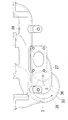
図1〜図6は本発明の第1実施形態、図7〜図8は第2実施形態に係るディーゼルエンジンの排気処理装置を説明する図であり、各実施形態では、多気筒ディーゼルエンジンの排気処理装置について説明する。 1 to 6 are diagrams illustrating an exhaust treatment device for a diesel engine according to a first embodiment of the present invention, and FIGS. 7 to 8 are diagrams illustrating an exhaust of a multi-cylinder diesel engine in each embodiment. The processing apparatus will be described.
第1実施形態の排気処理装置の概要は、次の通りである。
図1に示すように、排気経路(1)に排気分流器(2)を設け、排気分流器(2)で排気ガス(3)中のPMを偏在させ、排気ガス(3)を、偏在したPMを含むEGRガス(4)と残りの放出ガス(5)とに分流させ、EGRガス(4)を燃焼室(42)に還流させ、放出ガス(5)を大気側に放出するようにしている。
排気経路(1)は、排気ポート(43)、排気マニホルド(39)、排気ガス分流器(2)、過給機(40)の排気タービン(41)を順に接続して構成されている。EGRガス(4)は、EGRクーラ(44)、EGR弁室(45)、逆止弁室(46)を順に介して吸気経路(47)に還流される。吸気経路(47)は過給機(40)のコンプレッサ(48)、過給パイプ(56)、吸気マニホルド(49)、吸気ポート(50)を順に接続して構成されている。EGR弁室(45)のEGR弁(45a)は弁アクチュエータ(45b)で開閉駆動され、エンジン回転数やエンジン負荷に応じて、開閉され、その開度が調整される。
The outline of the exhaust treatment apparatus of the first embodiment is as follows.
As shown in FIG. 1, an exhaust gas diverter (2) is provided in the exhaust path (1), the PM in the exhaust gas (3) is unevenly distributed by the exhaust flow diverter (2), and the exhaust gas (3) is unevenly distributed. The EGR gas (4) containing PM is divided into the remaining release gas (5), the EGR gas (4) is returned to the combustion chamber (42), and the release gas (5) is released to the atmosphere side. Yes.
The exhaust path (1) is configured by sequentially connecting an exhaust port (43), an exhaust manifold (39), an exhaust gas diverter (2), and an exhaust turbine (41) of a supercharger (40). The EGR gas (4) is returned to the intake passage (47) through the EGR cooler (44), the EGR valve chamber (45), and the check valve chamber (46) in this order. The intake path (47) is configured by connecting a compressor (48), a supercharge pipe (56), an intake manifold (49), and an intake port (50) of the supercharger (40) in this order. The EGR valve (45a) in the EGR valve chamber (45) is driven to open and close by a valve actuator (45b), and is opened and closed according to the engine speed and engine load, and the opening degree is adjusted.
排気ガス分流器の構成は、次の通りである。
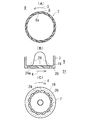
図2に示すように、排気ガス分流器(2)の中心部に中心筒(7)を配置し、この中心筒(7)の周壁に複数の放出ガス進入孔(8)を設け、この中心筒(7)の周囲に排気ガス旋回室(9)を設け、排気ガス分流器(2)に相互に異なる極性の電極(12)(13)を設け、これら電極(12)(13)間でのコロナ放電により、排気ガス(3)中のPMを所定の極性に帯電させるようになっている。
排気ガス旋回室(9)を周囲から取り囲む排気ガス旋回室周壁(14)を帯電PMと逆の極性の電極(13)にし、排気ガス旋回室(9)を旋回する排気ガス(3)中の帯電PMを遠心力と静電気力とで排気ガス旋回室周壁(14)寄りに偏在させ、偏在したPMを含む排気ガス(3)をEGRガス(4)として排気ガス旋回室終端部(15)に分流させるとともに、中心筒(7)寄りの排気ガス(3)を放出ガス(5)として放出ガス進入開口から中心筒(7)内に分流させる。
The configuration of the exhaust gas shunt is as follows.
As shown in FIG. 2, a central cylinder (7) is arranged at the center of the exhaust gas flow divider (2), and a plurality of discharge gas entry holes (8) are provided on the peripheral wall of the central cylinder (7). An exhaust gas swirl chamber (9) is provided around the cylinder (7), and electrodes (12) and (13) having different polarities are provided in the exhaust gas diverter (2). Between these electrodes (12) and (13), By this corona discharge, the PM in the exhaust gas (3) is charged to a predetermined polarity.
The exhaust gas swirl chamber peripheral wall (14) surrounding the exhaust gas swirl chamber (9) from the surroundings is made into an electrode (13) having a polarity opposite to that of the charged PM, The charged PM is unevenly distributed near the exhaust gas swirl chamber peripheral wall (14) by centrifugal force and electrostatic force, and the exhaust gas (3) containing the unevenly distributed PM is used as the EGR gas (4) in the exhaust gas swirl chamber end portion (15). At the same time, the exhaust gas (3) near the central cylinder (7) is diverted into the central cylinder (7) from the discharge gas entrance opening as the discharge gas (5).
この実施形態では、PMをマイナスの極性に帯電させる。そして、図2に示すように、中心筒(7)をPMと同じ極性のマイナスの電極(12)とする。
放出ガス進入開口を中心筒(7)の周壁に設けた複数個の放出ガス進入孔(8)(8)で構成している。
図2に示すように、中心筒(7)は円筒形で、放出ガス進入孔(8)は、中心筒(7)の母線に所定間隔を保持して一列に配置され、この列が中心筒(7)の周方向に所定間隔を保持して複数列配置されている。図4(A)に示すように、放出ガス進入孔(8)の開口縁に鋭角部(8a)を設けている。排気ガス旋回室(9)側から中心筒(7)内に向かう放出ガス進入孔(8)の向きを、排気ガス(3)の旋回方向と逆行する向きにしている。図4(A)に示すように、鋭角部(8a)は、中心軸(7)の中心軸直交断面図上、鋭角となっている部分である。この実施形態では、中心筒(7)を帯電PMと同じ極性の電極(12)とするので、帯電PMと異なる極性の電極(13)となる排気ガス旋回室周壁(14)との間で、コロナ放電が起こり、排気ガス旋回室(9)内で排気微粒子を効率的に帯電させることができる。
In this embodiment, PM is charged to a negative polarity. Then, as shown in FIG. 2, the central tube (7) is a negative electrode (12) having the same polarity as PM.
The release gas entry opening is constituted by a plurality of release gas entry holes (8) and (8) provided in the peripheral wall of the central cylinder (7).
As shown in FIG. 2, the central cylinder (7) has a cylindrical shape, and the discharge gas entry holes (8) are arranged in a line at a predetermined distance from the bus bar of the central cylinder (7). A plurality of rows are arranged at predetermined intervals in the circumferential direction of (7). As shown in FIG. 4 (A), an acute angle portion (8a) is provided at the opening edge of the released gas entry hole (8). The direction of the discharge gas entry hole (8) from the exhaust gas swirl chamber (9) side into the central cylinder (7) is set to be opposite to the swirl direction of the exhaust gas (3). As shown in FIG. 4A, the acute angle portion (8a) is a portion having an acute angle on the cross section of the central axis (7) perpendicular to the central axis. In this embodiment, since the central cylinder (7) is an electrode (12) having the same polarity as the charged PM, between the exhaust gas swirl chamber peripheral wall (14) serving as an electrode (13) having a polarity different from that of the charged PM, Corona discharge occurs, and the exhaust particulates can be charged efficiently in the exhaust gas swirl chamber (9).
図2、図3(A)に示すように、中心筒(7)を帯電PMと同じ極性の電極(12)とし、中心筒(7)の外周に排気ガス旋回室周壁(14)に向けて突出する放電用突起(6)を形成している。
図2に示すように、放電用突起(6)を帯電PMと同じ極性のマイナスの電極(12)としている。放電用突起(6)は中心筒(7)と一体成型されている。
As shown in FIGS. 2 and 3A, the central cylinder (7) is an electrode (12) having the same polarity as that of the charged PM, and the outer periphery of the central cylinder (7) is directed to the exhaust gas swirl chamber peripheral wall (14). A protruding discharge protrusion (6) is formed.
As shown in FIG. 2, the discharge protrusion (6) is a negative electrode (12) having the same polarity as the charged PM. The discharge protrusion (6) is integrally formed with the central tube (7).
図2、図3(A)に示すように、中心筒(7)の外周の周方向に沿って並べた放電用突起(6)の列を、中心筒(7)の軸長方向に複数列配置している。
図3(A)に示すように、中心筒(7)の外周の周方向に沿って並べた放電用突起(6)の列はノコ歯状に形成されている。図2に示すように、放電用突起(6)の列は、排気ガス旋回室始端部(10)で、最も上流側の放出ガス進入孔(8)の上流に3列隣接して配置されている。図2に示すように、複数個の放出ガス進入孔(8)(8)を中心筒(7)の軸長方向に沿って配置するに当たり、放電用突起(6)を軸長方向に並ぶ放出ガス進入孔(8)(8)の間に配置している。この放電用突起(6)は、隣合う放出ガス進入孔(8)(8)の間にある。
図2に示すように、放電用突起(6)の上流側に排気ガス偏向案内壁(18)を配置し、放電用突起(6)に向かう排気ガス(3)を排気ガス偏向案内壁(18)で放電用突起(6)の周囲の排気ガス旋回室周壁(14)側に偏向させるようにしている。この排気ガス偏向案内壁(18)の外周は下流に向かって次第に径大となる円錐台周面形状を内側に凹曲させた曲面形状である。
As shown in FIG. 2 and FIG. 3A, a plurality of rows of discharge protrusions (6) arranged along the circumferential direction of the outer periphery of the center tube (7) are arranged in the axial direction of the center tube (7). It is arranged.
As shown in FIG. 3A, the row of discharge protrusions (6) arranged along the circumferential direction of the outer periphery of the center tube (7) is formed in a sawtooth shape. As shown in FIG. 2, the discharge protrusions (6) are arranged at the exhaust gas swirl chamber start end (10), adjacent to the most upstream discharge gas inlet holes (8) and adjacent to the three rows. Yes. As shown in FIG. 2, when the plurality of discharge gas inlet holes (8) and (8) are arranged along the axial direction of the central cylinder (7), the discharge protrusions (6) are arranged in the axial direction. It arrange | positions between gas entrance holes (8) (8). This discharge projection (6) is located between adjacent discharge gas entry holes (8) and (8).
As shown in FIG. 2, an exhaust gas deflection guide wall (18) is disposed upstream of the discharge projection (6), and the exhaust gas (3) toward the discharge projection (6) is sent to the exhaust gas deflection guide wall (18). ) To the exhaust gas swirl chamber peripheral wall (14) side around the discharge projection (6). The outer periphery of the exhaust gas deflection guide wall (18) has a curved surface shape in which the shape of the frustoconical circumferential surface, which gradually increases in diameter toward the downstream, is bent inward.
図2に示すように、排気ガス旋回室終端部(15)に囲まれた中心筒終端部(19)に中心筒終端壁(20)を設け、排気ガス旋回室終端部(15)に隣接してEGRガス旋回室(21)を設け、EGRガス旋回室(21)を周囲から取り囲むEGRガス旋回室周壁(22)にEGRガス出口(23)を設け、中心筒終端壁(20)にガス抜き孔(24)をあけ、EGRガス旋回室(21)の中心部から溢れたEGRガス(4)のガス成分(25)がガス抜き孔(24)から放出ガス(5)として中心筒(7)内に流入するようにしている。 As shown in FIG. 2, a center tube end wall (20) is provided at the center tube end portion (19) surrounded by the exhaust gas swirl chamber end portion (15), and is adjacent to the exhaust gas swirl chamber end portion (15). The EGR gas swirl chamber (21) is provided, the EGR gas swirl chamber (21) is surrounded by the EGR gas swirl chamber peripheral wall (22), the EGR gas outlet (23) is provided, and the central cylinder end wall (20) is vented. A hole (24) is formed, and the gas component (25) of the EGR gas (4) overflowing from the center of the EGR gas swirl chamber (21) is discharged from the gas vent hole (24) as a discharge gas (5). It flows in.
図2に示すように、EGRガス旋回室周壁(22)とEGRガス旋回室端壁(22a)を帯電PMと異なる極性のプラスの電極(13)としている。また、中心筒終端壁(20)を帯電PMと同じ極性のマイナスの電極(12)としている。中心筒終端壁(20)は中心筒(7)の周壁と一体成型されている。 As shown in FIG. 2, the EGR gas swirl chamber peripheral wall (22) and the EGR gas swirl chamber end wall (22a) are positive electrodes (13) having a polarity different from that of the charged PM. Further, the central cylinder end wall (20) is a negative electrode (12) having the same polarity as the charged PM. The central cylinder end wall (20) is integrally formed with the peripheral wall of the central cylinder (7).
図4(B)に示すように、ガス抜き孔(24)の開口縁に鋭角部(24a)を設け、図4(B)(C)に示すように、EGRガス旋回室(21)の中心部側から中心筒(7)内に向かうガス抜き孔(24)の向きを、EGRガス(4)の旋回方向と逆行する向きにしている。図4(B)に示すように、鋭角部(24a)は、中心筒(7)の中心軸と平行でガス抜き孔(24)の中心軸を含む断面図上、鋭角となっている部分である。図2に示すように、中心筒(7)は上下方向に向けて配置され、中心筒終端壁(20)は中心筒(7)の下端部に配置され、図4(B)に示すように、ガス抜き孔(24)は中心筒(7)内からEGRガス旋回室(21)に向けて下り傾斜する向きとされ、エンジン停止中には、中心筒(7)内に溜まったPMが自重でガス抜き孔(24)からEGRガス旋回室(21)に流出するようにしてある。 As shown in FIG. 4 (B), an acute angle portion (24a) is provided at the opening edge of the gas vent hole (24), and as shown in FIGS. 4 (B) and (C), the center of the EGR gas swirl chamber (21) is provided. The direction of the gas vent hole (24) from the part side into the central cylinder (7) is set to be opposite to the turning direction of the EGR gas (4). As shown in FIG. 4 (B), the acute angle portion (24a) is a portion having an acute angle on the cross-sectional view including the central axis of the gas vent hole (24) parallel to the central axis of the central cylinder (7). is there. As shown in FIG. 2, the center tube (7) is arranged in the vertical direction, and the center tube end wall (20) is arranged at the lower end of the center tube (7), as shown in FIG. 4 (B). The gas vent hole (24) is inclined downward from the center tube (7) toward the EGR gas swirl chamber (21), and the PM accumulated in the center tube (7) is self-weighted when the engine is stopped. Then, the gas flows out from the vent hole (24) to the EGR gas swirl chamber (21).
図2に示すように、排気ガス旋回室(9)の上流に螺旋形の助走案内壁(26a)に沿う排気ガス旋回助走通路(26)を設けている。
図2に示すように、排気ガス旋回助走通路(26)で囲まれた排気ガス分流器(2)の中心部に放出ガス排出通路(27)を設け、この放出ガス排出通路(27)の排出通路入口(28)を中心筒始端部(29)にある中心筒出口(30)と連通させている。
図2に示すように、排気ガス旋回室周壁(14)と助走通路周壁(33)とを取り付けボルト(61)で連結している。
放出ガス排出通路(27)の排出通路周壁(27a)を、排出通路入口周壁(35)と、この排出通路入口周壁(35)よりも下流側の排出通路下流側周壁(36)とに区分し、排出通路下流側周壁(36)と中心筒出口周壁(37)との間に排出通路入口周壁(35)を介在させている。
As shown in FIG. 2, an exhaust gas swirl runway passage (26) is provided upstream of the exhaust gas swirl chamber (9) along the spiral runaway guide wall (26a).
As shown in FIG. 2, a discharge gas discharge passage (27) is provided at the center of the exhaust gas diverter (2) surrounded by the exhaust gas swirl run-up passage (26), and the discharge of the discharge gas discharge passage (27) is provided. The passage inlet (28) communicates with the central tube outlet (30) at the central tube start end (29).
As shown in FIG. 2, the exhaust gas swirl chamber peripheral wall (14) and the run-up passage peripheral wall (33) are connected by mounting bolts (61).
The discharge passage peripheral wall (27a) of the discharge gas discharge passage (27) is divided into a discharge passage inlet peripheral wall (35) and a discharge passage downstream peripheral wall (36) downstream of the discharge passage inlet peripheral wall (35). The discharge passage inlet peripheral wall (35) is interposed between the discharge passage downstream peripheral wall (36) and the central tube outlet peripheral wall (37).
排出通路入口周壁(35)を電気的絶縁体で成型し、中心筒(7)に対し、異なる極性の電極(13)となる排気ガス旋回室周壁(14)と助走通路周壁(33)と排出通路下流側周壁(36)とを電気的に絶縁している。
排出通路入口周壁(35)はアルミナで構成されている。
The discharge passage inlet peripheral wall (35) is molded from an electrical insulator, and the exhaust gas swirl chamber peripheral wall (14) and the run-up passage peripheral wall (33), which are electrodes (13) of different polarities, are discharged from the central tube (7). The passage downstream side peripheral wall (36) is electrically insulated.
The discharge passage inlet peripheral wall (35) is made of alumina.
図2に示すように、放電用突起(6)への入力端子(52)は、中心筒(7)を介して放電用突起(6)に接続されている。入力端子(52)と中心筒(7)は、入力端子(52)に嵌めた絶縁体のスペーサ(53)(54)で、EGRガス旋回室端壁(22a)と電気的に絶縁されている。中心筒(7)や放電用突起(6)等のマイナスの電極(12)への入力端子(52)は、導電板(62)を介して昇圧回路(58)のマイナス出力端子(58a)と接続されている。昇圧回路(58)のプラス出力はアース接続されている。プラスの電極(13)となる排気ガス旋回室周壁(14)とEGRガス旋回室周壁(22)とEGRガス旋回室端壁(22a)と助走通路周壁(33)と排出通路下流側周壁(36)と助走案内壁(26a)とは、エンジンの機体を介してアース(バッテリマイナス)に接続されている。図中の符号(55)はバッテリ、(58b)は昇圧回路(58)のプラス入力端子である。
スペーサ(53)(54)の接合部には入力端子(52)に嵌めた絶縁体の筒(66)を配置し、入力端子(52)とEGRガス旋回室端壁(22a)との間で放電が起こらないようにしている。
As shown in FIG. 2, the input terminal (52) to the discharge protrusion (6) is connected to the discharge protrusion (6) via the center tube (7). The input terminal (52) and the central cylinder (7) are electrically insulated from the end wall (22a) of the EGR gas swirl chamber by insulating spacers (53) (54) fitted to the input terminal (52). . The input terminal (52) to the negative electrode (12) such as the central tube (7) and the discharge protrusion (6) is connected to the negative output terminal (58a) of the booster circuit (58) via the conductive plate (62). It is connected. The positive output of the booster circuit (58) is grounded. An exhaust gas swirl chamber peripheral wall (14), an EGR gas swirl chamber peripheral wall (22), an EGR gas swirl chamber end wall (22a), a run-up passage peripheral wall (33), and a discharge passage downstream peripheral wall (36) serving as a positive electrode (13) ) And the run-up guide wall (26a) are connected to the ground (battery minus) via the engine body. In the figure, reference numeral (55) denotes a battery, and (58b) denotes a plus input terminal of the booster circuit (58).
An insulating tube (66) fitted to the input terminal (52) is disposed at the joint between the spacers (53) and (54), and between the input terminal (52) and the EGR gas swirl chamber end wall (22a). Discharge is prevented from occurring.
図2、図5、図6に示すように、助走通路周壁(33)と排出通路下流側周壁(36)と助走案内壁(26a)とを排気マニホルド(39)と一体成型している。これらは鋳鉄の一体鋳造品である。 As shown in FIGS. 2, 5, and 6, the auxiliary passage peripheral wall (33), the discharge passage downstream peripheral wall (36), and the auxiliary guide wall (26 a) are integrally formed with the exhaust manifold (39). These are integrally cast products of cast iron.
図1に示すように、過給機(40)の排気タービン(41)よりも上流に排気ガス分流器(2)を設けている。また、排気ガス(3)中のPMを捕捉し、PMを燃焼除去して再生する、DPFを用いることなく、放出ガス(5)を大気側に排出するようになっている。 As shown in FIG. 1, an exhaust gas diverter (2) is provided upstream of the exhaust turbine (41) of the supercharger (40). Further, the exhaust gas (3) is trapped, and the emitted gas (5) is discharged to the atmosphere without using the DPF, which is recovered by burning and removing the PM.
図2、図3(A)に示すように、排気分流器(2)の端部に回路収容ケース(57)を設け、この回路収容ケース(57)に昇圧回路(58)を収容し、この昇圧回路(58)で昇圧した電圧を排気分流器(2)の電極(12)(13)に印加するようにしている。
昇圧回路(58)と電気的に接続した導電体(59)を排気分流器(2)の端壁(60)に貫通させ、この導電体(59)を介して昇圧回路(58)で昇圧した電圧を排気分流器(2)の電極(12)(13)に印加するようにしている。
導電体(59)は入力端子(52)であり、この入力端子(52)は導電板(62)を介して昇圧回路(58)のマイナス出力端子(58a)に電気的に接続されている。
回路収容ケース(57)は環状で、中心部に入力端子(52)と導電板(62)とが配置され、その周囲のケース内に昇圧回路(58)が収容され、導電板(62)は入力端子(52)に嵌めた絶縁体のスペーサ(54)と導電体の座金(63)の間に挟み付けて固定され、入力端子(52)に電気的に接続されている。昇圧回路(58)の上側には回路収容ケース(57)の断熱空気室(64)が配置されている。
As shown in FIGS. 2 and 3A, a circuit housing case (57) is provided at the end of the exhaust flow divider (2), and a booster circuit (58) is housed in the circuit housing case (57). The voltage boosted by the booster circuit (58) is applied to the electrodes (12) and (13) of the exhaust shunt (2).
A conductor (59) electrically connected to the booster circuit (58) is passed through the end wall (60) of the exhaust shunt (2), and the voltage is boosted by the booster circuit (58) through this conductor (59). A voltage is applied to the electrodes (12) and (13) of the exhaust gas shunt (2).
The conductor (59) is an input terminal (52), and the input terminal (52) is electrically connected to the negative output terminal (58a) of the booster circuit (58) through the conductive plate (62).
The circuit housing case (57) is annular, and the input terminal (52) and the conductive plate (62) are arranged at the center, the booster circuit (58) is housed in the surrounding case, and the conductive plate (62) The insulating spacer (54) fitted to the input terminal (52) is fixed by being sandwiched between a conductive washer (63) and electrically connected to the input terminal (52). An insulated air chamber (64) of the circuit housing case (57) is disposed above the booster circuit (58).
図7〜図8に示す本発明の第2実施形態は、第1実施形態と次の点で異なる。
排気ガス旋回室始端部(10)に排気ガス旋回案内羽根(11)を設け、この排気ガス旋回案内羽根(11)を帯電PMと同じ極性の電極(12)とし、排気ガス旋回案内羽根(11)の縁部(16)(17)に鋭角部(16a)(17a)を設けている。
このため、排気ガス旋回案内羽根(11)の整流作用により、排気ガス旋回室(9)での排気ガス(3)の旋回速度を高めることができ、排気ガス(3)中のPMにかかる遠心力を大きくし、EGRガス(4)のPM濃度を高めることができる。
また、異なる極性の電極(13)となる排気ガス旋回室周壁(14)との間で、コロナ放電が起こり、排気ガス旋回室(9)内で排気微粒子を効率的に帯電させることができる。
また、排気ガス(3)中のPMを効率的に帯電させることができる。その理由は、鋭角部(16a)(17a)付近に電界の集中箇所が発生し、コロナ放電が生起することによってPMに効率的に電荷を付与するためと推定される。
The second embodiment of the present invention shown in FIGS. 7 to 8 differs from the first embodiment in the following points.
An exhaust gas swirl guide vane (11) is provided at the exhaust gas swirl chamber start end (10), and this exhaust gas swirl guide vane (11) is used as an electrode (12) having the same polarity as the charged PM. ) Edge portions (16) and (17) are provided with acute angle portions (16a) and (17a).
Therefore, the swirl speed of the exhaust gas (3) in the exhaust gas swirl chamber (9) can be increased by the rectifying action of the exhaust gas swirl guide vane (11), and the centrifugal force applied to the PM in the exhaust gas (3). The force can be increased and the PM concentration of the EGR gas (4) can be increased.
Further, corona discharge occurs between the exhaust gas swirl chamber peripheral wall (14) serving as the electrodes (13) of different polarities, and the exhaust particulates can be efficiently charged in the exhaust gas swirl chamber (9).
Moreover, PM in exhaust gas (3) can be charged efficiently. The reason for this is presumed to be that the electric field is concentrated near the acute angle portions (16a) and (17a) and corona discharge is generated to efficiently charge the PM.
排気ガス旋回室始端部(10)に排気ガス旋回案内羽根(11)を設け、この排気ガス旋回案内羽根(11)と、排気ガス旋回助走通路(26)を周囲から取り囲む助走通路周壁(33)とを、相互に異なる極性の電極(12)(13)としている。
排気ガス旋回案内羽根(11)はマイナスの電極(12)、助走通路周壁(33)はプラスの電極(13)である。
An exhaust gas swirl guide vane (11) is provided at the start end (10) of the exhaust gas swirl chamber, and the peripheral wall (33) of the runway surrounding the exhaust gas swirl guide vane (11) and the exhaust gas swirl runway (26) from the surroundings. Are
The exhaust gas swirl guide vane (11) is a negative electrode (12), and the runway peripheral wall (33) is a positive electrode (13).
中心筒出口周壁(37)の周囲に排気ガス旋回室始端部(10)を設け、排気ガス旋回室周壁(14)を、排気ガス旋回室始端部(10)を周囲から取り囲む旋回室始端部周壁(31)と、この旋回室始端部周壁(31)よりも下流側の旋回室下流側周壁(32)とに区分し、助走通路周壁(33)と旋回室下流側周壁(32)との間に旋回室始端部周壁(31)を介在させている。
放出ガス排出通路(27)の排出通路周壁(27a)を、排出通路入口周壁(35)と、この排出通路入口周壁(35)よりも下流側の排出通路下流側周壁(36)とに区分し、排出通路下流側周壁(36)と中心筒出口周壁(37)との間に排出通路入口周壁(35)を介在させ、旋回室始端部周壁(31)と排出通路入口周壁(35)とこれらを連結する架橋体(31a)とを電気的絶縁体で一体成型し、排気ガス旋回案内羽根(11)と同じ極性の電極(12)となる中心筒(7)に対し、排気ガス旋回案内羽根(11)と異なる極性の電極(13)となる旋回室下流側周壁(32)と助走通路周壁(33)と排出通路下流側周壁(36)とを電気的に絶縁している。
また、この絶縁体は、中心筒(7)に対し、異なる極性の電極(13)となるEGRガス旋回室周壁(22)とEGRガス旋回室端壁(22a)も電気的に絶縁している。絶縁体はアルミナで構成されている。
絶縁部品の組み付けは一括して行うことができる。
An exhaust gas swirl chamber start end (10) is provided around the central cylinder outlet peripheral wall (37), and the exhaust gas swirl chamber peripheral wall (14) surrounds the exhaust gas swirl chamber start end (10) from the periphery. (31) and a swirl chamber downstream peripheral wall (32) downstream of the swirl chamber start end peripheral wall (31), and between the runway peripheral wall (33) and the swirl chamber downstream peripheral wall (32). The swirl chamber start end peripheral wall (31) is interposed between the two.
The discharge passage peripheral wall (27a) of the discharge gas discharge passage (27) is divided into a discharge passage inlet peripheral wall (35) and a discharge passage downstream peripheral wall (36) downstream of the discharge passage inlet peripheral wall (35). The discharge passage inlet peripheral wall (35) is interposed between the discharge passage downstream peripheral wall (36) and the central tube outlet peripheral wall (37), and the swirl chamber start end peripheral wall (31), the discharge passage inlet peripheral wall (35), and these The cross-linking body (31a) connecting the two is integrally molded with an electrical insulator, and the exhaust gas swirl guide vane is placed against the central cylinder (7) serving as the electrode (12) having the same polarity as the exhaust gas swirl guide vane (11). The swirl chamber downstream peripheral wall (32), the run-up passage peripheral wall (33), and the discharge passage downstream peripheral wall (36), which are electrodes (13) having a polarity different from (11), are electrically insulated.
In addition, this insulator also electrically insulates the EGR gas swirl chamber peripheral wall (22) and the EGR gas swirl chamber end wall (22a), which are electrodes (13) of different polarities, from the central tube (7). . The insulator is made of alumina.
Insulating parts can be assembled together.
架橋体(31a)を排気ガス旋回案内羽根(11)の上流に位置する上流排気ガス旋回案内羽根(38)とした。このため、上流排気ガス旋回案内羽根(38)の整流作用により、排気ガス旋回室(9)での排気ガス(3)の旋回速度を高めることができ、排気ガス(3)中のPMにかかる遠心力を大きくし、EGRガス(4)のPM濃度を高めることができる。
第2実施形態の他の構成や機能は、第1実施形態と同じであり、図7〜図8中、第1実施形態と同一の要素には、同一の符号を付しておく。
The bridged body (31a) was an upstream exhaust gas swirl guide vane (38) located upstream of the exhaust gas swirl guide blade (11). Therefore, the swirling speed of the exhaust gas (3) in the exhaust gas swirl chamber (9) can be increased by the rectifying action of the upstream exhaust gas swirl guide vane (38), and the PM in the exhaust gas (3) is applied. Centrifugal force can be increased and the PM concentration of EGR gas (4) can be increased.
Other configurations and functions of the second embodiment are the same as those of the first embodiment. In FIGS. 7 to 8, the same elements as those of the first embodiment are denoted by the same reference numerals.
本発明の実施形態は、以上の通りであるが、本発明は上記実施形態に限定させるものではなく、PMをプラスの極性に帯電させるものであってもよく、この場合には、中心筒(7)や排気ガス旋回案内羽根(11)を帯電PMと同じ極性のプラスの電極とし、旋回室下流側周壁(32)とEGRガス旋回室周壁(22)とEGRガス旋回室端壁(22a)と助走通路周壁(33)と排出通路下流側周壁(36)と助走案内羽根(26a)とを帯電PMと異なる極性のマイナスの電極とする。 The embodiment of the present invention is as described above, but the present invention is not limited to the above-described embodiment, and the PM may be charged to a positive polarity. 7) or the exhaust gas swirl guide vane (11) as a positive electrode having the same polarity as the charged PM, the swirl chamber downstream peripheral wall (32), the EGR gas swirl chamber peripheral wall (22), and the EGR gas swirl chamber end wall (22a) The peripheral wall (33) of the run-up passage, the peripheral wall (36) on the downstream side of the discharge passage, and the run-up guide vane (26a) are negative electrodes having a polarity different from that of the charged PM.
(1) 排気経路
(2) 排気ガス分流器
(3) 排気ガス
(4) EGRガス
(5) 放出ガス
(6) 放電用突起
(7) 中心筒
(8) 放出ガス進入孔
(8a) 鋭角部
(9) 排気ガス旋回室
(12) 電極
(13) 電極
(14) 排気ガス旋回室周壁
(15) 排気ガス旋回室終端部
(18) 排気ガス偏向案内壁
(19) 中心筒終端部
(20) 中心筒終端壁
(21) EGRガス旋回室
(22) EGRガス旋回室周壁
(23) EGRガス出口
(24) ガス抜き孔
(24a) 鋭角部
(25)ガス成分
(26) 排気ガス旋回助走通路
(26a) 助走案内壁
(27) 放出ガス排出通路
(27a) 排出通路周壁
(28) 排出通路入口
(29) 中心筒始端部
(30) 中心筒出口
(33) 助走通路周壁
(35) 排出通路入口周壁
(36) 排出通路下流側周壁
(37) 中心筒出口周壁
(39) 排気マニホルド
(40) 過給機
(41) 排気タービン
(57) 回路収容ケース
(58) 昇圧回路
(59) 導電体
(60) 端壁
(1) Exhaust route
(2) Exhaust gas shunt
(3) Exhaust gas
(4) EGR gas
(5) Emission gas
(6) Discharge protrusion
(7) Center tube
(8) Released gas entry hole
(8a) Sharp corner
(9) Exhaust gas swirl chamber
(12) Electrode
(13) Electrode
(14) Exhaust gas swirl chamber peripheral wall
(15) Exhaust gas swirl chamber end
(18) Exhaust gas deflection guide wall
(19) Central tube end
(20) Central cylinder end wall
(21) EGR gas swirl chamber
(22) EGR gas swirl chamber peripheral wall
(23) EGR gas outlet
(24) Gas vent hole
(24a) Sharp corner
(25) Gas component
(26) Exhaust gas turning approach passage
(26a) Run-up guide wall
(27) Emission gas discharge passage
(27a) Outlet passage wall
(28) Discharge passage entrance
(29) Center tube start end
(30) Center tube exit
(33) Runway wall
(35) Discharge passage entrance peripheral wall
(36) Outlet passage downstream peripheral wall
(37) Center tube outlet peripheral wall
(39) Exhaust manifold
(40) Turbocharger
(41) Exhaust turbine
(57) Circuit housing case
(58) Booster circuit
(59) Conductor
(60) End wall
Claims (22)
排気ガス分流器(2)の中心部に中心筒(7)を配置し、この中心筒(7)に放出ガス進入開口を設け、この中心筒(7)の周囲に排気ガス旋回室(9)を設け、排気ガス分流器(2)に相互に異なる極性の電極(12)(13)を設け、これら電極(12)(13)間でのコロナ放電により、排気ガス(3)中のPMを所定の極性に帯電させ、
排気ガス旋回室(9)を周囲から取り囲む排気ガス旋回室周壁(14)を帯電PMと逆の極性の電極(13)にし、
排気ガス旋回室(9)を旋回する排気ガス(3)中の帯電PMを遠心力と静電気力とで排気ガス旋回室周壁(14)寄りに偏在させ、偏在したPMを含む排気ガス(3)をEGRガス(4)として排気ガス旋回室終端部(15)に分流させるとともに、中心筒(7)寄りの排気ガス(3)を放出ガス(5)として放出ガス進入開口から中心筒(7)内に分流させ、
排気ガス旋回室(9)の上流に螺旋形の助走案内壁(26a)に沿う排気ガス旋回助走通路(26)を設け、
中心筒(7)と、排気ガス旋回助走通路(26)を周囲から取り囲む助走通路周壁(33)とを、相互に異なる極性の電極(12)(13)とし、
放出ガス排出通路(27)の排出通路周壁(27a)を、排出通路入口周壁(35)と、この排出通路入口周壁(35)よりも下流側の排出通路下流側周壁(36)とに区分し、排出通路下流側周壁(36)と中心筒出口周壁(37)との間に排出通路入口周壁(35)を介在させ、
排出通路入口周壁(35)を電気的絶縁体で成型し、
中心筒(7)に対し、異なる極性の電極(13)となる排気ガス旋回室周壁(14)と助走通路周壁(33)と排出通路下流側周壁(36)とを電気的に絶縁した、ことを特徴とするディーゼルエンジンの排気処理装置。 An exhaust gas diverter (2) is provided in the exhaust path (1), PM in the exhaust gas (3) is unevenly distributed by the exhaust flow diverter (2), and the exhaust gas (3) is converted into EGR gas (4 ) And the remaining emission gas (5), the EGR gas (4) is recirculated to the combustion chamber (42), and the emission gas (5) is released to the atmosphere side. In
A central cylinder (7) is arranged at the center of the exhaust gas diverter (2), a discharge gas entrance opening is provided in the central cylinder (7), and an exhaust gas swirl chamber (9) is provided around the central cylinder (7). The exhaust gas diverter (2) is provided with electrodes (12) and (13) having different polarities, and the PM in the exhaust gas (3) is removed by corona discharge between the electrodes (12) and (13). Electrified to a predetermined polarity,
The exhaust gas swirl chamber peripheral wall (14) surrounding the exhaust gas swirl chamber (9) from the surroundings is made into an electrode (13) having a polarity opposite to that of the charged PM,
The charged PM in the exhaust gas (3) swirling in the exhaust gas swirl chamber (9) is unevenly distributed near the peripheral wall (14) of the exhaust gas swirl chamber by centrifugal force and electrostatic force, and the exhaust gas (3) containing the unevenly distributed PM Is divided into the exhaust gas swirl chamber end portion (15) as EGR gas (4), and the exhaust gas (3) near the central tube (7) is discharged as gas (5) from the discharge gas entrance opening to the central tube (7). Shunt in,
An exhaust gas swirl run-up passage (26) along the spiral run-up guide wall (26a) is provided upstream of the exhaust gas swirl chamber (9) ,
The center tube (7) and the surrounding wall (33) of the approaching passage surrounding the exhaust gas swirling approaching passage (26) from the surroundings are electrodes (12) and (13) having different polarities ,
The discharge passage peripheral wall (27a) of the discharge gas discharge passage (27) is divided into a discharge passage inlet peripheral wall (35) and a discharge passage downstream peripheral wall (36) downstream of the discharge passage inlet peripheral wall (35). The discharge passage inlet peripheral wall (35) is interposed between the discharge passage downstream peripheral wall (36) and the central tube outlet peripheral wall (37),
Molding the discharge passage inlet peripheral wall (35) with an electrical insulator,
The central wall (7) is electrically insulated from the exhaust gas swirl chamber peripheral wall (14), the auxiliary passage peripheral wall (33), and the discharge passage downstream peripheral wall (36), which are electrodes (13) of different polarities. An exhaust treatment device for diesel engines.
中心筒(7)を帯電PMと同じ極性の電極(12)とし、中心筒(7)の外周に排気ガス旋回室周壁(14)に向けて突出する放電用突起(6)を形成するに当たり、
排出通路入口周壁(35)を排気ガス偏向案内壁(18)とし、放電用突起(6)に向かう排気ガス(3)を排気ガス偏向案内壁(18)で放電用突起(6)の周囲の排気ガス旋回室周壁(14)側に偏向させるようにした、ことを特徴とするディーゼルエンジンの排気処理装置。 In the exhaust treatment device of the diesel engine according to claim 1 ,
When the central cylinder (7) is an electrode (12) having the same polarity as the charged PM and the discharge protrusion (6) protruding toward the exhaust gas swirl chamber peripheral wall (14) is formed on the outer periphery of the central cylinder (7),
The discharge passage inlet peripheral wall (35) is an exhaust gas deflection guide wall (18), and the exhaust gas (3) toward the discharge projection (6) is surrounded by the exhaust gas deflection guide wall (18) around the discharge projection (6). An exhaust treatment device for a diesel engine, characterized by being deflected toward the exhaust gas swirl chamber peripheral wall (14) side.
助走通路周壁(33)と排出通路下流側周壁(36)とを排気マニホルド(39)と一体成型した、ことを特徴とするディーゼルエンジンの排気処理装置。 In the exhaust treatment device for a diesel engine according to claim 1 or 2 ,
An exhaust treatment device for a diesel engine, characterized in that an auxiliary passage peripheral wall (33) and a discharge passage downstream peripheral wall (36) are integrally formed with an exhaust manifold (39).
排気ガス旋回助走通路(26)で囲まれた排気ガス分流器(2)の中心部に放出ガス排出通路(27)を設け、この放出ガス排出通路(27)の排出通路入口(28)を中心筒始端部(29)にある中心筒出口(30)と連通させた、ことを特徴とするディーゼルエンジンの排気処理装置。 In the exhaust treatment device of the diesel engine according to any one of claims 1 to 3 ,
A discharge gas discharge passage (27) is provided at the center of the exhaust gas diverter (2) surrounded by the exhaust gas swirl run-up passage (26), and the discharge passage inlet (28) of the discharge gas discharge passage (27) is centered. An exhaust treatment apparatus for a diesel engine, characterized in that it communicates with a central cylinder outlet (30) at a cylinder start end (29).
放出ガス進入開口を中心筒(7)の周壁に設けた複数個の放出ガス進入孔(8)(8)で構成した、ことを特徴とするディーゼルエンジンの排気処理装置。 In the exhaust treatment device of the diesel engine according to any one of claims 1 to 4 ,
An exhaust gas treatment apparatus for a diesel engine, characterized in that the discharge gas entry opening is constituted by a plurality of discharge gas entry holes (8) and (8) provided in the peripheral wall of the central cylinder (7).
中心筒(7)を帯電PMと同じ極性の電極(12)とし、中心筒(7)の外周に排気ガス旋回室周壁(14)に向けて突出する放電用突起(6)を形成し、The center tube (7) is an electrode (12) having the same polarity as the charged PM, and a discharge projection (6) is formed on the outer periphery of the center tube (7) and projects toward the exhaust gas swirl chamber peripheral wall (14).
放出ガス進入開口を中心筒(7)の周壁に設けた複数個の放出ガス進入孔(8)(8)で構成し、 The discharge gas entrance opening is constituted by a plurality of discharge gas entry holes (8) and (8) provided in the peripheral wall of the central cylinder (7).
複数個の放出ガス進入孔(8)(8)を中心筒(7)の軸長方向に沿って配置するに当たり、 In arranging a plurality of discharge gas entrance holes (8), (8) along the axial length direction of the central cylinder (7),
放電用突起(6)を軸長方向に並ぶ放出ガス進入孔(8)(8)の間に配置した、ことを特徴とするディーゼルエンジンの排気処理装置。 An exhaust treatment apparatus for a diesel engine, characterized in that the discharge protrusions (6) are arranged between the discharge gas entry holes (8), (8) arranged in the axial direction.
排気ガス分流器(2)の中心部に中心筒(7)を配置し、この中心筒(7)に放出ガス進入開口を設け、この中心筒(7)の周囲に排気ガス旋回室(9)を設け、排気ガス分流器(2)に相互に異なる極性の電極(12)(13)を設け、これら電極(12)(13)間でのコロナ放電により、排気ガス(3)中のPMを所定の極性に帯電させ、
排気ガス旋回室(9)を周囲から取り囲む排気ガス旋回室周壁(14)を帯電PMと逆の極性の電極(13)にし、
排気ガス旋回室(9)を旋回する排気ガス(3)中の帯電PMを遠心力と静電気力とで排気ガス旋回室周壁(14)寄りに偏在させ、偏在したPMを含む排気ガス(3)をEGRガス(4)として排気ガス旋回室終端部(15)に分流させるとともに、中心筒(7)寄りの排気ガス(3)を放出ガス(5)として放出ガス進入開口から中心筒(7)内に分流させ、
放出ガス進入開口を中心筒(7)の周壁に設けた複数個の放出ガス進入孔(8)(8)で構成し、
中心筒(7)を帯電PMと同じ極性の電極(12)とし、中心筒(7)の外周に排気ガス旋回室周壁(14)に向けて突出する放電用突起(6)を形成し、
放出ガス進入開口を中心筒(7)の周壁に設けた複数個の放出ガス進入孔(8)(8)で構成し、
複数個の放出ガス進入孔(8)(8)を中心筒(7)の軸長方向に沿って配置するに当たり、
放電用突起(6)を軸長方向に並ぶ放出ガス進入孔(8)(8)の間に配置した、ことを特徴とするディーゼルエンジンの排気処理装置。 An exhaust gas diverter (2) is provided in the exhaust path (1), PM in the exhaust gas (3) is unevenly distributed by the exhaust flow diverter (2), and the exhaust gas (3) is converted into EGR gas (4 ) And the remaining emission gas (5), the EGR gas (4) is recirculated to the combustion chamber (42), and the emission gas (5) is released to the atmosphere side. In
A central cylinder (7) is arranged at the center of the exhaust gas diverter (2), a discharge gas entrance opening is provided in the central cylinder (7), and an exhaust gas swirl chamber (9) is provided around the central cylinder (7). The exhaust gas diverter (2) is provided with electrodes (12) and (13) having different polarities, and the PM in the exhaust gas (3) is removed by corona discharge between the electrodes (12) and (13). Electrified to a predetermined polarity,
The exhaust gas swirl chamber peripheral wall (14) surrounding the exhaust gas swirl chamber (9) from the surroundings is made into an electrode (13) having a polarity opposite to that of the charged PM,
The charged PM in the exhaust gas (3) swirling in the exhaust gas swirl chamber (9) is unevenly distributed near the peripheral wall (14) of the exhaust gas swirl chamber by centrifugal force and electrostatic force, and the exhaust gas (3) containing the unevenly distributed PM Is divided into the exhaust gas swirl chamber end portion (15) as EGR gas (4), and the exhaust gas (3) near the central tube (7) is discharged as gas (5) from the discharge gas entrance opening to the central tube (7). Shunt in,
The discharge gas entrance opening is constituted by a plurality of discharge gas entry holes (8) and (8) provided in the peripheral wall of the central cylinder (7) .
The center tube (7) is an electrode (12) having the same polarity as the charged PM, and a discharge projection (6) is formed on the outer periphery of the center tube (7) and projects toward the exhaust gas swirl chamber peripheral wall (14).
The discharge gas entrance opening is constituted by a plurality of discharge gas entry holes (8) and (8) provided in the peripheral wall of the central cylinder (7).
In arranging a plurality of discharge gas entrance holes (8), (8) along the axial length direction of the central cylinder (7),
An exhaust treatment apparatus for a diesel engine, characterized in that the discharge protrusions (6) are arranged between the discharge gas entry holes (8), (8) arranged in the axial direction.
放電用突起(6)の上流側に排気ガス偏向案内壁(18)を配置し、放電用突起(6)に向かう排気ガス(3)を排気ガス偏向案内壁(18)で放電用突起(6)の周囲の排気ガス旋回室周壁(14)側に偏向させるようにした、ことを特徴とするディーゼルエンジンの排気処理装置。 In the exhaust treatment device for a diesel engine according to claim 6 or 7 ,
An exhaust gas deflection guide wall (18) is disposed upstream of the discharge projection (6), and the exhaust gas (3) toward the discharge projection (6) is discharged to the discharge projection (6) by the exhaust gas deflection guide wall (18). ) Around the exhaust gas swirl chamber peripheral wall (14) side.
放出ガス進入孔(8)の開口縁に鋭角部(8a)を設けた、ことを特徴とするディーゼルエンジンの排気処理装置。 In the exhaust treatment device for a diesel engine according to any one of claims 5 to 8 ,
An exhaust treatment apparatus for a diesel engine, characterized in that an acute angle portion (8a) is provided at an opening edge of the discharge gas entry hole (8).
排気ガス旋回室(9)側から中心筒(7)内に向かう放出ガス進入孔(8)の向きを、排気ガス(3)の旋回方向と逆行する向きにした、ことを特徴とするディーゼルエンジンの排気処理装置。 In the exhaust treatment device for a diesel engine according to any one of claims 5 to 9 ,
Diesel engine characterized in that the direction of the discharge gas entry hole (8) from the exhaust gas swirl chamber (9) side into the central cylinder (7) is opposite to the swirl direction of the exhaust gas (3) Exhaust treatment equipment.
排気ガス旋回室終端部(15)に囲まれた中心筒終端部(19)に中心筒終端壁(20)を設け、排気ガス旋回室終端部(15)に隣接してEGRガス旋回室(21)を設け、EGRガス旋回室(21)を周囲から取り囲むEGRガス旋回室周壁(22)にEGRガス出口(23)を設け、中心筒終端壁(20)にガス抜き孔(24)をあけ、 A center tube end wall (20) is provided at the center tube end portion (19) surrounded by the exhaust gas swirl chamber end portion (15), and the EGR gas swirl chamber (21 is adjacent to the exhaust gas swirl chamber end portion (15). ), EGR gas swirl chamber peripheral wall (22) surrounding EGR gas swirl chamber (21) from the surroundings, EGR gas outlet (23) is provided, and central cylinder end wall (20) has a vent hole (24),
EGRガス旋回室(21)の中心部から溢れたEGRガス(4)のガス成分(25)が放出ガス(5)としてガス抜き孔(24)から中心筒(7)内に流入するようにした、ことを特徴とするディーゼルエンジンの排気処理装置。 The gas component (25) of the EGR gas (4) overflowing from the center of the EGR gas swirl chamber (21) flows into the central cylinder (7) from the gas vent hole (24) as a discharge gas (5). An exhaust treatment device for a diesel engine, characterized by that.
排気ガス分流器(2)の中心部に中心筒(7)を配置し、この中心筒(7)に放出ガス進入開口を設け、この中心筒(7)の周囲に排気ガス旋回室(9)を設け、排気ガス分流器(2)に相互に異なる極性の電極(12)(13)を設け、これら電極(12)(13)間でのコロナ放電により、排気ガス(3)中のPMを所定の極性に帯電させ、
排気ガス旋回室(9)を周囲から取り囲む排気ガス旋回室周壁(14)を帯電PMと逆の極性の電極(13)にし、
排気ガス旋回室(9)を旋回する排気ガス(3)中の帯電PMを遠心力と静電気力とで排気ガス旋回室周壁(14)寄りに偏在させ、偏在したPMを含む排気ガス(3)をEGRガス(4)として排気ガス旋回室終端部(15)に分流させるとともに、中心筒(7)寄りの排気ガス(3)を放出ガス(5)として放出ガス進入開口から中心筒(7)内に分流させ、
排気ガス旋回室終端部(15)に囲まれた中心筒終端部(19)に中心筒終端壁(20)を設け、排気ガス旋回室終端部(15)に隣接してEGRガス旋回室(21)を設け、EGRガス旋回室(21)を周囲から取り囲むEGRガス旋回室周壁(22)にEGRガス出口(23)を設け、中心筒終端壁(20)にガス抜き孔(24)をあけ、
EGRガス旋回室(21)の中心部から溢れたEGRガス(4)のガス成分(25)が放出ガス(5)としてガス抜き孔(24)から中心筒(7)内に流入するようにした、ことを特徴とするディーゼルエンジンの排気処理装置。 An exhaust gas diverter (2) is provided in the exhaust path (1), PM in the exhaust gas (3) is unevenly distributed by the exhaust flow diverter (2), and the exhaust gas (3) is converted into EGR gas (4 ) And the remaining emission gas (5), the EGR gas (4) is recirculated to the combustion chamber (42), and the emission gas (5) is released to the atmosphere side. In
A central cylinder (7) is arranged at the center of the exhaust gas diverter (2), a discharge gas entrance opening is provided in the central cylinder (7), and an exhaust gas swirl chamber (9) is provided around the central cylinder (7). The exhaust gas diverter (2) is provided with electrodes (12) and (13) having different polarities, and the PM in the exhaust gas (3) is removed by corona discharge between the electrodes (12) and (13). Electrified to a predetermined polarity,
The exhaust gas swirl chamber peripheral wall (14) surrounding the exhaust gas swirl chamber (9) from the surroundings is made into an electrode (13) having a polarity opposite to that of the charged PM,
The charged PM in the exhaust gas (3) swirling in the exhaust gas swirl chamber (9) is unevenly distributed near the peripheral wall (14) of the exhaust gas swirl chamber by centrifugal force and electrostatic force, and the exhaust gas (3) containing the unevenly distributed PM Is divided into the exhaust gas swirl chamber end portion (15) as EGR gas (4), and the exhaust gas (3) near the central tube (7) is discharged as gas (5) from the discharge gas entrance opening to the central tube (7). Shunt in,
A center tube end wall (20) is provided at the center tube end portion (19) surrounded by the exhaust gas swirl chamber end portion (15), and the EGR gas swirl chamber (21 is adjacent to the exhaust gas swirl chamber end portion (15). ), EGR gas swirl chamber peripheral wall (22) surrounding EGR gas swirl chamber (21) from the surroundings, EGR gas outlet (23) is provided, and central cylinder end wall (20) has a vent hole (24),
The gas component (25) of the EGR gas (4) overflowing from the center of the EGR gas swirl chamber (21) flows into the central cylinder (7) from the gas vent hole (24) as a discharge gas (5). An exhaust treatment device for a diesel engine, characterized by that.
EGRガス旋回室周壁(22)を帯電PMと異なる極性の電極(13)とした、ことを特徴とするディーゼルエンジンの排気処理装置。 In the exhaust treatment device for a diesel engine according to claim 11 or 12 ,
An exhaust treatment apparatus for a diesel engine, characterized in that the EGR gas swirl chamber peripheral wall (22) is an electrode (13) having a polarity different from that of the charged PM.
中心筒終端壁(20)を帯電PMと同じ極性の電極(12)とした、ことを特徴とするディーゼルエンジンの排気処理装置。 The exhaust gas treatment apparatus for a diesel engine according to claim 13 ,
An exhaust treatment apparatus for a diesel engine, characterized in that the central cylinder end wall (20) is an electrode (12) having the same polarity as the charged PM.
ガス抜き孔(24)の開口縁に鋭角部(24a)を設けた、ことを特徴とするディーゼルエンジンの排気処理装置。 The exhaust gas treatment apparatus for a diesel engine according to claim 14 ,
An exhaust treatment apparatus for a diesel engine, characterized in that an acute angle portion (24a) is provided at an opening edge of the gas vent hole (24).
EGRガス旋回室(21)の中心部側から中心筒(7)内に向かうガス抜き孔(24)の向きを、EGRガス(4)の旋回方向と逆行する向きにした、ことを特徴とするディーゼルエンジンの排気処理装置。 In the exhaust treatment device for a diesel engine according to any one of claims 11 to 15 ,
The direction of the gas vent hole (24) from the center side of the EGR gas swirl chamber (21) into the central cylinder (7) is set to be opposite to the swirl direction of the EGR gas (4). Diesel engine exhaust treatment equipment.
中心筒(7)を帯電PMと同じ極性の電極(12)とした、ことを特徴とするディーゼルエンジンの排気処理装置。 The exhaust treatment apparatus for a diesel engine according to any one of claims 1 to 16 ,
An exhaust treatment apparatus for a diesel engine, characterized in that the central cylinder (7) is an electrode (12) having the same polarity as the charged PM.
排気ガス(3)中のPMを捕捉し、PMを燃焼除去して再生する、DPFを用いることなく、放出ガス(5)を大気側に排出するようにした、ことを特徴とするディーゼルエンジンの排気処理装置。 The exhaust treatment apparatus for a diesel engine according to any one of claims 1 to 17 ,
A diesel engine that captures PM in exhaust gas (3), burns and removes PM, and regenerates the exhaust gas (5) to the atmosphere without using DPF. Exhaust treatment device.
中心筒(7)を帯電PMと同じ極性の電極(12)とし、中心筒(7)の外周に排気ガス旋回室周壁(14)に向けて突出する放電用突起(6)を形成した、ことを特徴とするディーゼルエンジンの排気処理装置。 The exhaust treatment apparatus for a diesel engine according to any one of claims 1 to 18 ,
The central cylinder (7) is an electrode (12) having the same polarity as the charged PM, and the discharge protrusion (6) protruding toward the exhaust gas swirl chamber peripheral wall (14) is formed on the outer periphery of the central cylinder (7). An exhaust treatment device for diesel engines.
過給機(40)の排気タービン(41)よりも上流に排気ガス分流器(2)を設けた、ことを特徴とするディーゼルエンジンの排気処理装置。 In the exhaust treatment device for a diesel engine according to any one of claims 1 to 19 ,
An exhaust gas treatment device for a diesel engine, characterized in that an exhaust gas diverter (2) is provided upstream of an exhaust turbine (41) of a supercharger (40).
排気分流器(2)の端部に回路収容ケース(57)を設け、この回路収容ケース(57)に昇圧回路(58)を収容し、この昇圧回路(58)で昇圧した電圧を排気分流器(2)の電極(12)(13)に印加するようにした、ことを特徴とするディーゼルエンジンの排気処理装置。 The exhaust treatment apparatus for a diesel engine according to any one of claims 1 to 20 ,
A circuit housing case (57) is provided at the end of the exhaust shunt (2), a booster circuit (58) is housed in the circuit housing case (57), and the voltage boosted by the booster circuit (58) is supplied to the exhaust shunt. An exhaust treatment apparatus for a diesel engine, characterized by being applied to the electrodes (12) and (13) of (2).
昇圧回路(58)と電気的に接続した導電体(59)を排気分流器(2)の端壁(60)に貫通させ、この導電体(59)を介して昇圧回路(58)で昇圧した電圧を排気分流器(2)の電極(12)(13)に印加するようにした、ことを特徴とするディーゼルエンジンの排気処理装置。 The exhaust processing apparatus for a diesel engine according to claim 21 ,
A conductor (59) electrically connected to the booster circuit (58) is passed through the end wall (60) of the exhaust shunt (2), and the voltage is boosted by the booster circuit (58) through this conductor (59). An exhaust treatment apparatus for a diesel engine, characterized in that a voltage is applied to the electrodes (12) and (13) of the exhaust shunt (2).
Priority Applications (6)
| Application Number | Priority Date | Filing Date | Title |
|---|---|---|---|
| JP2010019932A JP5351791B2 (en) | 2009-04-30 | 2010-02-01 | Diesel engine exhaust treatment equipment |
| US13/255,951 US8793974B2 (en) | 2009-04-30 | 2010-03-12 | Exhaust gas treatment device of diesel engine |
| EP10769565.2A EP2426325B1 (en) | 2009-04-30 | 2010-03-12 | Exhaust gas treatment device of a diesel engine |
| KR1020117018464A KR101672566B1 (en) | 2009-04-30 | 2010-03-12 | Exhaust gas treatment device of diesel engine |
| PCT/JP2010/054216 WO2010125865A1 (en) | 2009-04-30 | 2010-03-12 | Multi-cylinder engine |
| CN201080012932.8A CN102362049B (en) | 2009-04-30 | 2010-03-12 | Waste gas treatment device of diesel engine |
Applications Claiming Priority (3)
| Application Number | Priority Date | Filing Date | Title |
|---|---|---|---|
| JP2009110495 | 2009-04-30 | ||
| JP2009110495 | 2009-04-30 | ||
| JP2010019932A JP5351791B2 (en) | 2009-04-30 | 2010-02-01 | Diesel engine exhaust treatment equipment |
Publications (3)
| Publication Number | Publication Date |
|---|---|
| JP2010276012A JP2010276012A (en) | 2010-12-09 |
| JP2010276012A5 JP2010276012A5 (en) | 2012-06-28 |
| JP5351791B2 true JP5351791B2 (en) | 2013-11-27 |
Family
ID=43032018
Family Applications (1)
| Application Number | Title | Priority Date | Filing Date |
|---|---|---|---|
| JP2010019932A Expired - Fee Related JP5351791B2 (en) | 2009-04-30 | 2010-02-01 | Diesel engine exhaust treatment equipment |
Country Status (6)
| Country | Link |
|---|---|
| US (1) | US8793974B2 (en) |
| EP (1) | EP2426325B1 (en) |
| JP (1) | JP5351791B2 (en) |
| KR (1) | KR101672566B1 (en) |
| CN (1) | CN102362049B (en) |
| WO (1) | WO2010125865A1 (en) |
Families Citing this family (9)
| Publication number | Priority date | Publication date | Assignee | Title |
|---|---|---|---|---|
| US8627805B2 (en) * | 2010-03-27 | 2014-01-14 | Cummins Inc. | System and apparatus for controlling reverse flow in a fluid conduit |
| JP5427739B2 (en) * | 2010-09-17 | 2014-02-26 | 株式会社クボタ | Diesel engine exhaust treatment equipment |
| JP5806967B2 (en) | 2012-03-30 | 2015-11-10 | 株式会社クボタ | Diesel engine exhaust treatment equipment |
| EP3168450A1 (en) * | 2015-11-12 | 2017-05-17 | Winterthur Gas & Diesel Ltd. | Internal combustion engine, method for cleaning exhaust from an internal combustion engine and method for refitting an internal combustion engine |
| CN106499551B (en) * | 2016-10-12 | 2017-07-28 | 同济大学 | A kind of EGR circuit system of cleaning |
| CN106988935B (en) * | 2016-12-13 | 2019-08-20 | 中国第一汽车股份有限公司 | A kind of cooling pressurization integrated apparatus of EGR exhaust purification |
| CN107486335A (en) * | 2017-02-07 | 2017-12-19 | 安徽鹰龙工业设计有限公司 | A kind of electrostatic precipitator of pressurization cycle absorption |
| WO2018226382A1 (en) * | 2017-06-09 | 2018-12-13 | Achates Power, Inc. | Supercharger protection in an opposed-piston engine with egr |
| CN113117906B (en) * | 2021-04-21 | 2022-01-04 | 西南石油大学 | Electrostatic cyclone composite separation device for shale hammer mill drilling cuttings dust |
Family Cites Families (16)
| Publication number | Priority date | Publication date | Assignee | Title |
|---|---|---|---|---|
| CA714367A (en) * | 1965-07-27 | Mitsubishi Denki Kabushiki Kaisha | Electrostatic dust collector | |
| SE389461B (en) * | 1974-12-11 | 1976-11-08 | Fi Wes Maskinservice Ab | Muffler FOR COMPRESSED AIR TOOL FOR SAME SEPARATION OF LUBRICANT OIL FROM THE COMPRESSED AIR |
| DE3141156A1 (en) * | 1981-10-16 | 1983-04-28 | Robert Bosch Gmbh, 7000 Stuttgart | METHOD AND DEVICE FOR REMOVING SOLID COMPONENTS AND AEROSOLS, ESPECIALLY SOOT COMPONENTS FROM THE EXHAUST GAS FROM COMBUSTION ENGINES |
| DE3424196A1 (en) * | 1984-02-11 | 1985-08-22 | Robert Bosch Gmbh, 7000 Stuttgart | DEVICE FOR THE REMOVAL OF SOLID PARTICULAR PARTS FROM EXHAUST GASES FROM COMBUSTION ENGINES |
| DE3500375A1 (en) * | 1985-01-08 | 1986-07-10 | Robert Bosch Gmbh, 7000 Stuttgart | DEVICE FOR REMOVING SOLID PARTICLES, ESPECIALLY CARBON PARTICLES, FROM THE EXHAUST GAS FROM COMBUSTION ENGINES |
| JPH0611374B2 (en) * | 1988-09-05 | 1994-02-16 | 帝国ピストンリング株式会社 | Particle separator |
| DE3841182A1 (en) * | 1988-12-07 | 1990-06-13 | Bosch Gmbh Robert | DEVICE FOR REMOVING SOLID PARTICLES, ESPECIALLY CARBON PARTICLES, FROM THE EXHAUST WASTE FROM COMBUSTION ENGINES |
| JPH03207463A (en) * | 1990-01-11 | 1991-09-10 | Mitsubishi Heavy Ind Ltd | Dust separator |
| JP3207463B2 (en) * | 1991-09-25 | 2001-09-10 | マツダ株式会社 | Anti-skid brake system for vehicles |
| JPH05222915A (en) * | 1992-02-10 | 1993-08-31 | Nippon Soken Inc | Exhaust emission control device for internal combustion engine |
| JPH05277313A (en) * | 1992-03-31 | 1993-10-26 | Teikoku Piston Ring Co Ltd | Fine particle separating device |
| JPH06141552A (en) * | 1992-10-26 | 1994-05-20 | Kasuga Denki Kk | Power controller for high frequency high voltage power supply |
| KR20010014570A (en) * | 1999-04-23 | 2001-02-26 | 구자홍 | reduction device for the pressure of loss in cyclone dust collector |
| JP2003106137A (en) * | 2001-09-27 | 2003-04-09 | Komatsu Ltd | Exhaust emission control device of internal combustion engine |
| JP2006346538A (en) * | 2005-06-14 | 2006-12-28 | Pauretsuku:Kk | Cyclone type solid-gas separator |
| JP2007278194A (en) * | 2006-04-07 | 2007-10-25 | Hino Motors Ltd | Exhaust gas treatment device |
-
2010
- 2010-02-01 JP JP2010019932A patent/JP5351791B2/en not_active Expired - Fee Related
- 2010-03-12 CN CN201080012932.8A patent/CN102362049B/en not_active Expired - Fee Related
- 2010-03-12 EP EP10769565.2A patent/EP2426325B1/en not_active Not-in-force
- 2010-03-12 US US13/255,951 patent/US8793974B2/en not_active Expired - Fee Related
- 2010-03-12 WO PCT/JP2010/054216 patent/WO2010125865A1/en active Application Filing
- 2010-03-12 KR KR1020117018464A patent/KR101672566B1/en active IP Right Grant
Also Published As
| Publication number | Publication date |
|---|---|
| WO2010125865A1 (en) | 2010-11-04 |
| EP2426325A1 (en) | 2012-03-07 |
| CN102362049A (en) | 2012-02-22 |
| CN102362049B (en) | 2014-06-04 |
| US8793974B2 (en) | 2014-08-05 |
| JP2010276012A (en) | 2010-12-09 |
| KR20120003431A (en) | 2012-01-10 |
| US20120000186A1 (en) | 2012-01-05 |
| EP2426325B1 (en) | 2017-08-02 |
| KR101672566B1 (en) | 2016-11-03 |
| EP2426325A4 (en) | 2014-10-15 |
Similar Documents
| Publication | Publication Date | Title |
|---|---|---|
| JP5351791B2 (en) | Diesel engine exhaust treatment equipment | |
| JP2010276012A5 (en) | ||
| EP1212141B8 (en) | Device for treating an internal combustion engine exhaust gases | |
| ATE188015T1 (en) | DEVICE FOR CLEANING EXHAUST GASES FROM COMBUSTION ENGINE | |
| CN1784257A (en) | Method and apparatus for filtering exhaust particulates | |
| JP5806967B2 (en) | Diesel engine exhaust treatment equipment | |
| JP5427739B2 (en) | Diesel engine exhaust treatment equipment | |
| KR101383309B1 (en) | Diesel Particulate System using of Pelectrolytic protection type Diesel Particulate Filter | |
| US20060021503A1 (en) | Electrostatic precipitator particulate trap with impingement filtering element | |
| US20030121251A1 (en) | System for agglomerating exhausted particulate matter | |
| RU2714985C1 (en) | Device for cleaning and recycling exhaust gases | |
| US9061290B1 (en) | Intake or exhaust gas particle removal apparatus | |
| RU2105164C1 (en) | Device for cleaning exhaust gases from soot and decreasing exhaust noises of internal combustion engine | |
| KR101339085B1 (en) | Purifying exhaust gas | |
| CN212744120U (en) | Electrostatic adsorption particle catcher | |
| CN212732580U (en) | Electrostatic adsorption particle trap with external electrode insulation | |
| KR100942430B1 (en) | Two stage electrostatic precipitator for exhaust gas reduction | |
| RU93036373A (en) | DEVICE FOR CLEANING EXHAUST GASES OF INTERNAL COMBUSTION ENGINE | |
| JP5531978B2 (en) | Exhaust treatment device for internal combustion engine | |
| KR20230106855A (en) | Apparatus for filtering exhaust gas of diesel engine for vessel including charging portion | |
| JPH11156241A (en) | Electrostatic precipitator | |
| JPH0196415A (en) | Particulate filter | |
| CN105909429A (en) | Liquid hydrocarbon fuel processing device | |
| KR19980067395U (en) | Removal device of particles contained in automobile exhaust and soot | |
| KR20020058676A (en) | Device of reducing noxious substances for a diesel engine |
Legal Events
| Date | Code | Title | Description |
|---|---|---|---|
| A621 | Written request for application examination |
Free format text: JAPANESE INTERMEDIATE CODE: A621 Effective date: 20120327 |
|
| A521 | Written amendment |
Free format text: JAPANESE INTERMEDIATE CODE: A523 Effective date: 20120511 |
|
| A131 | Notification of reasons for refusal |
Free format text: JAPANESE INTERMEDIATE CODE: A131 Effective date: 20130521 |
|
| A521 | Written amendment |
Free format text: JAPANESE INTERMEDIATE CODE: A523 Effective date: 20130712 |
|
| TRDD | Decision of grant or rejection written | ||
| A01 | Written decision to grant a patent or to grant a registration (utility model) |
Free format text: JAPANESE INTERMEDIATE CODE: A01 Effective date: 20130807 |
|
| A61 | First payment of annual fees (during grant procedure) |
Free format text: JAPANESE INTERMEDIATE CODE: A61 Effective date: 20130823 |
|
| R150 | Certificate of patent or registration of utility model |
Ref document number: 5351791 Country of ref document: JP Free format text: JAPANESE INTERMEDIATE CODE: R150 Free format text: JAPANESE INTERMEDIATE CODE: R150 |
|
| LAPS | Cancellation because of no payment of annual fees |