EP2832291A1 - Electrosurgical generator and methods for its use to provide power based on impedance thresholds - Google Patents
Electrosurgical generator and methods for its use to provide power based on impedance thresholds Download PDFInfo
- Publication number
- EP2832291A1 EP2832291A1 EP14177968.6A EP14177968A EP2832291A1 EP 2832291 A1 EP2832291 A1 EP 2832291A1 EP 14177968 A EP14177968 A EP 14177968A EP 2832291 A1 EP2832291 A1 EP 2832291A1
- Authority
- EP
- European Patent Office
- Prior art keywords
- impedance
- phase
- target tissue
- tissue
- pulse
- Prior art date
- Legal status (The legal status is an assumption and is not a legal conclusion. Google has not performed a legal analysis and makes no representation as to the accuracy of the status listed.)
- Withdrawn
Links
- 238000000034 method Methods 0.000 title claims abstract description 81
- 230000000694 effects Effects 0.000 claims abstract description 10
- 230000007423 decrease Effects 0.000 claims description 11
- 210000001519 tissue Anatomy 0.000 description 254
- 238000005520 cutting process Methods 0.000 description 14
- 238000007789 sealing Methods 0.000 description 6
- 238000010586 diagram Methods 0.000 description 4
- 230000008569 process Effects 0.000 description 4
- 230000006870 function Effects 0.000 description 3
- 230000023597 hemostasis Effects 0.000 description 3
- 230000004044 response Effects 0.000 description 3
- 238000002679 ablation Methods 0.000 description 2
- 230000009471 action Effects 0.000 description 2
- 210000000577 adipose tissue Anatomy 0.000 description 2
- 230000008859 change Effects 0.000 description 2
- 238000005345 coagulation Methods 0.000 description 2
- 230000015271 coagulation Effects 0.000 description 2
- 238000010411 cooking Methods 0.000 description 2
- 239000012636 effector Substances 0.000 description 2
- 210000000713 mesentery Anatomy 0.000 description 2
- 210000000568 mesometrium Anatomy 0.000 description 2
- 239000000203 mixture Substances 0.000 description 2
- 239000007921 spray Substances 0.000 description 2
- 230000000451 tissue damage Effects 0.000 description 2
- 231100000827 tissue damage Toxicity 0.000 description 2
- 210000003462 vein Anatomy 0.000 description 2
- 239000012190 activator Substances 0.000 description 1
- 230000000740 bleeding effect Effects 0.000 description 1
- 238000004364 calculation method Methods 0.000 description 1
- 238000010276 construction Methods 0.000 description 1
- 230000003111 delayed effect Effects 0.000 description 1
- 230000002349 favourable effect Effects 0.000 description 1
- 239000012530 fluid Substances 0.000 description 1
- 238000012830 laparoscopic surgical procedure Methods 0.000 description 1
- 238000012986 modification Methods 0.000 description 1
- 230000004048 modification Effects 0.000 description 1
- 238000012544 monitoring process Methods 0.000 description 1
- 238000002355 open surgical procedure Methods 0.000 description 1
- 230000010363 phase shift Effects 0.000 description 1
- 230000003362 replicative effect Effects 0.000 description 1
- 239000000523 sample Substances 0.000 description 1
- 238000000926 separation method Methods 0.000 description 1
Images




Classifications
-
- A—HUMAN NECESSITIES
- A61—MEDICAL OR VETERINARY SCIENCE; HYGIENE
- A61B—DIAGNOSIS; SURGERY; IDENTIFICATION
- A61B18/00—Surgical instruments, devices or methods for transferring non-mechanical forms of energy to or from the body
- A61B18/04—Surgical instruments, devices or methods for transferring non-mechanical forms of energy to or from the body by heating
- A61B18/12—Surgical instruments, devices or methods for transferring non-mechanical forms of energy to or from the body by heating by passing a current through the tissue to be heated, e.g. high-frequency current
- A61B18/1206—Generators therefor
- A61B18/1233—Generators therefor with circuits for assuring patient safety
-
- A—HUMAN NECESSITIES
- A61—MEDICAL OR VETERINARY SCIENCE; HYGIENE
- A61B—DIAGNOSIS; SURGERY; IDENTIFICATION
- A61B18/00—Surgical instruments, devices or methods for transferring non-mechanical forms of energy to or from the body
- A61B18/04—Surgical instruments, devices or methods for transferring non-mechanical forms of energy to or from the body by heating
- A61B18/12—Surgical instruments, devices or methods for transferring non-mechanical forms of energy to or from the body by heating by passing a current through the tissue to be heated, e.g. high-frequency current
- A61B18/1206—Generators therefor
-
- A—HUMAN NECESSITIES
- A61—MEDICAL OR VETERINARY SCIENCE; HYGIENE
- A61B—DIAGNOSIS; SURGERY; IDENTIFICATION
- A61B5/00—Measuring for diagnostic purposes; Identification of persons
- A61B5/05—Detecting, measuring or recording for diagnosis by means of electric currents or magnetic fields; Measuring using microwaves or radio waves
- A61B5/053—Measuring electrical impedance or conductance of a portion of the body
- A61B5/0538—Measuring electrical impedance or conductance of a portion of the body invasively, e.g. using a catheter
-
- A—HUMAN NECESSITIES
- A61—MEDICAL OR VETERINARY SCIENCE; HYGIENE
- A61B—DIAGNOSIS; SURGERY; IDENTIFICATION
- A61B17/00—Surgical instruments, devices or methods
- A61B2017/00017—Electrical control of surgical instruments
- A61B2017/00137—Details of operation mode
- A61B2017/00154—Details of operation mode pulsed
-
- A—HUMAN NECESSITIES
- A61—MEDICAL OR VETERINARY SCIENCE; HYGIENE
- A61B—DIAGNOSIS; SURGERY; IDENTIFICATION
- A61B18/00—Surgical instruments, devices or methods for transferring non-mechanical forms of energy to or from the body
- A61B2018/00571—Surgical instruments, devices or methods for transferring non-mechanical forms of energy to or from the body for achieving a particular surgical effect
- A61B2018/00601—Cutting
-
- A—HUMAN NECESSITIES
- A61—MEDICAL OR VETERINARY SCIENCE; HYGIENE
- A61B—DIAGNOSIS; SURGERY; IDENTIFICATION
- A61B18/00—Surgical instruments, devices or methods for transferring non-mechanical forms of energy to or from the body
- A61B2018/00636—Sensing and controlling the application of energy
- A61B2018/00666—Sensing and controlling the application of energy using a threshold value
- A61B2018/00678—Sensing and controlling the application of energy using a threshold value upper
-
- A—HUMAN NECESSITIES
- A61—MEDICAL OR VETERINARY SCIENCE; HYGIENE
- A61B—DIAGNOSIS; SURGERY; IDENTIFICATION
- A61B18/00—Surgical instruments, devices or methods for transferring non-mechanical forms of energy to or from the body
- A61B2018/00636—Sensing and controlling the application of energy
- A61B2018/00773—Sensed parameters
- A61B2018/00875—Resistance or impedance
Definitions
- the present disclosure relates to systems and methods for operating an electrosurgical generator. More particularly, the present disclosure relates to a systems and methods for controlling the output of the electrosurgical generator for optimized cutting of tissue.
- Electrosurgery involves application of high radio frequency electrical current to a surgical site to cut, ablate, or coagulate tissue.
- a source or active electrode delivers alternating current from the electrosurgical generator to the targeted tissue and a return electrode conducts the alternating current back to the generator.
- a patient return electrode is placed remotely from the active electrode to conduct the current back to the generator.
- bipolar electrosurgery return and active electrodes are placed in close proximity to each other such that an electrical circuit is formed between the two electrodes (e.g., in the case of an electrosurgical forceps).
- the applied alternating current is limited to the body tissue positioned between the electrodes.
- bipolar electrosurgery generally involves the use of instruments where it is desired to achieve a focused delivery of electrosurgical energy between two electrodes positioned on the instrument, e.g., forceps or the like.
- a forceps is a pliers-like instrument which relies on mechanical action between its jaws to grasp, clamp, and constrict vessels or tissue.
- Electrosurgical forceps (open or endoscopic) utilize mechanical clamping action and electrical energy to effect hemostasis on the clamped tissue.
- the forceps include electrosurgical conductive surfaces which apply the electrosurgical energy to the clamped tissue.
- electrosurgical conductive surfaces By controlling the intensity, frequency, and duration of the electrosurgical energy applied through the conductive plates to the tissue, the surgeon can coagulate, seal, and/or cut tissue.
- the above example is for illustrative purposes only and there are many other known bipolar electrosurgical instruments which are within the scope of the present disclosure.
- the systems and methods according to embodiments of the present disclosure provide optimal tissue effect during an electrosurgical procedure.
- the present disclosure provides for a method for controlling an electrosurgical generator.
- a method for controlling an electrosurgical generator including sensing an impedance of target tissue; generating electrosurgical energy in a first phase at a first power level until the sensed impedance of the target tissue is greater than a first threshold impedance; generating a plurality of pulses of electrosurgical energy in a second phase at a second power level, each pulse being generated until the sensed impedance of the target tissue is greater than a second threshold impedance set for that pulse; and generating at least one high-voltage pulse in a third phase at a third power level for a predetermined duration to divide the target tissue.
- the high voltage pulse has a higher voltage than that of the pulses in the second phase and that of the electrosurgical energy in the first phase.
- the first phase is adapted to pre-cook the target tissue.
- each pulse of the second phase is adapted to cook the tissue and the second phase is adapted to precondition the target tissue for division during the third phase.
- the first power level is higher than the second power level.
- the second threshold impedance for each pulse in the second phase is greater than the first threshold impedance.
- the third power level is higher than the first and second power levels.
- the method further includes generating electrosurgical energy in an impedance sense phase at a fourth power level to sense an initial tissue impedance of the target tissue.
- the impedance sense phase may be configured so that no applicable change in the target tissue occurs.
- the first threshold impedance is equal to a predetermined impedance rise amount above the initial tissue impedance.
- the second threshold impedance is equal to an adjustable impedance rise amount above the initial tissue impedance.
- the adjustable impedance rise amount at least one of increases, decreases, and remains the same for each successive pulse based on an adjustment factor.
- the adjustable impedance rise amount is multiplied by the adjustment factor for each successive pulse.
- the second threshold impedance is set to increase or decrease, preferably increase, for each successive pulse in the second phase.
- the pulses in the second phase are applied until the sensed tissue impedance is greater than a maximum threshold impedance value.
- the method further includes determining a tissue type of the target tissue based on the sensed initial impedance of the target tissue; and generating a number of high-voltage pulses during the third phase based on the determined tissue type or setting a voltage level of the at least one high voltage pulse based on the determined tissue type.
- the tissue type is determined to be a low impedance tissue type and the number of high-voltage pulses delivered during the third phase is set to a first value
- the tissue type is determined to be a high impedance tissue type and the number of high-voltage pulses generated during the third phase is set to a second value, the second value being greater than the first value.
- the method further includes stopping the generation of at least one high-voltage pulse during the third phase if the sensed impedance of the target tissue exceeds a maximum threshold impedance value.
- the method further includes stopping the generation of at least one high-voltage pulse during the third phase if a phase difference between the voltage and current of the at least one high-voltage pulse is greater than a predetermined phase difference value.
- the generator is set to an off state having a fifth power level after each pulse of the plurality of pulses in the second phase for a predetermined duration, the predetermined duration being set such that the target tissue at least partially re-hydrates after each pulse of the plurality of pulses.
- the fifth power level may be zero Watts or substantially zero Watts.
- the generator is set to an off state having a fifth power level after each pulse of the at least one high-voltage pulse in the third phase for a pre-determined duration, the pre-determined duration being set such that the target tissue at least partially re-hydrates after each pulse.
- the pre-determined duration in the third phase may be greater than the pre-determined duration in the second phase.
- the generator is set to an off state having a fifth power level after each pulse generated in the first, second, and third phases, each off state having a pre-determined duration.
- the pre-determined duration after the pulses in the third phase may be greater than the pre-determined duration after the electrosurgical energy in the first phase and/or the pre-determined duration after the pulses in the second phase.
- the generator is set to an off state having a fifth power level between the first phase and the second phase and/or between the second phase and the third phase to allow the target tissue to at least partially re-hydrate.
- the method further includes generating, in the third phase, electrosurgical energy at a/the fourth power level before the at least one high-voltage pulse to sense the impedance of the target tissue and prepare the generator for a rapid rise in power to the third power level.
- the electrosurgical energy applied at the fourth power level before the at least one high-voltage pulse is such that no appreciable change in target tissue occurs.
- the method further includes generating, in the third phase, electrosurgical energy at the fourth power level after that at least one high-voltage pulse to sense the impedance of the target tissue.
- an electrosurgical generator including an RF output stage coupled to a power source, a sensor configured to measure an impedance of the target tissue; and a controller configured to control the RF output.
- the RF output stage is configured to generate electrosurgical energy from power provided by the power source for delivery to target tissue.
- the controller is configured to control the RF output stage to: generate electrosurgical energy in a first phase at a first power level until the sensed impedance of the target tissue is greater than a first threshold impedance; generate a plurality of pulses of electrosurgical energy in a second phase at a second power level, each pulse of the plurality of pulses being generated until the sensed impedance of the target tissue is greater than a second threshold impedance set for that pulse; and generate at least one high-voltage pulse in a third phase at a third power level for a predetermined duration to divide the target tissue.
- the first threshold impedance is equal to a predetermined impedance rise amount above an initial tissue impedance measured by the sensor.
- the second threshold impedance is equal to an adjustable impedance rise amount above an initial tissue impedance measured by the sensor.
- the adjustable impedance rise amount at least one of increases, decreases, and remains the same for each successive pulse based on an adjustment factor, the adjustable impedance rise amount being multiplied by the adjustment factor for each successive pulse.
- a method for treating target tissue including delivering electrosurgical energy to the target tissue in a first phase at a first power level until a sensed tissue impedance of the target tissue is greater than a threshold target impedance; delivering a plurality of pulses of electrosurgical energy to the target tissue in a second phase at a second power level, each pulse being delivered until the sensed tissue impedance of the target tissue is greater than a threshold target impedance set for that pulse; and delivering at least one high voltage pulse to the target tissue in a third phase at a third power level for a pre-determined duration to divide the target tissue.
- a method for controlling an electrosurgical generator including sensing an impedance of target tissue; generating electrosurgical energy in an impedance sense phase at an initial power level for a first duration to sense an initial tissue impedance of the target tissue; generating electrosurgical energy in a first phase at a first power level until the sensed impedance of the target tissue is greater than a first threshold impedance; and generating a plurality of pulses of electrosurgical energy in a second phase at a second power level, each pulse being generated until the sensed impedance of the target tissue is greater than a second threshold impedance set for that pulse.
- the initial power level and the first duration are set so that the generated electrosurgical energy has little effect on the target tissue.
- the method aspects may be formulated as computer readable instructions for controlling an electrosurgical generator, which, when executed by a controller of the electrosurgical generator, carry out the stated method.
- the present disclosure provides for a system and method for cutting tissue.
- the method may be implemented as computer-readable instructions executed by a controller, e.g., a microcontroller, of the electrosurgical generator.
- the generator includes an RF output stage configured to supply electrosurgical energy to tissue via at least one active electrode configured to apply electrosurgical energy to tissue, sensing circuitry configured to measure impedance of tissue, and the controller.
- the generator according to the present disclosure can perform monopolar and/or bipolar electrosurgical procedures, including, for example, cutting, coagulation, ablation, and vessel sealing procedures.
- the generator may include a plurality of outputs for interfacing with various electrosurgical instruments (e.g., a monopolar instrument, return electrode, bipolar electrosurgical forceps, footswitch, etc.). Further, the generator includes electronic circuitry configured to generate radio frequency energy specifically suited for various electrosurgical modes (e.g., cut, blend, coagulate, division with hemostasis, fulgurate, spray, etc.) and procedures (e.g., monopolar, bipolar, vessel sealing, etc.). In embodiments, the generator may be embedded, integrated, or otherwise coupled to the electrosurgical instruments providing for an all-in-one electrosurgical apparatus.
- electrosurgical instruments e.g., a monopolar instrument, return electrode, bipolar electrosurgical forceps, footswitch, etc.
- the generator includes electronic circuitry configured to generate radio frequency energy specifically suited for various electrosurgical modes (e.g., cut, blend, coagulate, division with hemostasis, fulgurate, spray, etc.) and procedures (e.g., monopolar,
- the systems and methods of the present disclosure provide for optimal tissue effect in an electrosurgical cutting procedure.
- the method is performed over the following operational phases: (1) initialize the tissue effect, (2) localize heat in the target tissue through impedance-based pulsing, and (3) separate tissue with focused energy density.
- first phase power is delivered to the target tissue until the tissue impedance rises above a threshold. Then energy delivery is paused for an intermediate off state to allow for tissue rehydration.
- the purpose of the first phase is to get the target tissue cooking, but not to over-desiccate the target tissue before any significant energy delivery.
- the method may also include a fourth phase in which a small amount of power is delivered to the target tissue to sense the initial impedance of the target tissue.
- the sensed initial impedance of the target tissue is used to determine the current state of the instrument (e.g., to confirm that the instrument is not in an open circuit state) and to stabilize the sensor readings.
- the power output from the generator is pulsed at a constant rate to steadily raise the tissue impedance. This pulsing preconditions the tissue in the cut zone of the target tissue to ensure a narrow band of desiccation for the third phase. In embodiments, the second phase does not over-desiccate the tissue prior to the third phase.
- one or more high-voltage pulses are delivered for a prescribed amount or time. These pulses deliver the final burst of energy needed to divide the tissue in the cut zone of the target tissue.
- the third phase incorporates intelligent impedance-based pulsing to ensure tissue separation. It has been found that lower impedance tissues (e.g., isolated veins, porcine uterine mesometrium, etc.) typically only need one high-voltage pulse to divide the target tissue, while higher-impedance tissues (e.g., thin tissue, fatty mesentery, etc.) need two or more pulses to completely divide the target tissue.
- pulses are continually generated and delivered to the target tissue until a predetermined number of pulses have been generated or the tissue reaches a threshold impedance indicating that the tissue has already been divided. This enables a more intelligent shut-off of the cutting algorithm and ensures a complete cut.
- FIG. 1 is an illustration of a monopolar and bipolar electrosurgical system 10 according to the present disclosure.
- the system 10 may include one or more monopolar electrosurgical instruments 12 having one or more active electrodes 13 (e.g., electrosurgical cutting probe, ablation electrodes, etc.) for treating tissue of a patient.
- Electrosurgical alternating current is supplied to the instrument 12 by a generator 300 via a supply line 14 that is connected to an active terminal 230 ( FIG. 3 ) of the generator 300, allowing the instrument 12 to cut, coagulate, ablate, and/or otherwise treat tissue.
- the alternating current is returned to the generator 300 through a return electrode pad 16 via a return line 18 at a return terminal 332 ( FIG. 3 ) of the generator 300.
- the system 10 may include a plurality of return electrode pads 16 that, in use, are disposed on a patient to minimize the chances of tissue damage by maximizing the overall contact area with the patient.
- the generator 300 and the return electrode pads 16 may be configured for monitoring so-called "tissue-to-patient” contact to insure that sufficient contact exists therebetween to further minimize chances of tissue damage.
- the system 10 may also include one or more bipolar electrosurgical instruments, for example, a bipolar electrosurgical forceps 110 or a bipolar electrosurgical forceps 310 having one or more electrodes for treating tissue of a patient.
- the bipolar electrosurgical instruments may be used with open and/or laparoscopic surgical procedures.
- the bipolar electrosurgical forceps 110 includes a housing 111 and opposing jaw members 113 and 115 disposed at a distal end of a shaft 112.
- the jaw members 113 and 115 have one or more active electrodes 114 and a return electrode 116 disposed therein, respectively.
- the active electrode 114 and the return electrode 116 are connected to the generator 300 through cable 118 that includes the supply and return lines 14, 18 coupled to the active and return terminals 330, 332, respectively ( FIG. 3 ).
- the electrosurgical forceps 110 is coupled to the generator 300 at a connector having connections to the active and return terminals 330 and 332 (e.g., pins) via a plug disposed at the end of the cable 118, wherein the plug includes contacts from the supply and return lines 14, 18 as described in more detail below.
- a connector having connections to the active and return terminals 330 and 332 (e.g., pins) via a plug disposed at the end of the cable 118, wherein the plug includes contacts from the supply and return lines 14, 18 as described in more detail below.
- the bipolar electrosurgical forceps 210 includes a mechanical forceps 220 having an end effector 224 and a disposable electrode assembly 221.
- Mechanical forceps 220 includes first and second elongated shaft members 212 and 214. Disposed at the proximal end portions of shaft members 212, 214 are handle members 216 and 218, respectively, that are configured to allow a user to effect movement of at least one of the shaft members 212 and 214 relative to the other.
- the end effector 224 includes opposing jaw members 242, 244 that extend from the distal end portions of shaft members 212 and 214, respectively. The jaw members 242, 244 are movable relative to each other in response to movement of shaft members 212, 214.
- a housing 270 having a pair of housing halves 270a, 270b is configured to matingly engage and releasably encompass at least a portion of shaft member 214.
- Forceps 210 includes an electrical cable 228 extending from housing 270 configured to electrically connect forceps 210 to a source of electrosurgical energy, such as electrosurgical generator 300, as shown in FIG. 1 .
- the generator 300 may be any suitable type (e.g., electrosurgical, microwave, etc.) and may include a plurality of connectors 350-362 to accommodate various types of electrosurgical instruments (e.g., electrosurgical instrument 12, electrosurgical forceps 110, electrosurgical forceps 210, etc.).
- electrosurgical instruments e.g., electrosurgical instrument 12, electrosurgical forceps 110, electrosurgical forceps 210, etc.
- the generator 300 includes a user interface 341 having one or more display screens or information panels 342, 344, 346 for providing the user with a variety of output information (e.g., intensity settings, treatment complete indicators, etc.). Each of the display screens 342, 344, 346 is associated with a corresponding connector 350-362.
- the generator 300 includes suitable input controls (e.g., buttons, activators, switches, touch screen, etc.) for controlling the generator 300.
- the display screens 342, 344, 346 are also configured as touch screens that display a corresponding menu for the electrosurgical instruments (e.g., electrosurgical instrument 12, electrosurgical forceps 110, electrosurgical forceps 210, etc.). The user then adjusts inputs by simply touching corresponding menu options.
- Display screen 342 controls monopolar output and the devices connected to the connectors 350 and 352.
- Connector 350 is configured to couple to a monopolar electrosurgical instrument (e.g., electrosurgical instrument 12) and connector 352 is configured to couple to a foot switch (not shown). The foot switch provides for additional inputs (e.g., replicating inputs of the generator 300).
- Display screen 344 controls monopolar and bipolar output and the devices connected to the connectors 356 and 358.
- Connector 356 is configured to couple to other monopolar instruments.
- Connector 358 is configured to couple to a bipolar instrument.
- Display screen 346 controls bipolar sealing procedures performed by the forceps 110 or forceps 210 that may be plugged into the connectors 360 and 362.
- the generator 300 outputs energy through the connectors 360 and 362 suitable for sealing tissue grasped by the forceps 110 or 210.
- display screen 346 outputs a user interface that allows the user to input a user-defined intensity setting.
- the user-defined intensity setting may be any setting that allows the user to adjust one or more energy delivery parameters, such as power, current, voltage, energy, etc. or sealing parameters, such as energy rate limiters, sealing duration, etc.
- the user-defined setting is transmitted to the controller 324 where the setting may be saved in memory 326.
- the intensity setting may be a number scale, such as for example, from one to ten or one to five. In embodiments, the intensity setting may be associated with an output curve of the generator 300.
- the intensity settings may be specific for each forceps 110 or 210 being utilized, such that various instruments provide the user with a specific intensity scale corresponding to the forceps 110 or 210.
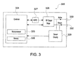
- FIG. 3 shows a block diagram of generator circuitry 305 of the generator 300 of FIG. 1 having a controller 324, a high voltage DC power supply 327 ("HVPS"), an RF output stage 328, and sensor circuitry 329.
- the HVPS 327 is connected to an AC source (e.g., electrical wall outlet) and provides high voltage DC power to an RF output stage 328, which then converts high voltage DC power into RF energy (e.g., an AC signal) and delivers the RF energy to the active terminal 330.
- the energy is returned thereto via the return terminal 332.
- the RF output stage 328 generates sinusoidal or rectangular waveforms of RF energy.
- the RF output stage 328 is configured to generate a plurality of waveforms having various duty cycles, peak voltages, waveform crest factors, and other suitable parameters. Certain types of waveforms are suitable for specific electrosurgical modes. For instance, the RF output stage 328 typically generates a 100% duty cycle sinusoidal waveform in cut mode, which is well-suited for ablating, fusing, and dissecting tissue, and a 1-25% duty cycle waveform in coagulation mode, which is suitable for cauterizing tissue to stop bleeding.
- the controller 324 includes a processor 325 operably connected to a memory 326, which may include volatile memory (e.g., RAM) and/or non-volatile memory (e.g., flash media, disk media, etc.).
- the processor 325 includes an output port that is operably connected to the HVPS 327 and/or RF output stage 328 allowing the processor 325 to control the output of the generator 300 according to either open and/or closed control loop schemes.
- a closed loop control scheme is a feedback control loop in which the sensor circuitry 329 provides feedback to controller 324 (i.e., information obtained from one or more sensors for sensing various tissue parameters such as tissue impedance, fluid presence, output current, and/or voltage, etc.), and providing feedback to the controller 324.
- the controller 324 then signals the HVPS 327 and/or RF output stage 328 to adjust the DC and/or RF power supply, respectively.
- the processor 325 may be substituted by using any logic processor (e.g., control circuit) adapted to perform the calculations and/or set of instructions described herein including, but not limited to, a field programmable gate array, a digital signal processor, or combinations of these logic processors.
- the processor 325 is coupled to the user interface 341 and is configured to modify modes, energy settings, and other parameters of the generator 300 in response to user input.
- the generator 300 is configured to operate in a variety of modes. In one embodiment, the generator 300 may generate an output according to the following modes: cut, blend, coagulate, division with hemostasis, fulgurate, spray, combinations of these modes, and the like. Each mode operates based on a pre-programmed power curve that controls the amount of power that is output by the generator 300 at varying impedances of the load (e.g., the target tissue). Each power curve includes power, voltage, and current control ranges that are defined by the user-selected power setting and the measured impedance of the load.
- the controller 324 of the generator 300 performs an optimized cutting algorithm for controlling the delivery of electrosurgical energy during a cutting procedure.
- the optimized cutting algorithm is configured to generate electrosurgical energy to target tissue in four phases, namely, impedance sense (IS), S1, S2 and S3, to effectively separate or divide the target tissue.
- the generator settings for each phase will now be described in further detail.
- the generator 300 will be set to an "off" or low power state to allow the target tissue to re-hydrate to lower the impedance of the target tissue after the application of electrosurgical energy.
- the output of the electrosurgical generator 300 is set to a power level P0 having a value from about 0 W to about 5 W and is typically set as close to 0W as possible.
- P0 is set slightly above 0W to provide a trickle of electrosurgical energy and provide enhanced system stability for a generator supplying electrosurgical energy at 0W.
- the electrosurgical generator After the IS phase 402 starts in step 501, the electrosurgical generator generates electrosurgical energy, which is output to the electrosurgical instrument and delivered to the target tissue by the electrosurgical instrument, at a constant power level P1 (step 504) for a set duration ISTsense (step 502) to allow the controller 324 of the generator circuitry 305 of FIG. 3 to determine initial parameters of the target tissue, for example, an initial tissue impedance Zlow. As shown in FIG. 5 , if it is determined in step 502 that the duration is greater than the set duration ISTsense, then Zlow is set equal to the sensed impedance at that time in step 506.
- Power level P1 is typically set to a power level from about 0 W to about 5 W and, in some embodiments, is set to 5 W.
- the duration ISTsense is typically set from about 10 ms to about 500 ms and, in some embodiments, is set to 100 ms to provide sufficient time for the sensor readings to stabilize. No appreciable changing of the tissue occurs during the application of electrosurgical energy to the target tissue during the IS phase.
- the generator 300 can determine whether the electrosurgical instrument is in an "open" state based on a comparison of the sensed initial tissue impedance Zlow to an upper threshold value Zsensehigh.
- an upper threshold value Zsensehigh of about 500 ⁇ to about 2000 ⁇ or more could be set for indicating that the instrument is in the "open” state, such as when there is no tissue disposed between the jaws of the instrument.
- the upper threshold value Zsensehigh may be set to 1500 ⁇ .
- the type of tissue may optionally be determined during the IS phase by comparing the initial tissue impedance Zlow to a threshold tissue impedance value TissueType, which is used to classify the target tissue as a low impedance tissue or a high impedance tissue.
- TissueType a threshold tissue impedance value
- the target tissue is set as a low impedance tissue in step 510.
- the low impedance tissue may require only one or two high-voltage pulses to divide tissue.
- the target tissue is set as a high impedance tissue in step 512.
- the high impedance tissue may require two or more high-voltage pulses for dividing the tissue.
- the electrosurgical generator 300 generates electrosurgical energy at a constant power level P3 in step 602 until it is determined in step 604 that the tissue impedance increases from the sensed initial impedance Zlow by a threshold impedance rise amount Zrise, i.e., until it is determined that the tissue impedance is greater than Zlow + Zrise, to prepare the tissue for cutting.
- Power level P3 is typically set to a power value from about 10 W to about 100 W and, in some embodiments, is set to 40 W.
- Zrise is typically set to an impedance value from about 5 ⁇ to about100 ⁇ and, in some embodiments, is set to 40 ⁇ .
- the electrosurgical energy is generated and applied to the target tissue at the power level P3 until the impedance of the target tissue has increased from the sensed initial impedance Zlow by Zrise to reach a threshold impedance value of Zlow + Zrise.
- step 604 the tissue has been pre-heated and the generator 300 is set to the "off" state to reduce or stop delivery of the electrosurgical energy to the target tissue by setting the power to power level P0 in step 610.
- the generator 300 is set to the "off" state for a duration TS1S2off before proceeding to the S2 phase 406 (steps 612 and 614). Setting the generator 300 to the "off" state before proceeding to the S2 phase 406 allows the target tissue to re-hydrate and reduces the impedance of the target tissue.
- TS1S2off is typically set to a duration from about 5ms to about 1000 ms and, in some embodiments, to 50 ms.
- S1ZriseLimit is typically set from about 0 ms to about 12000 ms and, in some embodiments, is set to 4000 ms.
- the electrosurgical generator 300 generates multiple pulses of electrosurgical energy at a constant power level P2 in step 706 to prepare the target tissue for cutting.
- Power level P2 is typically set to a power value from about 10 W to about 200 W and, in some embodiments, is set to 20 W.
- the output of the electrosurgical generator 300 is set to the "off" state having the power level P0 in step 712 for a fixed duration TS2off as determined in step 714 to allow the target tissue to at least partially re-hydrate.
- TS2off is typically set to a duration from about 5 ms to about 1000 ms and, in some embodiments, is set to 50ms.
- Each pulse has a variable duration based on a comparison in step 708 of a sensed impedance of the target tissue to a target impedance threshold, which is equal to a target impedance rise amount Ztarget above Zlow for the current pulse.
- the target impedance Ztarget for each successive pulse is adjusted by a multiplication factor Zmultiplier in step 710 such that each successive pulse drives the target tissue to a new target impedance.
- the target impedance Ztarget for each successive pulse at least one of increases, decreases, or remains the same.
- Ztarget is typically initialized to an impedance value from about 5 ⁇ to about 1000 ⁇ and, in some embodiments, Ztarget is initialized to 50 ⁇ .
- the multiplier Zmultiplier is typically set to a value of about 1.01 to about 10.0 and in some embodiments is set to 1.2.
- the multiplier Zmultiplier may be adjusted to increase or decrease the number of pulses in the S2 phase 406 and to increase or decrease the amount of time that the target tissue is cooked during each pulse. In some embodiments, the multiplier Zmultiplier may alternatively be set to a value that is less than or equal to 1.00 to either maintain or decrease the target impedance Ztarget for each pulse.
- the electrosurgical generator 300 continues to generate pulses in the S2 phase 406 until the sensed tissue impedance reaches a threshold value ZS2high above the initial tissue impedance Zlow.
- ZS2high is typically set from about 50 ⁇ to about 1000 ⁇ and, in some embodiments, is set to 100 ⁇ .
- the S2 phase 406 prepares the tissue for the final cutting by sequentially increasing the impedance of the target tissue in the cut zone to ensure a narrow band of desiccation for the final S3 phase 802.
- the generator Near the end of the S2 phase 406, the generator is set to the power "off" state and the power level is set to power level P0 in step 704 for a duration TS2S3off determined in step 716 to allow the target tissue to re-hydrate and reduce impedance before proceeding to the S3 phase 802 in step 718.
- TS2S3off is typically set to a duration from about 5ms to about 500 ms and, in some embodiments, is set to 100 ms.
- the electrosurgical generator 300 generates a high-voltage pulse of electrosurgical energy at a voltage level V1 and at a power level P4 in step 922 for a set duration S3Pulsetime determined in step 926 to divide the target tissue.
- Voltage level V1 for the high-voltage pulse of electrosurgical energy is typically set to a voltage from about 50 V to about 500 V.
- Power level P4 for the high-voltage pulse of electrosurgical energy is typically set to a power level from about 50 W to about 500 W and, in some embodiments, is set to 300 W.
- the duration S3Pulsetime of the high voltage pulse is typically set to a value from about 5 ms to about 500 ms and, in some embodiments, is set to 10 ms. In some embodiments, the duration S3Pulsetime of the high voltage pulse is determined in step 926 after it is determined that the sensed impedance of the target tissue reaches a threshold minimum tissue impedance value S3Zrise in step 924.
- the threshold minimum tissue impedance value S3Zrise is typically set from about 500 ⁇ to about 3000 ⁇ and, in some embodiments, is set to 1500 ⁇ .
- the high-voltage pulse at power level P4 during the S3 phase 802 is limited in duration to a maximum timeout value S3Pulsetime. If the sensed tissue impedance during the S3 high-voltage pulse does not reach the S3Zrise within a pre-determined time period S3PulseTime as determined in steps 924 and 926, the generator 300 shuts off the generation of electrosurgical energy.
- two or more high-voltage pulses may be needed to divide the target tissue.
- the maximum number of high-voltage pulses S3MaxPulses to be delivered to the target tissue may be based on a predefined setting in the generator or based on an operator setting set by the clinician performing the procedure. For example, lower impedance tissues, such as isolated veins, porcine uterine mesometrium, etc., typically need only one high-voltage pulse to divide the target tissue, while higher impedance tissues, such as thin tissue, fatty mesentery, etc., may require two or more high-voltage pulses to completely divide the target tissue.
- the type of tissue may be determined during the IS phase 402 by comparing the initial tissue impedance Zlow to a threshold tissue impedance value TissueType, which is used to classify the target tissue as a low impedance tissue or a high impedance tissue.
- TissueType a threshold tissue impedance value
- the target tissue is set as a low impedance tissue requiring only one or two high-voltage pulses for dividing the tissue.
- the initial tissue impedance Zlow is greater than or equal to the threshold tissue impedance value TissueType, the target tissue is set as a high impedance tissue requiring two or more high-voltage pulses for dividing the tissue.
- S3MaxPulses is set to three pulses.
- the threshold tissue impedance value TissueType can be set to an impedance value from about 25 ⁇ to about 500 ⁇ and, in some embodiments, is set to 100 ⁇ .
- the voltage level V1 for the high-voltage pulse may be adjusted based on the determined tissue type. For example, when the target tissue is determined to be a low impedance tissue, voltage level V1 may be set to 300 V and when the target tissue is determined to be a high impedance tissue, voltage level V1 may be set to 400 V.
- the generator is set to power level P0 after each high-voltage pulse for a duration S3offDuration to allow the target tissue to re-hydrate and reduce the tissue impedance for successive high voltage pulses.
- the duration S3offDuration can be set to a duration from about 10 ms to about 2000 ms and, in some embodiments, is set to 1000 ms.
- the number of high-voltage pulses of electrosurgical energy delivered to the target tissue may be controlled by the generator based on sensed tissue and/or instrument properties. For example, during the S3 phase 802, the electrosurgical generator 300 may continue to generate high-voltage pulses to the target tissue at the power level P4 until either a predetermined number of high-voltage pulses are generated as determined in step 910, the target tissue reaches a predefined impedance threshold S3ExitImpedance as determined in step 906, or the phase difference between the voltage and the current of the electrosurgical energy generated by the electrosurgical generator 300 exceeds a threshold phase difference S3ExitPhase as determined in step 908.
- the predefined impedance threshold S3ExitImpedance is typically set to an impedance value from about 500 ⁇ to about 5000 ⁇ and, in some embodiments, is set to 2600 ⁇ .
- the threshold phase difference S3ExitPhase is typically set to a phase shift from about 0.78 radians to about 1.56 radians and, in some embodiments, is set to 1.56 radians.
- the S3 phase 802 may include a pre-S3 impedance sense (IS) phase prior to each high-voltage pulse that is similar to the IS phase 402. If it is determined that the S3 phase 802 includes the pre-S3 IS phase 402 in step 920, the electrosurgical generator 300 initially generates electrosurgical energy before each high-voltage pulse at power level P1 in step 902 for the duration S3Tsense as determined in step 904 to help stabilize the sensor readings from sensor circuitry 329 before ramping up to the high voltage pulse at the power level P4 in step 922.
- the duration S3Tsense is typically set from about 10 ms to about 500 ms and, in some embodiments, is set to 100 ms to provide sufficient time for the sensor readings to stabilize. Applying electrosurgical energy at the power level P1 instead of the power level P0 before each high-voltage pulse was also found to be more favorable during testing for allowing the generator to achieve a rapid rise in power during the high-voltage pulse.
- the tissue and/or instrument properties are sensed to determine if any threshold exit conditions, such as the S3ExitImpedance, S3ExitPhase, or the pre-determined number of pulses have been met in steps 906, 908, and 910, respectively.
- the pre-S3 IS phase 402 before the first S3 pulse does not check for exit conditions such that at least one high-voltage pulse is always delivered to the target tissue to divide the target tissue.
- the S3 phase 802 may also or alternatively include a post-S3 impedance sense (IS) phase after each high-voltage pulse.
- the electrosurgical generator 300 ramps down from the high-voltage pulse at the power level P4 to deliver electrosurgical energy at the power level P1 for a duration S3Tsense to allow the sensor circuitry 329 to stabilize.
- the post-S3 IS phase 402 allows the sensor circuitry 329 to monitor the delayed impedance effect after the high-voltage pulse has completed. This allows sufficient time for the impedance to rise after the high-voltage pulse before checking for the threshold exit conditions, such as the S3ExitImpedance, the S3ExitPhase, or the number of pulses, in steps 906, 908, and 910, respectively.
- the tissue is determined to have been divided and the method ends in step 912.
- the generator 300 may also be deactivated or set to the power level P0. If none of the exit conditions have been met, it is determined whether the process has entered the post-S3 IS phase 402 in step 914. If it is determined that the process has entered the post-S3 IS phase 402, the generator 300 is powered “off” and set to the power level P0 in step 916. Then, it is determined in step 918 whether the power "off" duration is greater than a predetermined value, i.e., S3offDuration.
- the power "off” duration may start either immediately after the S3 high voltage pulse or instead may start after the post-S3 IS phase 402 has completed. After the power "off" duration reaches the S3offDuration, the process returns to step 902 in which the generator 300 is controlled to generate electrosurgical energy at the constant power level P1.
Landscapes
- Health & Medical Sciences (AREA)
- Life Sciences & Earth Sciences (AREA)
- Surgery (AREA)
- Engineering & Computer Science (AREA)
- Public Health (AREA)
- Molecular Biology (AREA)
- Veterinary Medicine (AREA)
- Physics & Mathematics (AREA)
- Biomedical Technology (AREA)
- Heart & Thoracic Surgery (AREA)
- Medical Informatics (AREA)
- Nuclear Medicine, Radiotherapy & Molecular Imaging (AREA)
- General Health & Medical Sciences (AREA)
- Animal Behavior & Ethology (AREA)
- Plasma & Fusion (AREA)
- Otolaryngology (AREA)
- Radiology & Medical Imaging (AREA)
- Biophysics (AREA)
- Pathology (AREA)
- Surgical Instruments (AREA)
Abstract
Description
- The present disclosure relates to systems and methods for operating an electrosurgical generator. More particularly, the present disclosure relates to a systems and methods for controlling the output of the electrosurgical generator for optimized cutting of tissue.
- Electrosurgery involves application of high radio frequency electrical current to a surgical site to cut, ablate, or coagulate tissue. In monopolar electrosurgery, a source or active electrode delivers alternating current from the electrosurgical generator to the targeted tissue and a return electrode conducts the alternating current back to the generator. A patient return electrode is placed remotely from the active electrode to conduct the current back to the generator.
- In bipolar electrosurgery return and active electrodes are placed in close proximity to each other such that an electrical circuit is formed between the two electrodes (e.g., in the case of an electrosurgical forceps). In this manner, the applied alternating current is limited to the body tissue positioned between the electrodes. Accordingly, bipolar electrosurgery generally involves the use of instruments where it is desired to achieve a focused delivery of electrosurgical energy between two electrodes positioned on the instrument, e.g., forceps or the like. A forceps is a pliers-like instrument which relies on mechanical action between its jaws to grasp, clamp, and constrict vessels or tissue. Electrosurgical forceps (open or endoscopic) utilize mechanical clamping action and electrical energy to effect hemostasis on the clamped tissue. The forceps include electrosurgical conductive surfaces which apply the electrosurgical energy to the clamped tissue. By controlling the intensity, frequency, and duration of the electrosurgical energy applied through the conductive plates to the tissue, the surgeon can coagulate, seal, and/or cut tissue. However, the above example is for illustrative purposes only and there are many other known bipolar electrosurgical instruments which are within the scope of the present disclosure.
- The systems and methods according to embodiments of the present disclosure provide optimal tissue effect during an electrosurgical procedure. According to one embodiment, the present disclosure provides for a method for controlling an electrosurgical generator.
- In accordance with aspects of the present disclosure, a method for controlling an electrosurgical generator is provided including sensing an impedance of target tissue; generating electrosurgical energy in a first phase at a first power level until the sensed impedance of the target tissue is greater than a first threshold impedance; generating a plurality of pulses of electrosurgical energy in a second phase at a second power level, each pulse being generated until the sensed impedance of the target tissue is greater than a second threshold impedance set for that pulse; and generating at least one high-voltage pulse in a third phase at a third power level for a predetermined duration to divide the target tissue. The high voltage pulse has a higher voltage than that of the pulses in the second phase and that of the electrosurgical energy in the first phase.
- In an aspect, the first phase is adapted to pre-cook the target tissue.
- In an aspect, each pulse of the second phase is adapted to cook the tissue and the second phase is adapted to precondition the target tissue for division during the third phase.
- In an aspect, the first power level is higher than the second power level.
- In an aspect, the second threshold impedance for each pulse in the second phase is greater than the first threshold impedance.
- In an aspect, the third power level is higher than the first and second power levels.
- In some aspects of the present disclosure, the method further includes generating electrosurgical energy in an impedance sense phase at a fourth power level to sense an initial tissue impedance of the target tissue. The impedance sense phase may be configured so that no applicable change in the target tissue occurs.
- In some aspects of the present disclosure, the first threshold impedance is equal to a predetermined impedance rise amount above the initial tissue impedance.
- In some aspects of the present disclosure, the second threshold impedance is equal to an adjustable impedance rise amount above the initial tissue impedance.
- In some aspects of the present disclosure, the adjustable impedance rise amount at least one of increases, decreases, and remains the same for each successive pulse based on an adjustment factor.
- In some aspects of the present disclosure, the adjustable impedance rise amount is multiplied by the adjustment factor for each successive pulse.
- In some aspects, the second threshold impedance is set to increase or decrease, preferably increase, for each successive pulse in the second phase.
- In some aspects of the present disclosure, the pulses in the second phase are applied until the sensed tissue impedance is greater than a maximum threshold impedance value.
- In some aspects of the present disclosure, the method further includes determining a tissue type of the target tissue based on the sensed initial impedance of the target tissue; and generating a number of high-voltage pulses during the third phase based on the determined tissue type or setting a voltage level of the at least one high voltage pulse based on the determined tissue type.
- In some aspects of the present disclosure, if the sensed initial impedance of the target tissue is less than a tissue type threshold impedance value, the tissue type is determined to be a low impedance tissue type and the number of high-voltage pulses delivered during the third phase is set to a first value, and if the sensed initial impedance of the target tissue is greater than or equal to the tissue type threshold impedance value, the tissue type is determined to be a high impedance tissue type and the number of high-voltage pulses generated during the third phase is set to a second value, the second value being greater than the first value.
- In some aspects of the present disclosure, the method further includes stopping the generation of at least one high-voltage pulse during the third phase if the sensed impedance of the target tissue exceeds a maximum threshold impedance value.
- In some aspects of the present disclosure, the method further includes stopping the generation of at least one high-voltage pulse during the third phase if a phase difference between the voltage and current of the at least one high-voltage pulse is greater than a predetermined phase difference value.
- In some aspects of the present disclosure, the generator is set to an off state having a fifth power level after each pulse of the plurality of pulses in the second phase for a predetermined duration, the predetermined duration being set such that the target tissue at least partially re-hydrates after each pulse of the plurality of pulses. The fifth power level may be zero Watts or substantially zero Watts.
- In some aspects of the present disclosure, the generator is set to an off state having a fifth power level after each pulse of the at least one high-voltage pulse in the third phase for a pre-determined duration, the pre-determined duration being set such that the target tissue at least partially re-hydrates after each pulse. The pre-determined duration in the third phase may be greater than the pre-determined duration in the second phase.
- In some aspects of the present disclosure, the generator is set to an off state having a fifth power level after each pulse generated in the first, second, and third phases, each off state having a pre-determined duration. The pre-determined duration after the pulses in the third phase may be greater than the pre-determined duration after the electrosurgical energy in the first phase and/or the pre-determined duration after the pulses in the second phase.
- In some aspects of the present disclosure, the generator is set to an off state having a fifth power level between the first phase and the second phase and/or between the second phase and the third phase to allow the target tissue to at least partially re-hydrate.
- In some aspects of the present disclosure, the method further includes generating, in the third phase, electrosurgical energy at a/the fourth power level before the at least one high-voltage pulse to sense the impedance of the target tissue and prepare the generator for a rapid rise in power to the third power level. The electrosurgical energy applied at the fourth power level before the at least one high-voltage pulse is such that no appreciable change in target tissue occurs.
- In some aspects of the present disclosure, the method further includes generating, in the third phase, electrosurgical energy at the fourth power level after that at least one high-voltage pulse to sense the impedance of the target tissue.
- In accordance with aspects of the present disclosure, an electrosurgical generator is provided including an RF output stage coupled to a power source, a sensor configured to measure an impedance of the target tissue; and a controller configured to control the RF output. The RF output stage is configured to generate electrosurgical energy from power provided by the power source for delivery to target tissue. The controller is configured to control the RF output stage to: generate electrosurgical energy in a first phase at a first power level until the sensed impedance of the target tissue is greater than a first threshold impedance; generate a plurality of pulses of electrosurgical energy in a second phase at a second power level, each pulse of the plurality of pulses being generated until the sensed impedance of the target tissue is greater than a second threshold impedance set for that pulse; and generate at least one high-voltage pulse in a third phase at a third power level for a predetermined duration to divide the target tissue.
- In some aspects of the present disclosure, the first threshold impedance is equal to a predetermined impedance rise amount above an initial tissue impedance measured by the sensor.
- In some aspects of the present disclosure, the second threshold impedance is equal to an adjustable impedance rise amount above an initial tissue impedance measured by the sensor.
- In some aspects of the present disclosure, the adjustable impedance rise amount at least one of increases, decreases, and remains the same for each successive pulse based on an adjustment factor, the adjustable impedance rise amount being multiplied by the adjustment factor for each successive pulse. The features described above with respect to the method aspects are applicable to the generator aspects in that the controller is configured to perform the method aspects.
- In accordance with aspects of the present disclosure, a method for treating target tissue is provided including delivering electrosurgical energy to the target tissue in a first phase at a first power level until a sensed tissue impedance of the target tissue is greater than a threshold target impedance; delivering a plurality of pulses of electrosurgical energy to the target tissue in a second phase at a second power level, each pulse being delivered until the sensed tissue impedance of the target tissue is greater than a threshold target impedance set for that pulse; and delivering at least one high voltage pulse to the target tissue in a third phase at a third power level for a pre-determined duration to divide the target tissue.
- In accordance with aspects of the present disclosure, a method for controlling an electrosurgical generator is provided including sensing an impedance of target tissue; generating electrosurgical energy in an impedance sense phase at an initial power level for a first duration to sense an initial tissue impedance of the target tissue; generating electrosurgical energy in a first phase at a first power level until the sensed impedance of the target tissue is greater than a first threshold impedance; and generating a plurality of pulses of electrosurgical energy in a second phase at a second power level, each pulse being generated until the sensed impedance of the target tissue is greater than a second threshold impedance set for that pulse.
- In some aspects of the present disclosure, the initial power level and the first duration are set so that the generated electrosurgical energy has little effect on the target tissue.
- The method aspects described above relating to the first and second phases and the impedance sense phase are applicable to this method aspect.
- In further aspects, the method aspects may be formulated as computer readable instructions for controlling an electrosurgical generator, which, when executed by a controller of the electrosurgical generator, carry out the stated method.
- Any of the above aspects and embodiments of the present disclosure may be combined without departing from the scope of the present disclosure.
- Various embodiments of the present disclosure are described herein with reference to the drawings wherein:
-
FIG. 1 is a perspective view of an electrosurgical generator and other components of an electrosurgical system according to embodiments of the present disclosure; -
FIG. 2 is a front view of the electrosurgical generator ofFIG. 1 ; -
FIG. 3 is a block diagram of the generator circuitry of the electrosurgical generator ofFIG. 2 ; -
FIG. 4 is a graphical diagram illustrating the output power profile of the electrosurgical energy generated by the generator circuitry ofFIG. 3 as a function of time for three phases according to an embodiment of the present disclosure; -
Figs. 5-7 are flowcharts illustrating a method of controlling the power output from the generator circuitry during different operational phases according to embodiments of the present disclosure; -
FIG. 8 is a graphical diagram illustrating the output power profile of the electrosurgical energy generated by the generator circuitry ofFIG. 3 as a function of time for another phase according to an embodiment of the present disclosure; and -
FIG. 9 is a flowchart illustrating a method of controlling the power output from the generator circuitry during another phase according to embodiments of the present disclosure. - Particular embodiments of the present disclosure are described below with reference to the accompanying drawings. In the following description, well-known functions or constructions are not described in detail to avoid obscuring the present disclosure in unnecessary detail.
- The present disclosure provides for a system and method for cutting tissue. The method may be implemented as computer-readable instructions executed by a controller, e.g., a microcontroller, of the electrosurgical generator. The generator includes an RF output stage configured to supply electrosurgical energy to tissue via at least one active electrode configured to apply electrosurgical energy to tissue, sensing circuitry configured to measure impedance of tissue, and the controller. The generator according to the present disclosure can perform monopolar and/or bipolar electrosurgical procedures, including, for example, cutting, coagulation, ablation, and vessel sealing procedures.
- The generator may include a plurality of outputs for interfacing with various electrosurgical instruments (e.g., a monopolar instrument, return electrode, bipolar electrosurgical forceps, footswitch, etc.). Further, the generator includes electronic circuitry configured to generate radio frequency energy specifically suited for various electrosurgical modes (e.g., cut, blend, coagulate, division with hemostasis, fulgurate, spray, etc.) and procedures (e.g., monopolar, bipolar, vessel sealing, etc.). In embodiments, the generator may be embedded, integrated, or otherwise coupled to the electrosurgical instruments providing for an all-in-one electrosurgical apparatus.
- The systems and methods of the present disclosure provide for optimal tissue effect in an electrosurgical cutting procedure. The method is performed over the following operational phases: (1) initialize the tissue effect, (2) localize heat in the target tissue through impedance-based pulsing, and (3) separate tissue with focused energy density. In the first phase, power is delivered to the target tissue until the tissue impedance rises above a threshold. Then energy delivery is paused for an intermediate off state to allow for tissue rehydration. The purpose of the first phase is to get the target tissue cooking, but not to over-desiccate the target tissue before any significant energy delivery.
- Prior to the first phase, the method may also include a fourth phase in which a small amount of power is delivered to the target tissue to sense the initial impedance of the target tissue. The sensed initial impedance of the target tissue is used to determine the current state of the instrument (e.g., to confirm that the instrument is not in an open circuit state) and to stabilize the sensor readings.
- In the second phase, the power output from the generator is pulsed at a constant rate to steadily raise the tissue impedance. This pulsing preconditions the tissue in the cut zone of the target tissue to ensure a narrow band of desiccation for the third phase. In embodiments, the second phase does not over-desiccate the tissue prior to the third phase.
- In the third phase, one or more high-voltage pulses are delivered for a prescribed amount or time. These pulses deliver the final burst of energy needed to divide the tissue in the cut zone of the target tissue. The third phase incorporates intelligent impedance-based pulsing to ensure tissue separation. It has been found that lower impedance tissues (e.g., isolated veins, porcine uterine mesometrium, etc.) typically only need one high-voltage pulse to divide the target tissue, while higher-impedance tissues (e.g., thin tissue, fatty mesentery, etc.) need two or more pulses to completely divide the target tissue. Thus, in the third phase, pulses are continually generated and delivered to the target tissue until a predetermined number of pulses have been generated or the tissue reaches a threshold impedance indicating that the tissue has already been divided. This enables a more intelligent shut-off of the cutting algorithm and ensures a complete cut.
-
FIG. 1 is an illustration of a monopolar andbipolar electrosurgical system 10 according to the present disclosure. Thesystem 10 may include one or more monopolarelectrosurgical instruments 12 having one or more active electrodes 13 (e.g., electrosurgical cutting probe, ablation electrodes, etc.) for treating tissue of a patient. Electrosurgical alternating current is supplied to theinstrument 12 by agenerator 300 via asupply line 14 that is connected to an active terminal 230 (FIG. 3 ) of thegenerator 300, allowing theinstrument 12 to cut, coagulate, ablate, and/or otherwise treat tissue. The alternating current is returned to thegenerator 300 through areturn electrode pad 16 via areturn line 18 at a return terminal 332 (FIG. 3 ) of thegenerator 300. For monopolar operation, thesystem 10 may include a plurality ofreturn electrode pads 16 that, in use, are disposed on a patient to minimize the chances of tissue damage by maximizing the overall contact area with the patient. In addition, thegenerator 300 and thereturn electrode pads 16 may be configured for monitoring so-called "tissue-to-patient" contact to insure that sufficient contact exists therebetween to further minimize chances of tissue damage. - The
system 10 may also include one or more bipolar electrosurgical instruments, for example, a bipolarelectrosurgical forceps 110 or a bipolar electrosurgical forceps 310 having one or more electrodes for treating tissue of a patient. The bipolar electrosurgical instruments may be used with open and/or laparoscopic surgical procedures. - The bipolar
electrosurgical forceps 110 includes ahousing 111 and opposingjaw members shaft 112. Thejaw members active electrodes 114 and areturn electrode 116 disposed therein, respectively. Theactive electrode 114 and thereturn electrode 116 are connected to thegenerator 300 throughcable 118 that includes the supply and returnlines terminals FIG. 3 ). Theelectrosurgical forceps 110 is coupled to thegenerator 300 at a connector having connections to the active and returnterminals 330 and 332 (e.g., pins) via a plug disposed at the end of thecable 118, wherein the plug includes contacts from the supply and returnlines - The bipolar
electrosurgical forceps 210 includes amechanical forceps 220 having anend effector 224 and adisposable electrode assembly 221.Mechanical forceps 220 includes first and secondelongated shaft members shaft members handle members shaft members end effector 224 includes opposingjaw members shaft members jaw members shaft members housing 270 having a pair ofhousing halves shaft member 214.Forceps 210 includes anelectrical cable 228 extending fromhousing 270 configured to electrically connectforceps 210 to a source of electrosurgical energy, such aselectrosurgical generator 300, as shown inFIG. 1 . - With reference to
FIG. 2 , afront face 340 of thegenerator 300 is shown. Thegenerator 300 may be any suitable type (e.g., electrosurgical, microwave, etc.) and may include a plurality of connectors 350-362 to accommodate various types of electrosurgical instruments (e.g.,electrosurgical instrument 12,electrosurgical forceps 110,electrosurgical forceps 210, etc.). - The
generator 300 includes auser interface 341 having one or more display screens orinformation panels generator 300 includes suitable input controls (e.g., buttons, activators, switches, touch screen, etc.) for controlling thegenerator 300. The display screens 342, 344, 346 are also configured as touch screens that display a corresponding menu for the electrosurgical instruments (e.g.,electrosurgical instrument 12,electrosurgical forceps 110,electrosurgical forceps 210, etc.). The user then adjusts inputs by simply touching corresponding menu options. -
Display screen 342 controls monopolar output and the devices connected to theconnectors Connector 350 is configured to couple to a monopolar electrosurgical instrument (e.g., electrosurgical instrument 12) andconnector 352 is configured to couple to a foot switch (not shown). The foot switch provides for additional inputs (e.g., replicating inputs of the generator 300).Display screen 344 controls monopolar and bipolar output and the devices connected to theconnectors Connector 356 is configured to couple to other monopolar instruments.Connector 358 is configured to couple to a bipolar instrument. -
Display screen 346 controls bipolar sealing procedures performed by theforceps 110 orforceps 210 that may be plugged into theconnectors generator 300 outputs energy through theconnectors forceps display screen 346 outputs a user interface that allows the user to input a user-defined intensity setting. The user-defined intensity setting may be any setting that allows the user to adjust one or more energy delivery parameters, such as power, current, voltage, energy, etc. or sealing parameters, such as energy rate limiters, sealing duration, etc. The user-defined setting is transmitted to thecontroller 324 where the setting may be saved inmemory 326. In embodiments, the intensity setting may be a number scale, such as for example, from one to ten or one to five. In embodiments, the intensity setting may be associated with an output curve of thegenerator 300. The intensity settings may be specific for eachforceps forceps -
FIG. 3 shows a block diagram ofgenerator circuitry 305 of thegenerator 300 ofFIG. 1 having acontroller 324, a high voltage DC power supply 327 ("HVPS"), anRF output stage 328, andsensor circuitry 329. TheHVPS 327 is connected to an AC source (e.g., electrical wall outlet) and provides high voltage DC power to anRF output stage 328, which then converts high voltage DC power into RF energy (e.g., an AC signal) and delivers the RF energy to theactive terminal 330. The energy is returned thereto via thereturn terminal 332. In particular, theRF output stage 328 generates sinusoidal or rectangular waveforms of RF energy. TheRF output stage 328 is configured to generate a plurality of waveforms having various duty cycles, peak voltages, waveform crest factors, and other suitable parameters. Certain types of waveforms are suitable for specific electrosurgical modes. For instance, theRF output stage 328 typically generates a 100% duty cycle sinusoidal waveform in cut mode, which is well-suited for ablating, fusing, and dissecting tissue, and a 1-25% duty cycle waveform in coagulation mode, which is suitable for cauterizing tissue to stop bleeding. - The
controller 324 includes aprocessor 325 operably connected to amemory 326, which may include volatile memory (e.g., RAM) and/or non-volatile memory (e.g., flash media, disk media, etc.). Theprocessor 325 includes an output port that is operably connected to theHVPS 327 and/orRF output stage 328 allowing theprocessor 325 to control the output of thegenerator 300 according to either open and/or closed control loop schemes. A closed loop control scheme is a feedback control loop in which thesensor circuitry 329 provides feedback to controller 324 (i.e., information obtained from one or more sensors for sensing various tissue parameters such as tissue impedance, fluid presence, output current, and/or voltage, etc.), and providing feedback to thecontroller 324. Thecontroller 324 then signals theHVPS 327 and/orRF output stage 328 to adjust the DC and/or RF power supply, respectively. Those skilled in the art will appreciate that theprocessor 325 may be substituted by using any logic processor (e.g., control circuit) adapted to perform the calculations and/or set of instructions described herein including, but not limited to, a field programmable gate array, a digital signal processor, or combinations of these logic processors. - The
processor 325 is coupled to theuser interface 341 and is configured to modify modes, energy settings, and other parameters of thegenerator 300 in response to user input. Thegenerator 300 is configured to operate in a variety of modes. In one embodiment, thegenerator 300 may generate an output according to the following modes: cut, blend, coagulate, division with hemostasis, fulgurate, spray, combinations of these modes, and the like. Each mode operates based on a pre-programmed power curve that controls the amount of power that is output by thegenerator 300 at varying impedances of the load (e.g., the target tissue). Each power curve includes power, voltage, and current control ranges that are defined by the user-selected power setting and the measured impedance of the load. - Referring now to
FIGS. 4-9 , thecontroller 324 of thegenerator 300 performs an optimized cutting algorithm for controlling the delivery of electrosurgical energy during a cutting procedure. The optimized cutting algorithm is configured to generate electrosurgical energy to target tissue in four phases, namely, impedance sense (IS), S1, S2 and S3, to effectively separate or divide the target tissue. The generator settings for each phase will now be described in further detail. In some instances, thegenerator 300 will be set to an "off" or low power state to allow the target tissue to re-hydrate to lower the impedance of the target tissue after the application of electrosurgical energy. In the "off" state, the output of theelectrosurgical generator 300 is set to a power level P0 having a value from about 0 W to about 5 W and is typically set as close to 0W as possible. In some embodiments, P0 is set slightly above 0W to provide a trickle of electrosurgical energy and provide enhanced system stability for a generator supplying electrosurgical energy at 0W. - Referring now to
FIGS. 4 and5 , after theIS phase 402 starts instep 501, the electrosurgical generator generates electrosurgical energy, which is output to the electrosurgical instrument and delivered to the target tissue by the electrosurgical instrument, at a constant power level P1 (step 504) for a set duration ISTsense (step 502) to allow thecontroller 324 of thegenerator circuitry 305 ofFIG. 3 to determine initial parameters of the target tissue, for example, an initial tissue impedance Zlow. As shown inFIG. 5 , if it is determined instep 502 that the duration is greater than the set duration ISTsense, then Zlow is set equal to the sensed impedance at that time instep 506. Power level P1 is typically set to a power level from about 0 W to about 5 W and, in some embodiments, is set to 5 W. The duration ISTsense is typically set from about 10 ms to about 500 ms and, in some embodiments, is set to 100 ms to provide sufficient time for the sensor readings to stabilize. No appreciable changing of the tissue occurs during the application of electrosurgical energy to the target tissue during the IS phase. - By applying electrosurgical energy to tissue at power level P1 for a duration ISTsense, the
generator 300 can determine whether the electrosurgical instrument is in an "open" state based on a comparison of the sensed initial tissue impedance Zlow to an upper threshold value Zsensehigh. For example, an upper threshold value Zsensehigh of about 500 Ω to about 2000 Ω or more could be set for indicating that the instrument is in the "open" state, such as when there is no tissue disposed between the jaws of the instrument. In some embodiments, the upper threshold value Zsensehigh may be set to 1500 Ω. - In some embodiments, the type of tissue may optionally be determined during the IS phase by comparing the initial tissue impedance Zlow to a threshold tissue impedance value TissueType, which is used to classify the target tissue as a low impedance tissue or a high impedance tissue. For example, when the initial tissue impedance Zlow is determined to be smaller than the threshold tissue impedance value TissueType (i.e., the initial tissue impedance Zlow is determined not to be greater than or equal to the threshold tissue impedance value TissueType) in
step 508, the target tissue is set as a low impedance tissue instep 510. The low impedance tissue may require only one or two high-voltage pulses to divide tissue. On the other hand, when the initial tissue impedance Zlow is determined to be greater than or equal to the threshold tissue impedance value TissueType instep 508, the target tissue is set as a high impedance tissue instep 512. The high impedance tissue may require two or more high-voltage pulses for dividing the tissue. After the type of the tissue has been determined and set, the IS phase ends and the process exits the IS phase and proceeds to the first phase S1 instep 514. - Referring now to
FIGS. 4 and6 , during theS1 phase 404 or pre-cooking phase, which starts instep 601, theelectrosurgical generator 300 generates electrosurgical energy at a constant power level P3 instep 602 until it is determined instep 604 that the tissue impedance increases from the sensed initial impedance Zlow by a threshold impedance rise amount Zrise, i.e., until it is determined that the tissue impedance is greater than Zlow + Zrise, to prepare the tissue for cutting. Power level P3 is typically set to a power value from about 10 W to about 100 W and, in some embodiments, is set to 40 W. Zrise is typically set to an impedance value from about 5 Ω to about100 Ω and, in some embodiments, is set to 40 Ω. The electrosurgical energy is generated and applied to the target tissue at the power level P3 until the impedance of the target tissue has increased from the sensed initial impedance Zlow by Zrise to reach a threshold impedance value of Zlow + Zrise. - Once it is determined in
step 604 that the sensed impedance of the target tissue has reached Zlow + Zrise, the tissue has been pre-heated and thegenerator 300 is set to the "off" state to reduce or stop delivery of the electrosurgical energy to the target tissue by setting the power to power level P0 instep 610. Thegenerator 300 is set to the "off" state for a duration TS1S2off before proceeding to the S2 phase 406 (steps 612 and 614). Setting thegenerator 300 to the "off" state before proceeding to theS2 phase 406 allows the target tissue to re-hydrate and reduces the impedance of the target tissue. TS1S2off is typically set to a duration from about 5ms to about 1000 ms and, in some embodiments, to 50 ms. - If it is determined in
step 606 that the sensed impedance of the target tissue does not reach Zlow + Zrise within a time S1ZriseLimit, the output from theelectrosurgical generator 300 is shut off and the cutting algorithm is stopped instep 608 due to a lack of tissue response to the application of electrosurgical energy. S1ZriseLimit is typically set from about 0 ms to about 12000 ms and, in some embodiments, is set to 4000 ms. - Referring now to
FIGS. 4 and7 , during theS2 phase 406, which starts instep 701, theelectrosurgical generator 300 generates multiple pulses of electrosurgical energy at a constant power level P2 instep 706 to prepare the target tissue for cutting. Power level P2 is typically set to a power value from about 10 W to about 200 W and, in some embodiments, is set to 20 W. After each pulse, the output of theelectrosurgical generator 300 is set to the "off" state having the power level P0 instep 712 for a fixed duration TS2off as determined instep 714 to allow the target tissue to at least partially re-hydrate. TS2off is typically set to a duration from about 5 ms to about 1000 ms and, in some embodiments, is set to 50ms. - Each pulse has a variable duration based on a comparison in
step 708 of a sensed impedance of the target tissue to a target impedance threshold, which is equal to a target impedance rise amount Ztarget above Zlow for the current pulse. When it is determined instep 708 that the sensed impedance of the target tissue is greater than Ztarget + Zlow, the target impedance Ztarget for each successive pulse is adjusted by a multiplication factor Zmultiplier instep 710 such that each successive pulse drives the target tissue to a new target impedance. In some embodiments, the target impedance Ztarget for each successive pulse at least one of increases, decreases, or remains the same. - Ztarget is typically initialized to an impedance value from about 5 Ω to about 1000 Ω and, in some embodiments, Ztarget is initialized to 50 Ω. The multiplier Zmultiplier is typically set to a value of about 1.01 to about 10.0 and in some embodiments is set to 1.2. The multiplier Zmultiplier may be adjusted to increase or decrease the number of pulses in the
S2 phase 406 and to increase or decrease the amount of time that the target tissue is cooked during each pulse. In some embodiments, the multiplier Zmultiplier may alternatively be set to a value that is less than or equal to 1.00 to either maintain or decrease the target impedance Ztarget for each pulse. Theelectrosurgical generator 300 continues to generate pulses in theS2 phase 406 until the sensed tissue impedance reaches a threshold value ZS2high above the initial tissue impedance Zlow. ZS2high is typically set from about 50 Ω to about 1000 Ω and, in some embodiments, is set to 100 Ω. - The
S2 phase 406 prepares the tissue for the final cutting by sequentially increasing the impedance of the target tissue in the cut zone to ensure a narrow band of desiccation for thefinal S3 phase 802. Near the end of theS2 phase 406, the generator is set to the power "off" state and the power level is set to power level P0 instep 704 for a duration TS2S3off determined instep 716 to allow the target tissue to re-hydrate and reduce impedance before proceeding to theS3 phase 802 instep 718. TS2S3off is typically set to a duration from about 5ms to about 500 ms and, in some embodiments, is set to 100 ms. - Referring now to
FIGS. 8 and9 , during theS3 phase 802, which starts instep 901, theelectrosurgical generator 300 generates a high-voltage pulse of electrosurgical energy at a voltage level V1 and at a power level P4 instep 922 for a set duration S3Pulsetime determined instep 926 to divide the target tissue. Voltage level V1 for the high-voltage pulse of electrosurgical energy is typically set to a voltage from about 50 V to about 500 V. Power level P4 for the high-voltage pulse of electrosurgical energy is typically set to a power level from about 50 W to about 500 W and, in some embodiments, is set to 300 W. - The duration S3Pulsetime of the high voltage pulse is typically set to a value from about 5 ms to about 500 ms and, in some embodiments, is set to 10 ms. In some embodiments, the duration S3Pulsetime of the high voltage pulse is determined in
step 926 after it is determined that the sensed impedance of the target tissue reaches a threshold minimum tissue impedance value S3Zrise instep 924. The threshold minimum tissue impedance value S3Zrise is typically set from about 500 Ω to about 3000 Ω and, in some embodiments, is set to 1500 Ω. The high-voltage pulse at power level P4 during theS3 phase 802 is limited in duration to a maximum timeout value S3Pulsetime. If the sensed tissue impedance during the S3 high-voltage pulse does not reach the S3Zrise within a pre-determined time period S3PulseTime as determined insteps generator 300 shuts off the generation of electrosurgical energy. - In some procedures, two or more high-voltage pulses may be needed to divide the target tissue. The maximum number of high-voltage pulses S3MaxPulses to be delivered to the target tissue may be based on a predefined setting in the generator or based on an operator setting set by the clinician performing the procedure. For example, lower impedance tissues, such as isolated veins, porcine uterine mesometrium, etc., typically need only one high-voltage pulse to divide the target tissue, while higher impedance tissues, such as thin tissue, fatty mesentery, etc., may require two or more high-voltage pulses to completely divide the target tissue.
- As described above with respect to
FIG. 5 , the type of tissue may be determined during theIS phase 402 by comparing the initial tissue impedance Zlow to a threshold tissue impedance value TissueType, which is used to classify the target tissue as a low impedance tissue or a high impedance tissue. For example, when the initial tissue impedance Zlow is smaller than the threshold tissue impedance value TissueType, the target tissue is set as a low impedance tissue requiring only one or two high-voltage pulses for dividing the tissue. When the initial tissue impedance Zlow is greater than or equal to the threshold tissue impedance value TissueType, the target tissue is set as a high impedance tissue requiring two or more high-voltage pulses for dividing the tissue. In some embodiments, S3MaxPulses is set to three pulses. The threshold tissue impedance value TissueType can be set to an impedance value from about 25 Ω to about 500 Ω and, in some embodiments, is set to 100 Ω. The voltage level V1 for the high-voltage pulse may be adjusted based on the determined tissue type. For example, when the target tissue is determined to be a low impedance tissue, voltage level V1 may be set to 300 V and when the target tissue is determined to be a high impedance tissue, voltage level V1 may be set to 400 V. - When the
S3 phase 802 includes more than one high-voltage pulse, the generator is set to power level P0 after each high-voltage pulse for a duration S3offDuration to allow the target tissue to re-hydrate and reduce the tissue impedance for successive high voltage pulses. By halting the supply of high-voltage energy to the target tissue between high-voltage pulses, optimized cutting of the target tissue can be achieved while minimizing the impact on surrounding tissue. The duration S3offDuration can be set to a duration from about 10 ms to about 2000 ms and, in some embodiments, is set to 1000 ms. - In some embodiments, the number of high-voltage pulses of electrosurgical energy delivered to the target tissue may be controlled by the generator based on sensed tissue and/or instrument properties. For example, during the
S3 phase 802, theelectrosurgical generator 300 may continue to generate high-voltage pulses to the target tissue at the power level P4 until either a predetermined number of high-voltage pulses are generated as determined instep 910, the target tissue reaches a predefined impedance threshold S3ExitImpedance as determined instep 906, or the phase difference between the voltage and the current of the electrosurgical energy generated by theelectrosurgical generator 300 exceeds a threshold phase difference S3ExitPhase as determined instep 908. The predefined impedance threshold S3ExitImpedance is typically set to an impedance value from about 500 Ω to about 5000 Ω and, in some embodiments, is set to 2600 Ω. The threshold phase difference S3ExitPhase is typically set to a phase shift from about 0.78 radians to about 1.56 radians and, in some embodiments, is set to 1.56 radians. - In some embodiments, the
S3 phase 802 may include a pre-S3 impedance sense (IS) phase prior to each high-voltage pulse that is similar to theIS phase 402. If it is determined that theS3 phase 802 includes the pre-S3 ISphase 402 instep 920, theelectrosurgical generator 300 initially generates electrosurgical energy before each high-voltage pulse at power level P1 instep 902 for the duration S3Tsense as determined instep 904 to help stabilize the sensor readings fromsensor circuitry 329 before ramping up to the high voltage pulse at the power level P4 instep 922. The duration S3Tsense is typically set from about 10 ms to about 500 ms and, in some embodiments, is set to 100 ms to provide sufficient time for the sensor readings to stabilize. Applying electrosurgical energy at the power level P1 instead of the power level P0 before each high-voltage pulse was also found to be more favorable during testing for allowing the generator to achieve a rapid rise in power during the high-voltage pulse. - During the pre-S3 IS
phase 402, the tissue and/or instrument properties are sensed to determine if any threshold exit conditions, such as the S3ExitImpedance, S3ExitPhase, or the pre-determined number of pulses have been met insteps phase 402 before the first S3 pulse does not check for exit conditions such that at least one high-voltage pulse is always delivered to the target tissue to divide the target tissue. - In some embodiments, the
S3 phase 802 may also or alternatively include a post-S3 impedance sense (IS) phase after each high-voltage pulse. Theelectrosurgical generator 300 ramps down from the high-voltage pulse at the power level P4 to deliver electrosurgical energy at the power level P1 for a duration S3Tsense to allow thesensor circuitry 329 to stabilize. The post-S3 ISphase 402 allows thesensor circuitry 329 to monitor the delayed impedance effect after the high-voltage pulse has completed. This allows sufficient time for the impedance to rise after the high-voltage pulse before checking for the threshold exit conditions, such as the S3ExitImpedance, the S3ExitPhase, or the number of pulses, insteps - Once one of the exit conditions in
steps step 912. Instep 912, thegenerator 300 may also be deactivated or set to the power level P0. If none of the exit conditions have been met, it is determined whether the process has entered the post-S3 ISphase 402 instep 914. If it is determined that the process has entered the post-S3 ISphase 402, thegenerator 300 is powered "off" and set to the power level P0 instep 916. Then, it is determined instep 918 whether the power "off" duration is greater than a predetermined value, i.e., S3offDuration. The power "off" duration may start either immediately after the S3 high voltage pulse or instead may start after the post-S3 ISphase 402 has completed. After the power "off" duration reaches the S3offDuration, the process returns to step 902 in which thegenerator 300 is controlled to generate electrosurgical energy at the constant power level P1. - While several embodiments of the disclosure have been shown in the drawings and/or described herein, it is not intended that the disclosure be limited thereto, as it is intended that the disclosure be as broad in scope as the art will allow and that the specification be read likewise. Therefore, the above description should not be construed as limiting, but merely as exemplifications of particular embodiments. Those skilled in the art will envision other modifications within the scope and spirit of the claims appended hereto.
- The following numbered items form part of the present disclosure:
- 1. A method for controlling an electrosurgical generator, the method comprising:
- sensing an impedance of target tissue;
- generating electrosurgical energy in a first phase at a first power level until the sensed impedance of the target tissue is greater than a first threshold impedance;
- generating a plurality of pulses of electrosurgical energy in a second phase at a second power level, each pulse being generated until the sensed impedance of the target tissue is greater than a second threshold impedance set for that pulse; and
- generating at least one high-voltage pulse in a third phase at a third power level for a predetermined duration to divide the target tissue.
- 2. The method according to 1, further comprising generating electrosurgical energy in an impedance sense phase at a fourth power level to sense an initial tissue impedance of the target tissue.
- 3. The method according to 2, wherein the first threshold impedance is equal to a predetermined impedance rise amount above the initial tissue impedance.
- 4. The method according to 2, wherein the second threshold impedance is equal to an adjustable impedance rise amount above the initial tissue impedance.
- 5. The method according to 4, wherein the adjustable impedance rise amount at least one of increases, decreases, and remains the same for each successive pulse based on an adjustment factor.
- 6. The method according to 5, wherein the adjustable impedance rise amount is multiplied by the adjustment factor for each successive pulse.
- 7. The method according to 2, further comprising:
- determining a tissue type of the target tissue based on the sensed initial impedance of the target tissue; and
- generating a number of high-voltage pulses during the third phase based on the determined tissue type.
- 8. The method according to 7, wherein if the sensed initial impedance of the target tissue is less than a tissue type threshold impedance value, the tissue type is determined to be a low impedance tissue type and the number of high-voltage pulses delivered during the third phase is set to a first value, and
wherein if the sensed initial impedance of the target tissue is greater than or equal to the tissue type threshold impedance value, the tissue type is determined to be a high-impedance tissue type and the number of high-voltage pulses generated during the third phase is set to a second value, the second value being greater than the first value. - 9. The method according to 2, further comprising generating, in the third phase, electrosurgical energy at the fourth power level before the at least one high-voltage pulse to sense the impedance of the target tissue and prepare the generator for a rapid rise in power to the third power level.
- 10. The method according to 2, further comprising generating, in the third phase, electrosurgical energy at the fourth power level after that at least one high-voltage pulse to sense the impedance of the target tissue.
- 11. The method according to 1, wherein the pulses in the second phase are applied until the sensed tissue impedance is greater than a maximum threshold impedance value.
- 12. The method according to 1, further comprising stopping the generation of at least one high-voltage pulse during the third phase if the sensed impedance of the target tissue exceeds a maximum threshold impedance value.
- 13. The method according to 1, further comprising stopping the generation of at least one high-voltage pulse during the third phase if a phase difference between the voltage and current of the at least one high-voltage pulse is greater than a predetermined phase difference value.
- 14. The method according to 1, wherein the generator is set to an off state having a fifth power level after each pulse of the plurality of pulses in the second phase for a predetermined duration, the predetermined duration being set such that the target tissue at least partially re-hydrates after each pulse of the plurality of pulses.
- 15. The method according to 1, wherein the generator is set to an off state having a fifth power level after each pulse of the at least one high-voltage pulse in the third phase for a pre-determined duration, the pre-determined duration being set such that the target tissue at least partially re-hydrates after each pulse.
- 16. The method according to 1, wherein the generator is set to an off state having a fifth power level after each pulse generated in the first, second, and third phases, each off state having a pre-determined duration.
- 17. An electrosurgical generator, comprising:
- an RF output stage coupled to a power source, the RF output stage configured to generate electrosurgical energy from power provided by the power source for delivery to target tissue;
- a sensor configured to sense an impedance of the target tissue; and
- a controller configured to control the RF output stage to:
- generate electrosurgical energy in a first phase at a first power level until the sensed impedance of the target tissue is greater than a first threshold impedance;
- generate a plurality of pulses of electrosurgical energy in a second phase at a second power level, each pulse of the plurality of pulses being generated until the sensed impedance of the target tissue is greater than a second threshold impedance set for that pulse; and
- generate at least one high-voltage pulse in a third phase at a third power level for a predetermined duration to divide the target tissue.
- 18. The electrosurgical generator according to 17, wherein the first threshold impedance is equal to a predetermined impedance rise amount above an initial tissue impedance measured by the sensor.
- 19. The electrosurgical generator according to 17, wherein the second threshold impedance is equal to an adjustable impedance rise amount above an initial tissue impedance measured by the sensor.
- 20. The electrosurgical generator according to 19, wherein the adjustable impedance rise amount at least one of increases, decreases, and remains the same for each successive pulse based on an adjustment factor, the adjustable impedance rise amount being multiplied by the adjustment factor for each successive pulse.
- 21. A method for treating target tissue, the method comprising:
- delivering electrosurgical energy to the target tissue in a first phase at a first power level until a sensed tissue impedance of the target tissue is greater than a threshold target impedance;
- delivering a plurality of pulses of electrosurgical energy to the target tissue in a second phase at a second power level, each pulse being delivered until the sensed tissue impedance of the target tissue is greater than a threshold target impedance set for that pulse; and
- delivering at least one high voltage pulse to the target tissue in a third phase at a third power level for a pre-determined duration to divide the target tissue.
- 22. A method for controlling an electrosurgical generator, the method comprising:
- sensing an impedance of target tissue;
- generating electrosurgical energy in an impedance sense phase at an initial power level for a first duration to sense an initial tissue impedance of the target tissue;
- generating electrosurgical energy in a first phase at a first power level until the sensed impedance of the target tissue is greater than a first threshold impedance; and
- generating a plurality of pulses of electrosurgical energy in a second phase at a second power level, each pulse being generated until the sensed impedance of the target tissue is greater than a second threshold impedance set for that pulse.
- 23. The method according to 22, wherein the initial power level and the first duration are set so that the generated electrosurgical energy has little effect on the target tissue.
Claims (15)
- A method for controlling an electrosurgical generator, the method comprising:sensing an impedance of target tissue;generating electrosurgical energy in a first phase at a first power level until the sensed impedance of the target tissue is greater than a first threshold impedance;generating a plurality of pulses of electrosurgical energy in a second phase at a second power level, each pulse being generated until the sensed impedance of the target tissue is greater than a second threshold impedance set for that pulse; andgenerating at least one high-voltage pulse in a third phase at a third power level for a predetermined duration to divide the target tissue.
- An electrosurgical generator, comprising:an RF output stage coupled to a power source, the RF output stage configured to generate electrosurgical energy from power provided by the power source for delivery to target tissue;a sensor configured to sense an impedance of the target tissue; anda controller configured to control the RF output stage to:generate electrosurgical energy in a first phase at a first power level until the sensed impedance of the target tissue is greater than a first threshold impedance;generate a plurality of pulses of electrosurgical energy in a second phase at a second power level, each pulse of the plurality of pulses being generated until the sensed impedance of the target tissue is greater than a second threshold impedance set for that pulse; andgenerate at least one high-voltage pulse in a third phase at a third power level for a predetermined duration to divide the target tissue.
- The method according to claim 1, further comprising generating electrosurgical energy in an impedance sense phase at a fourth power level to sense an initial tissue impedance of the target tissue.
- The method according to claim 3, wherein the first threshold impedance is equal to a predetermined impedance rise amount above the initial tissue impedance; or
the electrosurgical generator according to claim 2, wherein the first threshold impedance is equal to a predetermined impedance rise amount above an initial tissue impedance measured by the sensor. - The method according to claim 3 or 4, wherein the second threshold impedance is equal to an adjustable impedance rise amount above the initial tissue impedance; or
the electrosurgical generator according to claim 2 or 4, wherein the second threshold impedance is equal to an adjustable impedance rise amount above an initial tissue impedance measured by the sensor. - The method according to claim 5, wherein the adjustable impedance rise amount at least one of increases, decreases, and remains the same for each successive pulse based on an adjustment factor, optionally
wherein the adjustable impedance rise amount is multiplied by the adjustment factor for each successive pulse; or
the electrosurgical generator according to claim 5, wherein the adjustable impedance rise amount at least one of increases, decreases, and remains the same for each successive pulse based on an adjustment factor, the adjustable impedance rise amount being multiplied by the adjustment factor for each successive pulse. - The method according to claim 3, 4, 5 or 6, further comprising:determining a tissue type of the target tissue based on the sensed initial impedance of the target tissue; andgenerating a number of high-voltage pulses during the third phase based on the determined tissue type; orthe electrosurgical generator according to claim 4, 5 or 6, the controller configured to determine a tissue type of the target tissue based on the sensed initial impedance of the target tissue, and the controller configured to control the RF output stage to generate a number of high-voltage pulses during the third phase based on the determined tissue type.
- The method according to claim 7, wherein if the sensed initial impedance of the target tissue is less than a tissue type threshold impedance value, the tissue type is determined to be a low impedance tissue type and the number of high-voltage pulses delivered during the third phase is set to a first value, and
wherein if the sensed initial impedance of the target tissue is greater than or equal to the tissue type threshold impedance value, the tissue type is determined to be a high-impedance tissue type and the number of high-voltage pulses generated during the third phase is set to a second value, the second value being greater than the first value. - The method according to any preceding claim, further comprising generating, in the third phase, electrosurgical energy at a/the fourth power level before the at least one high-voltage pulse to sense the impedance of the target tissue and prepare the generator for a rapid rise in power to the third power level; and/or
further comprising generating, in the third phase, electrosurgical energy at a/the fourth power level after that at least one high-voltage pulse to sense the impedance of the target tissue. - The method according to any preceding claim, wherein the pulses in the second phase are applied until the sensed tissue impedance is greater than a maximum threshold impedance value; or the generator according to claim 2, 3, 4, 5, 6 or 7, the controller configured so that the pulses in the second phase are applied until the sensed tissue impedance is greater than a maximum threshold impedance value.
- The method according to any preceding claim, further comprising stopping the generation of at least one high-voltage pulse during the third phase if the sensed impedance of the target tissue exceeds a maximum threshold impedance value; and/or
further comprising stopping the generation of at least one high-voltage pulse during the third phase if a phase difference between the voltage and current of the at least one high-voltage pulse is greater than a predetermined phase difference value. - The method according to any preceding claim, wherein the generator is set to an off state having a fifth power level after each pulse of the plurality of pulses in the second phase for a predetermined duration, the predetermined duration being set such that the target tissue at least partially re-hydrates after each pulse of the plurality of pulses; or
the generator according to claim 2, 3, 4, 5, 6, 7 or 10, wherein the controller is configured so that wherein the generator is set to an off state having a fifth power level after each pulse of the plurality of pulses in the second phase for a predetermined duration, the predetermined duration being set such that the target tissue at least partially re-hydrates after each pulse of the plurality of pulses; and/or
wherein the generator is set to an off state having a fifth power level after each pulse of the at least one high-voltage pulse in the third phase for a pre-determined duration, the pre-determined duration being set such that the target tissue at least partially re-hydrates after each pulse; and/or
wherein the generator is set to an off state having a fifth power level after each pulse generated in the first, second, and third phases, each off state having a pre-determined duration; or
the generator of any one of claims 2 to 7, 10 or 11, wherein the controller is configured so that wherein the generator is set to an off state having a fifth power level after each pulse of the at least one high-voltage pulse in the third phase for a pre-determined duration, the pre-determined duration being set such that the target tissue at least partially re-hydrates after each pulse; and/or
wherein the generator is set to an off state having a fifth power level after each pulse generated in the first, second, and third phases, each off state having a pre-determined duration. - A method for controlling an electrosurgical generator, the method comprising:sensing an impedance of target tissue;generating electrosurgical energy in an impedance sense phase at an initial power level for a first duration to sense an initial tissue impedance of the target tissue;generating electrosurgical energy in a first phase at a first power level until the sensed impedance of the target tissue is greater than a first threshold impedance; andgenerating a plurality of pulses of electrosurgical energy in a second phase at a second power level, each pulse being generated until the sensed impedance of the target tissue is greater than a second threshold impedance set for that pulse.
- An electrosurgical generator, comprising:an RF output stage coupled to a power source, the RF output stage configured to generate electrosurgical energy from power provided by the power source for delivery to target tissue;a sensor configured to sense an impedance of the target tissue; anda controller configured to control the RF output stage to:generate electrosurgical energy in a first phase at a first power level until the sensed impedance of the target tissue is greater than a first threshold impedance;generate a plurality of pulses of electrosurgical energy in a second phase at a second power level, each pulse of the plurality of pulses being generated until the sensed impedance of the target tissue is greater than a second threshold impedance set for that pulse.
- The method according to claim 13 or the generator according to claim 14, wherein the initial power level and the first duration are set so that the generated electrosurgical energy has little effect on the target tissue.
Applications Claiming Priority (2)
| Application Number | Priority Date | Filing Date | Title |
|---|---|---|---|
| US201361859591P | 2013-07-29 | 2013-07-29 | |
| US14/255,051 US10285750B2 (en) | 2013-07-29 | 2014-04-17 | Systems and methods for operating an electrosurgical generator |
Publications (1)
| Publication Number | Publication Date |
|---|---|
| EP2832291A1 true EP2832291A1 (en) | 2015-02-04 |
Family
ID=51220432
Family Applications (1)
| Application Number | Title | Priority Date | Filing Date |
|---|---|---|---|
| EP14177968.6A Withdrawn EP2832291A1 (en) | 2013-07-29 | 2014-07-22 | Electrosurgical generator and methods for its use to provide power based on impedance thresholds |
Country Status (6)
| Country | Link |
|---|---|
| US (1) | US10285750B2 (en) |
| EP (1) | EP2832291A1 (en) |
| JP (1) | JP6489771B2 (en) |
| CN (1) | CN104337567B (en) |
| AU (1) | AU2014203332B2 (en) |
| CA (1) | CA2855034A1 (en) |
Cited By (2)
| Publication number | Priority date | Publication date | Assignee | Title |
|---|---|---|---|---|
| WO2017029341A1 (en) * | 2015-08-18 | 2017-02-23 | Olympus Winter & Ibe Gmbh | Electrosurgical system for the resection of body tissue |
| WO2021158904A1 (en) * | 2020-02-06 | 2021-08-12 | Conmed Corporation | ELECTROSURGiCAL VESSEL SEALING DEVICE CONTROLLER |
Families Citing this family (305)
| Publication number | Priority date | Publication date | Assignee | Title |
|---|---|---|---|---|
| US11229472B2 (en) | 2001-06-12 | 2022-01-25 | Cilag Gmbh International | Modular battery powered handheld surgical instrument with multiple magnetic position sensors |
| US20070084897A1 (en) | 2003-05-20 | 2007-04-19 | Shelton Frederick E Iv | Articulating surgical stapling instrument incorporating a two-piece e-beam firing mechanism |
| US9060770B2 (en) | 2003-05-20 | 2015-06-23 | Ethicon Endo-Surgery, Inc. | Robotically-driven surgical instrument with E-beam driver |
| US11890012B2 (en) | 2004-07-28 | 2024-02-06 | Cilag Gmbh International | Staple cartridge comprising cartridge body and attached support |
| US9072535B2 (en) | 2011-05-27 | 2015-07-07 | Ethicon Endo-Surgery, Inc. | Surgical stapling instruments with rotatable staple deployment arrangements |
| US11998198B2 (en) | 2004-07-28 | 2024-06-04 | Cilag Gmbh International | Surgical stapling instrument incorporating a two-piece E-beam firing mechanism |
| US11246590B2 (en) | 2005-08-31 | 2022-02-15 | Cilag Gmbh International | Staple cartridge including staple drivers having different unfired heights |
| US7669746B2 (en) | 2005-08-31 | 2010-03-02 | Ethicon Endo-Surgery, Inc. | Staple cartridges for forming staples having differing formed staple heights |
| US10159482B2 (en) | 2005-08-31 | 2018-12-25 | Ethicon Llc | Fastener cartridge assembly comprising a fixed anvil and different staple heights |
| US7845537B2 (en) | 2006-01-31 | 2010-12-07 | Ethicon Endo-Surgery, Inc. | Surgical instrument having recording capabilities |
| US8186555B2 (en) | 2006-01-31 | 2012-05-29 | Ethicon Endo-Surgery, Inc. | Motor-driven surgical cutting and fastening instrument with mechanical closure system |
| US20120292367A1 (en) | 2006-01-31 | 2012-11-22 | Ethicon Endo-Surgery, Inc. | Robotically-controlled end effector |
| US8708213B2 (en) | 2006-01-31 | 2014-04-29 | Ethicon Endo-Surgery, Inc. | Surgical instrument having a feedback system |
| US11793518B2 (en) | 2006-01-31 | 2023-10-24 | Cilag Gmbh International | Powered surgical instruments with firing system lockout arrangements |
| US8992422B2 (en) | 2006-03-23 | 2015-03-31 | Ethicon Endo-Surgery, Inc. | Robotically-controlled endoscopic accessory channel |
| US10568652B2 (en) | 2006-09-29 | 2020-02-25 | Ethicon Llc | Surgical staples having attached drivers of different heights and stapling instruments for deploying the same |
| US11980366B2 (en) | 2006-10-03 | 2024-05-14 | Cilag Gmbh International | Surgical instrument |
| US8632535B2 (en) | 2007-01-10 | 2014-01-21 | Ethicon Endo-Surgery, Inc. | Interlock and surgical instrument including same |
| US8684253B2 (en) | 2007-01-10 | 2014-04-01 | Ethicon Endo-Surgery, Inc. | Surgical instrument with wireless communication between a control unit of a robotic system and remote sensor |
| US20080169332A1 (en) | 2007-01-11 | 2008-07-17 | Shelton Frederick E | Surgical stapling device with a curved cutting member |
| US8931682B2 (en) | 2007-06-04 | 2015-01-13 | Ethicon Endo-Surgery, Inc. | Robotically-controlled shaft based rotary drive systems for surgical instruments |
| US11857181B2 (en) | 2007-06-04 | 2024-01-02 | Cilag Gmbh International | Robotically-controlled shaft based rotary drive systems for surgical instruments |
| US11849941B2 (en) | 2007-06-29 | 2023-12-26 | Cilag Gmbh International | Staple cartridge having staple cavities extending at a transverse angle relative to a longitudinal cartridge axis |
| RU2493788C2 (en) | 2008-02-14 | 2013-09-27 | Этикон Эндо-Серджери, Инк. | Surgical cutting and fixing instrument, which has radio-frequency electrodes |
| US8573465B2 (en) | 2008-02-14 | 2013-11-05 | Ethicon Endo-Surgery, Inc. | Robotically-controlled surgical end effector system with rotary actuated closure systems |
| US8636736B2 (en) | 2008-02-14 | 2014-01-28 | Ethicon Endo-Surgery, Inc. | Motorized surgical cutting and fastening instrument |
| US11986183B2 (en) | 2008-02-14 | 2024-05-21 | Cilag Gmbh International | Surgical cutting and fastening instrument comprising a plurality of sensors to measure an electrical parameter |
| US20130153641A1 (en) | 2008-02-15 | 2013-06-20 | Ethicon Endo-Surgery, Inc. | Releasable layer of material and surgical end effector having the same |
| US9089360B2 (en) | 2008-08-06 | 2015-07-28 | Ethicon Endo-Surgery, Inc. | Devices and techniques for cutting and coagulating tissue |
| US9005230B2 (en) | 2008-09-23 | 2015-04-14 | Ethicon Endo-Surgery, Inc. | Motorized surgical instrument |
| US8210411B2 (en) | 2008-09-23 | 2012-07-03 | Ethicon Endo-Surgery, Inc. | Motor-driven surgical cutting instrument |
| US9386983B2 (en) | 2008-09-23 | 2016-07-12 | Ethicon Endo-Surgery, Llc | Robotically-controlled motorized surgical instrument |
| US11648005B2 (en) | 2008-09-23 | 2023-05-16 | Cilag Gmbh International | Robotically-controlled motorized surgical instrument with an end effector |
| US8608045B2 (en) | 2008-10-10 | 2013-12-17 | Ethicon Endo-Sugery, Inc. | Powered surgical cutting and stapling apparatus with manually retractable firing system |
| US8663220B2 (en) | 2009-07-15 | 2014-03-04 | Ethicon Endo-Surgery, Inc. | Ultrasonic surgical instruments |
| US9039695B2 (en) | 2009-10-09 | 2015-05-26 | Ethicon Endo-Surgery, Inc. | Surgical generator for ultrasonic and electrosurgical devices |
| US10441345B2 (en) | 2009-10-09 | 2019-10-15 | Ethicon Llc | Surgical generator for ultrasonic and electrosurgical devices |
| US11090104B2 (en) | 2009-10-09 | 2021-08-17 | Cilag Gmbh International | Surgical generator for ultrasonic and electrosurgical devices |
| US8220688B2 (en) | 2009-12-24 | 2012-07-17 | Ethicon Endo-Surgery, Inc. | Motor-driven surgical cutting instrument with electric actuator directional control assembly |
| US8469981B2 (en) | 2010-02-11 | 2013-06-25 | Ethicon Endo-Surgery, Inc. | Rotatable cutting implement arrangements for ultrasonic surgical instruments |
| US8795327B2 (en) | 2010-07-22 | 2014-08-05 | Ethicon Endo-Surgery, Inc. | Electrosurgical instrument with separate closure and cutting members |
| US9192431B2 (en) | 2010-07-23 | 2015-11-24 | Ethicon Endo-Surgery, Inc. | Electrosurgical cutting and sealing instrument |
| US9320523B2 (en) | 2012-03-28 | 2016-04-26 | Ethicon Endo-Surgery, Llc | Tissue thickness compensator comprising tissue ingrowth features |
| US11925354B2 (en) | 2010-09-30 | 2024-03-12 | Cilag Gmbh International | Staple cartridge comprising staples positioned within a compressible portion thereof |
| US11812965B2 (en) | 2010-09-30 | 2023-11-14 | Cilag Gmbh International | Layer of material for a surgical end effector |
| US9629814B2 (en) | 2010-09-30 | 2017-04-25 | Ethicon Endo-Surgery, Llc | Tissue thickness compensator configured to redistribute compressive forces |
| US12213666B2 (en) | 2010-09-30 | 2025-02-04 | Cilag Gmbh International | Tissue thickness compensator comprising layers |
| US10945731B2 (en) | 2010-09-30 | 2021-03-16 | Ethicon Llc | Tissue thickness compensator comprising controlled release and expansion |
| US10405854B2 (en) | 2010-09-30 | 2019-09-10 | Ethicon Llc | Surgical stapling cartridge with layer retention features |
| US8695866B2 (en) | 2010-10-01 | 2014-04-15 | Ethicon Endo-Surgery, Inc. | Surgical instrument having a power control circuit |
| BR112013027794B1 (en) | 2011-04-29 | 2020-12-15 | Ethicon Endo-Surgery, Inc | CLAMP CARTRIDGE SET |
| US11207064B2 (en) | 2011-05-27 | 2021-12-28 | Cilag Gmbh International | Automated end effector component reloading system for use with a robotic system |
| US9259265B2 (en) | 2011-07-22 | 2016-02-16 | Ethicon Endo-Surgery, Llc | Surgical instruments for tensioning tissue |
| JP6165780B2 (en) | 2012-02-10 | 2017-07-19 | エシコン・エンド−サージェリィ・インコーポレイテッドEthicon Endo−Surgery,Inc. | Robot-controlled surgical instrument |
| MX350846B (en) | 2012-03-28 | 2017-09-22 | Ethicon Endo Surgery Inc | Tissue thickness compensator comprising capsules defining a low pressure environment. |
| MX358135B (en) | 2012-03-28 | 2018-08-06 | Ethicon Endo Surgery Inc | Tissue thickness compensator comprising a plurality of layers. |
| US9439668B2 (en) | 2012-04-09 | 2016-09-13 | Ethicon Endo-Surgery, Llc | Switch arrangements for ultrasonic surgical instruments |
| US9101358B2 (en) | 2012-06-15 | 2015-08-11 | Ethicon Endo-Surgery, Inc. | Articulatable surgical instrument comprising a firing drive |
| US20140001231A1 (en) | 2012-06-28 | 2014-01-02 | Ethicon Endo-Surgery, Inc. | Firing system lockout arrangements for surgical instruments |
| US9289256B2 (en) | 2012-06-28 | 2016-03-22 | Ethicon Endo-Surgery, Llc | Surgical end effectors having angled tissue-contacting surfaces |
| US20140005705A1 (en) | 2012-06-29 | 2014-01-02 | Ethicon Endo-Surgery, Inc. | Surgical instruments with articulating shafts |
| US12383267B2 (en) | 2012-06-28 | 2025-08-12 | Cilag Gmbh International | Robotically powered surgical device with manually-actuatable reversing system |
| US9198714B2 (en) | 2012-06-29 | 2015-12-01 | Ethicon Endo-Surgery, Inc. | Haptic feedback devices for surgical robot |
| US20140005702A1 (en) | 2012-06-29 | 2014-01-02 | Ethicon Endo-Surgery, Inc. | Ultrasonic surgical instruments with distally positioned transducers |
| US9226767B2 (en) | 2012-06-29 | 2016-01-05 | Ethicon Endo-Surgery, Inc. | Closed feedback control for electrosurgical device |
| US9408622B2 (en) | 2012-06-29 | 2016-08-09 | Ethicon Endo-Surgery, Llc | Surgical instruments with articulating shafts |
| US9326788B2 (en) | 2012-06-29 | 2016-05-03 | Ethicon Endo-Surgery, Llc | Lockout mechanism for use with robotic electrosurgical device |
| US9393037B2 (en) | 2012-06-29 | 2016-07-19 | Ethicon Endo-Surgery, Llc | Surgical instruments with articulating shafts |
| US9351754B2 (en) | 2012-06-29 | 2016-05-31 | Ethicon Endo-Surgery, Llc | Ultrasonic surgical instruments with distally positioned jaw assemblies |
| WO2014052181A1 (en) | 2012-09-28 | 2014-04-03 | Ethicon Endo-Surgery, Inc. | Multi-function bi-polar forceps |
| US9095367B2 (en) | 2012-10-22 | 2015-08-04 | Ethicon Endo-Surgery, Inc. | Flexible harmonic waveguides/blades for surgical instruments |
| US20140135804A1 (en) | 2012-11-15 | 2014-05-15 | Ethicon Endo-Surgery, Inc. | Ultrasonic and electrosurgical devices |
| US9364277B2 (en) | 2012-12-13 | 2016-06-14 | Cook Medical Technologies Llc | RF energy controller and method for electrosurgical medical devices |
| US9204921B2 (en) | 2012-12-13 | 2015-12-08 | Cook Medical Technologies Llc | RF energy controller and method for electrosurgical medical devices |
| MX368026B (en) | 2013-03-01 | 2019-09-12 | Ethicon Endo Surgery Inc | Articulatable surgical instruments with conductive pathways for signal communication. |
| RU2669463C2 (en) | 2013-03-01 | 2018-10-11 | Этикон Эндо-Серджери, Инк. | Surgical instrument with soft stop |
| US9629629B2 (en) | 2013-03-14 | 2017-04-25 | Ethicon Endo-Surgey, LLC | Control systems for surgical instruments |
| BR112015026109B1 (en) | 2013-04-16 | 2022-02-22 | Ethicon Endo-Surgery, Inc | surgical instrument |
| US9872719B2 (en) | 2013-07-24 | 2018-01-23 | Covidien Lp | Systems and methods for generating electrosurgical energy using a multistage power converter |
| US20150053737A1 (en) | 2013-08-23 | 2015-02-26 | Ethicon Endo-Surgery, Inc. | End effector detection systems for surgical instruments |
| US9814514B2 (en) | 2013-09-13 | 2017-11-14 | Ethicon Llc | Electrosurgical (RF) medical instruments for cutting and coagulating tissue |
| US10130412B2 (en) | 2013-09-26 | 2018-11-20 | Covidien Lp | Systems and methods for estimating tissue parameters using surgical devices |
| US9265926B2 (en) | 2013-11-08 | 2016-02-23 | Ethicon Endo-Surgery, Llc | Electrosurgical devices |
| GB2521228A (en) | 2013-12-16 | 2015-06-17 | Ethicon Endo Surgery Inc | Medical device |
| US9795436B2 (en) | 2014-01-07 | 2017-10-24 | Ethicon Llc | Harvesting energy from a surgical generator |
| US9554854B2 (en) | 2014-03-18 | 2017-01-31 | Ethicon Endo-Surgery, Llc | Detecting short circuits in electrosurgical medical devices |
| US9750499B2 (en) | 2014-03-26 | 2017-09-05 | Ethicon Llc | Surgical stapling instrument system |
| US10013049B2 (en) | 2014-03-26 | 2018-07-03 | Ethicon Llc | Power management through sleep options of segmented circuit and wake up control |
| US12232723B2 (en) | 2014-03-26 | 2025-02-25 | Cilag Gmbh International | Systems and methods for controlling a segmented circuit |
| US10092310B2 (en) | 2014-03-27 | 2018-10-09 | Ethicon Llc | Electrosurgical devices |
| US10463421B2 (en) | 2014-03-27 | 2019-11-05 | Ethicon Llc | Two stage trigger, clamp and cut bipolar vessel sealer |
| US9737355B2 (en) | 2014-03-31 | 2017-08-22 | Ethicon Llc | Controlling impedance rise in electrosurgical medical devices |
| US10492850B2 (en) | 2014-04-04 | 2019-12-03 | Covidien Lp | Systems and methods for calculating tissue impedance in electrosurgery |
| US9913680B2 (en) | 2014-04-15 | 2018-03-13 | Ethicon Llc | Software algorithms for electrosurgical instruments |
| CN106456158B (en) | 2014-04-16 | 2019-02-05 | 伊西康内外科有限责任公司 | Fastener magazines including non-conforming fasteners |
| US20150297223A1 (en) | 2014-04-16 | 2015-10-22 | Ethicon Endo-Surgery, Inc. | Fastener cartridges including extensions having different configurations |
| JP6532889B2 (en) | 2014-04-16 | 2019-06-19 | エシコン エルエルシーEthicon LLC | Fastener cartridge assembly and staple holder cover arrangement |
| CN106456176B (en) | 2014-04-16 | 2019-06-28 | 伊西康内外科有限责任公司 | Fastener Cartridge Including Extensions With Different Configurations |
| US10327764B2 (en) | 2014-09-26 | 2019-06-25 | Ethicon Llc | Method for creating a flexible staple line |
| US10285724B2 (en) | 2014-07-31 | 2019-05-14 | Ethicon Llc | Actuation mechanisms and load adjustment assemblies for surgical instruments |
| US10194972B2 (en) * | 2014-08-26 | 2019-02-05 | Ethicon Llc | Managing tissue treatment |
| US9724094B2 (en) | 2014-09-05 | 2017-08-08 | Ethicon Llc | Adjunct with integrated sensors to quantify tissue compression |
| US11311294B2 (en) | 2014-09-05 | 2022-04-26 | Cilag Gmbh International | Powered medical device including measurement of closure state of jaws |
| BR112017004361B1 (en) | 2014-09-05 | 2023-04-11 | Ethicon Llc | ELECTRONIC SYSTEM FOR A SURGICAL INSTRUMENT |
| US10105142B2 (en) | 2014-09-18 | 2018-10-23 | Ethicon Llc | Surgical stapler with plurality of cutting elements |
| US11523821B2 (en) | 2014-09-26 | 2022-12-13 | Cilag Gmbh International | Method for creating a flexible staple line |
| US9924944B2 (en) | 2014-10-16 | 2018-03-27 | Ethicon Llc | Staple cartridge comprising an adjunct material |
| US10517594B2 (en) | 2014-10-29 | 2019-12-31 | Ethicon Llc | Cartridge assemblies for surgical staplers |
| US10188448B2 (en) | 2014-11-21 | 2019-01-29 | Covidien Lp | Electrosurgical system for multi-frequency interrogation of parasitic parameters of an electrosurgical instrument |
| US10639092B2 (en) | 2014-12-08 | 2020-05-05 | Ethicon Llc | Electrode configurations for surgical instruments |
| US10736636B2 (en) | 2014-12-10 | 2020-08-11 | Ethicon Llc | Articulatable surgical instrument system |
| US10085748B2 (en) | 2014-12-18 | 2018-10-02 | Ethicon Llc | Locking arrangements for detachable shaft assemblies with articulatable surgical end effectors |
| US9987000B2 (en) | 2014-12-18 | 2018-06-05 | Ethicon Llc | Surgical instrument assembly comprising a flexible articulation system |
| RU2703684C2 (en) | 2014-12-18 | 2019-10-21 | ЭТИКОН ЭНДО-СЕРДЖЕРИ, ЭлЭлСи | Surgical instrument with anvil which is selectively movable relative to staple cartridge around discrete fixed axis |
| US10245095B2 (en) | 2015-02-06 | 2019-04-02 | Ethicon Llc | Electrosurgical instrument with rotation and articulation mechanisms |
| US20160242836A1 (en) * | 2015-02-23 | 2016-08-25 | Hemostatix Medical Technologies, LLC | Apparatus, System and Method for Excision of Soft Tissue |
| US11154301B2 (en) | 2015-02-27 | 2021-10-26 | Cilag Gmbh International | Modular stapling assembly |
| US10441279B2 (en) | 2015-03-06 | 2019-10-15 | Ethicon Llc | Multiple level thresholds to modify operation of powered surgical instruments |
| US9808246B2 (en) | 2015-03-06 | 2017-11-07 | Ethicon Endo-Surgery, Llc | Method of operating a powered surgical instrument |
| US10342602B2 (en) | 2015-03-17 | 2019-07-09 | Ethicon Llc | Managing tissue treatment |
| US10321950B2 (en) | 2015-03-17 | 2019-06-18 | Ethicon Llc | Managing tissue treatment |
| US10595929B2 (en) | 2015-03-24 | 2020-03-24 | Ethicon Llc | Surgical instruments with firing system overload protection mechanisms |
| US10390825B2 (en) | 2015-03-31 | 2019-08-27 | Ethicon Llc | Surgical instrument with progressive rotary drive systems |
| CN107427323B (en) * | 2015-03-31 | 2021-02-02 | 圣犹达医疗用品心脏病学部门有限公司 | High thermal sensitivity ablation catheter and catheter tip |
| US11090106B2 (en) | 2015-04-23 | 2021-08-17 | Covidien Lp | Control systems for electrosurgical generator |
| US10617463B2 (en) | 2015-04-23 | 2020-04-14 | Covidien Lp | Systems and methods for controlling power in an electrosurgical generator |
| US10898256B2 (en) | 2015-06-30 | 2021-01-26 | Ethicon Llc | Surgical system with user adaptable techniques based on tissue impedance |
| US10034704B2 (en) | 2015-06-30 | 2018-07-31 | Ethicon Llc | Surgical instrument with user adaptable algorithms |
| US11129669B2 (en) | 2015-06-30 | 2021-09-28 | Cilag Gmbh International | Surgical system with user adaptable techniques based on tissue type |
| US10765470B2 (en) | 2015-06-30 | 2020-09-08 | Ethicon Llc | Surgical system with user adaptable techniques employing simultaneous energy modalities based on tissue parameters |
| US11051873B2 (en) | 2015-06-30 | 2021-07-06 | Cilag Gmbh International | Surgical system with user adaptable techniques employing multiple energy modalities based on tissue parameters |
| CN107847266B (en) * | 2015-07-30 | 2020-11-24 | 奥林巴斯株式会社 | Control method of power supply device, power supply device and high frequency treatment system |
| US10105139B2 (en) | 2015-09-23 | 2018-10-23 | Ethicon Llc | Surgical stapler having downstream current-based motor control |
| US10299878B2 (en) | 2015-09-25 | 2019-05-28 | Ethicon Llc | Implantable adjunct systems for determining adjunct skew |
| US10687884B2 (en) | 2015-09-30 | 2020-06-23 | Ethicon Llc | Circuits for supplying isolated direct current (DC) voltage to surgical instruments |
| US10736633B2 (en) | 2015-09-30 | 2020-08-11 | Ethicon Llc | Compressible adjunct with looping members |
| US10172620B2 (en) | 2015-09-30 | 2019-01-08 | Ethicon Llc | Compressible adjuncts with bonding nodes |
| US11890015B2 (en) | 2015-09-30 | 2024-02-06 | Cilag Gmbh International | Compressible adjunct with crossing spacer fibers |
| US10595930B2 (en) | 2015-10-16 | 2020-03-24 | Ethicon Llc | Electrode wiping surgical device |
| CN105342698B (en) * | 2015-11-30 | 2017-09-05 | 绵阳立德电子股份有限公司 | A kind of implementation method of adaptive pulse |
| US10292704B2 (en) | 2015-12-30 | 2019-05-21 | Ethicon Llc | Mechanisms for compensating for battery pack failure in powered surgical instruments |
| US10179022B2 (en) | 2015-12-30 | 2019-01-15 | Ethicon Llc | Jaw position impedance limiter for electrosurgical instrument |
| US10265068B2 (en) | 2015-12-30 | 2019-04-23 | Ethicon Llc | Surgical instruments with separable motors and motor control circuits |
| US10575892B2 (en) | 2015-12-31 | 2020-03-03 | Ethicon Llc | Adapter for electrical surgical instruments |
| US12193698B2 (en) | 2016-01-15 | 2025-01-14 | Cilag Gmbh International | Method for self-diagnosing operation of a control switch in a surgical instrument system |
| US11229471B2 (en) | 2016-01-15 | 2022-01-25 | Cilag Gmbh International | Modular battery powered handheld surgical instrument with selective application of energy based on tissue characterization |
| US11058448B2 (en) | 2016-01-15 | 2021-07-13 | Cilag Gmbh International | Modular battery powered handheld surgical instrument with multistage generator circuits |
| US10716615B2 (en) | 2016-01-15 | 2020-07-21 | Ethicon Llc | Modular battery powered handheld surgical instrument with curved end effectors having asymmetric engagement between jaw and blade |
| US11129670B2 (en) | 2016-01-15 | 2021-09-28 | Cilag Gmbh International | Modular battery powered handheld surgical instrument with selective application of energy based on button displacement, intensity, or local tissue characterization |
| US11213293B2 (en) | 2016-02-09 | 2022-01-04 | Cilag Gmbh International | Articulatable surgical instruments with single articulation link arrangements |
| US10448948B2 (en) | 2016-02-12 | 2019-10-22 | Ethicon Llc | Mechanisms for compensating for drivetrain failure in powered surgical instruments |
| US10555769B2 (en) | 2016-02-22 | 2020-02-11 | Ethicon Llc | Flexible circuits for electrosurgical instrument |
| US10874451B2 (en) | 2016-02-29 | 2020-12-29 | Pulse Biosciences, Inc. | High-voltage analog circuit pulser and pulse generator discharge circuit |
| US10548665B2 (en) | 2016-02-29 | 2020-02-04 | Pulse Biosciences, Inc. | High-voltage analog circuit pulser with feedback control |
| US10828028B2 (en) | 2016-04-15 | 2020-11-10 | Ethicon Llc | Surgical instrument with multiple program responses during a firing motion |
| US10357247B2 (en) | 2016-04-15 | 2019-07-23 | Ethicon Llc | Surgical instrument with multiple program responses during a firing motion |
| US20170296173A1 (en) | 2016-04-18 | 2017-10-19 | Ethicon Endo-Surgery, Llc | Method for operating a surgical instrument |
| US10485607B2 (en) | 2016-04-29 | 2019-11-26 | Ethicon Llc | Jaw structure with distal closure for electrosurgical instruments |
| US10702329B2 (en) | 2016-04-29 | 2020-07-07 | Ethicon Llc | Jaw structure with distal post for electrosurgical instruments |
| US10646269B2 (en) | 2016-04-29 | 2020-05-12 | Ethicon Llc | Non-linear jaw gap for electrosurgical instruments |
| US10869712B2 (en) | 2016-05-02 | 2020-12-22 | Covidien Lp | System and method for high frequency leakage reduction through selective harmonic elimination in electrosurgical generators |
| US10772673B2 (en) | 2016-05-02 | 2020-09-15 | Covidien Lp | Surgical energy system with universal connection features |
| US10456193B2 (en) | 2016-05-03 | 2019-10-29 | Ethicon Llc | Medical device with a bilateral jaw configuration for nerve stimulation |
| US10610287B2 (en) | 2016-05-05 | 2020-04-07 | Covidien Lp | Advanced simultaneous activation algorithm |
| US20170319851A1 (en) * | 2016-05-06 | 2017-11-09 | Pulse Biosciences, Inc. | Low-voltage impedance check pulse generator |
| US10252050B2 (en) | 2016-05-16 | 2019-04-09 | Pulse Biosciences, Inc. | Pulse applicator |
| CN109661251A (en) * | 2016-05-31 | 2019-04-19 | 斯高弗盖斯特实验室公司 | Nerve stimulation device and method |
| US10376305B2 (en) * | 2016-08-05 | 2019-08-13 | Ethicon Llc | Methods and systems for advanced harmonic energy |
| US10500000B2 (en) | 2016-08-16 | 2019-12-10 | Ethicon Llc | Surgical tool with manual control of end effector jaws |
| US10543357B2 (en) | 2016-09-19 | 2020-01-28 | Pulse Biosciences, Inc. | High voltage connectors for pulse generators |
| US11266430B2 (en) | 2016-11-29 | 2022-03-08 | Cilag Gmbh International | End effector control and calibration |
| CN110177515B (en) * | 2016-12-07 | 2024-09-13 | 努瓦拉公司 | Methods and systems for reducing treatment variability and increasing treatment efficacy and durability |
| US10639035B2 (en) | 2016-12-21 | 2020-05-05 | Ethicon Llc | Surgical stapling instruments and replaceable tool assemblies thereof |
| US10568626B2 (en) | 2016-12-21 | 2020-02-25 | Ethicon Llc | Surgical instruments with jaw opening features for increasing a jaw opening distance |
| JP7010957B2 (en) | 2016-12-21 | 2022-01-26 | エシコン エルエルシー | Shaft assembly with lockout |
| US10758230B2 (en) | 2016-12-21 | 2020-09-01 | Ethicon Llc | Surgical instrument with primary and safety processors |
| JP7010956B2 (en) | 2016-12-21 | 2022-01-26 | エシコン エルエルシー | How to staple tissue |
| US11090048B2 (en) | 2016-12-21 | 2021-08-17 | Cilag Gmbh International | Method for resetting a fuse of a surgical instrument shaft |
| US10946193B2 (en) | 2017-02-28 | 2021-03-16 | Pulse Biosciences, Inc. | Pulse generator with independent panel triggering |
| US10881399B2 (en) | 2017-06-20 | 2021-01-05 | Ethicon Llc | Techniques for adaptive control of motor velocity of a surgical stapling and cutting instrument |
| US10779820B2 (en) | 2017-06-20 | 2020-09-22 | Ethicon Llc | Systems and methods for controlling motor speed according to user input for a surgical instrument |
| US10307170B2 (en) | 2017-06-20 | 2019-06-04 | Ethicon Llc | Method for closed loop control of motor velocity of a surgical stapling and cutting instrument |
| US10765427B2 (en) | 2017-06-28 | 2020-09-08 | Ethicon Llc | Method for articulating a surgical instrument |
| BR112019027065B1 (en) | 2017-06-28 | 2023-12-26 | Ethicon Llc | SURGICAL INSTRUMENT AND SURGICAL SYSTEM |
| USD906355S1 (en) | 2017-06-28 | 2020-12-29 | Ethicon Llc | Display screen or portion thereof with a graphical user interface for a surgical instrument |
| EP4070740B1 (en) | 2017-06-28 | 2025-03-26 | Cilag GmbH International | Surgical instrument comprising selectively actuatable rotatable couplers |
| US11000279B2 (en) | 2017-06-28 | 2021-05-11 | Ethicon Llc | Surgical instrument comprising an articulation system ratio |
| US10932772B2 (en) | 2017-06-29 | 2021-03-02 | Ethicon Llc | Methods for closed loop velocity control for robotic surgical instrument |
| US11944300B2 (en) | 2017-08-03 | 2024-04-02 | Cilag Gmbh International | Method for operating a surgical system bailout |
| US11974742B2 (en) | 2017-08-03 | 2024-05-07 | Cilag Gmbh International | Surgical system comprising an articulation bailout |
| US10857347B2 (en) | 2017-09-19 | 2020-12-08 | Pulse Biosciences, Inc. | Treatment instrument and high-voltage connectors for robotic surgical system |
| US11534226B2 (en) | 2017-09-22 | 2022-12-27 | Covidien Lp | Systems and methods for minimizing arcing of bipolar forceps |
| US11744631B2 (en) | 2017-09-22 | 2023-09-05 | Covidien Lp | Systems and methods for controlled electrosurgical coagulation |
| US11272975B2 (en) | 2017-09-22 | 2022-03-15 | Covidien Lp | Systems and methods for controlled electrosurgical dissection |
| US11134944B2 (en) | 2017-10-30 | 2021-10-05 | Cilag Gmbh International | Surgical stapler knife motion controls |
| US10842490B2 (en) | 2017-10-31 | 2020-11-24 | Ethicon Llc | Cartridge body design with force reduction based on firing completion |
| FR3073701B1 (en) * | 2017-11-13 | 2019-10-11 | Seb S.A. | DEVICE FOR LIMITING OR REGULATING TEMPERATURE FOR A KITCHEN UTENSIL |
| US10779826B2 (en) | 2017-12-15 | 2020-09-22 | Ethicon Llc | Methods of operating surgical end effectors |
| US10835330B2 (en) | 2017-12-19 | 2020-11-17 | Ethicon Llc | Method for determining the position of a rotatable jaw of a surgical instrument attachment assembly |
| US11751867B2 (en) | 2017-12-21 | 2023-09-12 | Cilag Gmbh International | Surgical instrument comprising sequenced systems |
| US12336705B2 (en) | 2017-12-21 | 2025-06-24 | Cilag Gmbh International | Continuous use self-propelled stapling instrument |
| US11154352B2 (en) * | 2018-01-23 | 2021-10-26 | Biosense Webster (Israel) Ltd. | Power controlled short duration ablation with varying temperature limits |
| JP2021514721A (en) * | 2018-02-23 | 2021-06-17 | ロマ リンダ ユニヴァーシティ | Systems and methods for detecting and correcting abnormal movements |
| GB2574634B (en) * | 2018-06-13 | 2023-05-31 | Gyrus Medical Ltd | Bipolar electrosurgical instruments |
| US11974798B2 (en) * | 2018-07-17 | 2024-05-07 | Biosense Webster (Israel) Ltd. | Temperature-controlled pulsed RF ablation |
| US11207065B2 (en) | 2018-08-20 | 2021-12-28 | Cilag Gmbh International | Method for fabricating surgical stapler anvils |
| US20200054321A1 (en) | 2018-08-20 | 2020-02-20 | Ethicon Llc | Surgical instruments with progressive jaw closure arrangements |
| US11291440B2 (en) | 2018-08-20 | 2022-04-05 | Cilag Gmbh International | Method for operating a powered articulatable surgical instrument |
| CN109259849B (en) * | 2018-08-28 | 2021-01-05 | 重庆金山科技(集团)有限公司 | Electrosurgical energy generator control system |
| WO2020096863A1 (en) * | 2018-11-07 | 2020-05-14 | Intuitive Surgical Operations, Inc. | Rf electrosurgical tissue sealing sytem and method |
| US12333423B2 (en) | 2019-02-14 | 2025-06-17 | Covidien Lp | Systems and methods for estimating tissue parameters using surgical devices |
| US11571569B2 (en) | 2019-02-15 | 2023-02-07 | Pulse Biosciences, Inc. | High-voltage catheters for sub-microsecond pulsing |
| US11696761B2 (en) | 2019-03-25 | 2023-07-11 | Cilag Gmbh International | Firing drive arrangements for surgical systems |
| US11903581B2 (en) | 2019-04-30 | 2024-02-20 | Cilag Gmbh International | Methods for stapling tissue using a surgical instrument |
| US20200345359A1 (en) | 2019-04-30 | 2020-11-05 | Ethicon Llc | Tissue stop for a surgical instrument |
| CR20210617A (en) | 2019-05-09 | 2022-05-03 | Gyrus Acmi Inc Dba Olympus Surgical Technologies America | Electrosurgical systems and methods |
| US11771419B2 (en) | 2019-06-28 | 2023-10-03 | Cilag Gmbh International | Packaging for a replaceable component of a surgical stapling system |
| US11684434B2 (en) | 2019-06-28 | 2023-06-27 | Cilag Gmbh International | Surgical RFID assemblies for instrument operational setting control |
| US11660163B2 (en) | 2019-06-28 | 2023-05-30 | Cilag Gmbh International | Surgical system with RFID tags for updating motor assembly parameters |
| US12004740B2 (en) | 2019-06-28 | 2024-06-11 | Cilag Gmbh International | Surgical stapling system having an information decryption protocol |
| US11241235B2 (en) | 2019-06-28 | 2022-02-08 | Cilag Gmbh International | Method of using multiple RFID chips with a surgical assembly |
| US11701111B2 (en) | 2019-12-19 | 2023-07-18 | Cilag Gmbh International | Method for operating a surgical stapling instrument |
| US11844520B2 (en) | 2019-12-19 | 2023-12-19 | Cilag Gmbh International | Staple cartridge comprising driver retention members |
| US12035913B2 (en) | 2019-12-19 | 2024-07-16 | Cilag Gmbh International | Staple cartridge comprising a deployable knife |
| US11707318B2 (en) | 2019-12-30 | 2023-07-25 | Cilag Gmbh International | Surgical instrument with jaw alignment features |
| US12082808B2 (en) | 2019-12-30 | 2024-09-10 | Cilag Gmbh International | Surgical instrument comprising a control system responsive to software configurations |
| US11911063B2 (en) | 2019-12-30 | 2024-02-27 | Cilag Gmbh International | Techniques for detecting ultrasonic blade to electrode contact and reducing power to ultrasonic blade |
| US12064109B2 (en) | 2019-12-30 | 2024-08-20 | Cilag Gmbh International | Surgical instrument comprising a feedback control circuit |
| US12349961B2 (en) | 2019-12-30 | 2025-07-08 | Cilag Gmbh International | Electrosurgical instrument with electrodes operable in bipolar and monopolar modes |
| US11452525B2 (en) | 2019-12-30 | 2022-09-27 | Cilag Gmbh International | Surgical instrument comprising an adjustment system |
| US11986201B2 (en) | 2019-12-30 | 2024-05-21 | Cilag Gmbh International | Method for operating a surgical instrument |
| US11723716B2 (en) | 2019-12-30 | 2023-08-15 | Cilag Gmbh International | Electrosurgical instrument with variable control mechanisms |
| US12343063B2 (en) | 2019-12-30 | 2025-07-01 | Cilag Gmbh International | Multi-layer clamp arm pad for enhanced versatility and performance of a surgical device |
| US11937863B2 (en) | 2019-12-30 | 2024-03-26 | Cilag Gmbh International | Deflectable electrode with variable compression bias along the length of the deflectable electrode |
| US11944366B2 (en) | 2019-12-30 | 2024-04-02 | Cilag Gmbh International | Asymmetric segmented ultrasonic support pad for cooperative engagement with a movable RF electrode |
| US11696776B2 (en) | 2019-12-30 | 2023-07-11 | Cilag Gmbh International | Articulatable surgical instrument |
| US11786291B2 (en) | 2019-12-30 | 2023-10-17 | Cilag Gmbh International | Deflectable support of RF energy electrode with respect to opposing ultrasonic blade |
| US12076006B2 (en) | 2019-12-30 | 2024-09-03 | Cilag Gmbh International | Surgical instrument comprising an orientation detection system |
| US12262937B2 (en) | 2019-12-30 | 2025-04-01 | Cilag Gmbh International | User interface for surgical instrument with combination energy modality end-effector |
| US12336747B2 (en) | 2019-12-30 | 2025-06-24 | Cilag Gmbh International | Method of operating a combination ultrasonic / bipolar RF surgical device with a combination energy modality end-effector |
| US11986234B2 (en) | 2019-12-30 | 2024-05-21 | Cilag Gmbh International | Surgical system communication pathways |
| US11660089B2 (en) | 2019-12-30 | 2023-05-30 | Cilag Gmbh International | Surgical instrument comprising a sensing system |
| US11779387B2 (en) | 2019-12-30 | 2023-10-10 | Cilag Gmbh International | Clamp arm jaw to minimize tissue sticking and improve tissue control |
| US20210196361A1 (en) | 2019-12-30 | 2021-07-01 | Ethicon Llc | Electrosurgical instrument with monopolar and bipolar energy capabilities |
| US11779329B2 (en) | 2019-12-30 | 2023-10-10 | Cilag Gmbh International | Surgical instrument comprising a flex circuit including a sensor system |
| US12053224B2 (en) | 2019-12-30 | 2024-08-06 | Cilag Gmbh International | Variation in electrode parameters and deflectable electrode to modify energy density and tissue interaction |
| US12023086B2 (en) * | 2019-12-30 | 2024-07-02 | Cilag Gmbh International | Electrosurgical instrument for delivering blended energy modalities to tissue |
| US12114912B2 (en) | 2019-12-30 | 2024-10-15 | Cilag Gmbh International | Non-biased deflectable electrode to minimize contact between ultrasonic blade and electrode |
| US11950797B2 (en) | 2019-12-30 | 2024-04-09 | Cilag Gmbh International | Deflectable electrode with higher distal bias relative to proximal bias |
| US11812957B2 (en) | 2019-12-30 | 2023-11-14 | Cilag Gmbh International | Surgical instrument comprising a signal interference resolution system |
| DE102020108614A1 (en) | 2020-03-27 | 2021-09-30 | Olympus Winter & Ibe Gmbh | Electrosurgery generator, electrosurgical system and method for operating an electrosurgery generator |
| US11638582B2 (en) | 2020-07-28 | 2023-05-02 | Cilag Gmbh International | Surgical instruments with torsion spine drive arrangements |
| US11931025B2 (en) | 2020-10-29 | 2024-03-19 | Cilag Gmbh International | Surgical instrument comprising a releasable closure drive lock |
| USD1013170S1 (en) | 2020-10-29 | 2024-01-30 | Cilag Gmbh International | Surgical instrument assembly |
| US11779330B2 (en) | 2020-10-29 | 2023-10-10 | Cilag Gmbh International | Surgical instrument comprising a jaw alignment system |
| US11844518B2 (en) | 2020-10-29 | 2023-12-19 | Cilag Gmbh International | Method for operating a surgical instrument |
| US12053175B2 (en) | 2020-10-29 | 2024-08-06 | Cilag Gmbh International | Surgical instrument comprising a stowed closure actuator stop |
| US11896217B2 (en) | 2020-10-29 | 2024-02-13 | Cilag Gmbh International | Surgical instrument comprising an articulation lock |
| US11737751B2 (en) | 2020-12-02 | 2023-08-29 | Cilag Gmbh International | Devices and methods of managing energy dissipated within sterile barriers of surgical instrument housings |
| US11653915B2 (en) | 2020-12-02 | 2023-05-23 | Cilag Gmbh International | Surgical instruments with sled location detection and adjustment features |
| US12471982B2 (en) | 2020-12-02 | 2025-11-18 | Cilag Gmbh International | Method for tissue treatment by surgical instrument |
| US11744581B2 (en) * | 2020-12-02 | 2023-09-05 | Cilag Gmbh International | Powered surgical instruments with multi-phase tissue treatment |
| US11890010B2 (en) | 2020-12-02 | 2024-02-06 | Cllag GmbH International | Dual-sided reinforced reload for surgical instruments |
| US11849943B2 (en) | 2020-12-02 | 2023-12-26 | Cilag Gmbh International | Surgical instrument with cartridge release mechanisms |
| US11944296B2 (en) | 2020-12-02 | 2024-04-02 | Cilag Gmbh International | Powered surgical instruments with external connectors |
| US11653920B2 (en) | 2020-12-02 | 2023-05-23 | Cilag Gmbh International | Powered surgical instruments with communication interfaces through sterile barrier |
| US11701113B2 (en) | 2021-02-26 | 2023-07-18 | Cilag Gmbh International | Stapling instrument comprising a separate power antenna and a data transfer antenna |
| US11751869B2 (en) | 2021-02-26 | 2023-09-12 | Cilag Gmbh International | Monitoring of multiple sensors over time to detect moving characteristics of tissue |
| US12108951B2 (en) | 2021-02-26 | 2024-10-08 | Cilag Gmbh International | Staple cartridge comprising a sensing array and a temperature control system |
| US11744583B2 (en) | 2021-02-26 | 2023-09-05 | Cilag Gmbh International | Distal communication array to tune frequency of RF systems |
| US11696757B2 (en) | 2021-02-26 | 2023-07-11 | Cilag Gmbh International | Monitoring of internal systems to detect and track cartridge motion status |
| US11925349B2 (en) | 2021-02-26 | 2024-03-12 | Cilag Gmbh International | Adjustment to transfer parameters to improve available power |
| US11980362B2 (en) | 2021-02-26 | 2024-05-14 | Cilag Gmbh International | Surgical instrument system comprising a power transfer coil |
| US11793514B2 (en) | 2021-02-26 | 2023-10-24 | Cilag Gmbh International | Staple cartridge comprising sensor array which may be embedded in cartridge body |
| US11812964B2 (en) | 2021-02-26 | 2023-11-14 | Cilag Gmbh International | Staple cartridge comprising a power management circuit |
| US11749877B2 (en) | 2021-02-26 | 2023-09-05 | Cilag Gmbh International | Stapling instrument comprising a signal antenna |
| US11950777B2 (en) | 2021-02-26 | 2024-04-09 | Cilag Gmbh International | Staple cartridge comprising an information access control system |
| US11723657B2 (en) | 2021-02-26 | 2023-08-15 | Cilag Gmbh International | Adjustable communication based on available bandwidth and power capacity |
| US11730473B2 (en) | 2021-02-26 | 2023-08-22 | Cilag Gmbh International | Monitoring of manufacturing life-cycle |
| US12324580B2 (en) | 2021-02-26 | 2025-06-10 | Cilag Gmbh International | Method of powering and communicating with a staple cartridge |
| US11826012B2 (en) | 2021-03-22 | 2023-11-28 | Cilag Gmbh International | Stapling instrument comprising a pulsed motor-driven firing rack |
| US11759202B2 (en) | 2021-03-22 | 2023-09-19 | Cilag Gmbh International | Staple cartridge comprising an implantable layer |
| US11806011B2 (en) | 2021-03-22 | 2023-11-07 | Cilag Gmbh International | Stapling instrument comprising tissue compression systems |
| US11826042B2 (en) | 2021-03-22 | 2023-11-28 | Cilag Gmbh International | Surgical instrument comprising a firing drive including a selectable leverage mechanism |
| US11723658B2 (en) | 2021-03-22 | 2023-08-15 | Cilag Gmbh International | Staple cartridge comprising a firing lockout |
| US11737749B2 (en) | 2021-03-22 | 2023-08-29 | Cilag Gmbh International | Surgical stapling instrument comprising a retraction system |
| US11717291B2 (en) | 2021-03-22 | 2023-08-08 | Cilag Gmbh International | Staple cartridge comprising staples configured to apply different tissue compression |
| US11896218B2 (en) | 2021-03-24 | 2024-02-13 | Cilag Gmbh International | Method of using a powered stapling device |
| US11786243B2 (en) | 2021-03-24 | 2023-10-17 | Cilag Gmbh International | Firing members having flexible portions for adapting to a load during a surgical firing stroke |
| US11857183B2 (en) | 2021-03-24 | 2024-01-02 | Cilag Gmbh International | Stapling assembly components having metal substrates and plastic bodies |
| US11744603B2 (en) | 2021-03-24 | 2023-09-05 | Cilag Gmbh International | Multi-axis pivot joints for surgical instruments and methods for manufacturing same |
| US12102323B2 (en) | 2021-03-24 | 2024-10-01 | Cilag Gmbh International | Rotary-driven surgical stapling assembly comprising a floatable component |
| US11849944B2 (en) | 2021-03-24 | 2023-12-26 | Cilag Gmbh International | Drivers for fastener cartridge assemblies having rotary drive screws |
| US11786239B2 (en) | 2021-03-24 | 2023-10-17 | Cilag Gmbh International | Surgical instrument articulation joint arrangements comprising multiple moving linkage features |
| US11849945B2 (en) | 2021-03-24 | 2023-12-26 | Cilag Gmbh International | Rotary-driven surgical stapling assembly comprising eccentrically driven firing member |
| US11903582B2 (en) | 2021-03-24 | 2024-02-20 | Cilag Gmbh International | Leveraging surfaces for cartridge installation |
| US11793516B2 (en) | 2021-03-24 | 2023-10-24 | Cilag Gmbh International | Surgical staple cartridge comprising longitudinal support beam |
| US11832816B2 (en) | 2021-03-24 | 2023-12-05 | Cilag Gmbh International | Surgical stapling assembly comprising nonplanar staples and planar staples |
| US11896219B2 (en) | 2021-03-24 | 2024-02-13 | Cilag Gmbh International | Mating features between drivers and underside of a cartridge deck |
| US20220378425A1 (en) | 2021-05-28 | 2022-12-01 | Cilag Gmbh International | Stapling instrument comprising a control system that controls a firing stroke length |
| US11980363B2 (en) | 2021-10-18 | 2024-05-14 | Cilag Gmbh International | Row-to-row staple array variations |
| US12089841B2 (en) | 2021-10-28 | 2024-09-17 | Cilag CmbH International | Staple cartridge identification systems |
| US12432790B2 (en) | 2021-10-28 | 2025-09-30 | Cilag Gmbh International | Method and device for transmitting UART communications over a security short range wireless communication |
| US11937816B2 (en) | 2021-10-28 | 2024-03-26 | Cilag Gmbh International | Electrical lead arrangements for surgical instruments |
| JP2026507897A (en) * | 2023-03-07 | 2026-03-06 | エーエムエックス テクノロジーズ,エルエルシー | electrosurgical generator |
Citations (4)
| Publication number | Priority date | Publication date | Assignee | Title |
|---|---|---|---|---|
| US20080287944A1 (en) * | 2001-09-28 | 2008-11-20 | Angiodynamics, Inc. | Tissue ablation apparatus and method |
| US20110028963A1 (en) * | 2009-08-03 | 2011-02-03 | Tyco Healthcare Group Lp | Power Level Transitioning in a Surgical Instrument |
| US20110238056A1 (en) * | 2010-03-26 | 2011-09-29 | Tim Koss | Impedance mediated control of power delivery for electrosurgery |
| US20120179154A1 (en) * | 2006-12-06 | 2012-07-12 | Boston Scientific Scimed, Inc. | Tissue ablation using pulse modulated radio frequency energy |
Family Cites Families (90)
| Publication number | Priority date | Publication date | Assignee | Title |
|---|---|---|---|---|
| DE179607C (en) | 1906-11-12 | |||
| DE390937C (en) | 1922-10-13 | 1924-03-03 | Adolf Erb | Device for internal heating of furnace furnaces for hardening, tempering, annealing, quenching and melting |
| DE1099658B (en) | 1959-04-29 | 1961-02-16 | Siemens Reiniger Werke Ag | Automatic switch-on device for high-frequency surgical devices |
| FR1275415A (en) | 1960-09-26 | 1961-11-10 | Device for detecting disturbances for electrical installations, in particular electrosurgery | |
| DE1139927B (en) | 1961-01-03 | 1962-11-22 | Friedrich Laber | High-frequency surgical device |
| DE1149832C2 (en) | 1961-02-25 | 1977-10-13 | Siemens AG, 1000 Berlin und 8000 München | HIGH FREQUENCY SURGICAL EQUIPMENT |
| FR1347865A (en) | 1962-11-22 | 1964-01-04 | Improvements to diathermo-coagulation devices | |
| DE1439302B2 (en) | 1963-10-26 | 1971-05-19 | Siemens AG, 1000 Berlin u 8000 München | High frequency surgical device |
| GB1480736A (en) | 1973-08-23 | 1977-07-20 | Matburn Ltd | Electrodiathermy apparatus |
| DE2455174A1 (en) | 1973-11-21 | 1975-05-22 | Termiflex Corp | INPUT / OUTPUT DEVICE FOR DATA EXCHANGE WITH DATA PROCESSING DEVICES |
| DE2407559C3 (en) | 1974-02-16 | 1982-01-21 | Dornier System Gmbh, 7990 Friedrichshafen | Heat probe |
| US4237887A (en) | 1975-01-23 | 1980-12-09 | Valleylab, Inc. | Electrosurgical device |
| DE2504280C3 (en) | 1975-02-01 | 1980-08-28 | Hans Heinrich Prof. Dr. 8035 Gauting Meinke | Device for cutting and / or coagulating human tissue with high frequency current |
| CA1064581A (en) | 1975-06-02 | 1979-10-16 | Stephen W. Andrews | Pulse control circuit and method for electrosurgical units |
| DE2540968C2 (en) | 1975-09-13 | 1982-12-30 | Erbe Elektromedizin GmbH, 7400 Tübingen | Device for switching on the coagulation current of a bipolar coagulation forceps |
| US4094320A (en) | 1976-09-09 | 1978-06-13 | Valleylab, Inc. | Electrosurgical safety circuit and method of using same |
| FR2390968A1 (en) | 1977-05-16 | 1978-12-15 | Skovajsa Joseph | Local acupuncture treatment appts. - has oblong head with end aperture and contains laser diode unit (NL 20.11.78) |
| SU727201A2 (en) | 1977-11-02 | 1980-04-15 | Киевский Научно-Исследовательский Институт Нейрохирургии | Electric surgical apparatus |
| DE2803275C3 (en) | 1978-01-26 | 1980-09-25 | Aesculap-Werke Ag Vormals Jetter & Scheerer, 7200 Tuttlingen | Remote switching device for switching a monopolar HF surgical device |
| DE2823291A1 (en) | 1978-05-27 | 1979-11-29 | Rainer Ing Grad Koch | Coagulation instrument automatic HF switching circuit - has first lead to potentiometer and second to transistor base |
| DE2946728A1 (en) | 1979-11-20 | 1981-05-27 | Erbe Elektromedizin GmbH & Co KG, 7400 Tübingen | HF surgical appts. for use with endoscope - provides cutting or coagulation current at preset intervals and of selected duration |
| JPS5778844A (en) | 1980-11-04 | 1982-05-17 | Kogyo Gijutsuin | Lasre knife |
| DE3045996A1 (en) | 1980-12-05 | 1982-07-08 | Medic Eschmann Handelsgesellschaft für medizinische Instrumente mbH, 2000 Hamburg | Electro-surgical scalpel instrument - has power supply remotely controlled by surgeon |
| FR2502935B1 (en) | 1981-03-31 | 1985-10-04 | Dolley Roger | METHOD AND DEVICE FOR CONTROLLING THE COAGULATION OF TISSUES USING A HIGH FREQUENCY CURRENT |
| DE3120102A1 (en) | 1981-05-20 | 1982-12-09 | F.L. Fischer GmbH & Co, 7800 Freiburg | ARRANGEMENT FOR HIGH-FREQUENCY COAGULATION OF EGG WHITE FOR SURGICAL PURPOSES |
| FR2517953A1 (en) | 1981-12-10 | 1983-06-17 | Alvar Electronic | Diaphanometer for optical examination of breast tissue structure - measures tissue transparency using two plates and optical fibre bundle cooperating with photoelectric cells |
| FR2573301B3 (en) | 1984-11-16 | 1987-04-30 | Lamidey Gilles | SURGICAL PLIERS AND ITS CONTROL AND CONTROL APPARATUS |
| DE3510586A1 (en) | 1985-03-23 | 1986-10-02 | Erbe Elektromedizin GmbH, 7400 Tübingen | Control device for a high-frequency surgical instrument |
| DE3604823C2 (en) | 1986-02-15 | 1995-06-01 | Lindenmeier Heinz | High frequency generator with automatic power control for high frequency surgery |
| EP0246350A1 (en) | 1986-05-23 | 1987-11-25 | Erbe Elektromedizin GmbH. | Coagulation electrode |
| JPS635876A (en) | 1986-06-27 | 1988-01-11 | Hitachi Seiko Ltd | Arc welding machine |
| DE3638748A1 (en) | 1986-11-13 | 1988-06-01 | Hirschmann Radiotechnik | CAPACITIVE DISCONNECT |
| US5073167A (en) | 1987-06-26 | 1991-12-17 | M/A-Com, Inc. | In-line microwave warming apparatus |
| US4931047A (en) | 1987-09-30 | 1990-06-05 | Cavitron, Inc. | Method and apparatus for providing enhanced tissue fragmentation and/or hemostasis |
| EP0325456B1 (en) | 1988-01-20 | 1995-12-27 | G2 Design Limited | Diathermy unit |
| EP0336742A3 (en) | 1988-04-08 | 1990-05-16 | Bristol-Myers Company | Method and apparatus for the calibration of electrosurgical apparatus |
| DE3904558C2 (en) | 1989-02-15 | 1997-09-18 | Lindenmeier Heinz | Automatically power-controlled high-frequency generator for high-frequency surgery |
| DE58908600D1 (en) | 1989-04-01 | 1994-12-08 | Erbe Elektromedizin | Device for monitoring the application of neutral electrodes in high-frequency surgery. |
| DE3942998C2 (en) | 1989-12-27 | 1998-11-26 | Delma Elektro Med App | High frequency electrosurgical unit |
| US5472443A (en) | 1991-06-07 | 1995-12-05 | Hemostatic Surgery Corporation | Electrosurgical apparatus employing constant voltage and methods of use |
| US6974453B2 (en) | 1993-05-10 | 2005-12-13 | Arthrocare Corporation | Dual mode electrosurgical clamping probe and related methods |
| DE4205213A1 (en) | 1992-02-20 | 1993-08-26 | Delma Elektro Med App | HIGH FREQUENCY SURGERY DEVICE |
| DE4206433A1 (en) | 1992-02-29 | 1993-09-02 | Bosch Gmbh Robert | Capacity separator for inner and outer leads of HF coaxial cable to be coupled together - has electrically conductive casing in two coaxial parts, each coupled to outer conductor and leaving meandering air gap in-between |
| US5348554A (en) | 1992-12-01 | 1994-09-20 | Cardiac Pathways Corporation | Catheter for RF ablation with cooled electrode |
| US5558671A (en) * | 1993-07-22 | 1996-09-24 | Yates; David C. | Impedance feedback monitor for electrosurgical instrument |
| US5709680A (en) * | 1993-07-22 | 1998-01-20 | Ethicon Endo-Surgery, Inc. | Electrosurgical hemostatic device |
| DE4339049C2 (en) | 1993-11-16 | 2001-06-28 | Erbe Elektromedizin | Surgical system configuration facility |
| DE19506363A1 (en) | 1995-02-24 | 1996-08-29 | Frost Lore Geb Haupt | Non-invasive thermometry in organs under hyperthermia and coagulation conditions |
| US6264650B1 (en) | 1995-06-07 | 2001-07-24 | Arthrocare Corporation | Methods for electrosurgical treatment of intervertebral discs |
| US6837888B2 (en) | 1995-06-07 | 2005-01-04 | Arthrocare Corporation | Electrosurgical probe with movable return electrode and methods related thereto |
| US6293942B1 (en) | 1995-06-23 | 2001-09-25 | Gyrus Medical Limited | Electrosurgical generator method |
| US5837001A (en) | 1995-12-08 | 1998-11-17 | C. R. Bard | Radio frequency energy delivery system for multipolar electrode catheters |
| US5836943A (en) * | 1996-08-23 | 1998-11-17 | Team Medical, L.L.C. | Electrosurgical generator |
| DE19643127A1 (en) | 1996-10-18 | 1998-04-23 | Berchtold Gmbh & Co Geb | High frequency surgical device and method for its operation |
| DE19717411A1 (en) | 1997-04-25 | 1998-11-05 | Aesculap Ag & Co Kg | Monitoring of thermal loading of patient tissue in contact region of neutral electrode of HF treatment unit |
| US5838558A (en) | 1997-05-19 | 1998-11-17 | Trw Inc. | Phase staggered full-bridge converter with soft-PWM switching |
| EP0882955B1 (en) | 1997-06-06 | 2005-04-06 | Endress + Hauser GmbH + Co. KG | Level measuring apparatus using microwaves |
| US6080149A (en) * | 1998-01-09 | 2000-06-27 | Radiotherapeutics, Corporation | Method and apparatus for monitoring solid tissue heating |
| DE19848540A1 (en) | 1998-10-21 | 2000-05-25 | Reinhard Kalfhaus | Circuit layout and method for operating a single- or multiphase current inverter connects an AC voltage output to a primary winding and current and a working resistance to a transformer's secondary winding and current. |
| US7901400B2 (en) | 1998-10-23 | 2011-03-08 | Covidien Ag | Method and system for controlling output of RF medical generator |
| US7364577B2 (en) | 2002-02-11 | 2008-04-29 | Sherwood Services Ag | Vessel sealing system |
| US6203541B1 (en) | 1999-04-23 | 2001-03-20 | Sherwood Services Ag | Automatic activation of electrosurgical generator bipolar output |
| US6663622B1 (en) * | 2000-02-11 | 2003-12-16 | Iotek, Inc. | Surgical devices and methods for use in tissue ablation procedures |
| JP4667709B2 (en) | 2000-08-08 | 2011-04-13 | エルベ エレクトロメディツィン ゲーエムベーハー | High-frequency surgical high-frequency generator capable of adjusting allowable power amount and control method of allowable power |
| JP4499893B2 (en) | 2000-08-23 | 2010-07-07 | オリンパス株式会社 | Electrosurgical equipment |
| GB0026586D0 (en) | 2000-10-31 | 2000-12-13 | Gyrus Medical Ltd | An electrosurgical system |
| US6843789B2 (en) * | 2000-10-31 | 2005-01-18 | Gyrus Medical Limited | Electrosurgical system |
| DE10061278B4 (en) | 2000-12-08 | 2004-09-16 | GFD-Gesellschaft für Diamantprodukte mbH | Instrument for surgical purposes |
| DE10218895B4 (en) | 2002-04-26 | 2006-12-21 | Storz Endoskop Produktions Gmbh | High-frequency surgical generator |
| US8986297B2 (en) * | 2002-08-21 | 2015-03-24 | Resect Medical, Inc. | Thermal hemostasis and/or coagulation of tissue |
| US6942660B2 (en) | 2002-11-19 | 2005-09-13 | Conmed Corporation | Electrosurgical generator and method with multiple semi-autonomously executable functions |
| JP2005185657A (en) | 2003-12-26 | 2005-07-14 | Olympus Corp | Surgical treatment instrument |
| DE102004054575A1 (en) | 2004-11-11 | 2006-05-24 | Erbe Elektromedizin Gmbh | Control for an electrosurgical unit |
| US9339323B2 (en) * | 2005-05-12 | 2016-05-17 | Aesculap Ag | Electrocautery method and apparatus |
| US8734438B2 (en) | 2005-10-21 | 2014-05-27 | Covidien Ag | Circuit and method for reducing stored energy in an electrosurgical generator |
| US8882766B2 (en) | 2006-01-24 | 2014-11-11 | Covidien Ag | Method and system for controlling delivery of energy to divide tissue |
| AU2007200299B2 (en) * | 2006-01-24 | 2012-11-15 | Covidien Ag | System and method for tissue sealing |
| US20070265616A1 (en) * | 2006-05-10 | 2007-11-15 | Sherwood Services Ag | Vessel sealing instrument with optimized power density |
| WO2008053532A1 (en) | 2006-10-31 | 2008-05-08 | Olympus Medical Systems Corp. | High frequency cautery electric power source device |
| GB0624658D0 (en) | 2006-12-11 | 2007-01-17 | Medical Device Innovations Ltd | Electrosurgical ablation apparatus and a method of ablating biological tissue |
| USD574323S1 (en) | 2007-02-12 | 2008-08-05 | Tyco Healthcare Group Lp | Generator |
| WO2008132172A1 (en) | 2007-04-27 | 2008-11-06 | Ambu A/S | Method of manufacturing coated needle electrodes |
| EP2252227B1 (en) * | 2008-03-03 | 2012-10-10 | Stockert GmbH | Device for thermosurgery |
| US20090240244A1 (en) * | 2008-03-19 | 2009-09-24 | Synergetics Usa, Inc. | Electrosurgical Generator Having Boost Mode Control Based on Impedance |
| US8500735B2 (en) | 2008-04-01 | 2013-08-06 | Olympus Medical Systems Corp. | Treatment method for living tissue using energy |
| US8348947B2 (en) | 2008-04-25 | 2013-01-08 | Olympus Medical Systems Corp. | Treatment system, and treatment method for living tissue using energy |
| US8500727B2 (en) | 2008-05-13 | 2013-08-06 | Megadyne Medical Products, Inc. | Methods, systems, and devices for performing electrosurgical procedures |
| DE102008058737B4 (en) | 2008-09-08 | 2019-12-12 | Erbe Elektromedizin Gmbh | Electrosurgical generator |
| US7956620B2 (en) | 2009-08-12 | 2011-06-07 | Tyco Healthcare Group Lp | System and method for augmented impedance sensing |
| US10441345B2 (en) * | 2009-10-09 | 2019-10-15 | Ethicon Llc | Surgical generator for ultrasonic and electrosurgical devices |
-
2014
- 2014-04-17 US US14/255,051 patent/US10285750B2/en active Active
- 2014-06-19 AU AU2014203332A patent/AU2014203332B2/en not_active Ceased
- 2014-06-24 CA CA2855034A patent/CA2855034A1/en not_active Abandoned
- 2014-07-17 CN CN201410340433.1A patent/CN104337567B/en active Active
- 2014-07-22 EP EP14177968.6A patent/EP2832291A1/en not_active Withdrawn
- 2014-07-28 JP JP2014152769A patent/JP6489771B2/en not_active Expired - Fee Related
Patent Citations (4)
| Publication number | Priority date | Publication date | Assignee | Title |
|---|---|---|---|---|
| US20080287944A1 (en) * | 2001-09-28 | 2008-11-20 | Angiodynamics, Inc. | Tissue ablation apparatus and method |
| US20120179154A1 (en) * | 2006-12-06 | 2012-07-12 | Boston Scientific Scimed, Inc. | Tissue ablation using pulse modulated radio frequency energy |
| US20110028963A1 (en) * | 2009-08-03 | 2011-02-03 | Tyco Healthcare Group Lp | Power Level Transitioning in a Surgical Instrument |
| US20110238056A1 (en) * | 2010-03-26 | 2011-09-29 | Tim Koss | Impedance mediated control of power delivery for electrosurgery |
Cited By (2)
| Publication number | Priority date | Publication date | Assignee | Title |
|---|---|---|---|---|
| WO2017029341A1 (en) * | 2015-08-18 | 2017-02-23 | Olympus Winter & Ibe Gmbh | Electrosurgical system for the resection of body tissue |
| WO2021158904A1 (en) * | 2020-02-06 | 2021-08-12 | Conmed Corporation | ELECTROSURGiCAL VESSEL SEALING DEVICE CONTROLLER |
Also Published As
| Publication number | Publication date |
|---|---|
| JP2015024140A (en) | 2015-02-05 |
| AU2014203332B2 (en) | 2018-12-06 |
| AU2014203332A1 (en) | 2015-02-12 |
| CN104337567B (en) | 2019-11-05 |
| JP6489771B2 (en) | 2019-03-27 |
| CA2855034A1 (en) | 2015-01-29 |
| US20150032100A1 (en) | 2015-01-29 |
| US10285750B2 (en) | 2019-05-14 |
| CN104337567A (en) | 2015-02-11 |
Similar Documents
| Publication | Publication Date | Title |
|---|---|---|
| AU2014203332B2 (en) | Systems and methods for operating an electrosurgical generator | |
| US11950834B2 (en) | Systems and methods for detecting opening of the jaws of a vessel sealer mid-seal | |
| EP2649956B1 (en) | Electrosurgical monopolar apparatus with arc energy vascular coagulation control | |
| EP2301464B1 (en) | Electrosurgical generator user interface | |
| US8636730B2 (en) | Polarity control of electrosurgical generator | |
| EP2301462B1 (en) | Electrosurgical generator for controlling output in response to voltage and current phases and for sustaining microbubble formation | |
| US8262652B2 (en) | Imaginary impedance process monitoring and intelligent shut-off | |
| EP2100566B1 (en) | Crest factor enhancement in electrosurgical generators | |
| EP2335630A1 (en) | System and method for tissue sealing | |
| EP2206471A1 (en) | Energy delivery algorithm for medical devices | |
| AU2012201623B2 (en) | Isolated current sensor | |
| JP2009240780A (en) | Electrosurgical apparatus with predictive rf source control |
Legal Events
| Date | Code | Title | Description |
|---|---|---|---|
| 17P | Request for examination filed |
Effective date: 20140722 |
|
| AK | Designated contracting states |
Kind code of ref document: A1 Designated state(s): AL AT BE BG CH CY CZ DE DK EE ES FI FR GB GR HR HU IE IS IT LI LT LU LV MC MK MT NL NO PL PT RO RS SE SI SK SM TR |
|
| AX | Request for extension of the european patent |
Extension state: BA ME |
|
| PUAI | Public reference made under article 153(3) epc to a published international application that has entered the european phase |
Free format text: ORIGINAL CODE: 0009012 |
|
| RIN1 | Information on inventor provided before grant (corrected) |
Inventor name: MANLEY, PRAKASH Inventor name: COULSON, REBECCA J. Inventor name: COUTURE, GARY M. Inventor name: ANDERSON, SARA E. |
|
| R17P | Request for examination filed (corrected) |
Effective date: 20150610 |
|
| RBV | Designated contracting states (corrected) |
Designated state(s): AL AT BE BG CH CY CZ DE DK EE ES FI FR GB GR HR HU IE IS IT LI LT LU LV MC MK MT NL NO PL PT RO RS SE SI SK SM TR |
|
| STAA | Information on the status of an ep patent application or granted ep patent |
Free format text: STATUS: THE APPLICATION HAS BEEN WITHDRAWN |
|
| 18W | Application withdrawn |
Effective date: 20190724 |