EP2832277A2 - Hand-guided soil working device - Google Patents
Hand-guided soil working device Download PDFInfo
- Publication number
- EP2832277A2 EP2832277A2 EP14177128.7A EP14177128A EP2832277A2 EP 2832277 A2 EP2832277 A2 EP 2832277A2 EP 14177128 A EP14177128 A EP 14177128A EP 2832277 A2 EP2832277 A2 EP 2832277A2
- Authority
- EP
- European Patent Office
- Prior art keywords
- bottom part
- soil cultivation
- cultivation device
- suction
- saugleistenanordnung
- Prior art date
- Legal status (The legal status is an assumption and is not a legal conclusion. Google has not performed a legal analysis and makes no representation as to the accuracy of the status listed.)
- Granted
Links
- 239000002689 soil Substances 0.000 title claims abstract description 31
- 238000004140 cleaning Methods 0.000 claims abstract description 21
- 238000007789 sealing Methods 0.000 claims description 35
- XLYOFNOQVPJJNP-UHFFFAOYSA-N water Substances O XLYOFNOQVPJJNP-UHFFFAOYSA-N 0.000 claims description 32
- 239000013505 freshwater Substances 0.000 claims description 19
- 238000003860 storage Methods 0.000 claims description 19
- 238000009826 distribution Methods 0.000 claims description 18
- 238000003971 tillage Methods 0.000 claims description 10
- 230000000284 resting effect Effects 0.000 claims description 4
- 230000000694 effects Effects 0.000 abstract description 7
- 125000006850 spacer group Chemical group 0.000 description 11
- 239000002351 wastewater Substances 0.000 description 6
- 230000005484 gravity Effects 0.000 description 4
- 238000011084 recovery Methods 0.000 description 4
- 238000005096 rolling process Methods 0.000 description 4
- 239000000654 additive Substances 0.000 description 3
- 230000005540 biological transmission Effects 0.000 description 3
- 238000000034 method Methods 0.000 description 3
- 238000009991 scouring Methods 0.000 description 3
- 238000005452 bending Methods 0.000 description 2
- 238000006073 displacement reaction Methods 0.000 description 2
- 230000001360 synchronised effect Effects 0.000 description 2
- HBBGRARXTFLTSG-UHFFFAOYSA-N Lithium ion Chemical class [Li+] HBBGRARXTFLTSG-UHFFFAOYSA-N 0.000 description 1
- 239000000853 adhesive Substances 0.000 description 1
- 230000001070 adhesive effect Effects 0.000 description 1
- 238000002485 combustion reaction Methods 0.000 description 1
- 238000007906 compression Methods 0.000 description 1
- 230000006835 compression Effects 0.000 description 1
- 230000009977 dual effect Effects 0.000 description 1
- 239000013536 elastomeric material Substances 0.000 description 1
- 238000005265 energy consumption Methods 0.000 description 1
- 238000004146 energy storage Methods 0.000 description 1
- 229910001416 lithium ion Inorganic materials 0.000 description 1
- 238000003754 machining Methods 0.000 description 1
- 239000000463 material Substances 0.000 description 1
- 230000002093 peripheral effect Effects 0.000 description 1
- 230000008092 positive effect Effects 0.000 description 1
- 230000002028 premature Effects 0.000 description 1
- 238000005201 scrubbing Methods 0.000 description 1
- 230000003068 static effect Effects 0.000 description 1
- 239000013589 supplement Substances 0.000 description 1
- 239000008399 tap water Substances 0.000 description 1
- 235000020679 tap water Nutrition 0.000 description 1
- 238000009827 uniform distribution Methods 0.000 description 1
Images


Classifications
-
- A—HUMAN NECESSITIES
- A47—FURNITURE; DOMESTIC ARTICLES OR APPLIANCES; COFFEE MILLS; SPICE MILLS; SUCTION CLEANERS IN GENERAL
- A47L—DOMESTIC WASHING OR CLEANING; SUCTION CLEANERS IN GENERAL
- A47L11/00—Machines for cleaning floors, carpets, furniture, walls, or wall coverings
- A47L11/40—Parts or details of machines not provided for in groups A47L11/02 - A47L11/38, or not restricted to one of these groups, e.g. handles, arrangements of switches, skirts, buffers, levers
- A47L11/408—Means for supplying cleaning or surface treating agents
- A47L11/4088—Supply pumps; Spraying devices; Supply conduits
-
- A—HUMAN NECESSITIES
- A47—FURNITURE; DOMESTIC ARTICLES OR APPLIANCES; COFFEE MILLS; SPICE MILLS; SUCTION CLEANERS IN GENERAL
- A47L—DOMESTIC WASHING OR CLEANING; SUCTION CLEANERS IN GENERAL
- A47L11/00—Machines for cleaning floors, carpets, furniture, walls, or wall coverings
-
- A—HUMAN NECESSITIES
- A47—FURNITURE; DOMESTIC ARTICLES OR APPLIANCES; COFFEE MILLS; SPICE MILLS; SUCTION CLEANERS IN GENERAL
- A47L—DOMESTIC WASHING OR CLEANING; SUCTION CLEANERS IN GENERAL
- A47L11/00—Machines for cleaning floors, carpets, furniture, walls, or wall coverings
- A47L11/02—Floor surfacing or polishing machines
- A47L11/04—Floor surfacing or polishing machines hand-driven
- A47L11/08—Floor surfacing or polishing machines hand-driven with rotating tools
-
- A—HUMAN NECESSITIES
- A47—FURNITURE; DOMESTIC ARTICLES OR APPLIANCES; COFFEE MILLS; SPICE MILLS; SUCTION CLEANERS IN GENERAL
- A47L—DOMESTIC WASHING OR CLEANING; SUCTION CLEANERS IN GENERAL
- A47L11/00—Machines for cleaning floors, carpets, furniture, walls, or wall coverings
- A47L11/02—Floor surfacing or polishing machines
- A47L11/20—Floor surfacing or polishing machines combined with vacuum cleaning devices
- A47L11/202—Floor surfacing or polishing machines combined with vacuum cleaning devices having separate drive for the cleaning brushes
- A47L11/2025—Floor surfacing or polishing machines combined with vacuum cleaning devices having separate drive for the cleaning brushes the tools being disc brushes
-
- A—HUMAN NECESSITIES
- A47—FURNITURE; DOMESTIC ARTICLES OR APPLIANCES; COFFEE MILLS; SPICE MILLS; SUCTION CLEANERS IN GENERAL
- A47L—DOMESTIC WASHING OR CLEANING; SUCTION CLEANERS IN GENERAL
- A47L11/00—Machines for cleaning floors, carpets, furniture, walls, or wall coverings
- A47L11/26—Floor-scrubbing machines, hand-driven
-
- A—HUMAN NECESSITIES
- A47—FURNITURE; DOMESTIC ARTICLES OR APPLIANCES; COFFEE MILLS; SPICE MILLS; SUCTION CLEANERS IN GENERAL
- A47L—DOMESTIC WASHING OR CLEANING; SUCTION CLEANERS IN GENERAL
- A47L11/00—Machines for cleaning floors, carpets, furniture, walls, or wall coverings
- A47L11/29—Floor-scrubbing machines characterised by means for taking-up dirty liquid
- A47L11/30—Floor-scrubbing machines characterised by means for taking-up dirty liquid by suction
- A47L11/302—Floor-scrubbing machines characterised by means for taking-up dirty liquid by suction having rotary tools
- A47L11/305—Floor-scrubbing machines characterised by means for taking-up dirty liquid by suction having rotary tools the tools being disc brushes
-
- A—HUMAN NECESSITIES
- A47—FURNITURE; DOMESTIC ARTICLES OR APPLIANCES; COFFEE MILLS; SPICE MILLS; SUCTION CLEANERS IN GENERAL
- A47L—DOMESTIC WASHING OR CLEANING; SUCTION CLEANERS IN GENERAL
- A47L11/00—Machines for cleaning floors, carpets, furniture, walls, or wall coverings
- A47L11/40—Parts or details of machines not provided for in groups A47L11/02 - A47L11/38, or not restricted to one of these groups, e.g. handles, arrangements of switches, skirts, buffers, levers
- A47L11/4013—Contaminants collecting devices, i.e. hoppers, tanks or the like
- A47L11/4016—Contaminants collecting devices, i.e. hoppers, tanks or the like specially adapted for collecting fluids
-
- A—HUMAN NECESSITIES
- A47—FURNITURE; DOMESTIC ARTICLES OR APPLIANCES; COFFEE MILLS; SPICE MILLS; SUCTION CLEANERS IN GENERAL
- A47L—DOMESTIC WASHING OR CLEANING; SUCTION CLEANERS IN GENERAL
- A47L11/00—Machines for cleaning floors, carpets, furniture, walls, or wall coverings
- A47L11/40—Parts or details of machines not provided for in groups A47L11/02 - A47L11/38, or not restricted to one of these groups, e.g. handles, arrangements of switches, skirts, buffers, levers
- A47L11/4063—Driving means; Transmission means therefor
- A47L11/4066—Propulsion of the whole machine
-
- A—HUMAN NECESSITIES
- A47—FURNITURE; DOMESTIC ARTICLES OR APPLIANCES; COFFEE MILLS; SPICE MILLS; SUCTION CLEANERS IN GENERAL
- A47L—DOMESTIC WASHING OR CLEANING; SUCTION CLEANERS IN GENERAL
- A47L11/00—Machines for cleaning floors, carpets, furniture, walls, or wall coverings
- A47L11/40—Parts or details of machines not provided for in groups A47L11/02 - A47L11/38, or not restricted to one of these groups, e.g. handles, arrangements of switches, skirts, buffers, levers
- A47L11/4072—Arrangement of castors or wheels
-
- A—HUMAN NECESSITIES
- A47—FURNITURE; DOMESTIC ARTICLES OR APPLIANCES; COFFEE MILLS; SPICE MILLS; SUCTION CLEANERS IN GENERAL
- A47L—DOMESTIC WASHING OR CLEANING; SUCTION CLEANERS IN GENERAL
- A47L11/00—Machines for cleaning floors, carpets, furniture, walls, or wall coverings
- A47L11/40—Parts or details of machines not provided for in groups A47L11/02 - A47L11/38, or not restricted to one of these groups, e.g. handles, arrangements of switches, skirts, buffers, levers
- A47L11/4075—Handles; levers
-
- A—HUMAN NECESSITIES
- A47—FURNITURE; DOMESTIC ARTICLES OR APPLIANCES; COFFEE MILLS; SPICE MILLS; SUCTION CLEANERS IN GENERAL
- A47L—DOMESTIC WASHING OR CLEANING; SUCTION CLEANERS IN GENERAL
- A47L11/00—Machines for cleaning floors, carpets, furniture, walls, or wall coverings
- A47L11/40—Parts or details of machines not provided for in groups A47L11/02 - A47L11/38, or not restricted to one of these groups, e.g. handles, arrangements of switches, skirts, buffers, levers
- A47L11/408—Means for supplying cleaning or surface treating agents
- A47L11/4083—Liquid supply reservoirs; Preparation of the agents, e.g. mixing devices
-
- A—HUMAN NECESSITIES
- A47—FURNITURE; DOMESTIC ARTICLES OR APPLIANCES; COFFEE MILLS; SPICE MILLS; SUCTION CLEANERS IN GENERAL
- A47L—DOMESTIC WASHING OR CLEANING; SUCTION CLEANERS IN GENERAL
- A47L11/00—Machines for cleaning floors, carpets, furniture, walls, or wall coverings
- A47L11/40—Parts or details of machines not provided for in groups A47L11/02 - A47L11/38, or not restricted to one of these groups, e.g. handles, arrangements of switches, skirts, buffers, levers
- A47L11/4091—Storing or parking devices, arrangements therefor; Means allowing transport of the machine when it is not being used
-
- A—HUMAN NECESSITIES
- A47—FURNITURE; DOMESTIC ARTICLES OR APPLIANCES; COFFEE MILLS; SPICE MILLS; SUCTION CLEANERS IN GENERAL
- A47L—DOMESTIC WASHING OR CLEANING; SUCTION CLEANERS IN GENERAL
- A47L23/00—Cleaning footwear
- A47L23/22—Devices or implements resting on the floor for removing mud, dirt, or dust from footwear
- A47L23/26—Mats or gratings combined with brushes ; Mats
- A47L23/266—Mats
-
- A—HUMAN NECESSITIES
- A47—FURNITURE; DOMESTIC ARTICLES OR APPLIANCES; COFFEE MILLS; SPICE MILLS; SUCTION CLEANERS IN GENERAL
- A47L—DOMESTIC WASHING OR CLEANING; SUCTION CLEANERS IN GENERAL
- A47L7/00—Suction cleaners adapted for additional purposes; Tables with suction openings for cleaning purposes; Containers for cleaning articles by suction; Suction cleaners adapted to cleaning of brushes; Suction cleaners adapted to taking-up liquids
- A47L7/0004—Suction cleaners adapted to take up liquids, e.g. wet or dry vacuum cleaners
- A47L7/0023—Recovery tanks
Definitions
- the at least one rotatable tool is arranged on the bottom part, that during operation of the harrow, the at least one rotatable Tool exerts a permanent linear propulsion on the bottom part.
- the at least one tool is rotatable exclusively in the direction of advance. An operator therefore no longer has to pull or push the soil cultivation device according to the invention into the corresponding processing direction, as is the case in the prior art. Rather, the operator only has to make a control of the self-propelled moving floor part.
- a particularly simple control of the harrow by an operator can be achieved because a simple, initiated manually via the at least one rotary movement on the guide member in each angular position of the guide member relative to the bottom part ensures a corresponding torque transmission to the bottom part, so that the direction the bottom part can be changed via a control of the guide part.
- an extremely small amount of force is necessary to control the harrow. Due to the great flexibility of the guide part relative to the bottom part also floors can be easily edited even in hard to reach areas.
- the solution according to the invention is provided both for dry tillage equipment and for wet working tillage equipment.
- both tools are provided with approximately vertically oriented axis of rotation and tools with approximately horizontally oriented axis of rotation.
- the at least one rotatable tool is arranged relative to the base part in such a way that, during operation, a linear advance of the base part results through the tool rotating on the floor. This means that the bottom part constantly moves in a straight line forward during the operation of the at least one tool, as long as no control process is initiated by corresponding pivoting of the guide member.
- At least one rotatable tool in the form of a roller or brush which is mounted with a horizontal axis of rotation in the bottom part, causes a rotation of the at least one tool in the advancing direction inevitably a linear forward movement of the bottom part.
- a single, brush or roller-shaped tool is provided.
- at least two roller or brush-shaped tools, each having a horizontal axis of rotation can be arranged next to one another or one behind the other.
- a correspondingly linear propulsion arises in this alternative through a synchronized drive control of the at least two tools.
- successively arranged tools with horizontal axis of rotation these can also rotate in opposite directions, as long as acting on the ground, resulting driving force for the bottom part is achieved.
- the harrow is designed as a wet cleaning machine, in particular as a scouring-suction machine, and has a - seen in the advancing direction - behind the rotatable tool arranged, resting on the ground in operation Saugleistenan Mr.
- the Saugleistenan Mr comprises at least one extending over a processing width of the bottom part and resting on the floor sealing lip.
- two substantially mutually parallel sealing lips are provided, between which a corresponding suction by at least one suction nozzle of a suction system of the wet cleaning machine is formed.
- the Saugleistenan angel is arcuately curved.
- the Saugleistenan Aunt may also include a plurality of juxtaposed or successively arranged Saugleistenabête.
- a single or multiple-part designed Saugleistenanaku is provided, which is arranged behind the at least one rotatable tool. Since the at least one rotatable tool during operation of the wet cleaning machine exerts a permanent linear propulsion, it is ensured that the desired cleaning effect is achieved permanently by a simple, automatic forward movement of the bottom part. By means of the hand-held guide part of the self-propelled moving floor part is controlled.
- first of all fresh water is supplied with or without cleaning additives in the area of the at least one rotatable tool, which first has a corresponding scouring or scrubbing operation through the supports at least one rotating tool. Subsequently, the generated dirty water is sucked up behind the at least one rotating tool by the tracked Saugleistenan Aunt and discharged into a recovery tank.
- the joint arrangement comprises at least two mutually different, in particular mutually orthogonal, hinge axes which are each different to a vertical axis of the guide member, in particular orthogonal, aligned.
- the vertical axis of the guide part is to be understood as meaning a central longitudinal axis in the longitudinal extent of the guide part which extends in the vertical direction of the tillage device when the guide part is oriented vertically relative to a floor and relative to the floor part.
- the two hinge axes are aligned orthogonal to each other.
- the hinge axes In order to ensure that in each angular position of the guide member relative to the vertical torque transmission can be exerted on the bottom part, the hinge axes must also different to the vertical axis of the guide member, in particular orthogonal aligned. This ensures that in a rotational movement of the guide member about its vertical axis, which is initiated manually, in each angular position of the guide member relative to the bottom part of a torque is transmitted to the bottom part.
- the possibility of torque transmission of the guide member to the bottom part is limited to angular positions of the guide member relative to the vertical of less than 45 to 50 °.
- the joint axes can be present in real terms by corresponding mechanical joint designs. Alternatively, the hinge axes may also be provided virtually or imaginarily within at least one corresponding solid-body joint forming the hinge assembly.
- the at least two hinge axes are spaced apart in the direction of the vertical axis of the guide part.
- a weight distribution of the guide part is displaced down to the upper hinge axis.
- a center of gravity of the guide part is arranged in the ready state in the region of an upper hinge axis or below the upper hinge axis.
- a ready state is when the scrubber is filled with fresh water (cleaning water) ready for use and the guide member in an upright operating position (at an angle between 0 ° and 45 ° to a vertical).
- a weight distribution of corresponding components within the guide member is designed so that the center of mass of the guide member is located in a lower half of the guide member - based on an entire longitudinal extension of the guide member. Due to the displacement of the center of gravity in the lower half of the guide part, a support of a large part of the weight of the guide part in the region of the joint arrangement is made possible. As a result, in the upper region of the guide part, which comprises the at least one handle, a considerably smaller holding force for the guide part is required by an operator than would be the case if a weight distribution of the guide part were further displaced upwards.
- a lower functional portion of the guide member flanking the hinge assembly at least partially.
- the lower functional portion - as seen in the advancing direction - positioned in front of the hinge assembly, so that is supported at a corresponding inclination of the guide member to the rear of the functional portion in the region of the upper hinge axis.
- a corresponding functional section may be a fresh and / or dirty water tank, which have a relatively large weight in the filled state.
- the suction drive has a relatively large weight, so that also results from the arrangement of the suction drive in the lower region of the guide part shifted to the hinge assembly weight distribution.
- the displacement of the suction drive in the guide part also allows a simplified design of the bottom part, which then essentially only the at least one rotatable tool, an associated rotary drive and the Saugleistenan teaspoon are assigned.
- the bottom part - seen in the forward drive direction, the front supported on the at least one rotatable tool and the rear of the Saugleistenan teaspoon in normal operating position on the ground, and the hinge assembly is articulated in an attack area on the bottom part such that a uniform or front-heavy distribution of a total weight of the harrow on the front and the rear support of the bottom part results on the ground.
- the joint assembly thus attacks at a point on the bottom part, which initiates the weight of the guide member on the bottom part, that a defined distribution of the total weight of the harrow on the front support in the region of at least one rotatable tool on the one hand and on the rear support in the area the Saugleistenan angel other hand.
- a uniform weight distribution means that an at least largely equal distribution takes place on the front and the rear support.
- a front-weighted weight distribution means that in the area of the at least one rotatable tool a support of more than 55% up to a maximum of 90% of the total weight takes place. Due to the described distribution ratios a good cleaning power is ensured by the at least one rotatable tool. For the support of the bottom part on the ground only the at least one rotatable tool and the Saugleistenan teaspoon are necessary.
- the Saugleistenan Aunt is associated with at least one particular rollable or slidable floor spacer, which causes a supplement of at least one sealing lip of the Saugleistenan Ich a support of the bottom part on the floor.
- the bottom spacer ensures that when resting on a floor, a bend of the at least one sealing lip is limited.
- the sealing lip is thereby defined always curved by an equal angle, resulting in a particularly good sealing effect regardless of the nature of a soil surface. This ensures that the at least one sealing lip is not subject to premature wear due to overloading. In addition, it is ensured that the sealing lip does not bend too much.
- rolling or sliding elements can be provided.
- the bottom part comprises a carrier bridge extending along the direction of advance of the bottom part, on which the engagement region of the joint arrangement is provided and which extends around a respective transverse to the direction of advance and parallel to the ground pivot axis on the Saugleistenan Ich one hand and in the region of storage the at least one rotatable tool on the other hand is articulated.
- the support bridge is supported on at least two symmetrically aligned to a vertical central longitudinal plane points on the Saugleistenan whatsoever.
- lowering the squeegee assembly in the course of operation of the wet cleaning machine does not result in inevitable lifting or tilting of the rotatable tool in the area of the front support. Because by the pivot axes described, which are parallel to each other, this results in a static decoupling of the two supports of the bottom part to the ground from each other. This ensures that tilting and tilting movements of the guide part, which are initiated by the operator, have no influence on the position of the Saugleistenan angel.
- the suction and sealing effect of the Saugleistenan inch therefore always remains the same.
- the support bridge carries next to the guide part, which is supported on the hinge assembly on the support bridge, in an electric motor drive for the at least one rotatable tool and an electromotive Suction drive of the suction system and at least one energy storage, preferably in the form of a rechargeable battery, particularly advantageous in the form of a lithium-ion battery.
- the weight of a corresponding accumulator increases pressure on the Saugleistenan Aunt and improves its suction and sealing effect.
- a suction system for a Saugleistenan Aunt associated flow channel in the guide member is arranged coaxially or parallel to the vertical axis of the guide member.
- the idea of this embodiment is to make the guide part as compact as possible and weight-optimized to distribute around the vertical axis of the guide member.
- the laying of the flow channel in the region of the vertical axis of the guide part allows a space-saving design.
- the flow channel can be formed by a flexible hose or a dimensionally stable tube.
- the guide part comprises a longitudinal axis extending along the support tube, in which the flow channel is integrated.
- the support tube has a dual function by serving as a support for the other functional components of the guide part. On the other hand, it forms the flow channel of the suction system.
- a plurality of flow channels of the suction system and / or a Frischwasserzu woolsystems can run.
- at least one cable channel can be integrated in the support tube, in particular by coextrusion. In this cable channel control and power supply cables may be misplaced.
- the suction drive is arranged at a lower end region of the support tube.
- the suction drive is designed as an electric suction turbine, which is coaxially fixed to the lower end portion of the support tube and is directly connected to the running in the support tube flow channel in operative connection. This results in a short suction path for the suction turbine, so that only small suction losses occur. As a result, a lower energy consumption is ensured, which allows a small and weight-saving accumulator.
- fresh and dirty water tanks of the suction system are designed elongated and flank the support tube on opposite sides Pages.
- the fresh and dirty water tanks are grouped directly around the vertical axis of the guide part.
- the distribution of the fresh and dirty water tanks on opposite sides of the support tube results in a particularly good weight distribution on both sides of the vertical axis of the guide part, which greatly simplifies the handling of the guide member by an operator.
- Under fresh water cleaning water is to be understood, which is supplied to the at least one tool and can be designed in particular from water and cleaning additives or as a different running cleaning solution.
- the suction drive - as seen in the advancing direction of the bottom part - positioned in front of the hinge assembly, so that in normal straight-ahead position of the wet cleaning machine, the guide member is placed obliquely backwards and the operator runs behind the bottom part.
- the weight of the guide part, in particular of the suction drive is supported in the region of the upper hinge axis of the hinge arrangement, so that a holding and guiding force in the region of the handle of the guide part for a corresponding operator is extremely low. This allows a simple and energy-saving handling of the wet cleaning machine in its operating state.
- At least one support means is provided on the bottom part, which supports the bottom part in a tilted transport or storage position statically determined on the ground.
- the at least one support means is designed as a sliding or roll-movable support element.
- the at least one sliding or rolling movable support element therefore also serves to transport the harrow, if this is not in its operating state.
- the guide member on the bottom part in the transport or storage position of the bottom part by means of at least one securing means in a rest position secured by force, in particular the guide member and the bottom part are supported statically determined in an over-center position relative to each other.
- the force-limited securing means of the securing means ensures that the guide member can be released from the bottom part in a simple manner and with little effort again to transfer the bottom part and the guide member in the operating position.
- the guide part and the bottom part are statically supported in an over-center position relative to each other. This means that the guide part over the at least one hinge axis of the joint assembly is pivoted relative to the bottom part so far above the bottom part, that the center of mass of the guide member is positioned above the bottom part.
- the at least one securing means is positively or positively effective.
- the at least one securing means can be mechanically non-positively or positively effective.
- the frictional connection is generated by the at least one securing means by magnetic force.
- a mechanically force-locking or form-locking effective securing means can be implemented by a releasable latching connection, by a hook-and-loop fastener or a differently designed adhesive fastener.
- a permanent magnet is preferably provided on the guide part or on the bottom part, which is opposite to a corresponding counterpart on the bottom part or on the guide part, a magnetizable surface, in particular a metallic surface.
- the invention also relates to a soil cultivation system with a hand-held soil cultivating device, as described above, as well as with a storage trolley, the at least one replaceable and filled fresh water tank and at least one receptacle for a filled waste water tank and / or a dirty water receptacle whose volume corresponds to at least twice the volume of a waste water tank.
- the storage trolley complementarily also hold at least one accumulator, so that if necessary, an exchange of the accumulator can be done on the scrubber without much effort. This makes it possible to work even larger floor space saving time and money. Through the storage trolley, it is possible to keep the volume of fresh and dirty water tanks of the wet cleaning machine low, so as to allow a simple and energy-saving operation by an operator.
- the storage trolley is preferably positioned or carried in the vicinity of the harrow during a corresponding period of operation, so that a simple emptying or replacement of a dirty water tank can take place without a corresponding emptying or replacement process must take place at a stationary location of a corresponding building, in the the tillage is done.
- the storage trolley can also be provided with a holder for receiving or attaching the scrubber, so that the scrubber can be transported on or on the storage trolley.
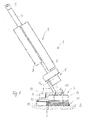
- a scouring-suction machine after the Fig. 1 to 16 represents a hand-held tillage implement in the context of the invention.
- the scouring-suction machine 1 is used for wet cleaning of floors in buildings.
- the scouring-suction machine 1 has a guide part 2 and a bottom part 3, which are connected to each other via a hinge assembly 9 described in more detail below.
- the guide part 2 is elongated and protrudes from the bottom part 3 from above.
- the guide part 2 comprises a central, dimensionally stable support tube 4, on the upper end region of which two handles 5 projecting to opposite sides are fastened. Between the handles 5 is a control block 22 (see Fig. 7 ), which is also firmly connected to the upper end face of the support tube 4.
- a suction drive 6 At a lower end portion of the support tube 4 is a suction drive 6 one below with reference to Fig. 5 attached suction system described in more detail.
- the suction drive 6 comprises an electrically operated suction turbine.
- the suction drive 6 forms the lower end of the guide part 2.
- the handles 5 with the control block 22 form the upper end of the guide part 2.
- a recovery tank 7 and a fresh water tank 8 are releasably attached. Both the dirty water tank 7 and the fresh water tank 8 are held by means of a quick-change system to the support tube 4 and can be removed without tools, replaced or attached to the support tube 4 again.
- the guide member 2 is pivotally connected via an upper hinge axis G 1 with the hinge assembly 9.
- the joint assembly 9 in turn is pivotally mounted by means of a lower hinge axis G 2 to the bottom part 3.
- the support tube 4 of the guide member 2 is coaxial with a vertical axis H 1 of the guide member 2 extends.
- the suction drive 6, which includes the electric suction turbine and a correspondingly dimensionally stable suction housing is fixed coaxially to the vertical axis H 1 at the lower end face of the support tube 4.
- the suction housing is a bearing component to which the hinge assembly 9 is articulated.
- the hinge assembly 9 comprises, as shown in FIG Fig. 2 can be seen, a dimensionally stable support web which is mounted pivotably about the lower hinge axis G 2 on the bottom part 3.
- the carrier web is connected via the upper joint axis G 1 pivotally connected to a support portion of the guide member 2, in particular with an extension of the support tube 4 or a support portion of the suction of the suction drive 6.
- the support web of the hinge assembly 9 extends in a plane parallel to a vertical axis H 1 receiving the pivot plane of the guide member 2, within which the guide member 2 according to Fig. 2 is mounted to pivot about the hinge axis G 1 on the support web of the joint assembly 9.
- the upper joint axis G 1 is aligned orthogonal to the vertical axis H 1 of the guide part 2.
- the lower joint axis G 2 is aligned orthogonal to the upper joint axis G 1 and orthogonal to the vertical axis H 1 , as long as the guide member 2 projects in a straight line extension to the support web of the hinge assembly 9 upwards.
- the hinge axis G 2 extends in the normal operating position of the bottom part 3 according to the Fig. 1 . 6, 7 parallel to a bottom B, on which the bottom part 3 rests in an operating position.
- Both the upper joint axis G 1 and the lower joint axis G 2 define pure pivot joints, each with two rotational degrees of freedom.
- the bottom part 3 is supported solely on the two tools 11 on the one hand and the Saugleistenan kann 12 on the other hand on the bottom B in the operating position of the scouring-suction machine 1. Since the guide member 2 is in turn supported on the bottom part 3 via the hinge assembly 9, the total weight of the scouring-suction machine 1 via a front support in the region of the support of the tools 11 on the bottom B and a rear support in the region of the support the sealing lips D supported on the bottom B.
- An attack region of the joint assembly 9 on the bottom part 3, by the lower hinge axis G 2 to the support bridge 10, is selected so as to provide a uniform weight distribution of the total weight of the scrubber-suction machine 1 on the front support in the area of the tools 11 and the rear support in the area of the squeegee assembly 12.
- a front-heavy weight distribution in the direction of the tools 11 can also be made.
- the scouring-suction machine 1 can be set up in a storage position, which defines a non-use position for the scouring-suction machine 1.
- the bottom part 3 is tilted over its front edge, which is defined by the leading edges of the rotatable tools 11, upwards.
- a support means in the form of a support roller 23 is arranged on which the bottom part 3 in the storage position according to Fig. 14 supported. The bottom part 3 is tilted so far that results in this storage position, a statically stable support on the front edge of the tools 11 on the one hand and the support roller 23 on the other hand.
- centrally arranged support roller 23 can also be provided a plurality of parallel spaced adjacent support rollers.
- the guide member 2 is pivoted for the non-use position corresponding storage position also relative to the erected bottom part 3 via a vertical out until securing means 25, 26 between the bottom part 3 and the guide member 2 to each other come into force fit.
- the guide part 2 is according to the embodiment Fig. 14 positioned in this position in an over-center position relative to the bottom part 3, so that the center of gravity of the guide part 2 is stably located above the bottom part 3.
- a permanent magnet 25 is provided on the guide part 2, which is assigned to the bottom part 3, a corresponding magnetizable surface 26.
- the permanent magnet 25 and the magnetizable surface 26 engage each other and cause a magnetic force limited securing the guide member 2 on the bottom part 3.
- the magnetic force protection can be easily by pivoting the guide member 2 to the Joint axis G 1 are repealed by the guide member 2 as shown in FIG Fig. 14 is orthogonally swung out of the plane. In this case, the mutually facing surfaces of the permanent magnet 25 and the magnetizable surface 26 slide laterally past each other. This movement is possible without much effort, since the magnetic force acts vertically between the adjacent surfaces of the magnetic security, but not parallel to this.
- the scouring-suction machine 1 in this in Fig. 14 illustrated securing position can also be transported in a simple manner by the scouring-suction machine 1 on the at least one support roller 23 manually tilted forward and then pulled or pushed over the handles 5.
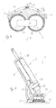
- the scouring suction machine 1a after the FIGS. 17 and 18 basically has the same structure as the previously based on the Fig. 1 to 16 Scouring suction machine described in detail 1. Functionally identical parts and sections are provided with the same reference numerals with the addition of the letter a.
- the disclosure of the embodiment according to the Fig. 1 to 16 directed. Significant difference in the scouring-suction machine 1a after the FIGS.
- a single, cylindrical rotatable tool 11a is provided, which is mounted in the operating position of the scouring-suction machine 1a aligned parallel to the bottom B axis of rotation in the bottom part 3a.
- the tool 11a is provided with a single, not shown electric rotary drive.
- the tool 11a can be driven in only one direction of rotation, in which for the bottom part 3a a permanent propulsion in the direction of arrow (see FIGS. 17 and 18 ) is achieved.
- the direction of rotation of the tool 11a is in Fig. 17 also represented by a circular arc-shaped arrow.
- a fresh water supply takes place in the region of the tool 11a analogous to the scouring-suction machine 1 after the Fig. 1 to 16 ,
- the suction of the wastewater liquor is carried out in the same manner in the Saugleistenan Aunt 12a by means of the suction and sealing lips Da, as previously described.
Abstract
2.1 Ein handgeführtes Bodenbearbeitungsgerät mit einem Bodenteil(3, 3a), der wenigstens ein auf einem Boden (B) mittels eines Antriebs rotierbares Werkzeug (11, 11a) umfasst, sowie mit einem Führungsteil (2, 2a), der wenigstens einen Handgriff (5) umfasst und mit dem Bodenteil (3, 3a) über eine Gelenkanordnung (9, 9a) verbunden ist, die derart gestaltet ist, dass der Führungsteil (2, 2a) ausgehend von einer Senkrechten umlaufend in allen Richtungen in Winkelstellungen relativ zur Senkrechten verschwenkbar ist und winkelbegrenzt in jeder Winkelstellung relativ zur Senkrechten drehmomentübertragend mit dem Bodenteil (3, 3a) in Wirkverbindung steht, ist bekannt. 2.2 Erfindungsgemäß ist das wenigstens eine rotierbare Werkzeug (11, 11a) derart am Bodenteil (3, 3a) angeordnet, dass im Betrieb des Bodenbearbeitungsgeräts das wenigstens eine rotierbare Werkzeug (11, 11a) einen permanenten linearen Vortrieb auf den Bodenteil (3, 3a) ausübt. 2.3 Einsatz als Nassreinigungsmaschinen2.1 A hand-held cultivator with a bottom part (3, 3a) comprising at least one on a bottom (B) by means of a drive rotatable tool (11, 11a), and with a guide part (2, 2a), the at least one handle (5 ) and is connected to the bottom part (3, 3a) via a hinge arrangement (9, 9a) designed such that the guide part (2, 2a), starting from a vertical, is pivotable circumferentially in all directions in angular positions relative to the vertical and angularly limited in each angular position relative to the vertical torque transmitting to the bottom part (3, 3a) is in operative connection, is known. 2.2 According to the invention, the at least one rotatable tool (11, 11a) is arranged on the bottom part (3, 3a) in such a way that during operation of the soil cultivating device the at least one rotatable tool (11, 11a) effects a permanent linear propulsion on the bottom part (3, 3a). exercises. 2.3 Use as wet cleaning machines
Description
Die Erfindung betrifft ein handgeführtes Bodenbearbeitungsgerät mit einem Bodenteil, der wenigstens ein auf einem Boden mittels eines Antriebs rotierbares Werkzeug umfasst, sowie mit einem Führungsteil, der wenigstens einen Handgriff umfasst und mit dem Bodenteil über eine Gelenkanordnung verbunden ist, die derart gestaltet ist, dass der Führungsteil ausgehend von einer Senkrechten umlaufend in allen Richtungen in Winkelstellungen relativ zur Senkrechten verschwenkbar ist und winkelbegrenzt in jeder Winkelstellung relativ zur Senkrechten drehmomentübertragend mit dem Bodenteil in Wirkverbindung steht.The invention relates to a handheld tillage implement with a bottom part comprising at least one tool rotatable on a floor by means of a drive, as well as with a guide part which comprises at least one handle and is connected to the bottom part via a hinge arrangement which is designed such that Guide part, starting from a vertical circumferentially in all directions in angular positions relative to the vertical pivot and angular limited in each angular position relative to the vertical torque-transmitting communicates with the bottom part in operative connection.
Ein derartiges Bodenbearbeitungsgerät ist aus der
Aufgabe der Erfindung ist es, ein Bodenbearbeitungsgerät der eingangs genannten Art zu schaffen, das eine weiter vereinfachte Bedienung gegenüber dem Stand der Technik ermöglicht.The object of the invention is to provide a harrow of the type mentioned, which allows a further simplified operation over the prior art.
Diese Aufgabe wird für ein Bodenbearbeitungsgerät der eingangs genannten Art dadurch gelöst, dass das wenigstens eine rotierbare Werkzeug derart am Bodenteil angeordnet ist, dass im Betrieb des Bodenbearbeitungsgeräts das wenigstens eine rotierbare Werkzeug einen permanenten linearen Vortrieb auf den Bodenteil ausübt. Das wenigstens eine Werkzeug ist ausschließlich in Vortriebsrichtung rotierbar. Eine Bedienperson muss das erfindungsgemäße Bodenbearbeitungsgerät daher nicht mehr in die entsprechende Bearbeitungsrichtung ziehen oder schieben, wie dies beim Stand der Technik der Fall ist. Vielmehr muss die Bedienperson lediglich noch eine Steuerung des sich selbsttätig fortbewegenden Bodenteils vornehmen. Durch die Gelenkanordnung ist ein besonders einfaches Steuern des Bodenbearbeitungsgeräts durch eine Bedienperson erzielbar, da eine einfache, manuell über den wenigstens einen Handgriff eingeleitete Drehbewegung auf das Führungsteil in jeder Winkelstellung des Führungsteils relativ zum Bodenteil eine entsprechende Drehmomentübertragung auf den Bodenteil gewährleistet, so dass die Richtung des Bodenteils über eine Steuerung des Führungsteils geändert werden kann. Dadurch ist ein äußerst geringer Kraftaufwand notwendig, um das Bodenbearbeitungsgerät zu steuern. Aufgrund der großen Beweglichkeit des Führungsteils relativ zum Bodenteil können zudem Fußböden auch in schwer zugänglichen Bereichen einfach bearbeitet werden. Die erfindungsgemäße Lösung ist sowohl für trocken arbeitende Bodenbearbeitungsgeräte als auch für nass arbeitende Bodenbearbeitungsgeräte vorgesehen. Als rotierbare Werkzeuge sind sowohl Werkzeuge mit etwa vertikal ausgerichteter Drehachse als auch Werkzeuge mit etwa horizontal ausgerichteter Drehachse vorgesehen. Erfindungswesentlich ist es, dass das wenigstens eine rotierbare Werkzeug relativ zum Bodenteil so angeordnet ist, dass sich im Betrieb ein linearer Vortrieb des Bodenteils durch das auf dem Boden rotierende Werkzeug ergibt. Dies bedeutet, dass der Bodenteil sich im Betrieb des wenigstens einen Werkzeugs permanent geradlinig nach vorne bewegt, solange kein Steuervorgang durch entsprechendes Verschwenken des Führungsteils eingeleitet wird. Falls wenigstens ein rotierbares Werkzeug in Form einer Walze oder Bürste vorgesehen ist, das mit horizontaler Drehachse im Bodenteil gelagert ist, bewirkt eine Rotation des wenigstens einen Werkzeugs in Vortriebsrichtung zwangsläufig eine lineare Vorwärtsbewegung des Bodenteils. Vorzugsweise ist ein einzelnes, bürsten- oder walzenförmiges Werkzeug vorgesehen. Alternativ können wenigstens zwei walzen- oder bürstenförmige Werkzeuge mit jeweils horizontaler Drehachse nebeneinander oder hintereinander angeordnet sein. Ein entsprechend linearer Vortrieb stellt sich bei dieser Alternative durch eine synchronisierte Antriebssteuerung der wenigstens zwei Werkzeuge ein. Bei hintereinander angeordneten Werkzeugen mit horizontaler Drehachse können diese auch gegenläufig rotieren, solange eine auf den Boden wirkende, resultierende Vortriebskraft für den Bodenteil erzielt wird. Insbesondere kann ein Werkzeug mit größerer Kraft oder höherer Drehzahl auf den Boden wirken als das andere Werkzeug, wobei das erste Werkzeug dann eine Rotation in Vortriebsrichtung haben muss. Bei Werkzeugen mit etwa vertikaler Drehachse sind wenigstens zwei gegenläufig zueinander drehbare Werkzeuge, insbesondere in Form von Tellern, vorgesehen, die gegenüber einer Horizontalebene geringfügig geneigt sind, um durch ungleiche Rotationsreibung jedes Tellers auf einem entsprechenden Boden die gewünschte lineare Vortriebsfunktion zu erzielen. Die beiden vorzugsweise tellerförmigen Werkzeuge sind vorteilhaft spiegelsymmetrisch zu einer vertikalen Mittellängsebene des Bodenteils um gleiche Winkelbeträge geneigt und werden mit synchronisierten Antriebsdrehzahlen gegenläufig angesteuert, um den gewünschten linearen Vortrieb zu erzielen.This object is achieved for a cultivator of the type mentioned above in that the at least one rotatable tool is arranged on the bottom part, that during operation of the harrow, the at least one rotatable Tool exerts a permanent linear propulsion on the bottom part. The at least one tool is rotatable exclusively in the direction of advance. An operator therefore no longer has to pull or push the soil cultivation device according to the invention into the corresponding processing direction, as is the case in the prior art. Rather, the operator only has to make a control of the self-propelled moving floor part. By the joint arrangement, a particularly simple control of the harrow by an operator can be achieved because a simple, initiated manually via the at least one rotary movement on the guide member in each angular position of the guide member relative to the bottom part ensures a corresponding torque transmission to the bottom part, so that the direction the bottom part can be changed via a control of the guide part. As a result, an extremely small amount of force is necessary to control the harrow. Due to the great flexibility of the guide part relative to the bottom part also floors can be easily edited even in hard to reach areas. The solution according to the invention is provided both for dry tillage equipment and for wet working tillage equipment. As a rotatable tools both tools are provided with approximately vertically oriented axis of rotation and tools with approximately horizontally oriented axis of rotation. It is essential to the invention that the at least one rotatable tool is arranged relative to the base part in such a way that, during operation, a linear advance of the base part results through the tool rotating on the floor. This means that the bottom part constantly moves in a straight line forward during the operation of the at least one tool, as long as no control process is initiated by corresponding pivoting of the guide member. If at least one rotatable tool in the form of a roller or brush is provided, which is mounted with a horizontal axis of rotation in the bottom part, causes a rotation of the at least one tool in the advancing direction inevitably a linear forward movement of the bottom part. Preferably, a single, brush or roller-shaped tool is provided. Alternatively, at least two roller or brush-shaped tools, each having a horizontal axis of rotation, can be arranged next to one another or one behind the other. A correspondingly linear propulsion arises in this alternative through a synchronized drive control of the at least two tools. In successively arranged tools with horizontal axis of rotation, these can also rotate in opposite directions, as long as acting on the ground, resulting driving force for the bottom part is achieved. In particular, a tool with greater force or higher speed can act on the ground than the other tool, the first tool then has to have a rotation in the advancing direction. In tools with an approximately vertical axis of rotation at least two oppositely rotatable tools, especially in the form of plates, are provided which are slightly inclined relative to a horizontal plane to achieve the desired linear propulsion function by unequal rotational friction of each plate on a corresponding ground. The two preferably dish-shaped tools are advantageous mirror-symmetrical inclined to a vertical central longitudinal plane of the bottom part by equal angular amounts and are driven in opposite directions with synchronized drive speeds to achieve the desired linear propulsion.
In Ausgestaltung der Erfindung ist das Bodenbearbeitungsgerät als Nassreinigungsmaschine, insbesondere als Scheuer-Saug-Maschine, ausgeführt, und weist eine - in Vortriebsrichtung gesehen - hinter dem rotierbaren Werkzeug angeordnete, im Betrieb auf dem Boden aufliegende Saugleistenanordnung auf. Die Saugleistenanordnung umfasst wenigstens eine über eine Bearbeitungsbreite des Bodenteils erstreckte und auf dem Boden aufliegende Dichtlippe. Vorzugsweise sind zwei im Wesentlichen parallel zueinander beabstandete Dichtlippen vorgesehen, zwischen denen eine entsprechende Saugwirkung durch wenigstens einen Saugstutzen eines Saugsystems der Nassreinigungsmaschine entsteht. Vorzugsweise ist die Saugleistenanordnung bogenförmig gekrümmt. Die Saugleistenanordnung kann auch mehrere neben- oder hintereinander angeordnete Saugleistenabschnitte umfassen. Erfindungsgemäß ist nur eine einzelne einoder mehrteilig ausgeführte Saugleistenanordnung vorgesehen, die hinter dem wenigstens einen rotierbaren Werkzeug angeordnet ist. Da das wenigstens eine rotierbare Werkzeug im Betrieb der Nassreinigungsmaschine einen permanenten linearen Vortrieb ausübt, ist gewährleistet, dass die gewünschte Reinigungswirkung permanent durch eine einfache, selbsttätige Vorwärtsbewegung des Bodenteils erzielt wird. Mittels des handgeführten Führungsteils wird der sich selbsttätig fortbewegende Bodenteil gesteuert. Bei der erfindungsgemäßen Nassreinigungsmaschine wird im Bereich des wenigstens einen rotierbaren Werkzeugs zunächst Frischwasser mit oder ohne Reinigungsadditiven zugeführt, das einen entsprechenden Scheuer- oder Schrubbvorgang durch das wenigstens eine rotierende Werkzeug unterstützt. Anschließend wird das erzeugte Schmutzwasser hinter dem wenigstens einen rotierenden Werkzeug durch die nachgeführte Saugleistenanordnung aufgesaugt und in einen Schmutzwassertank abgeführt.In an embodiment of the invention, the harrow is designed as a wet cleaning machine, in particular as a scouring-suction machine, and has a - seen in the advancing direction - behind the rotatable tool arranged, resting on the ground in operation Saugleistenanordnung. The Saugleistenanordnung comprises at least one extending over a processing width of the bottom part and resting on the floor sealing lip. Preferably, two substantially mutually parallel sealing lips are provided, between which a corresponding suction by at least one suction nozzle of a suction system of the wet cleaning machine is formed. Preferably, the Saugleistenanordnung is arcuately curved. The Saugleistenanordnung may also include a plurality of juxtaposed or successively arranged Saugleistenabschnitte. According to the invention, only a single or multiple-part designed Saugleistenanordnung is provided, which is arranged behind the at least one rotatable tool. Since the at least one rotatable tool during operation of the wet cleaning machine exerts a permanent linear propulsion, it is ensured that the desired cleaning effect is achieved permanently by a simple, automatic forward movement of the bottom part. By means of the hand-held guide part of the self-propelled moving floor part is controlled. In the wet cleaning machine according to the invention, first of all fresh water is supplied with or without cleaning additives in the area of the at least one rotatable tool, which first has a corresponding scouring or scrubbing operation through the supports at least one rotating tool. Subsequently, the generated dirty water is sucked up behind the at least one rotating tool by the tracked Saugleistenanordnung and discharged into a recovery tank.
In weiterer Ausgestaltung der Erfindung umfasst die Gelenkanordnung wenigstens zwei zueinander verschiedene, insbesondere zueinander orthogonale, Gelenkachsen, die jeweils zu einer Hochachse des Führungsteils verschieden, insbesondere orthogonal, ausgerichtet sind. Unter der Hochachse des Führungsteils ist eine Mittellängsachse in Längserstreckung des Führungsteils zu verstehen, die bei relativ zu einem Boden und relativ zum Bodenteil senkrechter Ausrichtung des Führungsteils in Hochrichtung des Bodenbearbeitungsgeräts erstreckt ist. Vorteilhaft sind die beiden Gelenkachsen orthogonal zueinander ausgerichtet. Um zu gewährleisten, dass in jeder Winkelstellung des Führungsteils relativ zur Senkrechten eine Drehmomentübertragung auf den Bodenteil ausgeübt werden kann, müssen die Gelenkachsen auch zur Hochachse des Führungsteils verschieden, insbesondere orthogonal, ausgerichtet sein. Hierdurch ist gewährleistet, dass bei einer Drehbewegung des Führungsteils um seine Hochachse, die manuell eingeleitet wird, in jeder Winkelstellung des Führungsteils relativ zum Bodenteil ein Drehmoment auf den Bodenteil übertragen wird. Die Möglichkeit der Drehmomentübertragung des Führungsteils auf den Bodenteil ist auf Winkelstellungen des Führungsteils relativ zur Senkrechten von weniger als 45 bis 50° begrenzt. Die Gelenkachsen können real vorhanden sein durch entsprechende mechanische Gelenkgestaltungen. Alternativ können die Gelenkachsen auch virtuell oder imaginär innerhalb wenigstens eines entsprechenden Festkörpergelenks vorgesehen sein, das die Gelenkanordnung bildet.In a further embodiment of the invention, the joint arrangement comprises at least two mutually different, in particular mutually orthogonal, hinge axes which are each different to a vertical axis of the guide member, in particular orthogonal, aligned. The vertical axis of the guide part is to be understood as meaning a central longitudinal axis in the longitudinal extent of the guide part which extends in the vertical direction of the tillage device when the guide part is oriented vertically relative to a floor and relative to the floor part. Advantageously, the two hinge axes are aligned orthogonal to each other. In order to ensure that in each angular position of the guide member relative to the vertical torque transmission can be exerted on the bottom part, the hinge axes must also different to the vertical axis of the guide member, in particular orthogonal aligned. This ensures that in a rotational movement of the guide member about its vertical axis, which is initiated manually, in each angular position of the guide member relative to the bottom part of a torque is transmitted to the bottom part. The possibility of torque transmission of the guide member to the bottom part is limited to angular positions of the guide member relative to the vertical of less than 45 to 50 °. The joint axes can be present in real terms by corresponding mechanical joint designs. Alternatively, the hinge axes may also be provided virtually or imaginarily within at least one corresponding solid-body joint forming the hinge assembly.
In weiterer Ausgestaltung der Erfindung sind die wenigstens zwei Gelenkachsen in Richtung der Hochachse des Führungsteils zueinander beabstandet. In weiterer Ausgestaltung ist eine Gewichtsverteilung des Führungsteils zu der oberen Gelenkachse hin nach unten verlagert. Vorteilhaft ist ein Massenschwerpunkt des Führungsteils in betriebsbereitem Zustand im Bereich einer oberen Gelenkachse oder unterhalb der oberen Gelenkachse angeordnet. Ein betriebsbereiter Zustand liegt vor, wenn die Scheuersaugmaschine mit Frischwasser (Reinigungswasser) betriebsbereit gefüllt ist und der Führungsteil sich in einer aufrechten Betriebsstellung (in einem Winkel zwischen 0° und 45° zu einer Senkrechten) befindet. Eine Gewichtsverteilung entsprechender Komponenten innerhalb des Führungsteils ist so gestaltet, dass der Massenschwerpunkt des Führungsteils sich in einer unteren Hälfte des Führungsteils befindet - auf eine gesamte Längserstreckung des Führungsteils bezogen. Durch die Verlagerung des Massenschwerpunkts in die untere Hälfte des Führungsteils ist eine Abstützung eines Großteils der Gewichtskraft des Führungsteils im Bereich der Gelenkanordnung ermöglicht. Dadurch wird im oberen Bereich des Führungsteils, der den wenigstens einen Handgriff umfasst, durch eine Bedienperson eine wesentlich geringere Haltekraft für den Führungsteil benötigt als dies der Fall wäre, wenn eine Gewichtsverteilung des Führungsteils weiter nach oben verlagert wäre.In a further embodiment of the invention, the at least two hinge axes are spaced apart in the direction of the vertical axis of the guide part. In a further embodiment, a weight distribution of the guide part is displaced down to the upper hinge axis. Advantageously, a center of gravity of the guide part is arranged in the ready state in the region of an upper hinge axis or below the upper hinge axis. A ready state is when the scrubber is filled with fresh water (cleaning water) ready for use and the guide member in an upright operating position (at an angle between 0 ° and 45 ° to a vertical). A weight distribution of corresponding components within the guide member is designed so that the center of mass of the guide member is located in a lower half of the guide member - based on an entire longitudinal extension of the guide member. Due to the displacement of the center of gravity in the lower half of the guide part, a support of a large part of the weight of the guide part in the region of the joint arrangement is made possible. As a result, in the upper region of the guide part, which comprises the at least one handle, a considerably smaller holding force for the guide part is required by an operator than would be the case if a weight distribution of the guide part were further displaced upwards.
In weiterer Ausgestaltung der Erfindung flankiert ein unterer Funktionsabschnitt des Führungsteils die Gelenkanordnung zumindest teilweise. Vorteilhaft ist der untere Funktionsabschnitt - in Vortriebsrichtung gesehen - vor der Gelenkanordnung positioniert, so dass bei entsprechender Schrägstellung des Führungsteils nach hinten der Funktionsabschnitt im Bereich der oberen Gelenkachse abgestützt ist. Die Handhabbarkeit des Bodenbearbeitungsgerätes für eine Bedienperson wird hierdurch weiter verbessert. Ein entsprechender Funktionsabschnitt kann ein Frisch- und/oder Schmutzwassertank sein, die in befülltem Zustand ein relativ großes Gewicht aufweisen. Alternativ ist gemäß einer weiteren Ausgestaltung vorgesehen, einen Saugantrieb für die Saugleistenanordnung, insbesondere eine Saugturbine, als unteren Funktionsabschnitt des Führungsteils vorzusehen. Auch der Saugantrieb weist ein relativ großes Gewicht auf, so dass sich durch die Anordnung des Saugantriebs im unteren Bereich des Führungsteils ebenfalls eine zur Gelenkanordnung hin verlagerte Gewichtsverteilung ergibt. Die Verlagerung des Saugantriebs in den Führungsteil hinein ermöglicht zudem eine vereinfachte Gestaltung des Bodenteils, dem dann im Wesentlichen nur noch das wenigstens eine rotierbare Werkzeug, ein zugehöriger Rotationsantrieb sowie die Saugleistenanordnung zugeordnet sind.In a further embodiment of the invention, a lower functional portion of the guide member flanking the hinge assembly at least partially. Advantageously, the lower functional portion - as seen in the advancing direction - positioned in front of the hinge assembly, so that is supported at a corresponding inclination of the guide member to the rear of the functional portion in the region of the upper hinge axis. The handling of the soil cultivation device for an operator is thereby further improved. A corresponding functional section may be a fresh and / or dirty water tank, which have a relatively large weight in the filled state. Alternatively, it is provided according to a further embodiment, to provide a suction drive for the Saugleistenanordnung, in particular a suction turbine, as a lower functional portion of the guide member. Also, the suction drive has a relatively large weight, so that also results from the arrangement of the suction drive in the lower region of the guide part shifted to the hinge assembly weight distribution. The displacement of the suction drive in the guide part also allows a simplified design of the bottom part, which then essentially only the at least one rotatable tool, an associated rotary drive and the Saugleistenanordnung are assigned.
In weiterer Ausgestaltung der Erfindung ist der Bodenteil - in Vortriebsrichtung gesehen, vorne über das wenigstens eine rotierbare Werkzeug und hinten über die Saugleistenanordnung in normaler Betriebsposition auf dem Boden abgestützt, und die Gelenkanordnung ist in einem Angriffsbereich an dem Bodenteil derart angelenkt, dass sich eine gleichmäßige oder frontlastige Verteilung eines Gesamtgewichts des Bodenbearbeitungsgeräts auf die vordere und die hintere Abstützung des Bodenteils auf dem Boden ergibt. Die Gelenkanordnung greift demzufolge an einer Stelle am Bodenteil an, die die Gewichtskraft des Führungsteils so auf dem Bodenteil einleitet, dass sich eine definierte Verteilung des Gesamtgewichts des Bodenbearbeitungsgeräts auf die vordere Abstützung im Bereich des wenigstens einen rotierbaren Werkzeugs einerseits und auf die hintere Abstützung im Bereich der Saugleistenanordnung andererseits ergibt. Eine gleichmäßige Gewichtsverteilung bedeutet, dass eine zumindest weitgehend hälftige Verteilung auf die vordere und die hintere Abstützung erfolgt. Eine frontlastige Gewichtsverteilung bedeutet, dass im Bereich des wenigstens einen rotierbaren Werkzeugs eine Abstützung von mehr als 55% bis hin zu maximal 90% des Gesamtgewichts erfolgt. Durch die beschriebenen Verteilungsverhältnisse ist eine gute Reinigungskraft durch das wenigstens eine rotierbare Werkzeug gewährleistet. Für die Abstützung des Bodenteils auf dem Boden sind lediglich das wenigstens eine rotierbare Werkzeug und die Saugleistenanordnung notwendig.In a further embodiment of the invention, the bottom part - seen in the forward drive direction, the front supported on the at least one rotatable tool and the rear of the Saugleistenanordnung in normal operating position on the ground, and the hinge assembly is articulated in an attack area on the bottom part such that a uniform or front-heavy distribution of a total weight of the harrow on the front and the rear support of the bottom part results on the ground. The joint assembly thus attacks at a point on the bottom part, which initiates the weight of the guide member on the bottom part, that a defined distribution of the total weight of the harrow on the front support in the region of at least one rotatable tool on the one hand and on the rear support in the area the Saugleistenanordnung other hand. A uniform weight distribution means that an at least largely equal distribution takes place on the front and the rear support. A front-weighted weight distribution means that in the area of the at least one rotatable tool a support of more than 55% up to a maximum of 90% of the total weight takes place. Due to the described distribution ratios a good cleaning power is ensured by the at least one rotatable tool. For the support of the bottom part on the ground only the at least one rotatable tool and the Saugleistenanordnung are necessary.
In weiterer Ausgestaltung der Erfindung ist der Saugleistenanordnung wenigstens ein insbesondere roll- oder gleitbeweglicher Bodenabstandshalter zugeordnet, der ergänzend zu wenigstens einer Dichtlippe der Saugleistenanordnung eine Abstützung des Bodenteils auf dem Boden bewirkt. Der Bodenabstandshalter gewährleistet, dass bei der Auflage auf einem Boden eine Biegung der wenigstens einen Dichtlippe begrenzt ist. Die Dichtlippe ist hierdurch definiert immer um einen gleichen Winkel gekrümmt, wodurch sich eine besonders gute Dichtwirkung unabhängig von der Beschaffenheit einer Bodenoberfläche ergibt. Dadurch ist gewährleistet, dass die wenigstens eine Dichtlippe keinem vorzeitigem Verschleiß durch Überlastung unterliegt. Zudem ist gewährleistet, dass die Dichtlippe sich nicht zu stark durchbiegt. Als Bodenabstandshalter können mehrere über die Erstreckung der Saugleistenanordnung vorgesehene Roll-oder Gleitelemente vorgesehen sein. Alternativ kann eine vordere Dichtlippe der Saugleistenanordnung steifer gestaltet sein und so die Funktion eines Bodenabstandshalters übernehmen, der vor der eigentlichen Dichtlippe auf dem Boden entlanggleitet. Diese vordere Dichtlippe biegt sich nicht durch, sondern ist in Hochrichtung steif. In besonders vorteilhafter Weise ist der wenigstens eine Bodenabstandshalter höhenverstellbar angeordnet. Dadurch kann die Anpressfläche der wenigstens einen Dichtlippe auf dem Boden verändert werden.In a further embodiment of the invention, the Saugleistenanordnung is associated with at least one particular rollable or slidable floor spacer, which causes a supplement of at least one sealing lip of the Saugleistenanordnung a support of the bottom part on the floor. The bottom spacer ensures that when resting on a floor, a bend of the at least one sealing lip is limited. The sealing lip is thereby defined always curved by an equal angle, resulting in a particularly good sealing effect regardless of the nature of a soil surface. This ensures that the at least one sealing lip is not subject to premature wear due to overloading. In addition, it is ensured that the sealing lip does not bend too much. As a floor spacer several provided over the extension of the Saugleistenanordnung rolling or sliding elements can be provided. Alternatively, a front sealing lip of the Saugleistenanordnung be designed stiffer and so take over the function of a floor spacer, which slides along the floor in front of the actual sealing lip. This front sealing lip does not bend through, but is stiff in the vertical direction. In a particularly advantageous manner, the at least one bottom spacer is arranged vertically adjustable. As a result, the contact surface of the at least one sealing lip on the floor can be changed.
In weiterer Ausgestaltung der Erfindung ist der Angriffsbereich der Gelenkanordnung am Bodenteil in Vortriebsrichtung des Bodenteils nach vorne oder nach hinten verstellbar. Dadurch ist es möglich, die Gewichtsverteilung auf die vordere und hintere Abstützung des Bodenteils zum Boden hin zu variieren.In a further embodiment of the invention, the engagement region of the joint arrangement on the bottom part in the advancing direction of the bottom part forward or backward adjustable. This makes it possible to vary the weight distribution on the front and rear support of the bottom part to the ground.
In weiterer Ausgestaltung der Erfindung umfasst der Bodenteil eine sich längs der Vortriebsrichtung des Bodenteils erstreckende Trägerbrücke, an der der Angriffsbereich der Gelenkanordnung vorgesehen ist, und die um jeweils eine quer zur Vortriebsrichtung und parallel zum Boden erstreckte Schwenkachse an der Saugleistenanordnung einerseits und im Bereich einer Lagerung des wenigstens einen rotierbaren Werkzeugs andererseits gelenkig gelagert ist. Die Trägerbrücke stützt sich an wenigstens zwei symmetrisch zu einer vertikalen Mittellängsebene ausgerichteten Stützpunkten auf der Saugleistenanordnung ab. Durch diese Ausgestaltung sind die Saugleistenanordnung und die Lagerung, insbesondere ein Gehäuse, für das wenigstens eine rotierende Werkzeug nicht starr miteinander verbunden, sondern gelenkig zueinander gekoppelt. Eine Veränderung der Abstützung im Bereich des wenigstens einen rotierbaren Werkzeugs, insbesondere durch Abnützung des Werkzeugs, hat daher keinen Einfluss auf die hintere Abstützung im Bereich der Saugleistenanordnung und demzufolge auch keinen Einfluss auf eine Veränderung der Lage der Saugleistenanordnung. Entsprechend umgekehrt führt ein Absenken der Saugleistenanordnung im Laufe des Betriebs der Nassreinigungsmaschine nicht zu einem zwangsläufigen Anheben oder Kippen des rotierbaren Werkzeugs im Bereich der vorderen Abstützung. Denn durch die beschriebenen Schwenkachsen, die parallel zueinander verlaufen, ergibt sich insoweit eine statische Abkopplung der beiden Abstützungen des Bodenteils zum Boden hin voneinander. Hierdurch ist gewährleistet, dass Kipp- und Neigebewegungen des Führungsteiles, die durch die Bedienperson eingeleitet werden, keinen Einfluss auf die Lage der Saugleistenanordnung haben. Die Saug- und Dichtwirkung der Saugleistenanordnung bleibt daher immer gleich. Die Trägerbrücke trägt neben dem Führungsteil, das über die Gelenkanordnung an der Trägerbrücke abgestützt ist, bei einem elektromotorischen Antrieb für das wenigstens eine rotierbare Werkzeug sowie einem elektromotorischen Saugantrieb des Saugsystems auch wenigstens einen Energiespeicher, vorzugsweise in Form eines Akkumulators, besonders vorteilhaft in Form eines Lithium-Ionen-Akkumulators. Das Gewicht eines entsprechenden Akkumulators erhöht einen Druck auf die Saugleistenanordnung und verbessert deren Saug- und Dichtwirkung.In a further embodiment of the invention, the bottom part comprises a carrier bridge extending along the direction of advance of the bottom part, on which the engagement region of the joint arrangement is provided and which extends around a respective transverse to the direction of advance and parallel to the ground pivot axis on the Saugleistenanordnung one hand and in the region of storage the at least one rotatable tool on the other hand is articulated. The support bridge is supported on at least two symmetrically aligned to a vertical central longitudinal plane points on the Saugleistenanordnung. By this configuration, the Saugleistenanordnung and the storage, in particular a housing for which at least one rotating tool is not rigidly connected to each other, but coupled to each other articulated. A change in the support in the region of the at least one rotatable tool, in particular due to wear of the tool, therefore has no influence on the rear support in the region of the Saugleistenanordnung and consequently also has no influence on a change in the position of the Saugleistenanordnung. Conversely, lowering the squeegee assembly in the course of operation of the wet cleaning machine does not result in inevitable lifting or tilting of the rotatable tool in the area of the front support. Because by the pivot axes described, which are parallel to each other, this results in a static decoupling of the two supports of the bottom part to the ground from each other. This ensures that tilting and tilting movements of the guide part, which are initiated by the operator, have no influence on the position of the Saugleistenanordnung. The suction and sealing effect of the Saugleistenanordnung therefore always remains the same. The support bridge carries next to the guide part, which is supported on the hinge assembly on the support bridge, in an electric motor drive for the at least one rotatable tool and an electromotive Suction drive of the suction system and at least one energy storage, preferably in the form of a rechargeable battery, particularly advantageous in the form of a lithium-ion battery. The weight of a corresponding accumulator increases pressure on the Saugleistenanordnung and improves its suction and sealing effect.
In weiterer Ausgestaltung der Erfindung ist ein einem Saugsystem für die Saugleistenanordnung zugeordneter Strömungskanal im Führungsteil koaxial oder parallel zu der Hochachse des Führungsteils angeordnet. Die Idee dieser Ausgestaltung ist es, den Führungsteil so kompakt wie möglich zu gestalten und gewichtsoptimiert um die Hochachse des Führungsteils zu verteilen. Die Verlegung des Strömungskanals im Bereich der Hochachse des Führungsteils ermöglicht eine platzsparende Bauweise. Der Strömungskanal kann durch einen flexiblen Schlauch oder ein formstabiles Rohr gebildet sein.In a further embodiment of the invention, a suction system for a Saugleistenanordnung associated flow channel in the guide member is arranged coaxially or parallel to the vertical axis of the guide member. The idea of this embodiment is to make the guide part as compact as possible and weight-optimized to distribute around the vertical axis of the guide member. The laying of the flow channel in the region of the vertical axis of the guide part allows a space-saving design. The flow channel can be formed by a flexible hose or a dimensionally stable tube.
In weiterer Ausgestaltung der Erfindung umfasst der Führungsteil ein längs der Hochachse erstrecktes Tragrohr, in dem der Strömungskanal integriert ist. Das Tragrohr weist eine Doppelfunktion auf, indem es zum einen als Träger für die weiteren Funktionskomponenten des Führungsteils dient. Zum anderen bildet es den Strömungskanal des Saugsystems. In dem Tragrohr können auch mehrere Strömungskanäle des Saugsystems und/oder eines Frischwasserzuführsystems verlaufen. Zudem kann wenigstens ein Kabelkanal in dem Tragrohr integriert sein, insbesondere durch Koextrusion. In diesem Kabelkanal können Steuer- und Stromversorgungskabel verlegt sein.In a further embodiment of the invention, the guide part comprises a longitudinal axis extending along the support tube, in which the flow channel is integrated. The support tube has a dual function by serving as a support for the other functional components of the guide part. On the other hand, it forms the flow channel of the suction system. In the support tube and a plurality of flow channels of the suction system and / or a Frischwasserzuführsystems can run. In addition, at least one cable channel can be integrated in the support tube, in particular by coextrusion. In this cable channel control and power supply cables may be misplaced.
In weiterer Ausgestaltung der Erfindung ist der Saugantrieb an einem unteren Endbereich des Tragrohrs angeordnet. Vorzugsweise ist der Saugantrieb als elektrische Saugturbine gestaltet, die koaxial am unteren Endbereich des Tragrohrs befestigt ist und direkt mit dem im Tragrohr verlaufenden Strömungskanal in Wirkverbindung steht. Hierdurch ergibt sich ein kurzer Saugweg für die Saugturbine, so dass lediglich geringe Saugverluste auftreten. Hierdurch ist ein geringerer Energieverbrauch gewährleistet, der einen kleinen und gewichtssparenden Akkumulator ermöglicht.In a further embodiment of the invention, the suction drive is arranged at a lower end region of the support tube. Preferably, the suction drive is designed as an electric suction turbine, which is coaxially fixed to the lower end portion of the support tube and is directly connected to the running in the support tube flow channel in operative connection. This results in a short suction path for the suction turbine, so that only small suction losses occur. As a result, a lower energy consumption is ensured, which allows a small and weight-saving accumulator.
In weiterer Ausgestaltung der Erfindung sind Frisch- und Schmutzwassertanks des Saugsystems längserstreckt gestaltet und flankieren das Tragrohr auf gegenüberliegenden Seiten. Dadurch sind auch die Frisch- und Schmutzwassertanks direkt um die Hochachse des Führungsteils herum gruppiert. Durch die Verteilung der Frisch- und Schmutzwassertanks auf gegenüberliegenden Seiten des Tragrohrs ergibt sich eine besonders gute Gewichtsverteilung beidseitig der Hochachse des Führungsteils, was die Handhabung des Führungsteils durch eine Bedienperson erheblich vereinfacht. Unter Frischwasser ist Reinigungswasser zu verstehen, das dem wenigstens einen Werkzeug zugeführt wird und inbesondere aus Wasser und Reinigungsadditiven oder als anders ausgeführte Reinigungslösung gestaltet sein kann.In a further embodiment of the invention, fresh and dirty water tanks of the suction system are designed elongated and flank the support tube on opposite sides Pages. As a result, the fresh and dirty water tanks are grouped directly around the vertical axis of the guide part. The distribution of the fresh and dirty water tanks on opposite sides of the support tube results in a particularly good weight distribution on both sides of the vertical axis of the guide part, which greatly simplifies the handling of the guide member by an operator. Under fresh water cleaning water is to be understood, which is supplied to the at least one tool and can be designed in particular from water and cleaning additives or as a different running cleaning solution.
In vorteilhafter Weise ist der Saugantrieb - in Vortriebsrichtung des Bodenteils gesehen - vor der Gelenkanordnung positioniert, so dass bei normaler Geradeaus-Stellung der Nassreinigungsmaschine der Führungsteil schräg nach hinten gestellt ist und die Bedienperson hinter dem Bodenteil läuft. In dieser Stellung stützt sich das Gewicht des Führungsteils, insbesondere des Saugantriebs, im Bereich der oberen Gelenkachse der Gelenkanordnung ab, so dass eine Halte- und Führungskraft im Bereich des Handgriffs des Führungsteils für eine entsprechende Bedienperson äußerst gering ist. Dies ermöglicht eine einfache und kraftsparende Handhabung der Nassreinigungsmaschine in ihrem Betriebszustand.Advantageously, the suction drive - as seen in the advancing direction of the bottom part - positioned in front of the hinge assembly, so that in normal straight-ahead position of the wet cleaning machine, the guide member is placed obliquely backwards and the operator runs behind the bottom part. In this position, the weight of the guide part, in particular of the suction drive, is supported in the region of the upper hinge axis of the hinge arrangement, so that a holding and guiding force in the region of the handle of the guide part for a corresponding operator is extremely low. This allows a simple and energy-saving handling of the wet cleaning machine in its operating state.
In weiterer Ausgestaltung der Erfindung ist am Bodenteil wenigstens ein Stützmittel vorgesehen, das den Bodenteil in einer gekippten Transport- oder Lagerstellung statisch bestimmt auf dem Boden abstützt. Dadurch kann das Bodenbearbeitungsgerät in nicht benötigtem Ruhezustand platzsparend verstaut werden. Eine solche Parkposition gewährleistet auch eine Entlastung des wenigstens einen Werkzeugs und der Saugleistenanordnung, wodurch sich ein geringer Verschleiß ergibt.In a further embodiment of the invention, at least one support means is provided on the bottom part, which supports the bottom part in a tilted transport or storage position statically determined on the ground. As a result, the tillage implement can be stowed to save space in not required rest state. Such a parking position also ensures relief of the at least one tool and the Saugleistenanordnung, resulting in a low wear.
In weiterer Ausgestaltung der Erfindung ist das wenigstens eine Stützmittel als gleit-oder rollbewegliches Stützelement gestaltet. Neben der Stützung und Sicherung im nicht benötigten Ruhezustand (Lagerstellung) dient das wenigstens eine gleit- oder rollbewegliche Stützelement daher auch zum Transport des Bodenbearbeitungsgeräts, wenn sich dieses nicht in seinem Betriebszustand befindet.In a further embodiment of the invention, the at least one support means is designed as a sliding or roll-movable support element. In addition to the support and backup in the unneeded rest state (storage position), the at least one sliding or rolling movable support element therefore also serves to transport the harrow, if this is not in its operating state.
In weiterer Ausgestaltung der Erfindung ist der Führungsteil am Bodenteil in der Transport- oder Lagerstellung des Bodenteils mittels wenigstens eines Sicherungsmittels in einer Ruhestellung kraftbegrenzt gesichert, in der insbesondere der Führungsteil und der Bodenteil in einer Übertotpunktlage relativ zueinander statisch bestimmt abgestützt sind. Durch diese Ausgestaltung ist es möglich, den Führungsteil in eine definierte Ruhestellung relativ zum Bodenteil zu überführen. Die kraftbegrenzte Sicherung mittels des Sicherungsmittels gewährleistet, dass der Führungsteil vom Bodenteil in einfacher Weise und mit geringem Kraftaufwand wieder gelöst werden kann, um den Bodenteil und den Führungsteil in die Betriebsstellung zu überführen. In vorteilhafter Weise sind in der Ruhestellung des Bodenbearbeitungsgeräts der Führungsteil und der Bodenteil in einer Übertotpunktlage relativ zueinander statisch bestimmt abgestützt. Dies bedeutet, dass der Führungsteil über die wenigstens eine Gelenkachse der Gelenkanordnung relativ zum Bodenteil so weit über dem Bodenteil verschwenkt ist, dass der Massenschwerpunkt des Führungsteils oberhalb des Bodenteils positioniert ist.In a further embodiment of the invention, the guide member on the bottom part in the transport or storage position of the bottom part by means of at least one securing means in a rest position secured by force, in particular the guide member and the bottom part are supported statically determined in an over-center position relative to each other. By this configuration, it is possible to transfer the guide member in a defined rest position relative to the bottom part. The force-limited securing means of the securing means ensures that the guide member can be released from the bottom part in a simple manner and with little effort again to transfer the bottom part and the guide member in the operating position. In an advantageous manner, in the rest position of the cultivator, the guide part and the bottom part are statically supported in an over-center position relative to each other. This means that the guide part over the at least one hinge axis of the joint assembly is pivoted relative to the bottom part so far above the bottom part, that the center of mass of the guide member is positioned above the bottom part.
In weiterer Ausgestaltung der Erfindung ist das wenigstens eine Sicherungsmittel kraftoder formschlüssig wirksam. Das wenigstens eine Sicherungsmittel kann mechanisch kraft- oder formschlüssig wirksam sein. Alternativ ist es vorgesehen, dass der Kraftschluss durch das wenigstens eine Sicherungsmittel durch Magnetkraft erzeugt wird. Ein mechanisch kraft- oder formschlüssig wirksames Sicherungsmittel kann durch eine lösbare Rastverbindung, durch einen Klettverschluss oder einen anders gestalteten Haftverschluss ausgeführt sein. Bei einer kraftschlüssigen Wirkung des Sicherungsmittels durch Magnetkraft ist vorzugsweise am Führungsteil oder am Bodenteil ein Permanentmagnet vorgesehen, dem als entsprechendes Gegenstück am Bodenteil oder am Führungsteil eine magnetisierbare Fläche, insbesondere eine metallische Fläche, entgegengesetzt ist. Der Vorteil eines als Magnetsicherung gestalteten Sicherungsmittels ist es, dass die Magnetkräfte in Richtung entsprechender Magnetfeldlinien relativ hoch sind, bei einer Bewegung des Führungsteils relativ zum Bodenteil quer zu diesen Magnetfeldlinien hingegen ein einfaches Lösen der Magnetsicherung mit geringer Kraft erfolgen kann.In a further embodiment of the invention, the at least one securing means is positively or positively effective. The at least one securing means can be mechanically non-positively or positively effective. Alternatively, it is provided that the frictional connection is generated by the at least one securing means by magnetic force. A mechanically force-locking or form-locking effective securing means can be implemented by a releasable latching connection, by a hook-and-loop fastener or a differently designed adhesive fastener. In a non-positive effect of the securing means by magnetic force, a permanent magnet is preferably provided on the guide part or on the bottom part, which is opposite to a corresponding counterpart on the bottom part or on the guide part, a magnetizable surface, in particular a metallic surface. The advantage of a securing means designed as a magnetic security is that the magnetic forces in the direction of corresponding magnetic field lines are relatively high, with a movement of the guide member relative to the bottom part transverse to these magnetic field lines, however, a simple release of the magnetic fuse can be done with little force.
Die Erfindung betrifft auch ein Bodenbearbeitungssystem mit einem handgeführten Bodenbearbeitungsgerät, wie es zuvor beschrieben wurde, sowie mit einem Vorratswagen, der wenigstens einen austauschbaren und befüllten Frischwassertank sowie wenigstens eine Aufnahme für einen befüllten Schmutzwassertank oder/und ein Schmutzwasseraufnahmebehältnis aufweist, dessen Volumen wenigstens dem Doppelten eines Schmutzwassertankvolumens entspricht. Zudem kann der Vorratswagen ergänzend auch noch wenigstens einen Akkumulator vorhalten, so dass bei Bedarf ein Austausch des Akkumulators an der Scheuersaugmaschine ohne großen Aufwand erfolgen kann. Dadurch ist es möglich, auch größere Bodenflächen zeit- und kostensparend zu bearbeiten. Durch den Vorratswagen ist es möglich, das Volumen der Frisch- und Schmutzwassertanks der Nassreinigungsmaschine gering zu halten, um so eine einfache und kraftsparende Bedienung durch eine Bedienperson zu ermöglichen. Dadurch, dass auf dem Vorratswagen wenigstens ein, vorzugsweise mehrere Frischwassertanks befüllt vorgehalten sind, kann ein schneller Austausch erfolgen. Der Vorratswagen wird vorzugsweise in der Nähe des Bodenbearbeitungsgeräts während eines entsprechenden Betriebszeitraums positioniert oder mitgeführt, so dass auch ein einfaches Entleeren oder Austauschen eines Schmutzwassertanks erfolgen kann, ohne dass ein entsprechender Leerungs- oder Austauschvorgang an einer stationären Stelle eines entsprechenden Gebäudes erfolgen muss, in dem die Bodenbearbeitung vorgenommen wird. Der Vorratswagen kann auch mit einer Halterung zum Aufnehmen oder Anhängen der Scheuersaugmaschine versehen sein, so dass die Scheuersaugmaschine auf oder an dem Vorratswagen transportiert werden kann.The invention also relates to a soil cultivation system with a hand-held soil cultivating device, as described above, as well as with a storage trolley, the at least one replaceable and filled fresh water tank and at least one receptacle for a filled waste water tank and / or a dirty water receptacle whose volume corresponds to at least twice the volume of a waste water tank. In addition, the storage trolley complementarily also hold at least one accumulator, so that if necessary, an exchange of the accumulator can be done on the scrubber without much effort. This makes it possible to work even larger floor space saving time and money. Through the storage trolley, it is possible to keep the volume of fresh and dirty water tanks of the wet cleaning machine low, so as to allow a simple and energy-saving operation by an operator. Due to the fact that at least one, preferably a plurality of fresh water tanks are kept in stock on the supply truck, a quick exchange can take place. The storage trolley is preferably positioned or carried in the vicinity of the harrow during a corresponding period of operation, so that a simple emptying or replacement of a dirty water tank can take place without a corresponding emptying or replacement process must take place at a stationary location of a corresponding building, in the the tillage is done. The storage trolley can also be provided with a holder for receiving or attaching the scrubber, so that the scrubber can be transported on or on the storage trolley.
Weitere Vorteile und Merkmale der Erfindung ergeben sich aus den Ansprüchen sowie aus der nachfolgenden Beschreibung bevorzugter Ausführungsbeispiele der Erfindung, die anhand der Zeichnungen dargestellt sind.
- Fig. 1
- zeigt schematisch eine Ausführungsform eines erfindungsgemäßen, handgeführten Bodenbearbeitungsgeräts in Form einer Scheuer-Saug-Maschine,
- Fig. 2
- schematisch die Scheuer-Saug-Maschine nach
Fig. 1 in einer Ansicht schräg von hinten und von unten, - Fig. 3
- schematisch in einer Frontansicht einen Bodenteil der Scheuer-Saug-Maschine nach den
Fig. 1 und 2 , - Fig. 4
- in einer schematischen Draufsicht von oben den Bodenteil nach
Fig. 3 , - Fig. 5
- die Scheuer-Saug-Maschine nach
Fig. 1 mit ergänzender schematischer Darstellung eines Saugsystems zum Zuführen von Frischwasser und Abführen von Schmutzwasser, - Fig. 6
- schematisch eine weitere Ansicht der Scheuer-Saug-Maschine nach
Fig. 1 unter Weglassung von Frisch- und Schmutzwassertanks, - Fig. 7
- die Scheuer-Saug-Maschine nach
Fig. 6 in einer weiteren Betriebsstellung, - Fig. 8
- schematisch die Scheuer-Saug-Maschine nach den
Fig. 6 und 7 in einer Betriebsposition auf einem Boden unterhalb eines Tisches, - Fig. 9
bis 13 - unterschiedliche Betriebspositionen der Scheuer-Saug-Maschine nach den
Fig. 6 ,bis 8 - Fig. 14
- die Scheuer-Saug-Maschine nach den
Fig. 1 in einer aufgestellten Lagerposition,bis 13 - Fig. 15
- in vergrößerter Schnittdarstellung einen Ausschnitt XV der Scheuer-Saug-Maschine nach
Fig. 14 , - Fig. 16
- die Scheuer-Saug-Maschine nach
Fig. 14 in einer Transportstellung, - Fig. 17
- schematisch eine weitere Ausführungsform einer erfindungsgemäßen Scheuer-Saug-Maschine in einer Seitenansicht und
- Fig. 18
- die Scheuer-Saug-Maschine nach
Fig. 17 in einer Draufsicht.
- Fig. 1
- shows schematically an embodiment of a hand-held tillage implement according to the invention in the form of a scouring-suction machine,
- Fig. 2
- schematically the scouring-suction machine after
Fig. 1 in a view obliquely from behind and from below, - Fig. 3
- schematically a front view of a bottom part of the scouring-suction machine according to the
Fig. 1 and2 . - Fig. 4
- in a schematic plan view from above the bottom part
Fig. 3 . - Fig. 5
- the scouring-suction machine after
Fig. 1 with additional schematic representation of a suction system for supplying fresh water and discharge of dirty water, - Fig. 6
- schematically another view of the scouring-suction machine after
Fig. 1 omitting fresh and dirty water tanks, - Fig. 7
- the scouring-suction machine after
Fig. 6 in another operating position, - Fig. 8
- schematically the scouring-suction machine after the
6 and 7 in an operating position on a floor below a table, - Fig. 9 to 13
- different operating positions of the scouring-suction machine after the
Fig. 6 to 8 . - Fig. 14
- the scouring-suction machine after the
Fig. 1 to 13 in a stored storage position, - Fig. 15
- in enlarged sectional view a section XV of the scouring-suction machine after
Fig. 14 . - Fig. 16
- the scouring-suction machine after
Fig. 14 in a transport position, - Fig. 17
- schematically another embodiment of a scouring-suction machine according to the invention in a side view and
- Fig. 18
- the scouring-suction machine after
Fig. 17 in a top view.
Eine Scheuer-Saug-Maschine nach den
Der Führungsteil 2 ist über eine obere Gelenkachse G1 mit der Gelenkanordnung 9 schwenkbeweglich verbunden. Die Gelenkanordnung 9 wiederum ist mittels einer unteren Gelenkachse G2 an dem Bodenteil 3 schwenkbeweglich gelagert.The
Wie anhand der
Der Bodenteil 3 weist zwei tellerförmig rotierbare Werkzeuge 11 auf, die als tellerförmige Bürstenwerkzeuge ausgeführt sind. Die beiden Werkzeuge 11 sind in einem Lagergehäuse 14 des Bodenteils 3 drehbeweglich gelagert, wobei beide Werkzeuge 11 um jeweils eine im Wesentlichen vertikal erstreckte Drehachse - auf die Betriebsposition des Bodenteils 3 gemäß
Der Bodenteil 3 weist zudem eine Saugleistenanordnung 12 auf, die wie die Werkzeuge 11 ebenfalls auf dem Boden B aufsteht. Die Saugleistenanordnung 12 ist bogenförmig gekrümmt und erstreckt sich, wie anhand der
Wie anhand der
Sowohl der wenigstens eine Rotationsantrieb als auch der Saugantrieb 6 werden über den Steuerblock 22 zwischen den Handgriffen 5 am Führungsteil 2 gesteuert. Hierzu sind am Steuerblock 22 entsprechende Stell- und Schaltelemente vorgesehen. Sowohl der Rotationsantrieb als auch der Saugantrieb 6 werden elektrisch gespeist durch einen Akkumulator A, der in
Die Saugleistenanordnung 12 liegt mit ihren Dichtlippen D über die gesamte Länge der Saugleistenanordnung 12 und damit über die gesamte Bearbeitungsbreite des Bodenteils 3 gleichmäßig und durchgängig auf dem Boden B auf. Der Saugleistenanordnung 12 sind zudem mehrere Bodenabstandshalter 27 zugeordnet, die über die Länge der Saugleistenanordnung 12 verteilt angeordnet sind (
Die Saugleistenanordnung 12 weist einen bogenförmig gekrümmten Trägerbalken auf, in dem der Saugstutzen 16 vorgesehen ist. Der Trägerbalken ist formstabil gestaltet. An einer Unterseite des Trägerbalkens sind die beiden über die gesamte Länge der Saugleistenanordnung 12 erstreckten Dichtlippen vorgesehen, wobei eine in Vortriebsrichtung vordere Dichtlippe Durchtritte oder Aussparungen für das Aufnehmen des Schmutzwassers in dem Saugraum zwischen hinterer Dichtlippe und vorderer Dichtlippe vorgesehen sind. Die hintere Dichtlippe ist aus einem Elastomermaterial gestaltet und liegt in Betriebsstellung der Scheuersaugmaschine sowie in Betriebsstellung des Bodenteiles 3 durchgängig über ihre gesamte Länge auf dem Boden B auf. Dabei ist sie über einen bestimmten Winkel nach hinten umgebogen, d. h. gekrümmt. Um zu gewährleisten, dass dieser Winkel sich nicht verändert, sind die Bodenabstandshalter 27 vorgesehen, die hinter der Dichtlippe am Tragbalken der Saugleistenanordnung 12 befestigt sind. Die Bodenabstandshalter 27 sind bei der Ausführungsform gemäß
Bei einer nicht dargestellten Ausführungsform der Erfindung dient die vordere Dichtlippe der Saugleistenanordnung als Bodenabstandshalter, indem sie aus einem im Wesentlichen formstabilen Gleitmaterial gestaltet ist und die Abstützung der Saugleistenanordnung und des Trägerbalkens auf dem Boden übernimmt. Zusätzliche Roll- oder Gleitelemente werden bei dieser Ausführungsform nicht benötigt. Die zumindest im Wesentlichen formstabile vordere Dichtlippe dient zur Abstützung und zur definierten Winkelausrichtung der hinteren, gebogenen Dichtlippe.In an embodiment of the invention not shown, the front sealing lip of the Saugleistenanordnung serves as a bottom spacer by being made of a substantially dimensionally stable sliding material and takes over the support of the Saugleistenanordnung and the support beam on the floor. Additional rolling or sliding elements are not needed in this embodiment. The at least substantially dimensionally stable front sealing lip serves for the support and for the defined angular orientation of the rear, curved sealing lip.
Wie anhand der
Als Frischwasserzuführsystem ist vom Frischwassertank 8 ausgehend zudem eine Frischwasserleitung 20 zum Bodenteil 3 geführt, die in einen Zuleitungsstutzen 21 mündet, über den Frischwasser dem Bearbeitungsbereich der Werkzeuge 11 zugeführt wird. Frischwasser kann Leitungswasser mit oder ohne Reinigungsadditive sein. Alter-nativ ist unter Frischwasser auch eine nicht wasserbasierte Reinigungslösung zu verstehen.As a fresh water supply system, a
Im Betrieb der Scheuer-Saug-Maschine 1 rotieren die Werkzeuge 11 gemäß
Wie anhand der
Anhand der
Der Bodenteil 3 ist ausschließlich über die beiden Werkzeuge 11 einerseits und die Saugleistenanordnung 12 andererseits auf dem Boden B in der Betriebsposition der Scheuer-Saug-Maschine 1 abgestützt. Da der Führungsteil 2 wiederum über die Gelenkanordnung 9 auf dem Bodenteil 3 abgestützt ist, wird das Gesamtgewicht der Scheuer-Saug-Maschine 1 über eine vordere Abstützung im Bereich der Auflage der Werkzeuge 11 auf dem Boden B und über eine hintere Abstützung im Bereich der Auflage der Dichtlippen D auf dem Boden B abgestützt. Ein Angriffsbereich der Gelenkanordnung 9 am Bodenteil 3, der durch die untere Gelenkachse G2 an der Trägerbrücke 10 definiert ist, ist so gewählt, dass sich eine gleichmäßige Gewichtsverteilung des Gesamtgewichts der Scheuer-Saug-Maschine 1 auf die vordere Abstützung im Bereich der Werkzeuge 11 und die hintere Abstützung im Bereich der Saugleistenanordnung 12 ergibt. Je nach Lage des Angriffsbereichs kann statt einer gleichmäßigen Gewichtsverteilung auch eine frontlastige Gewichtsverteilung in Richtung zu den Werkzeugen 11 hin vorgenommen werden.The
Wie anhand der
Die Scheuer-Saug-Maschine 1a nach den
Die beiden Dichtlippen D, Da jeder Saugleistenanordnung 12, 12a sind bei beiden Ausführungsformen gemäß den
Claims (21)
Priority Applications (3)
| Application Number | Priority Date | Filing Date | Title |
|---|---|---|---|
| EP16153985.3A EP3031378B1 (en) | 2013-08-02 | 2014-07-15 | Hand-guided soil working device |
| DK16153985.3T DK3031378T3 (en) | 2013-08-02 | 2014-07-15 | HAND-GUIDED SOIL WORKING DEVICE |
| PL16153985T PL3031378T3 (en) | 2013-08-02 | 2014-07-15 | Hand-guided soil working device |
Applications Claiming Priority (1)
| Application Number | Priority Date | Filing Date | Title |
|---|---|---|---|
| DE201310215198 DE102013215198A1 (en) | 2013-08-02 | 2013-08-02 | Handheld tillage implement |
Related Child Applications (2)
| Application Number | Title | Priority Date | Filing Date |
|---|---|---|---|
| EP16153985.3A Division EP3031378B1 (en) | 2013-08-02 | 2014-07-15 | Hand-guided soil working device |
| EP16153985.3A Division-Into EP3031378B1 (en) | 2013-08-02 | 2014-07-15 | Hand-guided soil working device |
Publications (3)
| Publication Number | Publication Date |
|---|---|
| EP2832277A2 true EP2832277A2 (en) | 2015-02-04 |
| EP2832277A3 EP2832277A3 (en) | 2015-10-21 |
| EP2832277B1 EP2832277B1 (en) | 2016-09-14 |
Family
ID=51205257
Family Applications (2)
| Application Number | Title | Priority Date | Filing Date |
|---|---|---|---|
| EP14177128.7A Active EP2832277B1 (en) | 2013-08-02 | 2014-07-15 | Hand-guided soil working device |
| EP16153985.3A Active EP3031378B1 (en) | 2013-08-02 | 2014-07-15 | Hand-guided soil working device |
Family Applications After (1)
| Application Number | Title | Priority Date | Filing Date |
|---|---|---|---|
| EP16153985.3A Active EP3031378B1 (en) | 2013-08-02 | 2014-07-15 | Hand-guided soil working device |
Country Status (7)
| Country | Link |
|---|---|
| US (1) | US9826874B2 (en) |
| EP (2) | EP2832277B1 (en) |
| DE (2) | DE202013012528U1 (en) |
| DK (2) | DK2832277T3 (en) |
| ES (2) | ES2605395T3 (en) |
| HU (2) | HUE030965T2 (en) |
| PL (2) | PL2832277T3 (en) |
Cited By (9)
| Publication number | Priority date | Publication date | Assignee | Title |
|---|---|---|---|---|
| DE102018207428B3 (en) | 2018-05-14 | 2019-05-23 | I-Mop Gmbh | Wet cleaning device for wet cleaning of a floor surface |
| GB2573134A (en) * | 2018-04-25 | 2019-10-30 | Numatic Int Ltd | Floor treatment machine |
| GB2573161A (en) * | 2018-04-27 | 2019-10-30 | Numatic Int Ltd | Floor treatment machine |
| DE102018207437A1 (en) * | 2018-05-14 | 2019-11-14 | Hawig Maschinenfabrik Gesellschaft mit beschränkter Haftung | Wet cleaning device for wet cleaning of a floor surface |
| DE102018207435A1 (en) * | 2018-05-14 | 2019-11-14 | Hawig Maschinenfabrik Gesellschaft mit beschränkter Haftung | Wet cleaning device for wet cleaning of a floor surface |
| EP3597093A1 (en) | 2018-06-29 | 2020-01-22 | Hawig Maschinenfabrik Gesellschaft mit beschränkter Haftung | Wet cleaning device for wet cleaning a floor surface |
| WO2021028667A1 (en) | 2019-08-09 | 2021-02-18 | Numatic International Limited | Floor treatment machine |
| WO2022018216A1 (en) * | 2020-07-22 | 2022-01-27 | I-Mop Gmbh | Floor-cleaning appliance, in particular a floor scrubber, having improved manoeuvring properties |
| WO2022039591A1 (en) * | 2020-08-17 | 2022-02-24 | Wensch Holding B.V. | User-guided self-propelled cleaning device |
Families Citing this family (30)
| Publication number | Priority date | Publication date | Assignee | Title |
|---|---|---|---|---|
| DE102015103500A1 (en) * | 2015-03-10 | 2016-09-15 | Industrialpartners Gmbh | cleaner |
| DE102015104758A1 (en) * | 2015-03-27 | 2016-09-29 | Miele & Cie. Kg | floor cleaner |
| DE102016208895A1 (en) | 2016-05-23 | 2017-11-23 | Rudolf Franke | Soil cultivation module and soil tillage machine with such a tillage module |
| DE102017212873A1 (en) * | 2017-07-26 | 2019-01-31 | Hawig Maschinenfabrik Gesellschaft mit beschränkter Haftung | Surface machining unit |
| IT201800002051A1 (en) | 2018-01-26 | 2019-07-26 | 4Cleanpro S R L | EQUIPMENT FOR THE TREATMENT OF FLOORS |
| DE202018105566U1 (en) * | 2018-02-13 | 2018-10-09 | Hizero Technologies Co., Ltd. | cleaning device |
| WO2019157638A1 (en) * | 2018-02-13 | 2019-08-22 | 深圳市赫兹科技有限公司 | Cleaning device |
| CN108209708A (en) * | 2018-02-27 | 2018-06-29 | 安吉艺科装饰材料科技有限公司 | A kind of PVC carpet cleaning devices |
| CN114532897B (en) * | 2018-04-30 | 2023-12-15 | Lg电子株式会社 | Cleaning device |
| KR20190125912A (en) | 2018-04-30 | 2019-11-07 | 엘지전자 주식회사 | Nozzle for cleaner |
| CN116269038A (en) | 2018-04-30 | 2023-06-23 | Lg电子株式会社 | Suction nozzle of cleaner |
| WO2019212177A1 (en) | 2018-04-30 | 2019-11-07 | 엘지전자 주식회사 | Cleaner nozzle |
| KR102625905B1 (en) | 2018-07-30 | 2024-01-18 | 엘지전자 주식회사 | Nozzle for cleaner |
| DE102018213565A1 (en) * | 2018-08-13 | 2020-02-13 | I-Mop Gmbh | Wet cleaning device for wet cleaning a floor surface |
| EP3897330B1 (en) | 2018-12-21 | 2023-09-06 | Tennant Company | Sweeper/scrubber system capable of handling large debris |
| DE102019109946A1 (en) | 2019-04-15 | 2020-10-15 | Alfred Kärcher SE & Co. KG | Cleaning machine with articulated device and cleaning machine with drive device |
| IT201900007003A1 (en) | 2019-05-20 | 2020-11-20 | 4Cleanpro S R L | EQUIPMENT FOR THE TREATMENT OF FLOORS |
| NL2025598B1 (en) | 2020-05-18 | 2021-12-03 | Future Cleaning Tech B V | Scrubber-dryer system |
| US11771292B1 (en) | 2020-09-10 | 2023-10-03 | Karma 360, Inc. | Floor scrubber apparatus with releasably locking handle |
| PL3981312T3 (en) * | 2020-10-06 | 2023-11-20 | Vermop Salmon Gmbh | Cleaning device |
| DE102021119016A1 (en) | 2021-07-22 | 2023-01-26 | I-Mop Gmbh | floor cleaning device |
| GB2609221A (en) | 2021-07-23 | 2023-02-01 | Numatic Int Ltd | Hand guided floor treatment machine |
| WO2023079253A1 (en) | 2021-11-05 | 2023-05-11 | Numatic International Limited | Floor treatment machine |
| DE102022101563A1 (en) | 2022-01-24 | 2023-07-27 | I-Mop Gmbh | Floor working device, preferably a floor cleaning device such as a scrubbing floor cleaning device |
| GB2615080A (en) | 2022-01-26 | 2023-08-02 | Numatic Int Ltd | Floor treatment machine |
| DE102022111720A1 (en) | 2022-05-10 | 2023-11-16 | Hako Gmbh | Hand-held floor cleaning machine with a suction cup holder |
| DE102022207086A1 (en) | 2022-07-12 | 2024-01-18 | BSH Hausgeräte GmbH | Floor cleaner |
| CN115281568B (en) * | 2022-08-10 | 2024-04-05 | 浙江金华科的科技有限公司 | Push-grinding type connecting mechanism of floor washing machine and floor washing machine |
| DE102022121266A1 (en) | 2022-08-23 | 2024-02-29 | Hawig Maschinenfabrik Gesellschaft mit beschränkter Haftung | Suction protection device and cleaning device with such a suction protection device |
| GB2622398A (en) * | 2022-09-14 | 2024-03-20 | Numatic Int Ltd | Floor treatment machine |
Citations (1)
| Publication number | Priority date | Publication date | Assignee | Title |
|---|---|---|---|---|
| WO2011023169A2 (en) | 2009-08-27 | 2011-03-03 | Rainer Kenter | Handheld floor treatment device |
Family Cites Families (42)
| Publication number | Priority date | Publication date | Assignee | Title |
|---|---|---|---|---|
| US2558590A (en) * | 1946-08-20 | 1951-06-26 | Philip P Smith | Self-propelled manually steered portable rug-washing machine |
| FR1025236A (en) * | 1949-10-17 | 1953-04-13 | Fraser Tuson Products Ltd | Improvements to machines used to clean, polish or flatten parquet floors |
| US2818312A (en) * | 1955-03-10 | 1957-12-31 | Advance Machine Co | Selective handle connection for floor polishing machines |
| US3013287A (en) * | 1959-05-26 | 1961-12-19 | Electrolux Ab | Floor polisher |
| DE1205664B (en) * | 1960-08-02 | 1965-11-25 | Advance Machine Co | Machine for processing and maintaining floors |
| DE2443969C3 (en) * | 1974-09-11 | 1980-06-26 | Herbert 1000 Berlin Schroeder | Device for preparing the cleaning of carpeted floors with trampled pile |
| US4334337A (en) | 1980-03-28 | 1982-06-15 | Shop-Vac Corporation | Compact wet-dry electric vacuum cleaner |
| US4542556A (en) * | 1984-02-06 | 1985-09-24 | Hightec Manufacturing Corporation | Carpet vacuum, cleaning, and dyeing apparatus |
| US4577364A (en) | 1984-07-06 | 1986-03-25 | Demetriades Peter G | Floor cleaning machine |
| DE3540783A1 (en) | 1985-11-16 | 1987-05-21 | Hako Gmbh & Co | DRIVABLE WET CLEANING MACHINE |
| US4719659A (en) * | 1985-12-28 | 1988-01-19 | Uragami Fukashi | Rotary travelling surface treatment device |
| IT207992Z2 (en) | 1986-07-31 | 1988-03-14 | Idroplina Srl | MULTIPLE BRUSH DEVICE FOR CLEANING FLOORS AND SURFACES. |
| DE8630341U1 (en) * | 1986-11-12 | 1987-01-08 | Hawig Maschinenfabrik Gmbh, 6140 Bensheim, De | |
| DE8700123U1 (en) * | 1987-01-03 | 1987-03-12 | Fma Metall- Und Apparatebau Gmbh, 6000 Frankfurt, De | |
| DE3830847C2 (en) | 1988-09-10 | 1996-12-05 | Krahnen Gmbh | Mobile floor cleaning device |
| US5237719A (en) * | 1991-10-17 | 1993-08-24 | Donald J. Dwyer, Sr. | Cleaning apparatus |
| DE4200064C2 (en) | 1992-01-03 | 1995-07-06 | Hako Gmbh & Co | Mobile wet cleaning machine |
| GB9315447D0 (en) | 1993-07-26 | 1993-09-08 | Unilever Plc | Floor cleaning and polishing equipment |
| DE29502611U1 (en) * | 1995-02-17 | 1995-06-14 | Grabietz Gerhard | Brush mobile |
| DE69608408T2 (en) | 1996-02-09 | 2000-09-21 | Unilever Nv | Device for working a surface with a rotating element |
| US5765250A (en) | 1997-04-10 | 1998-06-16 | Lee; Kyu H. | Floor cleaner with tiltable handle and four wheel support for storage |
| DE19835185A1 (en) | 1998-08-04 | 2000-02-17 | Kenter Rainer | Device for treating surfaces |
| TW558430B (en) | 2000-11-01 | 2003-10-21 | Kao Corp | Cleaning device |
| US6588050B1 (en) | 2001-06-08 | 2003-07-08 | Michael D. Aiken | Floor cleaner |
| US20040134016A1 (en) * | 2003-01-10 | 2004-07-15 | Royal Appliance Manufacturing Company | Suction wet jet mop |
| MXPA05007413A (en) * | 2003-01-10 | 2005-10-18 | Royal Appliance Mfg | Suction wet jet mop. |
| CA2518441A1 (en) | 2003-03-11 | 2004-09-23 | The Procter & Gamble Company | Cleaning implement |
| DE10314379B4 (en) * | 2003-03-29 | 2007-04-19 | Fraunhofer-Gesellschaft zur Förderung der angewandten Forschung e.V. | Self-propelled device |
| US9125540B2 (en) * | 2006-03-10 | 2015-09-08 | Bissell Homecare, Inc. | Bare floor cleaner |
| DE102006033021A1 (en) | 2006-07-17 | 2008-01-24 | Vorwerk & Co. Interholding Gmbh | Electric vacuum cleaner with a basic unit and an attachment |
| US8051530B2 (en) * | 2006-11-17 | 2011-11-08 | Tennant Company | Squeegee assembly and method of using same |
| DE102007010303A1 (en) | 2007-02-22 | 2008-08-28 | Flex-Elektrowerkzeuge Gmbh | Hand held cleaning / grinding machine |
| JP4884258B2 (en) | 2007-02-27 | 2012-02-29 | アマノ株式会社 | Floor cleaning machine |
| DE102007029258A1 (en) | 2007-06-15 | 2008-12-18 | Alfred Kärcher Gmbh & Co. Kg | Floor cleaning device |
| US8282445B2 (en) | 2007-07-20 | 2012-10-09 | Onfloor Technologies, L.L.C. | Floor finishing apparatus |
| IT1391610B1 (en) * | 2008-11-05 | 2012-01-11 | Ip Cleaning S P A | FLOOR WASHER |
| US9357897B2 (en) * | 2009-02-28 | 2016-06-07 | Brent McNair Estep | Hands-free pot scrubber |
| US8444157B2 (en) * | 2009-04-06 | 2013-05-21 | Mark Pryor | Wheel set attachment for floor maintenance equipment |
| JP5733637B2 (en) | 2009-12-11 | 2015-06-10 | フラビー オービタル システムズ,インコーポレイテッド | Track surface cleaning device |
| DK2598012T3 (en) | 2010-07-27 | 2014-07-21 | Kaercher Gmbh & Co Kg Alfred | FLOOR TREATMENT DEVICE WITH STORAGE CONTAINER PROTECTION |
| AU2011244927B2 (en) * | 2010-11-05 | 2014-10-09 | Bissell Inc. | Bare floor vacuum cleaner |
| US9402523B2 (en) * | 2011-03-14 | 2016-08-02 | Roy Studebaker | Rotary surface cleaning tool |
-
2013
- 2013-08-02 DE DE202013012528.4U patent/DE202013012528U1/en not_active Expired - Lifetime
- 2013-08-02 DE DE201310215198 patent/DE102013215198A1/en active Pending
-
2014
- 2014-07-15 EP EP14177128.7A patent/EP2832277B1/en active Active
- 2014-07-15 EP EP16153985.3A patent/EP3031378B1/en active Active
- 2014-07-15 HU HUE14177128A patent/HUE030965T2/en unknown
- 2014-07-15 PL PL14177128T patent/PL2832277T3/en unknown
- 2014-07-15 PL PL16153985T patent/PL3031378T3/en unknown
- 2014-07-15 HU HUE16153985A patent/HUE034303T2/en unknown
- 2014-07-15 ES ES14177128.7T patent/ES2605395T3/en active Active
- 2014-07-15 DK DK14177128.7T patent/DK2832277T3/en active
- 2014-07-15 DK DK16153985.3T patent/DK3031378T3/en active
- 2014-07-15 ES ES16153985.3T patent/ES2640742T3/en active Active
- 2014-07-31 US US14/448,570 patent/US9826874B2/en active Active
Patent Citations (1)
| Publication number | Priority date | Publication date | Assignee | Title |
|---|---|---|---|---|
| WO2011023169A2 (en) | 2009-08-27 | 2011-03-03 | Rainer Kenter | Handheld floor treatment device |
Cited By (22)
| Publication number | Priority date | Publication date | Assignee | Title |
|---|---|---|---|---|
| WO2019207290A3 (en) * | 2018-04-25 | 2019-12-19 | Numatic International Limited | Floor treatment machine |
| GB2573134A (en) * | 2018-04-25 | 2019-10-30 | Numatic Int Ltd | Floor treatment machine |
| GB2573134B (en) * | 2018-04-25 | 2022-04-27 | Numatic Int Ltd | Floor scrubber dryer |
| US20210267427A1 (en) * | 2018-04-25 | 2021-09-02 | Numatic International Limited | Floor treatment machine |
| CN112739246A (en) * | 2018-04-25 | 2021-04-30 | 纽麦蒂克国际有限公司 | Floor treatment machine |
| GB2573161A (en) * | 2018-04-27 | 2019-10-30 | Numatic Int Ltd | Floor treatment machine |
| GB2573161B (en) * | 2018-04-27 | 2022-08-24 | Numatic Int Ltd | Floor treatment machine |
| DE102018207437A1 (en) * | 2018-05-14 | 2019-11-14 | Hawig Maschinenfabrik Gesellschaft mit beschränkter Haftung | Wet cleaning device for wet cleaning of a floor surface |
| EP3569128A3 (en) * | 2018-05-14 | 2019-12-11 | i-mop GmbH | Wet cleaning device for wet cleaning a floor surface |
| WO2019219580A1 (en) | 2018-05-14 | 2019-11-21 | Hawig Maschinenfabrik Gesellschaft mit beschränkter Haftung | Wet-cleaning apparatus for the wet cleaning of a floor surface |
| DE102018207428B3 (en) | 2018-05-14 | 2019-05-23 | I-Mop Gmbh | Wet cleaning device for wet cleaning of a floor surface |
| WO2019219582A1 (en) | 2018-05-14 | 2019-11-21 | Hawig Maschinenfabrik Gesellschaft mit beschränkter Haftung | Wet cleaning device for wet cleaning a floor surface |
| EP3569128A2 (en) | 2018-05-14 | 2019-11-20 | i-mop GmbH | Wet cleaning device for wet cleaning a floor surface |
| DE102018207435A1 (en) * | 2018-05-14 | 2019-11-14 | Hawig Maschinenfabrik Gesellschaft mit beschränkter Haftung | Wet cleaning device for wet cleaning of a floor surface |
| US11297993B2 (en) | 2018-05-14 | 2022-04-12 | I-Mop Gmbh | Wet-cleaning apparatus for the wet cleaning of a floor surface |
| EP3597093A1 (en) | 2018-06-29 | 2020-01-22 | Hawig Maschinenfabrik Gesellschaft mit beschränkter Haftung | Wet cleaning device for wet cleaning a floor surface |
| CN114423322A (en) * | 2019-08-09 | 2022-04-29 | 纽麦蒂克国际有限公司 | Floor processing machine |
| WO2021028667A1 (en) | 2019-08-09 | 2021-02-18 | Numatic International Limited | Floor treatment machine |
| CN114423322B (en) * | 2019-08-09 | 2023-10-13 | 纽麦蒂克国际有限公司 | Floor processor |
| WO2022018216A1 (en) * | 2020-07-22 | 2022-01-27 | I-Mop Gmbh | Floor-cleaning appliance, in particular a floor scrubber, having improved manoeuvring properties |
| WO2022039591A1 (en) * | 2020-08-17 | 2022-02-24 | Wensch Holding B.V. | User-guided self-propelled cleaning device |
| NL2026276B1 (en) * | 2020-08-17 | 2022-04-14 | Wensch Holding B V | Self-propelled cleaning device |
Also Published As
| Publication number | Publication date |
|---|---|
| HUE034303T2 (en) | 2018-02-28 |
| ES2640742T3 (en) | 2017-11-06 |
| US20150113757A1 (en) | 2015-04-30 |
| DE102013215198A1 (en) | 2015-02-05 |
| EP3031378A1 (en) | 2016-06-15 |
| DK3031378T3 (en) | 2017-09-25 |
| HUE030965T2 (en) | 2017-06-28 |
| EP2832277B1 (en) | 2016-09-14 |
| EP2832277A3 (en) | 2015-10-21 |
| PL3031378T3 (en) | 2017-12-29 |
| DE202013012528U9 (en) | 2017-08-10 |
| DE202013012528U1 (en) | 2017-04-20 |
| ES2605395T3 (en) | 2017-03-14 |
| EP3031378B1 (en) | 2017-06-28 |
| PL2832277T3 (en) | 2017-02-28 |
| US9826874B2 (en) | 2017-11-28 |
| DK2832277T3 (en) | 2017-01-02 |
Similar Documents
| Publication | Publication Date | Title |
|---|---|---|
| EP2832277B1 (en) | Hand-guided soil working device | |
| EP3033984B1 (en) | Handheld floor treatment device | |
| EP2147625B1 (en) | Cleaning device | |
| EP0154169B1 (en) | Cleaning device for barrel weapons | |
| DE102014114776A1 (en) | Surface cleaning machine | |
| EP1949836B1 (en) | Cleaning device | |
| EP2773254B1 (en) | Handdriven floor cleaning machine | |
| DE60006401T2 (en) | DRIVE DEVICE FOR FLEXIBLE LANCE | |
| DE202015106518U1 (en) | Harrow | |
| EP2773253B1 (en) | Manually controlled floor-cleaning machine | |
| WO2022018216A1 (en) | Floor-cleaning appliance, in particular a floor scrubber, having improved manoeuvring properties | |
| DE102018108603A1 (en) | Pushed sweeper with mechanical ground drive | |
| DE102016208895A1 (en) | Soil cultivation module and soil tillage machine with such a tillage module | |
| DE102019007005B3 (en) | Hedge cutting method and hand-held hedge trimmer | |
| DE3309967A1 (en) | Floor-cleaning machine | |
| DE2734266C3 (en) | Mobile device for laying flexible pipes or cables | |
| DE102016103235A1 (en) | FEEDING DEVICE FOR A CLEANING DEVICE | |
| DE3243062A1 (en) | Automatic shoe cleaner | |
| AT508583A1 (en) | HOLZSPALTER | |
| DE614389C (en) | Edging device for rolling mills | |
| AT522728A2 (en) | Uniaxial device | |
| DE4413278A1 (en) | Wind-power generator plant with extendible mast | |
| DE202012010452U1 (en) | Floor cleaning device | |
| DE202022002020U1 (en) | Sweeper with collection container | |
| DE102017118332A1 (en) | Cutting tool for a hand machine tool and hand machine tool with a cutting tool |
Legal Events
| Date | Code | Title | Description |
|---|---|---|---|
| 17P | Request for examination filed |
Effective date: 20140715 |
|
| AK | Designated contracting states |
Kind code of ref document: A2 Designated state(s): AL AT BE BG CH CY CZ DE DK EE ES FI FR GB GR HR HU IE IS IT LI LT LU LV MC MK MT NL NO PL PT RO RS SE SI SK SM TR |
|
| AX | Request for extension of the european patent |
Extension state: BA ME |
|
| PUAI | Public reference made under article 153(3) epc to a published international application that has entered the european phase |
Free format text: ORIGINAL CODE: 0009012 |
|
| PUAL | Search report despatched |
Free format text: ORIGINAL CODE: 0009013 |
|
| AK | Designated contracting states |
Kind code of ref document: A3 Designated state(s): AL AT BE BG CH CY CZ DE DK EE ES FI FR GB GR HR HU IE IS IT LI LT LU LV MC MK MT NL NO PL PT RO RS SE SI SK SM TR |
|
| AX | Request for extension of the european patent |
Extension state: BA ME |
|
| RIC1 | Information provided on ipc code assigned before grant |
Ipc: A47L 11/30 20060101AFI20150917BHEP Ipc: A47L 11/40 20060101ALI20150917BHEP Ipc: A47L 11/26 20060101ALI20150917BHEP |
|
| R17P | Request for examination filed (corrected) |
Effective date: 20151126 |
|
| RBV | Designated contracting states (corrected) |
Designated state(s): AL AT BE BG CH CY CZ DE DK EE ES FI FR GB GR HR HU IE IS IT LI LT LU LV MC MK MT NL NO PL PT RO RS SE SI SK SM TR |
|
| GRAP | Despatch of communication of intention to grant a patent |
Free format text: ORIGINAL CODE: EPIDOSNIGR1 |
|
| INTG | Intention to grant announced |
Effective date: 20160415 |
|
| GRAS | Grant fee paid |
Free format text: ORIGINAL CODE: EPIDOSNIGR3 |
|
| GRAA | (expected) grant |
Free format text: ORIGINAL CODE: 0009210 |
|
| STAA | Information on the status of an ep patent application or granted ep patent |
Free format text: STATUS: THE PATENT HAS BEEN GRANTED |
|
| AK | Designated contracting states |
Kind code of ref document: B1 Designated state(s): AL AT BE BG CH CY CZ DE DK EE ES FI FR GB GR HR HU IE IS IT LI LT LU LV MC MK MT NL NO PL PT RO RS SE SI SK SM TR |
|
| REG | Reference to a national code |
Ref country code: GB Ref legal event code: FG4D Free format text: NOT ENGLISH |
|
| REG | Reference to a national code |
Ref country code: CH Ref legal event code: EP |
|
| REG | Reference to a national code |
Ref country code: IE Ref legal event code: FG4D Free format text: LANGUAGE OF EP DOCUMENT: GERMAN |
|
| REG | Reference to a national code |
Ref country code: AT Ref legal event code: REF Ref document number: 827980 Country of ref document: AT Kind code of ref document: T Effective date: 20161015 |
|
| REG | Reference to a national code |
Ref country code: DE Ref legal event code: R096 Ref document number: 502014001438 Country of ref document: DE |
|
| REG | Reference to a national code |
Ref country code: NL Ref legal event code: FP |
|
| REG | Reference to a national code |
Ref country code: SE Ref legal event code: TRGR |
|
| REG | Reference to a national code |
Ref country code: CH Ref legal event code: NV Representative=s name: DR. LUSUARDI AG, CH |
|
| REG | Reference to a national code |
Ref country code: DK Ref legal event code: T3 Effective date: 20161222 |
|
| REG | Reference to a national code |
Ref country code: LT Ref legal event code: MG4D |
|
| PG25 | Lapsed in a contracting state [announced via postgrant information from national office to epo] |
Ref country code: NO Free format text: LAPSE BECAUSE OF FAILURE TO SUBMIT A TRANSLATION OF THE DESCRIPTION OR TO PAY THE FEE WITHIN THE PRESCRIBED TIME-LIMIT Effective date: 20161214 Ref country code: HR Free format text: LAPSE BECAUSE OF FAILURE TO SUBMIT A TRANSLATION OF THE DESCRIPTION OR TO PAY THE FEE WITHIN THE PRESCRIBED TIME-LIMIT Effective date: 20160914 Ref country code: FI Free format text: LAPSE BECAUSE OF FAILURE TO SUBMIT A TRANSLATION OF THE DESCRIPTION OR TO PAY THE FEE WITHIN THE PRESCRIBED TIME-LIMIT Effective date: 20160914 Ref country code: RS Free format text: LAPSE BECAUSE OF FAILURE TO SUBMIT A TRANSLATION OF THE DESCRIPTION OR TO PAY THE FEE WITHIN THE PRESCRIBED TIME-LIMIT Effective date: 20160914 Ref country code: LT Free format text: LAPSE BECAUSE OF FAILURE TO SUBMIT A TRANSLATION OF THE DESCRIPTION OR TO PAY THE FEE WITHIN THE PRESCRIBED TIME-LIMIT Effective date: 20160914 |
|
| PG25 | Lapsed in a contracting state [announced via postgrant information from national office to epo] |
Ref country code: LV Free format text: LAPSE BECAUSE OF FAILURE TO SUBMIT A TRANSLATION OF THE DESCRIPTION OR TO PAY THE FEE WITHIN THE PRESCRIBED TIME-LIMIT Effective date: 20160914 Ref country code: GR Free format text: LAPSE BECAUSE OF FAILURE TO SUBMIT A TRANSLATION OF THE DESCRIPTION OR TO PAY THE FEE WITHIN THE PRESCRIBED TIME-LIMIT Effective date: 20161215 |
|
| REG | Reference to a national code |
Ref country code: ES Ref legal event code: FG2A Ref document number: 2605395 Country of ref document: ES Kind code of ref document: T3 Effective date: 20170314 |
|
| PG25 | Lapsed in a contracting state [announced via postgrant information from national office to epo] |
Ref country code: EE Free format text: LAPSE BECAUSE OF FAILURE TO SUBMIT A TRANSLATION OF THE DESCRIPTION OR TO PAY THE FEE WITHIN THE PRESCRIBED TIME-LIMIT Effective date: 20160914 Ref country code: RO Free format text: LAPSE BECAUSE OF FAILURE TO SUBMIT A TRANSLATION OF THE DESCRIPTION OR TO PAY THE FEE WITHIN THE PRESCRIBED TIME-LIMIT Effective date: 20160914 |
|
| PG25 | Lapsed in a contracting state [announced via postgrant information from national office to epo] |
Ref country code: SM Free format text: LAPSE BECAUSE OF FAILURE TO SUBMIT A TRANSLATION OF THE DESCRIPTION OR TO PAY THE FEE WITHIN THE PRESCRIBED TIME-LIMIT Effective date: 20160914 Ref country code: CZ Free format text: LAPSE BECAUSE OF FAILURE TO SUBMIT A TRANSLATION OF THE DESCRIPTION OR TO PAY THE FEE WITHIN THE PRESCRIBED TIME-LIMIT Effective date: 20160914 Ref country code: PT Free format text: LAPSE BECAUSE OF FAILURE TO SUBMIT A TRANSLATION OF THE DESCRIPTION OR TO PAY THE FEE WITHIN THE PRESCRIBED TIME-LIMIT Effective date: 20170116 Ref country code: IS Free format text: LAPSE BECAUSE OF FAILURE TO SUBMIT A TRANSLATION OF THE DESCRIPTION OR TO PAY THE FEE WITHIN THE PRESCRIBED TIME-LIMIT Effective date: 20170114 Ref country code: BG Free format text: LAPSE BECAUSE OF FAILURE TO SUBMIT A TRANSLATION OF THE DESCRIPTION OR TO PAY THE FEE WITHIN THE PRESCRIBED TIME-LIMIT Effective date: 20161214 Ref country code: SK Free format text: LAPSE BECAUSE OF FAILURE TO SUBMIT A TRANSLATION OF THE DESCRIPTION OR TO PAY THE FEE WITHIN THE PRESCRIBED TIME-LIMIT Effective date: 20160914 |
|
| REG | Reference to a national code |
Ref country code: DE Ref legal event code: R026 Ref document number: 502014001438 Country of ref document: DE |
|
| PLBI | Opposition filed |
Free format text: ORIGINAL CODE: 0009260 |
|
| REG | Reference to a national code |
Ref country code: HU Ref legal event code: AG4A Ref document number: E030965 Country of ref document: HU |
|
| PLAX | Notice of opposition and request to file observation + time limit sent |
Free format text: ORIGINAL CODE: EPIDOSNOBS2 |
|
| 26 | Opposition filed |
Opponent name: ALFRED KAERCHER GMBH & CO. KG Effective date: 20170614 |
|
| REG | Reference to a national code |
Ref country code: FR Ref legal event code: PLFP Year of fee payment: 4 |
|
| PLBB | Reply of patent proprietor to notice(s) of opposition received |
Free format text: ORIGINAL CODE: EPIDOSNOBS3 |
|
| PG25 | Lapsed in a contracting state [announced via postgrant information from national office to epo] |
Ref country code: SI Free format text: LAPSE BECAUSE OF FAILURE TO SUBMIT A TRANSLATION OF THE DESCRIPTION OR TO PAY THE FEE WITHIN THE PRESCRIBED TIME-LIMIT Effective date: 20160914 |
|
| REG | Reference to a national code |
Ref country code: IE Ref legal event code: MM4A |
|
| PG25 | Lapsed in a contracting state [announced via postgrant information from national office to epo] |
Ref country code: IE Free format text: LAPSE BECAUSE OF NON-PAYMENT OF DUE FEES Effective date: 20170715 |
|
| REG | Reference to a national code |
Ref country code: BE Ref legal event code: MM Effective date: 20170731 |
|
| PG25 | Lapsed in a contracting state [announced via postgrant information from national office to epo] |
Ref country code: LU Free format text: LAPSE BECAUSE OF NON-PAYMENT OF DUE FEES Effective date: 20170715 |
|
| REG | Reference to a national code |
Ref country code: FR Ref legal event code: PLFP Year of fee payment: 5 |
|
| PLAB | Opposition data, opponent's data or that of the opponent's representative modified |
Free format text: ORIGINAL CODE: 0009299OPPO |
|
| R26 | Opposition filed (corrected) |
Opponent name: ALFRED KAERCHER SE CO. KG Effective date: 20170614 |
|
| PG25 | Lapsed in a contracting state [announced via postgrant information from national office to epo] |
Ref country code: BE Free format text: LAPSE BECAUSE OF NON-PAYMENT OF DUE FEES Effective date: 20170731 |
|
| PG25 | Lapsed in a contracting state [announced via postgrant information from national office to epo] |
Ref country code: MT Free format text: LAPSE BECAUSE OF FAILURE TO SUBMIT A TRANSLATION OF THE DESCRIPTION OR TO PAY THE FEE WITHIN THE PRESCRIBED TIME-LIMIT Effective date: 20160914 |
|
| PG25 | Lapsed in a contracting state [announced via postgrant information from national office to epo] |
Ref country code: AL Free format text: LAPSE BECAUSE OF FAILURE TO SUBMIT A TRANSLATION OF THE DESCRIPTION OR TO PAY THE FEE WITHIN THE PRESCRIBED TIME-LIMIT Effective date: 20160914 |
|
| PLCK | Communication despatched that opposition was rejected |
Free format text: ORIGINAL CODE: EPIDOSNREJ1 |
|
| STAA | Information on the status of an ep patent application or granted ep patent |
Free format text: STATUS: THE PATENT HAS BEEN GRANTED |
|
| APAH | Appeal reference modified |
Free format text: ORIGINAL CODE: EPIDOSCREFNO |
|
| APBM | Appeal reference recorded |
Free format text: ORIGINAL CODE: EPIDOSNREFNO |
|
| APBP | Date of receipt of notice of appeal recorded |
Free format text: ORIGINAL CODE: EPIDOSNNOA2O |
|
| APBQ | Date of receipt of statement of grounds of appeal recorded |
Free format text: ORIGINAL CODE: EPIDOSNNOA3O |
|
| PG25 | Lapsed in a contracting state [announced via postgrant information from national office to epo] |
Ref country code: MC Free format text: LAPSE BECAUSE OF FAILURE TO SUBMIT A TRANSLATION OF THE DESCRIPTION OR TO PAY THE FEE WITHIN THE PRESCRIBED TIME-LIMIT Effective date: 20160914 |
|
| PG25 | Lapsed in a contracting state [announced via postgrant information from national office to epo] |
Ref country code: CY Free format text: LAPSE BECAUSE OF FAILURE TO SUBMIT A TRANSLATION OF THE DESCRIPTION OR TO PAY THE FEE WITHIN THE PRESCRIBED TIME-LIMIT Effective date: 20160914 |
|
| PG25 | Lapsed in a contracting state [announced via postgrant information from national office to epo] |
Ref country code: MK Free format text: LAPSE BECAUSE OF FAILURE TO SUBMIT A TRANSLATION OF THE DESCRIPTION OR TO PAY THE FEE WITHIN THE PRESCRIBED TIME-LIMIT Effective date: 20160914 |
|
| REG | Reference to a national code |
Ref country code: AT Ref legal event code: MM01 Ref document number: 827980 Country of ref document: AT Kind code of ref document: T Effective date: 20190715 |
|
| PG25 | Lapsed in a contracting state [announced via postgrant information from national office to epo] |
Ref country code: AT Free format text: LAPSE BECAUSE OF NON-PAYMENT OF DUE FEES Effective date: 20190715 |
|
| APBY | Invitation to file observations in appeal sent |
Free format text: ORIGINAL CODE: EPIDOSNOBA2O |
|
| APCA | Receipt of observations in appeal recorded |
Free format text: ORIGINAL CODE: EPIDOSNOBA4O |
|
| REG | Reference to a national code |
Ref country code: DE Ref legal event code: R100 Ref document number: 502014001438 Country of ref document: DE |
|
| APBU | Appeal procedure closed |
Free format text: ORIGINAL CODE: EPIDOSNNOA9O |
|
| PLBN | Opposition rejected |
Free format text: ORIGINAL CODE: 0009273 |
|
| STAA | Information on the status of an ep patent application or granted ep patent |
Free format text: STATUS: OPPOSITION REJECTED |
|
| 27O | Opposition rejected |
Effective date: 20220214 |
|
| P01 | Opt-out of the competence of the unified patent court (upc) registered |
Effective date: 20230519 |
|
| PGFP | Annual fee paid to national office [announced via postgrant information from national office to epo] |
Ref country code: PL Payment date: 20230619 Year of fee payment: 10 Ref country code: NL Payment date: 20230720 Year of fee payment: 10 |
|
| PGFP | Annual fee paid to national office [announced via postgrant information from national office to epo] |
Ref country code: TR Payment date: 20230713 Year of fee payment: 10 Ref country code: IT Payment date: 20230731 Year of fee payment: 10 Ref country code: GB Payment date: 20230724 Year of fee payment: 10 Ref country code: ES Payment date: 20230821 Year of fee payment: 10 Ref country code: CH Payment date: 20230801 Year of fee payment: 10 |
|
| PGFP | Annual fee paid to national office [announced via postgrant information from national office to epo] |
Ref country code: SE Payment date: 20230724 Year of fee payment: 10 Ref country code: HU Payment date: 20230710 Year of fee payment: 10 Ref country code: FR Payment date: 20230720 Year of fee payment: 10 Ref country code: DK Payment date: 20230724 Year of fee payment: 10 Ref country code: DE Payment date: 20230725 Year of fee payment: 10 |
|
| REG | Reference to a national code |
Ref country code: DE Ref legal event code: R039 Ref document number: 502014001438 Country of ref document: DE Ref country code: DE Ref legal event code: R008 Ref document number: 502014001438 Country of ref document: DE |