EP2831447B2 - Schiebesattel-scheibenbremse eines kraftfahrzeugs - Google Patents
Schiebesattel-scheibenbremse eines kraftfahrzeugs Download PDFInfo
- Publication number
- EP2831447B2 EP2831447B2 EP13711391.6A EP13711391A EP2831447B2 EP 2831447 B2 EP2831447 B2 EP 2831447B2 EP 13711391 A EP13711391 A EP 13711391A EP 2831447 B2 EP2831447 B2 EP 2831447B2
- Authority
- EP
- European Patent Office
- Prior art keywords
- brake
- sensor
- wear
- disc
- sensor component
- Prior art date
- Legal status (The legal status is an assumption and is not a legal conclusion. Google has not performed a legal analysis and makes no representation as to the accuracy of the status listed.)
- Active
Links
Images


Classifications
-
- F—MECHANICAL ENGINEERING; LIGHTING; HEATING; WEAPONS; BLASTING
- F16—ENGINEERING ELEMENTS AND UNITS; GENERAL MEASURES FOR PRODUCING AND MAINTAINING EFFECTIVE FUNCTIONING OF MACHINES OR INSTALLATIONS; THERMAL INSULATION IN GENERAL
- F16D—COUPLINGS FOR TRANSMITTING ROTATION; CLUTCHES; BRAKES
- F16D55/00—Brakes with substantially-radial braking surfaces pressed together in axial direction, e.g. disc brakes
- F16D55/02—Brakes with substantially-radial braking surfaces pressed together in axial direction, e.g. disc brakes with axially-movable discs or pads pressed against axially-located rotating members
- F16D55/22—Brakes with substantially-radial braking surfaces pressed together in axial direction, e.g. disc brakes with axially-movable discs or pads pressed against axially-located rotating members by clamping an axially-located rotating disc between movable braking members, e.g. movable brake discs or brake pads
- F16D55/224—Brakes with substantially-radial braking surfaces pressed together in axial direction, e.g. disc brakes with axially-movable discs or pads pressed against axially-located rotating members by clamping an axially-located rotating disc between movable braking members, e.g. movable brake discs or brake pads with a common actuating member for the braking members
- F16D55/225—Brakes with substantially-radial braking surfaces pressed together in axial direction, e.g. disc brakes with axially-movable discs or pads pressed against axially-located rotating members by clamping an axially-located rotating disc between movable braking members, e.g. movable brake discs or brake pads with a common actuating member for the braking members the braking members being brake pads
- F16D55/226—Brakes with substantially-radial braking surfaces pressed together in axial direction, e.g. disc brakes with axially-movable discs or pads pressed against axially-located rotating members by clamping an axially-located rotating disc between movable braking members, e.g. movable brake discs or brake pads with a common actuating member for the braking members the braking members being brake pads in which the common actuating member is moved axially, e.g. floating caliper disc brakes
-
- F—MECHANICAL ENGINEERING; LIGHTING; HEATING; WEAPONS; BLASTING
- F16—ENGINEERING ELEMENTS AND UNITS; GENERAL MEASURES FOR PRODUCING AND MAINTAINING EFFECTIVE FUNCTIONING OF MACHINES OR INSTALLATIONS; THERMAL INSULATION IN GENERAL
- F16D—COUPLINGS FOR TRANSMITTING ROTATION; CLUTCHES; BRAKES
- F16D66/00—Arrangements for monitoring working conditions, e.g. wear, temperature
- F16D66/02—Apparatus for indicating wear
- F16D66/021—Apparatus for indicating wear using electrical detection or indication means
- F16D66/022—Apparatus for indicating wear using electrical detection or indication means indicating that a lining is worn to minimum allowable thickness
- F16D66/025—Apparatus for indicating wear using electrical detection or indication means indicating that a lining is worn to minimum allowable thickness sensing the position of parts of the brake system other than the braking members, e.g. limit switches mounted on primary cylinders
Definitions
- the present invention relates to a sliding caliper disc brake of a motor vehicle, in particular a commercial vehicle according to the preamble of claim 1, such as from DE A 10 2005 O22 597 , DE 37 07 821 A1 and EP 0 978 665 B1 known.
- a sliding caliper disc brake of a motor vehicle in particular a commercial vehicle according to the preamble of claim 1, such as from DE A 10 2005 O22 597 , DE 37 07 821 A1 and EP 0 978 665 B1 known.
- Essentially two variants are known from the prior art for detecting the wear of brake linings, more precisely of the friction lining of brake linings that are fastened to a lining carrier plate of the brake lining.
- only the wear limit of the brake pads is detected via the wear sensing.
- Electrical contacts are used, for example in the form of wire loops in the friction material or on the pad carrier of the brake pad, which are mechanically abraded when the wear limit is reached and thus transmit an electrical signal to an evaluation unit of the vehicle electrics. Once the wear limit has been reached, such a wear sensor must be replaced.
- the continuous lining wear detection takes place via the position of the adjustment of the sliding caliper, specifically as the sum of the lining and disc wear.
- no statement can be made about a possibly uneven wear of the brake pad on the application side compared to the brake pad on the rear.
- an impermissible degree of wear on the brake pads such a possible unequal wear between the brake pad on the application side and the brake pad on the rear must be taken into account in the wear signal sent to the evaluation unit.
- the disadvantage of this procedure is that it reduces the maximum usable friction lining mass.
- the object of the present invention is to provide a sliding-caliper disc brake for a motor vehicle which, on the one hand, enables continuous wear sensing and, on the other hand, does not require replacement of the wear sensors when the pads are changed.
- the wear sensor is designed as a rotary sensor, with a shaft having a coarse thread arranged on the lateral surface being provided between the first sensor component and the second sensor component, which engages with a corresponding coarse thread on the inside of the annular second sensor component, so that a displacement of the brake caliper of a rotation of the shaft by an angle ⁇ causes a change in the signal emitted by the wear sensor to the evaluation circuit.
- a signal can be output, for example via a rotary potentiometer, that in turn determines the displacement of the brake caliper relative to the stationary bearing beam of the guide bearing.
- the disc brake has a further wear sensor that determines the sum of brake lining and brake disc wear and is connected to the evaluation circuit, with the wear signals determined by the various wear sensors being added up or compared in the evaluation circuit. For example, by comparing the two signals, for example in the form of voltage signals, a so-called “worst case” signal can be transmitted to the evaluation unit of the motor vehicle, with the "worst case” signal of the larger of the two voltages being that of the two Sensors delivered voltage signals corresponds.
- top, bottom, left, right, front, rear, etc. refer exclusively to the exemplary representation and position of the disc brake, brake caliper, wear sensor and the like chosen in the respective figures. These terms are not to be understood as limiting, that is, these references can change due to different working positions or the mirror-symmetrical design or the like.
- FIG 1 a partially sectioned front view of a sliding caliper disc brake is shown, with a brake disc 4 and a stationary brake carrier 2 enclosing part of the brake disc 4.
- a brake caliper 3 spanning the brake disc 4 and the brake carrier 2 is slidably mounted on a guide bearing 8, on which the brake caliper 3, depending on the state of wear of the friction linings 51, 61, is axially supported by brake linings 5, 6 arranged on the application side and the rear of the brake disc 4 to the axis of rotation of the brake disc 4 slidably.
- Figure 1a shows the position of the displaceable brake caliper 3 when the brake linings 5, 6 are not worn.
- Figure 1b shows the position of the brake caliper, shifted by a distance x, with worn brake pads 5, 6. It is easy to see here that the distance x by which the brake caliper 3 was shifted corresponds to the pad and brake disc wear on the back of the brake disc 4 .
- the guide bearing 8 consists essentially of a bearing beam 82, which is screwed to the brake carrier by means of a screw 7, and a bearing sleeve 81 which encompasses the bearing beam and is sealed on the brake disc side, for example with an annular sleeve on the bearing beam 82, which, together with the brake caliper 3, moves when the Brake caliper 3 moves due to wear of the brake pads 5, 6 on the fixed bearing beam 82.
- a wear sensor essentially two, is inserted in this hole at the end of the bearing beam 82 facing away from the brake disc 4 Sensor components, where, as in the figures 2 and 3 as can be seen, a first sensor component 10, 24 is attached to the brake caliper 3, which is connected to a second sensor component 12, 22 resting on the guide bearing 8, the wear sensor itself being connected to an evaluation circuit to which the signals of the wear sensor and calculation of the optimum brake caliper position.
- the first sensor component 10, 24 is there, as in the figures 2 , 3 , which show different design variants of the wear sensor, shown as a sensor housing, which is preferably integrated into a bearing cap that closes the guide bearing 8 receiving opening, or is also designed as a bearing cap itself that closes the opening of the guide bearing 8 .
- the second sensor component 12 , 22 is designed here as a spring-loaded feeler element pressed against the guide bearing 8 , the spring loading of the second sensor component preferably being effected by a compression spring 13 .
- the feeler element 12, 22 is preferably pressed against a contour 83 of the bearing bar 82 of the guide bearing 8, which has the effect that the feeler element and the guide bar 82 always remain in their position and not with the brake caliper 3 or the first sensor component 10. 26 is moved.
- the relative movement resulting from the displacement of the brake caliper 3 can be detected by a relative movement of the first sensor component, here the sensor housing, to the second sensor component 12, 22, here the feeler element, via a measuring system 11, which is shown here by way of example in the form of a wiper of a potentiometer is.
- the wear sensor is designed as a linear sensor, with the wiper 11 attached to the contact element 12 touching a web of the sensor housing, with the displacement of the sensor housing 10 relative to the contact element 12 being derivable from the contact position.
- the displacement of the sensor housing 10 in relation to the feeler element 12 corresponds to the displacement of the brake caliper 3 and thus to the rear brake pad and brake disc wear.
- a rotary sensor is inserted in the cavity of the bearing beam 82 in front of the screw 7 or the screw head 71.
- the first sensor component 24 is designed as a sensor housing and the second sensor component 22 as a feeler element.
- a shaft 26 is arranged on the sensor housing 24 so as to be rotatable about an axis parallel to the axis of rotation of the brake disk, which shaft extends through the feeler element 22, which is preferably designed as an annular disk.
- a coarse thread 28 is provided on the lateral surface of shaft 26, which engages with a corresponding coarse thread on the inside of the annular second sensor component 22, so that a displacement of brake caliper 3 of a rotation of shaft 26 by an angle ⁇ affects one Change in the signal emitted by the wear sensor to the evaluation circuit causes.
- the signal-generating measuring unit 27 can be designed as a potentiometer, with the angular position of the shaft 26 causing the signal corresponding to the position of the brake caliper here.
- the pitch angle of the high-helix thread of the shaft 26 depends on the expected coefficient of friction and must not be in the self-locking range, so that the arctan of the friction coefficient must be much smaller than the pitch angle of the high-helix thread.
- the pitch angle preferably corresponds to less than one revolution of the shaft over the entire displacement range of the brake caliper 3.
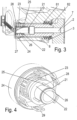
- figure 4 shows once again the wear sensor designed as a rotary sensor in a perspective view. It is easy to see here that the feeler element designed as the second sensor element 22 is fixed in a rotationally fixed manner by guide pins 25 fastened to the sensor housing according to the invention.
- the compression spring 23 presses the second sensor element 22 according to the figure 2 shown variant always against the contour 83 of the bearing beam 82 of the guide bearing 8.
- the conventional interfaces to the motor vehicle can be retained for evaluating the signals from the wear sensors.
- the measured value given by the wear sensors is preferably sent to a central circuit board and is preferably offset there with an additional total wear sensor, whereby this total wear sensor detects the total wear of both brake pads 5, 6 on the clamping side and on the back of the brake disc 4 and the wear of the brake disc.
- the measured values of the two wear sensors can be added up and transferred as a total value to an evaluation unit of the motor vehicle via an existing analog interface.
- the signals from the wear sensors are designed in such a way that they each output half the voltage value.
Landscapes
- Engineering & Computer Science (AREA)
- General Engineering & Computer Science (AREA)
- Mechanical Engineering (AREA)
- Braking Arrangements (AREA)
Description
- Die vorliegende Erfindung betrifft eine Schiebesattel Scheibenbremse eines Kraftfahrzeugs, insbesondere eines Nutzfahrzeugs gemäß dem Oberbegriff des Anspruchs 1, wie z.B. aus
DE A 10 2005 O22 597 DE 37 07 821 A1 undEP 0 978 665 B1 bekannt. Zur Erfassung des Verschleißes von Bremsbelägen, genauer des Reibbelags von Bremsbelägen, die an einer Belagträgerplatte des Bremsbelags befestigt sind, sind im Wesentlichen zwei Varianten aus dem Stand der Technik bekannt. - Bei einer ersten Variante wird über die Verschleißsensierung lediglich die Verschleißgrenze der Bremsbeläge erkannt. Dabei werden elektrische Kontakte, beispielsweise in Form von Drahtschleifen im Reibmaterial oder am Belagträger des Bremsbelags eingesetzt, die bei Erreichen der Verschleißgrenze mechanisch abgerieben werden und somit ein elektrisches Signal an einer Auswerteeinheit der Fahrzeugelektrik weiter geben. Nach dem Erreichen der Verschleißgrenze muss ein solcher Verschleißsensor ausgetauscht werden.
- Zur kontinuierlichen Verschleißerkennung von Reibbelägen müssten bei dieser Art von Verschleißsensierung mehrere solcher Leiterschleifen in den Reibbelag des Bremsbelags eingesetzt werden, was allerdings nur im begrenzten Umfang möglich ist.
- Die kontinuierliche Belagverschleißerkennung erfolgt gemäß einer weiteren Variante über die Position der Nachstellung des Schiebesattels und zwar als Summe des Belag- und Scheibenverschleißes. Dabei kann über einen möglicherweise ungleichmäßigen Verschleiß des zuspannseitigen Bremsbelags gegenüber dem rückseitigen Bremsbelag keine Aussage getroffen werden. Um hier ein unzulässiges Verschleißmaß der Bremsbeläge auszuschließen, muss ein solcher möglicher Ungleichverschleiß zwischen dem zuspannseitigen und dem rückseitigen Bremsbelag bei dem an die Auswerteeinheit abgegebenen Verschleißsignal berücksichtigt werden. Nachteilig an dieser Vorgehensweise ist, dass sich dadurch die maximal nutzbare Reibbelagmasse vermindert.
- Aufgabe der vorliegenden Erfindung ist es, eine Schiebesattel-Scheibenbremse eines Kraftfahrzeugs bereit zu stellen, welches zum einen eine kontinuierliche Verschleißsensierung ermöglicht und zum zweiten keine Erneuerung der Verschleißsensoren beim Belagwechsel erfordert.
- Diese Aufgabe wird durch eine Schiebesattel-Scheibenbremse eines Kraftfahrzeugs mit den Merkmalen des Anspruchs 1 gelöst.
- Vorteilhafte Ausführungsvarianten der Erfindung sind Gegenstand der Unteransprüche.
- Gemäß einer weiteren vorteilhaften Ausführungsvariante ist der Verschleißsensor als Drehsensor ausgebildet, wobei zwischen dem ersten Sensorbauteil und dem zweiten Sensorbauteil eine Welle mit auf der Mantelfläche angeordnetem Steilgewinde vorgesehen ist, die mit einem entsprechenden Steilgewinde an der Innenseite des ringförmig ausgebildeten zweiten Sensorbauteils im Eingriff steht, sodass eine Verschiebung des Bremssattels einer Rotation der Welle um einen Winkel α bewirkt, die eine Änderung des von dem Verschleißsensor an die Auswerteschaltung abgegebenen Signals hervorruft. Durch die Erfassung der Drehbewegung der Welle kann beispielsweise über ein Drehpotentiometer ein Signal ausgegeben werden, dass wiederum der Verschiebung des Bremssattels gegenüber dem feststehenden Lagerholm des Führungslagers bestimmt werden.
- In einer vorteilhaften Ausgestaltung weist die Scheibenbremse einen weiteren, die Summe aus Bremsbelag und Bremsscheibenverschleiß ermittelten Verschleißsensor auf, der mit der Auswerteschaltung verbunden ist, wobei die von den verschiedenen Verschleißsensoren ermittelten Verschleißsignale in der Auswerteschaltung aufaddiert oder verglichen werden. So kann beispielsweise durch Vergleich der beiden Signale, beispielsweise in Gestalt von Spannungssignalen, ein sogenanntes "Worst-Case"-Signal an die Auswerteeinheit des Kraftfahrzeugs übergeben werden, wobei das "Worst-Case"-Signal der größeren der beiden Spannungen der von den beiden Sensoren abgegebenen Spannungssignale entspricht.
- Nachfolgend werden Ausführungsbeispiele anhand der beiliegenden Zeichnungen näher erläutert.
- Es zeigen:
- Figuren 1a und 1b
- eine erste nicht-erfindungsgemäße Ausführungsvariante einer Scheibenbremse in teilweise geschnittener Darstellung mit unverschlissenen bzw. verschlissenen Bremsbelägen;
- Figur 2
- eine Detailansicht der in
Figur 1 gezeigten Ausführungsvariante der Scheibenbremse; - Figur 3
- eine alternative Ausführungsvariante eines in der Scheibenbremse eingesetzten Verschleißsensor in Gestalt eines Drehsensors und
- Figur 4
- eine perspektivische Darstellung des Verschleißsensors aus
Figur 3 . - In der nachfolgenden Figurenbeschreibung beziehen sich Begriffe wie oben, unten, links, rechts, vorne, hinten usw. ausschließlich auf die in den jeweiligen Figuren gewählte beispielhafte Darstellung und Position der Scheibenbremse, Bremssattel, Verschleißsensor und dergleichen. Diese Begriffe sind nicht einschränkend zu verstehen, das heißt, durch verschiedene Arbeitsstellungen oder die spiegelsymmetrische Auslegung oder dergleichen können sich diese Bezüge ändern.
- In der
Figur 1 ist in einer teilweise geschnittenen Frontansicht eine Schiebesattel-Scheibenbremse gezeigt, mit einer Bremsscheibe 4 und einem einen Teil der Bremsscheibe 4 umgreifenden ortsfesten Bremsträger 2. Auf der Zuspannseite (inFigur 1 links) der Bremsscheibe 4 ist ein die Bremsscheibe 4 und den Bremsträger 2 überspannender Bremssattel 3 auf einem Führungslager 8 verschiebbar gelagert, auf dem der Bremssattel 3 je nach Verschleißzustand der Reibbeläge 51, 61 von zuspannseitig und rückseitig der Bremsscheibe 4 angeordneten Bremsbelägen 5, 6 axial zur Drehachse der Bremsscheibe 4 verschiebbar. -
Figur 1a zeigt dabei die Position des verschiebbaren Bremssattels 3 bei eingesetzten unverschlissenen Bremsbelägen 5, 6.Figur 1b zeigt die Position des Bremssattels, um eine Distanz x verschoben, bei verschlissenen Bremsbelägen 5, 6. Gut zu erkennen ist hier, dass die Distanz x, um die der Bremssattel 3 verschoben wurde, dem Belag- und Bremsscheibenverschleiß auf der Rückseite der Bremsscheibe 4 entspricht. - Das Führungslager 8 besteht im Wesentlichen aus einem Lagerholm 82, der über eine Schraube 7 am Bremsträger festgeschraubt ist und einer den Lagerholm umgreifenden Lagerhülse 81, die bremsscheibenseitig beispielsweise mit einer Ringmanschette am Lagerholm 82 abgedichtet ist, die sich zusammen mit dem Bremssattel 3 beim Verschieben des Bremssattels 3 auf Grund eines Verschleißes der Bremsbeläge 5, 6 auf dem feststehenden Lagerholm 82 verschiebt.
- Der Schraubenkopf 71 der Schraube 7, mit dem der Lagerholm 82 am Bremsträger 2 angeschraubt ist, sitzt dabei tief in einer Bohrung des Lagerholms 82. In dieser Bohrung am von der Bremsscheibe 4 abgewandten Ende des Lagerholms 82 ist ein Verschleißsensor eingesetzt, mit im wesentlichen zwei Sensorbauteilen, wobei, wie in den
Figuren 2 und3 zu erkennen ist, ein erstes Sensorbauteil 10, 24 am Bremssattel 3 befestigt ist, das in Verbindung mit einem am Führungslager 8 anliegenden zweiten Sensorbauteil 12, 22 steht, wobei der Verschleißsensor selbst mit einer Auswerteschaltung verbunden ist, an die die Signale des Verschleißsensors und zur Berechnung der optimalen Bremssattelstellung weitergeben werden. - Das erste Sensorbauteil 10, 24 ist dabei, wie in den
Figuren 2 ,3 , welche unterschiedliche Ausführungsvarianten des Verschleißsensors zeigen, gezeigt, als Sensorgehäuse, ausgebildet, das bevorzugt in eine das Führungslager 8 aufnehmende Öffnung verschließende Lagerkappe integriert ist oder auch als die Öffnung des Führungslagers 8 verschließende Lagerkappe selbst ausgebildet ist. - Das zweite Sensorbauteil 12, 22 ist hier als federbelastet an das Führungslager 8 angedrücktes Tastelement ausgebildet, wobei die Federbelastung des zweiten Sensorbauteils vorzugsweise durch eine Druckfeder 13 erfolgt. Das Tastelement 12, 22 wird dabei bevorzugt an eine Kontur 83 des Lagerholms 82 des Führungslagers 8 angedrückt, wodurch bewirkt wird, dass das Tastelement wie auch der Führungsholm 82 stets in seiner Position verharrt und nicht mit dem Bremssattel 3 bzw. dem ersten Sensorbauteil 10, 26 mitbewegt wird. Dadurch kann die aus der Verschiebung des Bremssattels 3 resultierende Relativbewegung durch eine Relativbewegung des ersten Sensorbauteils, hier des Sensorgehäuses zu dem zweiten Sensorbauteil 12, 22, hier dem Tastelement, über ein Messsystem 11 erfasst werden, das hier beispielhaft in Gestalt eines Schleifers eines Potentiometer dargestellt ist.
- Bei der in
Figur 2 dargestellten Ausführungsvariante der Scheibenbremse ist der Verschleißsensor als Linear-Sensor ausgebildet, wobei der am Tastelement 12 befestigte Schleifer 11 einen Steg des Sensorgehäuses berührt, wobei aus der Berührposition die Verschiebung des Sensorgehäuses 10 gegenüber dem Tastelement 12 herleitbar ist. Wie oben erwähnt, entspricht die Verschiebung des Sensorgehäuses 10 gegenüber dem Tastelement 12 der Verschiebung des Bremssattels 3 und damit dem rückseitigen Bremsbelag- und Bremsscheibenverschleiß. - Bei der Ausführungsvariante der Scheibenbremse gemäß
Figur 3 ist an Stelle des Linear-Sensors ein Drehsensor in den Hohlraum des Lagerholms 82 vor der Schraube 7, bzw. dem Schraubenkopf 71 eingesetzt. - Auch bei diesem als Drehsensor ausgebildeten Verschleißsensor ist das erste Sensorbauteil 24 als Sensorgehäuse ausgebildet und das zweite Sensorbauteil 22 als Tastelement. An dem Sensorgehäuse 24 ist eine Welle 26 drehbar um eine Achse parallel zur Drehachse der Bremsscheibe angeordnet, die sich durch das bevorzugt als Ringscheibe ausgebildete Tastelement 22 hindurch erstreckt.
- Auf der Mantelfläche der Welle 26 ist ein Steilgewinde 28 vorgesehen, dass mit einem entsprechenden Steilgewinde an der Innenseite des ringförmig ausgebildeten zweiten Sensorbauteils 22 im Eingriff steht, so dass eine Verschiebung des Bremssattels 3 einer Rotation der Welle 26 um einen Winkel α berührt, die eine Änderung des von dem Verschleißsensor an die Auswertungsschaltung abgegebenen Signals hervorruft. Auch hier kann das signalerzeugende Messeinheit 27 als Potentiometer ausgebildet sein, wobei die Winkelposition der Welle 26 hier das der Position des Bremssattels entsprechende Signal bewirkt.
- Der Steigungswinkel des Steilgewindes der Welle 26 richtet sich dabei nach dem zu erwartenden Reibungskoeffizienten und darf dabei nicht im Bereich der Selbsthemmung liegen, so dass hier gelten muss, dass der Arctan des Reibungskoeffizienten sehr viel kleiner ist als der Steigungswinkel des Steilgewindes. Der Steigungswinkel entspricht dabei vorzugsweise weniger als eine Umdrehung der Welle über den gesamten Verschiebebereich des Bremssattels 3.
-
Figur 4 zeigt noch einmal den als Drehsensor ausgebildeten Verschleißsensor in einer perspektivischen Darstellung. Gut zu erkennen ist hier, dass das als zweites Sensorelement 22 ausgebildete Tastelement durch am Sensorgehäuse erfindungsgemäß befestigte Führungsstifte 25 drehfest festgelegt ist. Die Druckfeder 23 drückt das zweite Sensorelement 22 dabei entsprechend der inFigur 2 gezeigten Ausführungsvariante stets gegen die Kontur 83 des Lagerholms 82 des Führungslagers 8. - Zur Auswertung der Signale der Verschleißsensoren können die herkömmlichen Schnittstellen zum Kraftfahrzeug beibehalten werden. Der von den Verschleißsensoren gegebene Messwert wird dabei vorzugsweise auf eine zentrale Platine geleitet und dort vorzugsweise mit einem zusätzlich vorhandenen Summenverschleißsensor verrechnet, wobei dieser Summenverschleißsensor den Gesamtverschleiß beider Bremsbeläge 5, 6 zuspannseitig und rückseitig der Bremsscheibe 4 und den Verschleiß der Bremsscheibe erkennt. So können beispielsweise die Messwerte der beiden Verschleißsensoren aufaddiert und als Summenwert über eine vorhandene Analogschnittstelle an eine Auswerteeinheit des Kraftfahrzeugs übergeben werden. Dabei sind die Signale der Verschleißsensoren so beschaffen, dass sie jeweils den halben Spannungswert ausgeben.
- In einer alternative Auswerteschaltung, bei der beide Sensoren im gleichen Spannungsbereich arbeiten, werden die Signale der beiden Verschleißsensoren verglichen und der größere der beiden Spannungen an die Auswerteeinheit des Kraftfahrzeugs übergeben.
-
- 2
- Bremsträger
- 3
- Bremssattel
- 4
- Bremsscheibe
- 5
- Bremsbelag
- 6
- Bremsbelag
- 7
- Schraube
- 8
- Führungslager
- 10
- Sensorbauteil
- 11
- Schleifer
- 12
- Sensorbauteil
- 13
- Druckfeder
- 22
- Sensorbauteil
- 23
- Druckfeder
- 24
- Sensorbauteil
- 25
- Führungsstifte
- 26
- Welle
- 27
- Messeinheit
- 28
- Steilgewinde
- 51
- Reibbelag
- 52
- Belagträgerplatte
- 61
- Reibbelag
- 62
- Belagträgerplatte
- 71
- Schraubenkopf
- 82
- Lagerholm
- 83
- Kontur
Claims (4)
- Schiebesattel-Scheibenbremse eines Kraftfahrzeugs, insbesondere eines Nutzfahrzeugs, aufweisend- einen eine Bremsscheibe (4) übergreifenden und relativ zu einem ortsfesten Bremsträger (2) und axial zur Bremsscheibe (4) auf einem Führungslager (8) verschiebbar gelagerten Bremssattel (3),- mindestens zwei Bremsbeläge (5, 6) mit einer Belagträgerplatte (52, 62) und einem daran befestigten Reibbelag (51, 61), wobei jeweils mindestens ein Bremsbelag (6) zuspannseitig und mindestens ein Bremsbelag (5) rückseitig der Bremsscheibe (4) angeordnet ist,- eine Einrichtung zur Erfassung eines Bremsbelagverschleißes mit einem den Verschiebeweg (x) des Bremssattels erfassenden Verschleißsensor,- wobei ein als Sensorgehäuse ausgebildetes erstes Sensorbauteil (10, 24) am Bremssattel (3) befestigt ist, das in Verbindung mit einem an dem Führungslager (8) anliegenden zweiten Sensorbauteil (12, 22) steht,- wobei der Verschleißsensor mit einer Auswerteschaltung verbunden und in einer das Führungslager (8) aufnehmenden Öffnung des Bremssattel (3) angeordnet ist,- wobei das erste Sensorbauteil (10, 24) als eine das Führungslager (8) aufnehmende Öffnung verschließende Lagerkappe ausgebildet ist;wobei das zweite Sensorbauteil (12, 22) als federbelastet an das Führungstaqer(8) angedrücktes Tastelement ausgebildet ist;wobei das als Tastelement ausgebildete zweite Sensorbauteil (12, 22) an eine Kontur (83) eines Lagerholms (82) des Führungslagers (8) oder eine Kontur der Schraube (7) angedrückt ist;dadurch gekennzeichnet, dassdas als zweites Sensorelement (22) ausgebildete Tastelement durch am Sensorgehäuse befestigte Führungsstifte (25) drehfest festgelegt ist.
- Scheibenbremse nach Anspruch 1, dadurch gekennzeichnet, dass der Verschleißsensor als Linearsensor ausgebildet ist, wobei das erste Sensorbauteil (10) gegenüber dem zweiten Sensorbauteil (12) linear verschiebbar ist.
- Scheibenbremse nach Anspruch 1, dadurch gekennzeichnet, dass der Verschleißsensor als Drehsensor ausgebildet ist, wobei zwischen dem ersten Sensorbauteil (24) und dem zweiten Sensorbauteil (22) eine Welle (26) mit auf der Mantelfläche angeordnetem Steilgewinde (28) vorgesehen ist, die mit einem entsprechenden Steilgewinde an der Innenseite des ringförmig ausgebildeten zweiten Sensorbauteils (22) im Eingriff steht, so dass eine Verschiebung des Bremssattel (3) eine Rotation der Welle (26) um einen Winkel α bewirkt, die eine Änderung des von dem Verschleißsensor an die Auswerteschaltung abgegebenen Signals hervorruft.
- Scheibenbremse nach einem der vorstehenden Ansprüche, dadurch gekennzeichnet, dass die Scheibenbremse einen weiteren, die Summe aus Bremsbelag- und Bremsscheibenverschleiß ermittelnden Verschleißsensor aufweist, der mit der Auswerteschaltung verbunden ist, wobei die von den Verschleißsensoren ermittelten Verschleißsignale in der Auswerteschaltung aufaddiert oder verglichen werden.
Applications Claiming Priority (2)
| Application Number | Priority Date | Filing Date | Title |
|---|---|---|---|
| DE102012006105.6A DE102012006105B4 (de) | 2012-03-26 | 2012-03-26 | Schiebesattel- Scheibenbremse eines Kraftfahrzeugs |
| PCT/EP2013/056024 WO2013143992A1 (de) | 2012-03-26 | 2013-03-22 | Schiebesattel-scheibenbremse eines kraftfahrzeugs |
Publications (3)
| Publication Number | Publication Date |
|---|---|
| EP2831447A1 EP2831447A1 (de) | 2015-02-04 |
| EP2831447B1 EP2831447B1 (de) | 2017-11-01 |
| EP2831447B2 true EP2831447B2 (de) | 2023-03-15 |
Family
ID=47915239
Family Applications (1)
| Application Number | Title | Priority Date | Filing Date |
|---|---|---|---|
| EP13711391.6A Active EP2831447B2 (de) | 2012-03-26 | 2013-03-22 | Schiebesattel-scheibenbremse eines kraftfahrzeugs |
Country Status (4)
| Country | Link |
|---|---|
| EP (1) | EP2831447B2 (de) |
| DE (1) | DE102012006105B4 (de) |
| ES (1) | ES2657611T3 (de) |
| WO (1) | WO2013143992A1 (de) |
Families Citing this family (14)
| Publication number | Priority date | Publication date | Assignee | Title |
|---|---|---|---|---|
| DE102009008341A1 (de) * | 2009-02-11 | 2010-08-19 | Knorr-Bremse Systeme für Nutzfahrzeuge GmbH | Fahrzeugbremse |
| US10570974B2 (en) * | 2015-04-17 | 2020-02-25 | Goodrich Corporation | Brake position and wear detection systems and methods |
| DE102015117249B4 (de) * | 2015-10-09 | 2017-07-13 | Knorr-Bremse Systeme für Nutzfahrzeuge GmbH | Verschleisssensorvorrichtung für eine scheibenbremsenanordnung |
| DE102015013199A1 (de) * | 2015-10-12 | 2017-04-13 | Wabco Europe Bvba | Überwachungseinrichtung für eine Scheibenbremse eines Kraftfahrzeuges |
| DE102016011190A1 (de) | 2016-09-15 | 2018-03-15 | Wabco Europe Bvba | Verschleissüberwachungsvorrichtung und Scheibenbremse mit einer solchen Verschleissüberwachungsvorrichtung |
| US10233984B2 (en) | 2017-04-24 | 2019-03-19 | Ford Global Technologies, Llc | Multiple function brake caliper guide pin |
| US10800386B2 (en) | 2017-07-24 | 2020-10-13 | Goodrich Corporation | Brake position system |
| US10493962B2 (en) | 2017-07-24 | 2019-12-03 | Goodrich Corporation | Brake position system |
| EP3492768B1 (de) * | 2017-11-29 | 2021-02-24 | Meritor Heavy Vehicle Braking Systems (UK) Limited | Sattelführungsanordnung |
| DE102018116268A1 (de) | 2018-07-05 | 2020-01-09 | Knorr-Bremse Systeme für Nutzfahrzeuge GmbH | Scheibenbremse und Verfahren zum Zustandsüberwachen einer Scheibenbremse |
| EP3872360A1 (de) * | 2020-02-28 | 2021-09-01 | Meritor Heavy Vehicle Braking Systems (UK) Limited | Sattelführungsanordnung |
| CN113685468B (zh) * | 2021-09-07 | 2023-03-28 | 北京建筑大学 | 一种制动闸片剩余厚度的检测装置 |
| DE102023100789B3 (de) * | 2023-01-13 | 2024-06-13 | Zollern Gmbh & Co. Kg | Bremse mit einer Einrichtung zur Ermittlung einer Verschleißgrenze |
| DE102023107309A1 (de) * | 2023-03-23 | 2024-09-26 | Zf Cv Systems Europe Bv | Scheibenbremse mit Verschleißsensor |
Citations (1)
| Publication number | Priority date | Publication date | Assignee | Title |
|---|---|---|---|---|
| DE3707821A1 (de) † | 1987-03-11 | 1988-09-22 | Bayerische Motoren Werke Ag | Vorrichtung zur anzeige des bremsbelagverschleisses einer schwimmsattel-scheibenbremse |
Family Cites Families (7)
| Publication number | Priority date | Publication date | Assignee | Title |
|---|---|---|---|---|
| DE3903306A1 (de) * | 1989-02-04 | 1990-08-09 | Teves Gmbh Alfred | Reibbelag-warneinrichtung |
| DE4213581C1 (en) | 1992-04-24 | 1993-05-27 | Deutsche Perrot-Bremse Gmbh, 6800 Mannheim, De | Wear indicator for slide saddle disc brake - has sensors for movement of brake saddle w.r.t. local reference point and w.r.t. actuating mechanism and displays difference value |
| DE69824408T2 (de) * | 1998-08-05 | 2005-06-23 | Freni Brembo S.P.A. | Vorrichtung zum Anzeigen des Belagverschleisses von Schwimmsattel-Scheibenbremsen |
| EP0978665B1 (de) | 1998-08-05 | 2004-06-09 | Freni Brembo S.p.A. | Vorrichtung zum Anzeigen des Belagverschleisses von Schwimmsattel-Scheibenbremsen |
| DE102005022597A1 (de) | 2005-05-17 | 2006-11-30 | Continental Teves Ag & Co. Ohg | Schwimmsattel-Scheibenbremse mit Vorrichtung zur Bremsbelagverschleißbestimmung |
| DE102005053303B4 (de) | 2005-11-09 | 2021-04-08 | Bpw Bergische Achsen Kg | Vorrichtung zur Anzeige des Verschleißzustandes von Fahrzeugbremsen |
| JP2009243564A (ja) * | 2008-03-31 | 2009-10-22 | Nisshinbo Holdings Inc | ピンスライド形ディスクブレーキ装置 |
-
2012
- 2012-03-26 DE DE102012006105.6A patent/DE102012006105B4/de not_active Expired - Fee Related
-
2013
- 2013-03-22 EP EP13711391.6A patent/EP2831447B2/de active Active
- 2013-03-22 ES ES13711391.6T patent/ES2657611T3/es active Active
- 2013-03-22 WO PCT/EP2013/056024 patent/WO2013143992A1/de not_active Ceased
Patent Citations (1)
| Publication number | Priority date | Publication date | Assignee | Title |
|---|---|---|---|---|
| DE3707821A1 (de) † | 1987-03-11 | 1988-09-22 | Bayerische Motoren Werke Ag | Vorrichtung zur anzeige des bremsbelagverschleisses einer schwimmsattel-scheibenbremse |
Also Published As
| Publication number | Publication date |
|---|---|
| WO2013143992A1 (de) | 2013-10-03 |
| EP2831447B1 (de) | 2017-11-01 |
| DE102012006105B4 (de) | 2024-06-13 |
| ES2657611T3 (es) | 2018-03-06 |
| EP2831447A1 (de) | 2015-02-04 |
| DE102012006105A1 (de) | 2013-09-26 |
Similar Documents
| Publication | Publication Date | Title |
|---|---|---|
| EP2831447B2 (de) | Schiebesattel-scheibenbremse eines kraftfahrzeugs | |
| EP2547927B1 (de) | Sensoreinheit für eine scheibenbremse | |
| EP0566006B1 (de) | Belagverschleissdetektor für eine druckluftbetätigte Scheibenbremse | |
| EP3362699B1 (de) | Überwachungseinrichtung für eine scheibenbremse eines kraftfahrzeuges | |
| DE19600819A1 (de) | Verschleißüberwachungsvorrichtung | |
| DE102013112813A1 (de) | Sensoreinrichtung und Scheibenbremse mit einer Sensoreinrichtung | |
| WO2016096070A1 (de) | Elektromagnetisch betätigbare bremsvorrichtung | |
| EP3529564B1 (de) | Sensoreinrichtung zur messung einer linear- oder rotationsbewegung eines messobjekts | |
| EP3784921B1 (de) | Verfahren zur anzeige eines anstehenden bremsbelagswechsels einer fahrzeugbremse | |
| EP2999897B1 (de) | Bremsvorrichtung | |
| DE4243875C2 (de) | Vorrichtung zur Erfassung des Belagverschleißes bei einer Scheibenbremse | |
| DE69705079T2 (de) | Mittel zur Erfassung des Zustandes einer Bremse | |
| EP0659243B2 (de) | Belagverschleissdetektor für eine scheibenbremse | |
| EP2867557B1 (de) | Scheibenbremse eines kraftfahrzeugs | |
| DE19738317B4 (de) | Vorrichtung zur kontinuierlichen Bestimmung des Verschleißzustandes von Reibbelägen | |
| EP0567155B1 (de) | Verschleissüberwachungsvorrichtung für eine Gleitsattel-Scheibenbremse | |
| DE102012006088B4 (de) | Schiebesattel-Scheibenbremse eines Kraftfahrzeugs | |
| DE10390447T5 (de) | Digitaler Sensor | |
| DE10201901C5 (de) | Scheibenbremse, insbesondere für ein Nutzfahrzeug, mit Belagverschleißanzeige | |
| WO2020057911A1 (de) | Nachrüstbares messsystem zur ermittlung eines verschleisses eines bremsbelags einer reibungsbremse | |
| DE102008003924B4 (de) | Pneumatisch oder elektromotorisch betätigbare Scheibenbremse | |
| DE102005053303B4 (de) | Vorrichtung zur Anzeige des Verschleißzustandes von Fahrzeugbremsen | |
| DE69310664T2 (de) | Verschleisszustand-Erfassungsvorrichtung für Reibbremsbeläge | |
| WO2024160667A1 (de) | Scheibenbremse für ein nutzfahrzeug mit einer verschleisssensorik | |
| EP3601833B1 (de) | Scheibenbremse für ein nutzfahrzeug |
Legal Events
| Date | Code | Title | Description |
|---|---|---|---|
| PUAI | Public reference made under article 153(3) epc to a published international application that has entered the european phase |
Free format text: ORIGINAL CODE: 0009012 |
|
| 17P | Request for examination filed |
Effective date: 20141027 |
|
| AK | Designated contracting states |
Kind code of ref document: A1 Designated state(s): AL AT BE BG CH CY CZ DE DK EE ES FI FR GB GR HR HU IE IS IT LI LT LU LV MC MK MT NL NO PL PT RO RS SE SI SK SM TR |
|
| AX | Request for extension of the european patent |
Extension state: BA ME |
|
| DAX | Request for extension of the european patent (deleted) | ||
| GRAP | Despatch of communication of intention to grant a patent |
Free format text: ORIGINAL CODE: EPIDOSNIGR1 |
|
| STAA | Information on the status of an ep patent application or granted ep patent |
Free format text: STATUS: GRANT OF PATENT IS INTENDED |
|
| INTG | Intention to grant announced |
Effective date: 20170529 |
|
| GRAS | Grant fee paid |
Free format text: ORIGINAL CODE: EPIDOSNIGR3 |
|
| GRAA | (expected) grant |
Free format text: ORIGINAL CODE: 0009210 |
|
| STAA | Information on the status of an ep patent application or granted ep patent |
Free format text: STATUS: THE PATENT HAS BEEN GRANTED |
|
| AK | Designated contracting states |
Kind code of ref document: B1 Designated state(s): AL AT BE BG CH CY CZ DE DK EE ES FI FR GB GR HR HU IE IS IT LI LT LU LV MC MK MT NL NO PL PT RO RS SE SI SK SM TR |
|
| REG | Reference to a national code |
Ref country code: GB Ref legal event code: FG4D Free format text: NOT ENGLISH |
|
| REG | Reference to a national code |
Ref country code: CH Ref legal event code: EP Ref country code: AT Ref legal event code: REF Ref document number: 942346 Country of ref document: AT Kind code of ref document: T Effective date: 20171115 |
|
| REG | Reference to a national code |
Ref country code: IE Ref legal event code: FG4D Free format text: LANGUAGE OF EP DOCUMENT: GERMAN |
|
| REG | Reference to a national code |
Ref country code: DE Ref legal event code: R096 Ref document number: 502013008710 Country of ref document: DE |
|
| REG | Reference to a national code |
Ref country code: SE Ref legal event code: TRGR |
|
| REG | Reference to a national code |
Ref country code: ES Ref legal event code: FG2A Ref document number: 2657611 Country of ref document: ES Kind code of ref document: T3 Effective date: 20180306 |
|
| REG | Reference to a national code |
Ref country code: NL Ref legal event code: MP Effective date: 20171101 |
|
| REG | Reference to a national code |
Ref country code: LT Ref legal event code: MG4D Ref country code: FR Ref legal event code: PLFP Year of fee payment: 6 |
|
| PG25 | Lapsed in a contracting state [announced via postgrant information from national office to epo] |
Ref country code: FI Free format text: LAPSE BECAUSE OF FAILURE TO SUBMIT A TRANSLATION OF THE DESCRIPTION OR TO PAY THE FEE WITHIN THE PRESCRIBED TIME-LIMIT Effective date: 20171101 Ref country code: NL Free format text: LAPSE BECAUSE OF FAILURE TO SUBMIT A TRANSLATION OF THE DESCRIPTION OR TO PAY THE FEE WITHIN THE PRESCRIBED TIME-LIMIT Effective date: 20171101 Ref country code: LT Free format text: LAPSE BECAUSE OF FAILURE TO SUBMIT A TRANSLATION OF THE DESCRIPTION OR TO PAY THE FEE WITHIN THE PRESCRIBED TIME-LIMIT Effective date: 20171101 Ref country code: NO Free format text: LAPSE BECAUSE OF FAILURE TO SUBMIT A TRANSLATION OF THE DESCRIPTION OR TO PAY THE FEE WITHIN THE PRESCRIBED TIME-LIMIT Effective date: 20180201 |
|
| PG25 | Lapsed in a contracting state [announced via postgrant information from national office to epo] |
Ref country code: BG Free format text: LAPSE BECAUSE OF FAILURE TO SUBMIT A TRANSLATION OF THE DESCRIPTION OR TO PAY THE FEE WITHIN THE PRESCRIBED TIME-LIMIT Effective date: 20180201 Ref country code: IS Free format text: LAPSE BECAUSE OF FAILURE TO SUBMIT A TRANSLATION OF THE DESCRIPTION OR TO PAY THE FEE WITHIN THE PRESCRIBED TIME-LIMIT Effective date: 20180301 Ref country code: RS Free format text: LAPSE BECAUSE OF FAILURE TO SUBMIT A TRANSLATION OF THE DESCRIPTION OR TO PAY THE FEE WITHIN THE PRESCRIBED TIME-LIMIT Effective date: 20171101 Ref country code: LV Free format text: LAPSE BECAUSE OF FAILURE TO SUBMIT A TRANSLATION OF THE DESCRIPTION OR TO PAY THE FEE WITHIN THE PRESCRIBED TIME-LIMIT Effective date: 20171101 Ref country code: GR Free format text: LAPSE BECAUSE OF FAILURE TO SUBMIT A TRANSLATION OF THE DESCRIPTION OR TO PAY THE FEE WITHIN THE PRESCRIBED TIME-LIMIT Effective date: 20180202 Ref country code: HR Free format text: LAPSE BECAUSE OF FAILURE TO SUBMIT A TRANSLATION OF THE DESCRIPTION OR TO PAY THE FEE WITHIN THE PRESCRIBED TIME-LIMIT Effective date: 20171101 |
|
| REG | Reference to a national code |
Ref country code: DE Ref legal event code: R026 Ref document number: 502013008710 Country of ref document: DE |
|
| PLBI | Opposition filed |
Free format text: ORIGINAL CODE: 0009260 |
|
| PG25 | Lapsed in a contracting state [announced via postgrant information from national office to epo] |
Ref country code: DK Free format text: LAPSE BECAUSE OF FAILURE TO SUBMIT A TRANSLATION OF THE DESCRIPTION OR TO PAY THE FEE WITHIN THE PRESCRIBED TIME-LIMIT Effective date: 20171101 Ref country code: EE Free format text: LAPSE BECAUSE OF FAILURE TO SUBMIT A TRANSLATION OF THE DESCRIPTION OR TO PAY THE FEE WITHIN THE PRESCRIBED TIME-LIMIT Effective date: 20171101 Ref country code: CY Free format text: LAPSE BECAUSE OF FAILURE TO SUBMIT A TRANSLATION OF THE DESCRIPTION OR TO PAY THE FEE WITHIN THE PRESCRIBED TIME-LIMIT Effective date: 20171101 Ref country code: SK Free format text: LAPSE BECAUSE OF FAILURE TO SUBMIT A TRANSLATION OF THE DESCRIPTION OR TO PAY THE FEE WITHIN THE PRESCRIBED TIME-LIMIT Effective date: 20171101 Ref country code: CZ Free format text: LAPSE BECAUSE OF FAILURE TO SUBMIT A TRANSLATION OF THE DESCRIPTION OR TO PAY THE FEE WITHIN THE PRESCRIBED TIME-LIMIT Effective date: 20171101 |
|
| PLAX | Notice of opposition and request to file observation + time limit sent |
Free format text: ORIGINAL CODE: EPIDOSNOBS2 |
|
| 26 | Opposition filed |
Opponent name: BPW BERGISCHE ACHSEN KG Effective date: 20180719 |
|
| PG25 | Lapsed in a contracting state [announced via postgrant information from national office to epo] |
Ref country code: SM Free format text: LAPSE BECAUSE OF FAILURE TO SUBMIT A TRANSLATION OF THE DESCRIPTION OR TO PAY THE FEE WITHIN THE PRESCRIBED TIME-LIMIT Effective date: 20171101 Ref country code: RO Free format text: LAPSE BECAUSE OF FAILURE TO SUBMIT A TRANSLATION OF THE DESCRIPTION OR TO PAY THE FEE WITHIN THE PRESCRIBED TIME-LIMIT Effective date: 20171101 Ref country code: PL Free format text: LAPSE BECAUSE OF FAILURE TO SUBMIT A TRANSLATION OF THE DESCRIPTION OR TO PAY THE FEE WITHIN THE PRESCRIBED TIME-LIMIT Effective date: 20171101 |
|
| PG25 | Lapsed in a contracting state [announced via postgrant information from national office to epo] |
Ref country code: MT Free format text: LAPSE BECAUSE OF FAILURE TO SUBMIT A TRANSLATION OF THE DESCRIPTION OR TO PAY THE FEE WITHIN THE PRESCRIBED TIME-LIMIT Effective date: 20171101 |
|
| REG | Reference to a national code |
Ref country code: CH Ref legal event code: PL |
|
| PG25 | Lapsed in a contracting state [announced via postgrant information from national office to epo] |
Ref country code: MC Free format text: LAPSE BECAUSE OF FAILURE TO SUBMIT A TRANSLATION OF THE DESCRIPTION OR TO PAY THE FEE WITHIN THE PRESCRIBED TIME-LIMIT Effective date: 20171101 Ref country code: SI Free format text: LAPSE BECAUSE OF FAILURE TO SUBMIT A TRANSLATION OF THE DESCRIPTION OR TO PAY THE FEE WITHIN THE PRESCRIBED TIME-LIMIT Effective date: 20171101 |
|
| REG | Reference to a national code |
Ref country code: BE Ref legal event code: MM Effective date: 20180331 |
|
| PLBB | Reply of patent proprietor to notice(s) of opposition received |
Free format text: ORIGINAL CODE: EPIDOSNOBS3 |
|
| REG | Reference to a national code |
Ref country code: IE Ref legal event code: MM4A |
|
| PG25 | Lapsed in a contracting state [announced via postgrant information from national office to epo] |
Ref country code: LU Free format text: LAPSE BECAUSE OF NON-PAYMENT OF DUE FEES Effective date: 20180322 |
|
| PG25 | Lapsed in a contracting state [announced via postgrant information from national office to epo] |
Ref country code: IE Free format text: LAPSE BECAUSE OF NON-PAYMENT OF DUE FEES Effective date: 20180322 |
|
| PG25 | Lapsed in a contracting state [announced via postgrant information from national office to epo] |
Ref country code: CH Free format text: LAPSE BECAUSE OF NON-PAYMENT OF DUE FEES Effective date: 20180331 Ref country code: LI Free format text: LAPSE BECAUSE OF NON-PAYMENT OF DUE FEES Effective date: 20180331 Ref country code: BE Free format text: LAPSE BECAUSE OF NON-PAYMENT OF DUE FEES Effective date: 20180331 |
|
| REG | Reference to a national code |
Ref country code: AT Ref legal event code: MM01 Ref document number: 942346 Country of ref document: AT Kind code of ref document: T Effective date: 20180322 |
|
| PG25 | Lapsed in a contracting state [announced via postgrant information from national office to epo] |
Ref country code: AT Free format text: LAPSE BECAUSE OF NON-PAYMENT OF DUE FEES Effective date: 20180322 |
|
| PGFP | Annual fee paid to national office [announced via postgrant information from national office to epo] |
Ref country code: IT Payment date: 20200325 Year of fee payment: 8 |
|
| PG25 | Lapsed in a contracting state [announced via postgrant information from national office to epo] |
Ref country code: PT Free format text: LAPSE BECAUSE OF FAILURE TO SUBMIT A TRANSLATION OF THE DESCRIPTION OR TO PAY THE FEE WITHIN THE PRESCRIBED TIME-LIMIT Effective date: 20171101 |
|
| APBM | Appeal reference recorded |
Free format text: ORIGINAL CODE: EPIDOSNREFNO |
|
| APBP | Date of receipt of notice of appeal recorded |
Free format text: ORIGINAL CODE: EPIDOSNNOA2O |
|
| APAH | Appeal reference modified |
Free format text: ORIGINAL CODE: EPIDOSCREFNO |
|
| PG25 | Lapsed in a contracting state [announced via postgrant information from national office to epo] |
Ref country code: HU Free format text: LAPSE BECAUSE OF FAILURE TO SUBMIT A TRANSLATION OF THE DESCRIPTION OR TO PAY THE FEE WITHIN THE PRESCRIBED TIME-LIMIT; INVALID AB INITIO Effective date: 20130322 Ref country code: MK Free format text: LAPSE BECAUSE OF NON-PAYMENT OF DUE FEES Effective date: 20171101 |
|
| PGFP | Annual fee paid to national office [announced via postgrant information from national office to epo] |
Ref country code: TR Payment date: 20200319 Year of fee payment: 8 Ref country code: FR Payment date: 20200325 Year of fee payment: 8 |
|
| PG25 | Lapsed in a contracting state [announced via postgrant information from national office to epo] |
Ref country code: AL Free format text: LAPSE BECAUSE OF FAILURE TO SUBMIT A TRANSLATION OF THE DESCRIPTION OR TO PAY THE FEE WITHIN THE PRESCRIBED TIME-LIMIT Effective date: 20171101 |
|
| PGFP | Annual fee paid to national office [announced via postgrant information from national office to epo] |
Ref country code: ES Payment date: 20200421 Year of fee payment: 8 |
|
| APBQ | Date of receipt of statement of grounds of appeal recorded |
Free format text: ORIGINAL CODE: EPIDOSNNOA3O |
|
| PG25 | Lapsed in a contracting state [announced via postgrant information from national office to epo] |
Ref country code: FR Free format text: LAPSE BECAUSE OF NON-PAYMENT OF DUE FEES Effective date: 20210331 |
|
| PLAB | Opposition data, opponent's data or that of the opponent's representative modified |
Free format text: ORIGINAL CODE: 0009299OPPO |
|
| R26 | Opposition filed (corrected) |
Opponent name: BPW BERGISCHE ACHSEN KG Effective date: 20180719 |
|
| PG25 | Lapsed in a contracting state [announced via postgrant information from national office to epo] |
Ref country code: IT Free format text: LAPSE BECAUSE OF NON-PAYMENT OF DUE FEES Effective date: 20210322 |
|
| REG | Reference to a national code |
Ref country code: ES Ref legal event code: FD2A Effective date: 20220630 |
|
| PLAB | Opposition data, opponent's data or that of the opponent's representative modified |
Free format text: ORIGINAL CODE: 0009299OPPO |
|
| PG25 | Lapsed in a contracting state [announced via postgrant information from national office to epo] |
Ref country code: ES Free format text: LAPSE BECAUSE OF NON-PAYMENT OF DUE FEES Effective date: 20210323 |
|
| R26 | Opposition filed (corrected) |
Opponent name: BPW BERGISCHE ACHSEN KG Effective date: 20180719 |
|
| APBU | Appeal procedure closed |
Free format text: ORIGINAL CODE: EPIDOSNNOA9O |
|
| PUAH | Patent maintained in amended form |
Free format text: ORIGINAL CODE: 0009272 |
|
| STAA | Information on the status of an ep patent application or granted ep patent |
Free format text: STATUS: PATENT MAINTAINED AS AMENDED |
|
| 27A | Patent maintained in amended form |
Effective date: 20230315 |
|
| AK | Designated contracting states |
Kind code of ref document: B2 Designated state(s): AL AT BE BG CH CY CZ DE DK EE ES FI FR GB GR HR HU IE IS IT LI LT LU LV MC MK MT NL NO PL PT RO RS SE SI SK SM TR |
|
| REG | Reference to a national code |
Ref country code: DE Ref legal event code: R102 Ref document number: 502013008710 Country of ref document: DE |
|
| REG | Reference to a national code |
Ref country code: SE Ref legal event code: RPEO |
|
| P01 | Opt-out of the competence of the unified patent court (upc) registered |
Effective date: 20230607 |
|
| PGFP | Annual fee paid to national office [announced via postgrant information from national office to epo] |
Ref country code: DE Payment date: 20240328 Year of fee payment: 12 |
|
| PGFP | Annual fee paid to national office [announced via postgrant information from national office to epo] |
Ref country code: SE Payment date: 20240326 Year of fee payment: 12 |
|
| PG25 | Lapsed in a contracting state [announced via postgrant information from national office to epo] |
Ref country code: TR Free format text: LAPSE BECAUSE OF NON-PAYMENT OF DUE FEES Effective date: 20210322 |
|
| REG | Reference to a national code |
Ref country code: DE Ref legal event code: R119 Ref document number: 502013008710 Country of ref document: DE |
|
| REG | Reference to a national code |
Ref country code: SE Ref legal event code: EUG |
|
| PG25 | Lapsed in a contracting state [announced via postgrant information from national office to epo] |
Ref country code: DE Free format text: LAPSE BECAUSE OF NON-PAYMENT OF DUE FEES Effective date: 20251001 |
|
| PG25 | Lapsed in a contracting state [announced via postgrant information from national office to epo] |
Ref country code: SE Free format text: LAPSE BECAUSE OF NON-PAYMENT OF DUE FEES Effective date: 20250323 |
|
| PGFP | Annual fee paid to national office [announced via postgrant information from national office to epo] |
Ref country code: GB Payment date: 20260319 Year of fee payment: 14 |