EP0978665B1 - Device for indicating lining wear in floating caliper disc brakes - Google Patents
Device for indicating lining wear in floating caliper disc brakes Download PDFInfo
- Publication number
- EP0978665B1 EP0978665B1 EP98830482A EP98830482A EP0978665B1 EP 0978665 B1 EP0978665 B1 EP 0978665B1 EP 98830482 A EP98830482 A EP 98830482A EP 98830482 A EP98830482 A EP 98830482A EP 0978665 B1 EP0978665 B1 EP 0978665B1
- Authority
- EP
- European Patent Office
- Prior art keywords
- caliper body
- caliper
- pads
- guide pin
- pad
- Prior art date
- Legal status (The legal status is an assumption and is not a legal conclusion. Google has not performed a legal analysis and makes no representation as to the accuracy of the status listed.)
- Expired - Lifetime
Links
Images


Classifications
-
- F—MECHANICAL ENGINEERING; LIGHTING; HEATING; WEAPONS; BLASTING
- F16—ENGINEERING ELEMENTS AND UNITS; GENERAL MEASURES FOR PRODUCING AND MAINTAINING EFFECTIVE FUNCTIONING OF MACHINES OR INSTALLATIONS; THERMAL INSULATION IN GENERAL
- F16D—COUPLINGS FOR TRANSMITTING ROTATION; CLUTCHES; BRAKES
- F16D66/00—Arrangements for monitoring working conditions, e.g. wear, temperature
- F16D66/02—Apparatus for indicating wear
- F16D66/021—Apparatus for indicating wear using electrical detection or indication means
- F16D66/026—Apparatus for indicating wear using electrical detection or indication means indicating different degrees of lining wear
-
- F—MECHANICAL ENGINEERING; LIGHTING; HEATING; WEAPONS; BLASTING
- F16—ENGINEERING ELEMENTS AND UNITS; GENERAL MEASURES FOR PRODUCING AND MAINTAINING EFFECTIVE FUNCTIONING OF MACHINES OR INSTALLATIONS; THERMAL INSULATION IN GENERAL
- F16D—COUPLINGS FOR TRANSMITTING ROTATION; CLUTCHES; BRAKES
- F16D55/00—Brakes with substantially-radial braking surfaces pressed together in axial direction, e.g. disc brakes
- F16D55/02—Brakes with substantially-radial braking surfaces pressed together in axial direction, e.g. disc brakes with axially-movable discs or pads pressed against axially-located rotating members
- F16D55/22—Brakes with substantially-radial braking surfaces pressed together in axial direction, e.g. disc brakes with axially-movable discs or pads pressed against axially-located rotating members by clamping an axially-located rotating disc between movable braking members, e.g. movable brake discs or brake pads
- F16D55/224—Brakes with substantially-radial braking surfaces pressed together in axial direction, e.g. disc brakes with axially-movable discs or pads pressed against axially-located rotating members by clamping an axially-located rotating disc between movable braking members, e.g. movable brake discs or brake pads with a common actuating member for the braking members
- F16D55/225—Brakes with substantially-radial braking surfaces pressed together in axial direction, e.g. disc brakes with axially-movable discs or pads pressed against axially-located rotating members by clamping an axially-located rotating disc between movable braking members, e.g. movable brake discs or brake pads with a common actuating member for the braking members the braking members being brake pads
- F16D55/226—Brakes with substantially-radial braking surfaces pressed together in axial direction, e.g. disc brakes with axially-movable discs or pads pressed against axially-located rotating members by clamping an axially-located rotating disc between movable braking members, e.g. movable brake discs or brake pads with a common actuating member for the braking members the braking members being brake pads in which the common actuating member is moved axially, e.g. floating caliper disc brakes
- F16D55/2265—Brakes with substantially-radial braking surfaces pressed together in axial direction, e.g. disc brakes with axially-movable discs or pads pressed against axially-located rotating members by clamping an axially-located rotating disc between movable braking members, e.g. movable brake discs or brake pads with a common actuating member for the braking members the braking members being brake pads in which the common actuating member is moved axially, e.g. floating caliper disc brakes the axial movement being guided by one or more pins engaging bores in the brake support or the brake housing
- F16D55/22655—Constructional details of guide pins
-
- F—MECHANICAL ENGINEERING; LIGHTING; HEATING; WEAPONS; BLASTING
- F16—ENGINEERING ELEMENTS AND UNITS; GENERAL MEASURES FOR PRODUCING AND MAINTAINING EFFECTIVE FUNCTIONING OF MACHINES OR INSTALLATIONS; THERMAL INSULATION IN GENERAL
- F16D—COUPLINGS FOR TRANSMITTING ROTATION; CLUTCHES; BRAKES
- F16D55/00—Brakes with substantially-radial braking surfaces pressed together in axial direction, e.g. disc brakes
- F16D55/02—Brakes with substantially-radial braking surfaces pressed together in axial direction, e.g. disc brakes with axially-movable discs or pads pressed against axially-located rotating members
- F16D55/22—Brakes with substantially-radial braking surfaces pressed together in axial direction, e.g. disc brakes with axially-movable discs or pads pressed against axially-located rotating members by clamping an axially-located rotating disc between movable braking members, e.g. movable brake discs or brake pads
- F16D55/224—Brakes with substantially-radial braking surfaces pressed together in axial direction, e.g. disc brakes with axially-movable discs or pads pressed against axially-located rotating members by clamping an axially-located rotating disc between movable braking members, e.g. movable brake discs or brake pads with a common actuating member for the braking members
- F16D55/225—Brakes with substantially-radial braking surfaces pressed together in axial direction, e.g. disc brakes with axially-movable discs or pads pressed against axially-located rotating members by clamping an axially-located rotating disc between movable braking members, e.g. movable brake discs or brake pads with a common actuating member for the braking members the braking members being brake pads
- F16D55/226—Brakes with substantially-radial braking surfaces pressed together in axial direction, e.g. disc brakes with axially-movable discs or pads pressed against axially-located rotating members by clamping an axially-located rotating disc between movable braking members, e.g. movable brake discs or brake pads with a common actuating member for the braking members the braking members being brake pads in which the common actuating member is moved axially, e.g. floating caliper disc brakes
- F16D55/2265—Brakes with substantially-radial braking surfaces pressed together in axial direction, e.g. disc brakes with axially-movable discs or pads pressed against axially-located rotating members by clamping an axially-located rotating disc between movable braking members, e.g. movable brake discs or brake pads with a common actuating member for the braking members the braking members being brake pads in which the common actuating member is moved axially, e.g. floating caliper disc brakes the axial movement being guided by one or more pins engaging bores in the brake support or the brake housing
- F16D55/227—Brakes with substantially-radial braking surfaces pressed together in axial direction, e.g. disc brakes with axially-movable discs or pads pressed against axially-located rotating members by clamping an axially-located rotating disc between movable braking members, e.g. movable brake discs or brake pads with a common actuating member for the braking members the braking members being brake pads in which the common actuating member is moved axially, e.g. floating caliper disc brakes the axial movement being guided by one or more pins engaging bores in the brake support or the brake housing by two or more pins
-
- F—MECHANICAL ENGINEERING; LIGHTING; HEATING; WEAPONS; BLASTING
- F16—ENGINEERING ELEMENTS AND UNITS; GENERAL MEASURES FOR PRODUCING AND MAINTAINING EFFECTIVE FUNCTIONING OF MACHINES OR INSTALLATIONS; THERMAL INSULATION IN GENERAL
- F16D—COUPLINGS FOR TRANSMITTING ROTATION; CLUTCHES; BRAKES
- F16D66/00—Arrangements for monitoring working conditions, e.g. wear, temperature
- F16D66/02—Apparatus for indicating wear
- F16D66/021—Apparatus for indicating wear using electrical detection or indication means
- F16D66/022—Apparatus for indicating wear using electrical detection or indication means indicating that a lining is worn to minimum allowable thickness
- F16D66/025—Apparatus for indicating wear using electrical detection or indication means indicating that a lining is worn to minimum allowable thickness sensing the position of parts of the brake system other than the braking members, e.g. limit switches mounted on primary cylinders
-
- F—MECHANICAL ENGINEERING; LIGHTING; HEATING; WEAPONS; BLASTING
- F16—ENGINEERING ELEMENTS AND UNITS; GENERAL MEASURES FOR PRODUCING AND MAINTAINING EFFECTIVE FUNCTIONING OF MACHINES OR INSTALLATIONS; THERMAL INSULATION IN GENERAL
- F16D—COUPLINGS FOR TRANSMITTING ROTATION; CLUTCHES; BRAKES
- F16D55/00—Brakes with substantially-radial braking surfaces pressed together in axial direction, e.g. disc brakes
- F16D2055/0004—Parts or details of disc brakes
- F16D2055/0008—Brake supports
-
- F—MECHANICAL ENGINEERING; LIGHTING; HEATING; WEAPONS; BLASTING
- F16—ENGINEERING ELEMENTS AND UNITS; GENERAL MEASURES FOR PRODUCING AND MAINTAINING EFFECTIVE FUNCTIONING OF MACHINES OR INSTALLATIONS; THERMAL INSULATION IN GENERAL
- F16D—COUPLINGS FOR TRANSMITTING ROTATION; CLUTCHES; BRAKES
- F16D55/00—Brakes with substantially-radial braking surfaces pressed together in axial direction, e.g. disc brakes
- F16D2055/0004—Parts or details of disc brakes
- F16D2055/0016—Brake calipers
Definitions
- the present invention relates to a device for indicating wear of the pads of friction material in so-called floating calipers according to the preamble of claim 5 , and to a floating caliper comprising said device, according to the preamble of claim 1.
- the pads of friction material in the brakes are subject to wear and have to be replaced when their thickness falls below a minimum value in order to ensure safe braking.
- US 5,087,907 describes a friction lining warning device with a plurality of warning points indicating different thicknesses of the friction lining.
- the device comprises a switch housing which is externally stationarily positioned at the caliper housing and which houses a stud, which is stationarily positioned at a pin on which the caliper housing is guided.
- the switch housing defines internally a surface at which switches are positioned which release when the stud moves. The switches release when the stud has travelled a predetermined distance set by the distance of the single switches from a reference point inside the switch housing.
- warning devices have the disadvantage that they take up a lot of room around the brake caliper, where the space available is limited, and that they do not allow the pads to be replaced without first having to be removed.
- the object of the present invention is therefore to provide a warning device that allows the change in thickness of at least one of the pads of a brake caliper to be monitored continuously, thereby giving the driver of the vehicle on which the brake is fitted a signal that lets him know the actual state of wear of the pad and that also enables the remaining mileage permitted by the pad to be calculated and thus displayed instantaneously.
- a further object of the present invention is to devise a warning device which is compact and which allows the pads to be replaced without first having to remove it.
- the numeral 1 denotes the brake bracket as a whole which, in its known version, consists of two yokes 2 and 3, each shaped like an upturned U and lying in its own plane set a certain distance apart from each other.
- Each yoke has a crosspiece 2a and 3a and legs 2b, 2c and 3b, 3c, respectively.
- the yokes 2 and 3 are connected together by rod-like members 4 and 5 which are made in one piece with the pairs of legs 2b, 3b and 2c, 3c.
- the legs 2c and 3c each have a hole 6 and 7 respectively which, via screw means (not illustrated), enable the bracket to be fixed to the wheel stub axle in the conventional manner.
- Another pair of tapped holes 8 and 9, formed in the legs 2c and 3c, are designed to house the threaded ends 10a of corresponding screws 10, the shanks of which pass longitudinally through an associated tubular element 11.
- the head 10b of the screw 10 engages in the end 11a of the tubular element 11, forming a unit referred to as a guide pin which is rigidly fixed to the bracket 1.
- Each guide pin is housed in a corresponding hole 12 formed in the caliper body, which is denoted as a whole by the reference 13 and is formed by a rectangular frame having opposite sides 14, 15 and 16, 17.
- the caliper body 13 is fitted on the bracket 1 and is connected thereto by means of the pair of guide pins 11 which are slidably housed in the holes 12.
- bracket 1 straddles the disc 18 which is perpendicular to the longitudinal axes of the guide pins 11 and of their corresponding holes 12.
- the same bracket 1 supports the pair of opposing pads 19 and 20 in the conventional manner.
- a leaf spring 21 is anchored to the pin 22 engaged in the lugs 23, while its other end is inserted underneath the crosspiece 3a of the yoke 3.
- the spring 21 has two bent wings 24 and 25 which act elastically on the pads 19 and 20 respectively.
- the pad 19 is therefore elastically pushed against the end of the hydraulic piston 26, operating inside the cylinder 27 formed in the caliper body 13, in its side 17.
- the opposing pad 20, on the other hand, is pressed against the wall 28 of the side 16 of the said caliper body 13.
- one of the tubular elements 11 and its screw 10, as shown in Figure 3 is replaced by a cylindrical body 29 fitted with a threaded spigot 30 which engages in the tapped hole 9 in the leg 3c of the bracket 1.
- the said axial cavity 31 houses a linear electrical transducer, known per se, which comprises a first rod-like element 34 and a second rod-like element 35, the movable free end 35a of which is constantly pressed against the bottom 32 by a spring denoted schematically by the reference 36.
- a linear electrical transducer known per se, which comprises a first rod-like element 34 and a second rod-like element 35, the movable free end 35a of which is constantly pressed against the bottom 32 by a spring denoted schematically by the reference 36.
- the end 37 of the first rod-like element 34 of the transducer is rigidly but removably fixed to the caliper body 13, for example by means of an elastic cap 38.
- This cap can be replaced by other equivalent means, for example screw means.
- the electrical signal derived from the transducer is picked up by the cable 39 and transmitted to a computer (not shown).
- a flexible bellows 40 surrounds that part of the cylindrical body 29 that projects out of the hole 12 in order to protect against dust and dirt.
- the solution proposed by the present invention involves generating an electrical signal which is directly proportional to the magnitude of displacement of the caliper body 13 with respect to the cylinder 29, which is integral with the bracket 1, as the thickness of the pad 20 gradually wears down and as the latter therefore gets closer and closer to the disc 18.
- the electrical signal generated is picked up via the cable 39. It allows the state of wear of the pad 20 to be evaluated and its remaining working life to be calculated, ultimately giving the mileage the vehicle can still travel on the remaining pad thickness.
- the invention can be subject to numerous variations, including having the transducer in the form of a wiper type potentiometer.
- Figures 3, 4 and 5 show the successive positions assumed by the device as the pad 2.0 wears down.
- the warning device according to the invention is contained within the overall dimensions of the caliper body 13, with practically only the cable 39 extending outside them.
Landscapes
- Engineering & Computer Science (AREA)
- General Engineering & Computer Science (AREA)
- Mechanical Engineering (AREA)
- Braking Arrangements (AREA)
Description
- The present invention relates to a device for indicating wear of the pads of friction material in so-called floating calipers according to the preamble of claim 5 , and to a floating caliper comprising said device, according to the preamble of claim 1.
- As is known, the pads of friction material in the brakes are subject to wear and have to be replaced when their thickness falls below a minimum value in order to ensure safe braking.
- Since these pads are carried by support shoulders which form an integral part of the brake bracket, and given that the latter is mounted in a position which is by no means easy for the driver to inspect himself, checks on the operational state of the pads are only carried out by specialist personnel on an occasional basis, with the risk that the check may be made only once the thickness has already worn beyond the minimum value permitted within the bounds of safety.
- In order to overcome this disadvantage, devices for indicating the state of wear of the brake pads are already known within the state of the art, but such devices give the driver a solely visual signal once the state of wear of at least one pad exceeds a certain preestablished limit.
- US 5,087,907 describes a friction lining warning device with a plurality of warning points indicating different thicknesses of the friction lining. The device comprises a switch housing which is externally stationarily positioned at the caliper housing and which houses a stud, which is stationarily positioned at a pin on which the caliper housing is guided. The switch housing defines internally a surface at which switches are positioned which release when the stud moves. The switches release when the stud has travelled a predetermined distance set by the distance of the single switches from a reference point inside the switch housing.
- If and when a plurality of switches is positioned between the switch housing and the stud and when the predetermined distances of travel approach zero, that is, when the predetermined distances of travel or the distances between the switches become infinitely small, then an infinite, continuous indication of the wear of the linings, for example, of the type of a potentiometer, therefore, is possible and advantageous.
- In addition, known warning devices have the disadvantage that they take up a lot of room around the brake caliper, where the space available is limited, and that they do not allow the pads to be replaced without first having to be removed.
- The object of the present invention is therefore to provide a warning device that allows the change in thickness of at least one of the pads of a brake caliper to be monitored continuously, thereby giving the driver of the vehicle on which the brake is fitted a signal that lets him know the actual state of wear of the pad and that also enables the remaining mileage permitted by the pad to be calculated and thus displayed instantaneously.
- A further object of the present invention is to devise a warning device which is compact and which allows the pads to be replaced without first having to remove it.
- These objects are achieved by the device for indicating brake pad wear characterized according to the claims below.
- The invention will now be described in greater detail with reference to a preferred embodiment thereof, this description being given solely by way of nonlimiting example and being illustrated in the appended drawings in which:
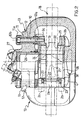
- Figure 1 shows an exploded perspective view of the bracket and caliper body assembly of a floating disc brake to which the present invention refers;
- Figure 2 shows a view from above in partial cross-section of a known type of floating disc brake, without the device of the present invention;
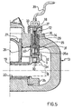
- Figure 3 shows a schematic cross-section through one half of a brake, such as the one in Figure 2, modified to include the pad wear warning device according to the invention, this device being shown in the position assumed when the pads are not yet worn;
- Figure 4 shows the same cross-section as in Figure 3 but with the warning device in the position assumed when the pads are partly worn;
- Figure 5 shows the same cross-section as in Figures 3 and 4 but with the warning device in the position assumed when the pads have reached their maximum permitted wear.
-
- With reference to the above figures, the numeral 1 denotes the brake bracket as a whole which, in its known version, consists of two
yokes 2 and 3, each shaped like an upturned U and lying in its own plane set a certain distance apart from each other. Each yoke has acrosspiece legs - The
yokes 2 and 3 are connected together by rod-like members 4 and 5 which are made in one piece with the pairs oflegs - The
legs - Another pair of tapped
holes 8 and 9, formed in thelegs threaded ends 10a ofcorresponding screws 10, the shanks of which pass longitudinally through an associatedtubular element 11. Thehead 10b of thescrew 10 engages in theend 11a of thetubular element 11, forming a unit referred to as a guide pin which is rigidly fixed to the bracket 1. Each guide pin is housed in acorresponding hole 12 formed in the caliper body, which is denoted as a whole by thereference 13 and is formed by a rectangular frame havingopposite sides - The
caliper body 13 is fitted on the bracket 1 and is connected thereto by means of the pair ofguide pins 11 which are slidably housed in theholes 12. - As may be seen in Figure 2 especially, the bracket 1 straddles the
disc 18 which is perpendicular to the longitudinal axes of theguide pins 11 and of theircorresponding holes 12. - The same bracket 1 supports the pair of
opposing pads - One end of a
leaf spring 21 is anchored to thepin 22 engaged in thelugs 23, while its other end is inserted underneath thecrosspiece 3a of the yoke 3. - At an intermediate point along its axial length the
spring 21 has twobent wings pads - The
pad 19 is therefore elastically pushed against the end of thehydraulic piston 26, operating inside thecylinder 27 formed in thecaliper body 13, in itsside 17. - The opposing
pad 20, on the other hand, is pressed against thewall 28 of theside 16 of the saidcaliper body 13. - Within the framework of a structure such as the one described hitherto, according to the present invention, one of the
tubular elements 11 and itsscrew 10, as shown in Figure 3, is replaced by acylindrical body 29 fitted with a threadedspigot 30 which engages in the tappedhole 9 in theleg 3c of the bracket 1. - This
cylindrical body 29, which is housed in one of the throughholes 12 in thecaliper body 13, together with its threadedspigot 30, performs the same function with respect to thecaliper body 13 as aguide pin 11. - It also has an
axial cavity 31 which is closed at thebottom 32 and open at theopposite end 33 which projects out of thehole 12. - According to the present invention, the said
axial cavity 31 houses a linear electrical transducer, known per se, which comprises a first rod-like element 34 and a second rod-like element 35, the movablefree end 35a of which is constantly pressed against thebottom 32 by a spring denoted schematically by thereference 36. - The
end 37 of the first rod-like element 34 of the transducer, on the other hand, is rigidly but removably fixed to thecaliper body 13, for example by means of anelastic cap 38. - This cap can be replaced by other equivalent means, for example screw means.
- The electrical signal derived from the transducer is picked up by the
cable 39 and transmitted to a computer (not shown). - A
flexible bellows 40 surrounds that part of thecylindrical body 29 that projects out of thehole 12 in order to protect against dust and dirt. - As is known, by actuating the brake lever, pressure is generated in the hydraulic system which terminates at the
cylinder 27 which, via thepiston 26, presses thepad 19 against the side of thedisc 18. As a result of the reaction force, transmitted via thecaliper body 13, the pad 20 - on which thewall 28 of theside 16 of thecaliper body 13 acts - is simultaneously pressed against the disc, thereby producing the braking action. - When the brake lever is released, the
pads disc 18. - As the friction material of the
pads disc 18 and consequently causing a corresponding displacement of thecaliper body 13 with respect to theguide pin 11. - In order to measure the state of wear of the
pads caliper body 13 with respect to thecylinder 29, which is integral with the bracket 1, as the thickness of thepad 20 gradually wears down and as the latter therefore gets closer and closer to thedisc 18. - This displacement is measured by the
free end 35a of the second rod-like element 35 of the transducer which is held in constant contact with thebottom 32 of thecylindrical element 29 which is connected with the bracket 1. - The electrical signal generated is picked up via the
cable 39. It allows the state of wear of thepad 20 to be evaluated and its remaining working life to be calculated, ultimately giving the mileage the vehicle can still travel on the remaining pad thickness. - The invention can be subject to numerous variations, including having the transducer in the form of a wiper type potentiometer.
- Figures 3, 4 and 5 show the successive positions assumed by the device as the pad 2.0 wears down.
- As may be deduced from the above description, the warning device according to the invention is contained within the overall dimensions of the
caliper body 13, with practically only thecable 39 extending outside them. - It does not therefore obstruct replacement of the
pads - Furthermore, positioning the transducer inside the
hole 12 gives the device the maximum degree of protection.
Claims (5)
- Floating caliper for disc brakes of vehicle wheels, said floating caliper comprising a caliper body (13) axially slidable by means of at least one hole (12) on at least one guide pin (10, 11), one end of which is rigidly connectable, directly or indirectly, to the wheel stub axle, the axis of the at least one guide pin and of the corresponding hole in the caliper body being perpendicular to the plane of the brake disc (18), a pair of pads (19, 20) positioned so that they straddle the disc (18), and a hydraulic piston (26) which acts directly on one (19) of the said pads and indirectly on the other pad (20), via the said caliper body (13), including further a pad wear indicating device positioned between a point connected with the said guide pin (10,11) and a point connected with the said caliper body (13), characterized in that said pad wear indicating device comprises a linear electrical displacement transducer (34, 35) housed inside an axial cavity (31) defined in a cylindrical element (29) that also fulfills the function of one of the guide pins (10,11).
- Floating caliper according to claim 1, wherein said linear electrical displacement transducer comprises a first rod-like element (34) having one end (37) connectable with the said caliper body (13), and a second rod-like element (35) which can slide axially with respect to the first rod-like element and which has a free end (35a) elastically held in contact with the bottom (32) of said axial cavity (31) of the cylindrical element (29).
- Floating caliper according to claim 2, wherein the one end (37) of the first rod-like element (34) is rigidly but removably fixable to the caliper body (13), preferably by screw means or by an elastic cap (38).
- Floating caliper according to any of the preceding claims, comprising a cable (39) for transmitting the signal from the transducer (34, 35) to a computer.
- Pad wear indicating device which is suitable for a so-called floating caliper used in disc brakes of vehicle wheels, wherein said floating caliper comprises:wherein said pad wear indicating device is positionable between a point connected with the said guide pin (10, 11) and a point connected with the said caliper body (13), characterized in that said pad wear indicating device comprises a linear electrical displacement transducer (34, 35) housed inside an axial cavity (31) defined in a cylindrical element (29) which is suitable to perform the same function with respect to the caliper body (13) as one of the guide pins (10, 11).a caliper body (13) axially slidable by means of at least one hole (12) on at least one guide pin (10, 11), one end of which is rigidly connectable, directly or indirectly, to the wheel stub axle, the axis of the guide pin and of the corresponding hole in the caliper body being perpendicular to the plane of the brake disc (18),a pair of pads (19, 20) positioned so that they straddle the disc (18),a hydraulic piston (26) which acts directly on one (19) of the said pads and indirectly on the other pad (20), via the said caliper body (13),
Priority Applications (4)
| Application Number | Priority Date | Filing Date | Title |
|---|---|---|---|
| EP98830482A EP0978665B1 (en) | 1998-08-05 | 1998-08-05 | Device for indicating lining wear in floating caliper disc brakes |
| DE69824408T DE69824408T2 (en) | 1998-08-05 | 1998-08-05 | Device for indicating the lining wear of floating caliper disc brakes |
| US09/361,745 US6272914B1 (en) | 1998-08-05 | 1999-07-27 | Device for indicating caliper pad wear in disc brakes |
| JP22105699A JP4387506B2 (en) | 1998-08-05 | 1999-08-04 | A device to display caliper pad wear during disc brakes |
Applications Claiming Priority (2)
| Application Number | Priority Date | Filing Date | Title |
|---|---|---|---|
| EP98830482A EP0978665B1 (en) | 1998-08-05 | 1998-08-05 | Device for indicating lining wear in floating caliper disc brakes |
| US09/361,745 US6272914B1 (en) | 1998-08-05 | 1999-07-27 | Device for indicating caliper pad wear in disc brakes |
Publications (2)
| Publication Number | Publication Date |
|---|---|
| EP0978665A1 EP0978665A1 (en) | 2000-02-09 |
| EP0978665B1 true EP0978665B1 (en) | 2004-06-09 |
Family
ID=26152166
Family Applications (1)
| Application Number | Title | Priority Date | Filing Date |
|---|---|---|---|
| EP98830482A Expired - Lifetime EP0978665B1 (en) | 1998-08-05 | 1998-08-05 | Device for indicating lining wear in floating caliper disc brakes |
Country Status (3)
| Country | Link |
|---|---|
| US (1) | US6272914B1 (en) |
| EP (1) | EP0978665B1 (en) |
| JP (1) | JP4387506B2 (en) |
Cited By (1)
| Publication number | Priority date | Publication date | Assignee | Title |
|---|---|---|---|---|
| EP2831447B1 (en) | 2012-03-26 | 2017-11-01 | KNORR-BREMSE Systeme für Nutzfahrzeuge GmbH | Floating-caliper disk brake of a motor vehicle |
Families Citing this family (35)
| Publication number | Priority date | Publication date | Assignee | Title |
|---|---|---|---|---|
| US6460659B1 (en) * | 2000-12-07 | 2002-10-08 | Caterpillar Inc | Brake wear indicator |
| US6637262B2 (en) * | 2001-11-02 | 2003-10-28 | Delphi Technologies, Inc. | Electrical wear sensor for disc brake |
| US6659233B2 (en) | 2001-12-04 | 2003-12-09 | Hydro-Aire, Inc. | System and method for aircraft braking system usage monitoring |
| SE526946C2 (en) | 2003-06-13 | 2005-11-22 | Haldex Brake Prod Ab | Sensor system |
| DE10356801B3 (en) * | 2003-12-04 | 2005-05-25 | Wabco Radbremsen Gmbh | Disk brake comprises a monitoring device having a measuring element that can be displaced relative to a caliper and is supported on an end surface of a pressure screw facing away from a brake disk |
| US20050267596A1 (en) * | 2004-05-03 | 2005-12-01 | Fulfillium, Inc. A Delaware Corporation | Devices and systems for gastric volume control |
| US7175006B2 (en) * | 2004-05-18 | 2007-02-13 | Bendix Spicer Foundation Brake Llc | Apparatus and method for sensing disc brake actuator position |
| US8070807B2 (en) * | 2004-11-19 | 2011-12-06 | Fulfillium, Inc. | Wireless breach detection |
| US9456915B2 (en) | 2004-11-19 | 2016-10-04 | Fulfilium, Inc. | Methods, devices, and systems for obesity treatment |
| US7607519B1 (en) * | 2005-08-31 | 2009-10-27 | Douglas Keegan | Hand controlled stopping device for a camera dolly |
| GB0608956D0 (en) * | 2006-05-05 | 2006-06-14 | Meritor Heavy Vehicle Braking | Disc brake wear aduster |
| JP2008222108A (en) * | 2007-03-14 | 2008-09-25 | Yamaha Motor Co Ltd | Replacement time guidance device to guide the replacement time of consumables |
| WO2009126067A1 (en) * | 2008-04-08 | 2009-10-15 | Volvo Construction Equipment Ab | A brake for a work machine, a wheel hub unit and a work machine |
| US8717159B2 (en) | 2010-03-15 | 2014-05-06 | Jamie Bishop Todd | Vehicle brake monitoring system and method |
| DE202010015910U1 (en) * | 2010-11-26 | 2011-02-24 | Haldex Brake Products Ab | Brake monitoring device for a disc brake |
| DE202012001863U1 (en) * | 2012-02-22 | 2012-03-19 | Haldex Brake Products Ab | Disc brake and sensor device for this |
| US8973240B2 (en) | 2012-08-17 | 2015-03-10 | Bendix Spicer Foundation Brake Llc | Disc brake pad mounting and retention system and method |
| US8973720B2 (en) * | 2012-08-17 | 2015-03-10 | Bendix Spicer Foundation Brake Llc | Disc brake pad mounting and retention system and method |
| CN103470663B (en) * | 2013-09-11 | 2015-10-28 | 开天传动技术(上海)有限公司 | Wear sensor for friction plate of fan yaw brake |
| WO2015050638A1 (en) * | 2013-10-02 | 2015-04-09 | Bendix Spicer Foundation Brake Llc | Disc brake pad mounting and retention system and method |
| JP6233670B2 (en) * | 2014-06-25 | 2017-11-22 | 日立オートモティブシステムズ株式会社 | Disc brake |
| TWI664362B (en) * | 2014-08-29 | 2019-07-01 | 日商日立汽車系統股份有限公司 | Disc brake |
| US9279468B1 (en) * | 2014-12-09 | 2016-03-08 | Arvinmeritor Technology, Llc | Brake assembly |
| US9618067B2 (en) | 2014-12-09 | 2017-04-11 | Arvinmeritor Technology, Llc | Brake assembly and method of control |
| US10233984B2 (en) * | 2017-04-24 | 2019-03-19 | Ford Global Technologies, Llc | Multiple function brake caliper guide pin |
| EP3492768B1 (en) * | 2017-11-29 | 2021-02-24 | Meritor Heavy Vehicle Braking Systems (UK) Limited | Caliper guide assembly |
| IT201800006577A1 (en) | 2018-06-22 | 2019-12-22 | Disc brake caliper body | |
| US10865840B2 (en) * | 2018-10-25 | 2020-12-15 | Akebono Brake Industry Co., Ltd. | Support hidden sliding caliper |
| US10781872B2 (en) | 2018-10-25 | 2020-09-22 | Akebono Brake Industry Co., Ltd. | Floating collar and one-piece guide pin and bolt assembly |
| EP3872360A1 (en) * | 2020-02-28 | 2021-09-01 | Meritor Heavy Vehicle Braking Systems (UK) Limited | Caliper guide assembly |
| EP3978777B1 (en) * | 2020-09-30 | 2023-11-29 | ZF CV Systems Europe BV | Brake pad of a vehicle brake, vehicle brake and method for assembling a vehicle brake |
| IT202000027200A1 (en) * | 2020-11-13 | 2022-05-13 | Brembo Spa | PROTECTIVE CAP FOR FLOATING CLAMP GUIDES |
| CN112664594B (en) * | 2020-12-18 | 2025-06-24 | 常州机电职业技术学院 | A caliper assembly with friction plate wear monitoring function and wear alarm, vibration detection and brake failure compensation method thereof |
| US11648927B2 (en) * | 2021-06-11 | 2023-05-16 | Arvinmeritor Technology, Llc | Disc brake assembly having a sensor assembly |
| DE102023205092A1 (en) * | 2023-05-31 | 2024-12-05 | Hl Mando Corporation | Brake arrangement with device for generating a warning signal |
Family Cites Families (8)
| Publication number | Priority date | Publication date | Assignee | Title |
|---|---|---|---|---|
| GB2029528B (en) * | 1978-07-19 | 1982-11-10 | Lucas Industries Ltd | Brake wear indicator |
| US4280594A (en) * | 1979-07-17 | 1981-07-28 | Lucas Industries Limited | Brake wear indicator |
| GB2177170B (en) * | 1985-06-25 | 1989-07-12 | Gen Motors France | Disc brake assembly having an electrical lining wear indicator |
| DE3903306A1 (en) * | 1989-02-04 | 1990-08-09 | Teves Gmbh Alfred | FRICTION LINING WARNING DEVICE |
| EP0623196B1 (en) * | 1992-01-28 | 1996-09-11 | ITT Automotive Europe GmbH | Floating caliper disc brake with expansion springs for the brake shoes |
| FR2716509B1 (en) * | 1994-01-19 | 1996-04-12 | Alliedsignal Automotive Espana | Disc brake with increased safety. |
| DE19600819A1 (en) * | 1996-01-11 | 1997-07-17 | Perrot Bremsen Gmbh | Wear monitoring device |
| US5697472A (en) * | 1996-02-09 | 1997-12-16 | Caterpillar Inc. | Wear indicator |
-
1998
- 1998-08-05 EP EP98830482A patent/EP0978665B1/en not_active Expired - Lifetime
-
1999
- 1999-07-27 US US09/361,745 patent/US6272914B1/en not_active Expired - Lifetime
- 1999-08-04 JP JP22105699A patent/JP4387506B2/en not_active Expired - Fee Related
Cited By (1)
| Publication number | Priority date | Publication date | Assignee | Title |
|---|---|---|---|---|
| EP2831447B1 (en) | 2012-03-26 | 2017-11-01 | KNORR-BREMSE Systeme für Nutzfahrzeuge GmbH | Floating-caliper disk brake of a motor vehicle |
Also Published As
| Publication number | Publication date |
|---|---|
| JP4387506B2 (en) | 2009-12-16 |
| US6272914B1 (en) | 2001-08-14 |
| EP0978665A1 (en) | 2000-02-09 |
| JP2000065108A (en) | 2000-03-03 |
Similar Documents
| Publication | Publication Date | Title |
|---|---|---|
| EP0978665B1 (en) | Device for indicating lining wear in floating caliper disc brakes | |
| US4658936A (en) | Brake temperature and wear indicator | |
| US5699880A (en) | Brake adjustment indicator | |
| CN111412235B (en) | System and method for monitoring abrasion of friction plate of floating brake vehicle | |
| CN108730373B (en) | Multifunctional brake caliper guide pin | |
| US3997033A (en) | Cam operated disc brake | |
| CN110462246B (en) | Disc brake apparatus for vehicle including brake lining wear detection device | |
| US20040159512A1 (en) | Disc brake | |
| EP3556624A1 (en) | Improved brake wear monitoring | |
| EP1937993B1 (en) | A rail vehicle brake unit | |
| JP2008510944A (en) | Aircraft wheel brake | |
| GB1602846A (en) | Sliding caliper disc brake | |
| JP3543821B2 (en) | Hydraulic vehicle clutch equipped with wear indicating means | |
| JPS6146689B2 (en) | ||
| EP0670972B1 (en) | Brake wear sensor | |
| WO2023100071A1 (en) | "caliper and support assembly, and method" | |
| CA1039624A (en) | Auxiliary brake lever | |
| KR100559832B1 (en) | Brake Pad Indicator System | |
| CN219013237U (en) | Sensor for detecting abrasion loss of brake pad | |
| JP2002372082A (en) | Abrasion quantity measuring device for abrasion material for brake | |
| CN219954027U (en) | Disc brake caliper | |
| KR20220073457A (en) | Monitoring unit for brake system and brake pad assembly having the same | |
| CN221340567U (en) | Monitoring equipment, brake systems and vehicles | |
| JPH0244110Y2 (en) | ||
| KR200200497Y1 (en) | Apparatus for detecting the defacement on brake pad for vehicle |
Legal Events
| Date | Code | Title | Description |
|---|---|---|---|
| PUAI | Public reference made under article 153(3) epc to a published international application that has entered the european phase |
Free format text: ORIGINAL CODE: 0009012 |
|
| 17P | Request for examination filed |
Effective date: 19990827 |
|
| AK | Designated contracting states |
Kind code of ref document: A1 Designated state(s): DE FR GB IT |
|
| AX | Request for extension of the european patent |
Free format text: AL;LT;LV;MK;RO;SI |
|
| AKX | Designation fees paid |
Free format text: DE FR GB IT |
|
| 17Q | First examination report despatched |
Effective date: 20020313 |
|
| GRAP | Despatch of communication of intention to grant a patent |
Free format text: ORIGINAL CODE: EPIDOSNIGR1 |
|
| GRAS | Grant fee paid |
Free format text: ORIGINAL CODE: EPIDOSNIGR3 |
|
| GRAA | (expected) grant |
Free format text: ORIGINAL CODE: 0009210 |
|
| AK | Designated contracting states |
Kind code of ref document: B1 Designated state(s): DE FR GB IT |
|
| REG | Reference to a national code |
Ref country code: GB Ref legal event code: FG4D |
|
| REF | Corresponds to: |
Ref document number: 69824408 Country of ref document: DE Date of ref document: 20040715 Kind code of ref document: P |
|
| ET | Fr: translation filed | ||
| PLBE | No opposition filed within time limit |
Free format text: ORIGINAL CODE: 0009261 |
|
| STAA | Information on the status of an ep patent application or granted ep patent |
Free format text: STATUS: NO OPPOSITION FILED WITHIN TIME LIMIT |
|
| 26N | No opposition filed |
Effective date: 20050310 |
|
| PGFP | Annual fee paid to national office [announced via postgrant information from national office to epo] |
Ref country code: GB Payment date: 20120821 Year of fee payment: 15 |
|
| PGFP | Annual fee paid to national office [announced via postgrant information from national office to epo] |
Ref country code: FR Payment date: 20120919 Year of fee payment: 15 |
|
| GBPC | Gb: european patent ceased through non-payment of renewal fee |
Effective date: 20130805 |
|
| REG | Reference to a national code |
Ref country code: FR Ref legal event code: ST Effective date: 20140430 |
|
| PG25 | Lapsed in a contracting state [announced via postgrant information from national office to epo] |
Ref country code: GB Free format text: LAPSE BECAUSE OF NON-PAYMENT OF DUE FEES Effective date: 20130805 |
|
| PG25 | Lapsed in a contracting state [announced via postgrant information from national office to epo] |
Ref country code: FR Free format text: LAPSE BECAUSE OF NON-PAYMENT OF DUE FEES Effective date: 20130902 |
|
| PGFP | Annual fee paid to national office [announced via postgrant information from national office to epo] |
Ref country code: IT Payment date: 20170808 Year of fee payment: 20 |
|
| PGFP | Annual fee paid to national office [announced via postgrant information from national office to epo] |
Ref country code: DE Payment date: 20171030 Year of fee payment: 20 |
|
| REG | Reference to a national code |
Ref country code: DE Ref legal event code: R071 Ref document number: 69824408 Country of ref document: DE |