EP2830757B1 - Methode zur herstellung eines photokatalysators - Google Patents
Methode zur herstellung eines photokatalysators Download PDFInfo
- Publication number
- EP2830757B1 EP2830757B1 EP13734139.2A EP13734139A EP2830757B1 EP 2830757 B1 EP2830757 B1 EP 2830757B1 EP 13734139 A EP13734139 A EP 13734139A EP 2830757 B1 EP2830757 B1 EP 2830757B1
- Authority
- EP
- European Patent Office
- Prior art keywords
- titanium
- photocatalyst
- cathode
- anode
- mfc
- Prior art date
- Legal status (The legal status is an assumption and is not a legal conclusion. Google has not performed a legal analysis and makes no representation as to the accuracy of the status listed.)
- Not-in-force
Links
Images





Classifications
-
- C—CHEMISTRY; METALLURGY
- C02—TREATMENT OF WATER, WASTE WATER, SEWAGE, OR SLUDGE
- C02F—TREATMENT OF WATER, WASTE WATER, SEWAGE, OR SLUDGE
- C02F1/00—Treatment of water, waste water, or sewage
- C02F1/30—Treatment of water, waste water, or sewage by irradiation
- C02F1/32—Treatment of water, waste water, or sewage by irradiation with ultraviolet light
- C02F1/325—Irradiation devices or lamp constructions
-
- B—PERFORMING OPERATIONS; TRANSPORTING
- B01—PHYSICAL OR CHEMICAL PROCESSES OR APPARATUS IN GENERAL
- B01J—CHEMICAL OR PHYSICAL PROCESSES, e.g. CATALYSIS OR COLLOID CHEMISTRY; THEIR RELEVANT APPARATUS
- B01J21/00—Catalysts comprising the elements, oxides, or hydroxides of magnesium, boron, aluminium, carbon, silicon, titanium, zirconium, or hafnium
- B01J21/06—Silicon, titanium, zirconium or hafnium; Oxides or hydroxides thereof
- B01J21/063—Titanium; Oxides or hydroxides thereof
-
- B—PERFORMING OPERATIONS; TRANSPORTING
- B01—PHYSICAL OR CHEMICAL PROCESSES OR APPARATUS IN GENERAL
- B01J—CHEMICAL OR PHYSICAL PROCESSES, e.g. CATALYSIS OR COLLOID CHEMISTRY; THEIR RELEVANT APPARATUS
- B01J35/00—Catalysts, in general, characterised by their form or physical properties
- B01J35/30—Catalysts, in general, characterised by their form or physical properties characterised by their physical properties
-
- B—PERFORMING OPERATIONS; TRANSPORTING
- B01—PHYSICAL OR CHEMICAL PROCESSES OR APPARATUS IN GENERAL
- B01J—CHEMICAL OR PHYSICAL PROCESSES, e.g. CATALYSIS OR COLLOID CHEMISTRY; THEIR RELEVANT APPARATUS
- B01J35/00—Catalysts, in general, characterised by their form or physical properties
- B01J35/30—Catalysts, in general, characterised by their form or physical properties characterised by their physical properties
- B01J35/39—Photocatalytic properties
-
- B—PERFORMING OPERATIONS; TRANSPORTING
- B01—PHYSICAL OR CHEMICAL PROCESSES OR APPARATUS IN GENERAL
- B01J—CHEMICAL OR PHYSICAL PROCESSES, e.g. CATALYSIS OR COLLOID CHEMISTRY; THEIR RELEVANT APPARATUS
- B01J35/00—Catalysts, in general, characterised by their form or physical properties
- B01J35/30—Catalysts, in general, characterised by their form or physical properties characterised by their physical properties
- B01J35/391—Physical properties of the active metal ingredient
- B01J35/395—Thickness of the active catalytic layer
-
- B—PERFORMING OPERATIONS; TRANSPORTING
- B01—PHYSICAL OR CHEMICAL PROCESSES OR APPARATUS IN GENERAL
- B01J—CHEMICAL OR PHYSICAL PROCESSES, e.g. CATALYSIS OR COLLOID CHEMISTRY; THEIR RELEVANT APPARATUS
- B01J35/00—Catalysts, in general, characterised by their form or physical properties
- B01J35/50—Catalysts, in general, characterised by their form or physical properties characterised by their shape or configuration
- B01J35/56—Foraminous structures having flow-through passages or channels, e.g. grids or three-dimensional [3D] monoliths
-
- B—PERFORMING OPERATIONS; TRANSPORTING
- B01—PHYSICAL OR CHEMICAL PROCESSES OR APPARATUS IN GENERAL
- B01J—CHEMICAL OR PHYSICAL PROCESSES, e.g. CATALYSIS OR COLLOID CHEMISTRY; THEIR RELEVANT APPARATUS
- B01J35/00—Catalysts, in general, characterised by their form or physical properties
- B01J35/50—Catalysts, in general, characterised by their form or physical properties characterised by their shape or configuration
- B01J35/58—Fabrics or filaments
-
- B—PERFORMING OPERATIONS; TRANSPORTING
- B01—PHYSICAL OR CHEMICAL PROCESSES OR APPARATUS IN GENERAL
- B01J—CHEMICAL OR PHYSICAL PROCESSES, e.g. CATALYSIS OR COLLOID CHEMISTRY; THEIR RELEVANT APPARATUS
- B01J37/00—Processes, in general, for preparing catalysts; Processes, in general, for activation of catalysts
- B01J37/02—Impregnation, coating or precipitation
- B01J37/0215—Coating
- B01J37/0225—Coating of metal substrates
- B01J37/0226—Oxidation of the substrate, e.g. anodisation
-
- B—PERFORMING OPERATIONS; TRANSPORTING
- B01—PHYSICAL OR CHEMICAL PROCESSES OR APPARATUS IN GENERAL
- B01J—CHEMICAL OR PHYSICAL PROCESSES, e.g. CATALYSIS OR COLLOID CHEMISTRY; THEIR RELEVANT APPARATUS
- B01J37/00—Processes, in general, for preparing catalysts; Processes, in general, for activation of catalysts
- B01J37/34—Irradiation by, or application of, electric, magnetic or wave energy, e.g. ultrasonic waves ; Ionic sputtering; Flame or plasma spraying; Particle radiation
- B01J37/348—Electrochemical processes, e.g. electrochemical deposition or anodisation
-
- C—CHEMISTRY; METALLURGY
- C02—TREATMENT OF WATER, WASTE WATER, SEWAGE, OR SLUDGE
- C02F—TREATMENT OF WATER, WASTE WATER, SEWAGE, OR SLUDGE
- C02F1/00—Treatment of water, waste water, or sewage
- C02F1/30—Treatment of water, waste water, or sewage by irradiation
- C02F1/32—Treatment of water, waste water, or sewage by irradiation with ultraviolet light
-
- C—CHEMISTRY; METALLURGY
- C02—TREATMENT OF WATER, WASTE WATER, SEWAGE, OR SLUDGE
- C02F—TREATMENT OF WATER, WASTE WATER, SEWAGE, OR SLUDGE
- C02F1/00—Treatment of water, waste water, or sewage
- C02F1/72—Treatment of water, waste water, or sewage by oxidation
-
- C—CHEMISTRY; METALLURGY
- C02—TREATMENT OF WATER, WASTE WATER, SEWAGE, OR SLUDGE
- C02F—TREATMENT OF WATER, WASTE WATER, SEWAGE, OR SLUDGE
- C02F1/00—Treatment of water, waste water, or sewage
- C02F1/72—Treatment of water, waste water, or sewage by oxidation
- C02F1/725—Treatment of water, waste water, or sewage by oxidation by catalytic oxidation
-
- C—CHEMISTRY; METALLURGY
- C02—TREATMENT OF WATER, WASTE WATER, SEWAGE, OR SLUDGE
- C02F—TREATMENT OF WATER, WASTE WATER, SEWAGE, OR SLUDGE
- C02F9/00—Multistage treatment of water, waste water or sewage
-
- C—CHEMISTRY; METALLURGY
- C25—ELECTROLYTIC OR ELECTROPHORETIC PROCESSES; APPARATUS THEREFOR
- C25D—PROCESSES FOR THE ELECTROLYTIC OR ELECTROPHORETIC PRODUCTION OF COATINGS; ELECTROFORMING; APPARATUS THEREFOR
- C25D11/00—Electrolytic coating by surface reaction, i.e. forming conversion layers
- C25D11/02—Anodisation
- C25D11/024—Anodisation under pulsed or modulated current or potential
-
- C—CHEMISTRY; METALLURGY
- C25—ELECTROLYTIC OR ELECTROPHORETIC PROCESSES; APPARATUS THEREFOR
- C25D—PROCESSES FOR THE ELECTROLYTIC OR ELECTROPHORETIC PRODUCTION OF COATINGS; ELECTROFORMING; APPARATUS THEREFOR
- C25D11/00—Electrolytic coating by surface reaction, i.e. forming conversion layers
- C25D11/02—Anodisation
- C25D11/026—Anodisation with spark discharge
-
- C—CHEMISTRY; METALLURGY
- C25—ELECTROLYTIC OR ELECTROPHORETIC PROCESSES; APPARATUS THEREFOR
- C25D—PROCESSES FOR THE ELECTROLYTIC OR ELECTROPHORETIC PRODUCTION OF COATINGS; ELECTROFORMING; APPARATUS THEREFOR
- C25D11/00—Electrolytic coating by surface reaction, i.e. forming conversion layers
- C25D11/02—Anodisation
- C25D11/26—Anodisation of refractory metals or alloys based thereon
-
- H—ELECTRICITY
- H01—ELECTRIC ELEMENTS
- H01M—PROCESSES OR MEANS, e.g. BATTERIES, FOR THE DIRECT CONVERSION OF CHEMICAL ENERGY INTO ELECTRICAL ENERGY
- H01M8/00—Fuel cells; Manufacture thereof
- H01M8/16—Biochemical fuel cells, i.e. cells in which microorganisms function as catalysts
-
- B—PERFORMING OPERATIONS; TRANSPORTING
- B01—PHYSICAL OR CHEMICAL PROCESSES OR APPARATUS IN GENERAL
- B01J—CHEMICAL OR PHYSICAL PROCESSES, e.g. CATALYSIS OR COLLOID CHEMISTRY; THEIR RELEVANT APPARATUS
- B01J2235/00—Indexing scheme associated with group B01J35/00, related to the analysis techniques used to determine the catalysts form or properties
-
- B—PERFORMING OPERATIONS; TRANSPORTING
- B01—PHYSICAL OR CHEMICAL PROCESSES OR APPARATUS IN GENERAL
- B01J—CHEMICAL OR PHYSICAL PROCESSES, e.g. CATALYSIS OR COLLOID CHEMISTRY; THEIR RELEVANT APPARATUS
- B01J2235/00—Indexing scheme associated with group B01J35/00, related to the analysis techniques used to determine the catalysts form or properties
- B01J2235/15—X-ray diffraction
-
- B—PERFORMING OPERATIONS; TRANSPORTING
- B01—PHYSICAL OR CHEMICAL PROCESSES OR APPARATUS IN GENERAL
- B01J—CHEMICAL OR PHYSICAL PROCESSES, e.g. CATALYSIS OR COLLOID CHEMISTRY; THEIR RELEVANT APPARATUS
- B01J35/00—Catalysts, in general, characterised by their form or physical properties
- B01J35/60—Catalysts, in general, characterised by their form or physical properties characterised by their surface properties or porosity
- B01J35/64—Pore diameter
- B01J35/651—50-500 nm
-
- B—PERFORMING OPERATIONS; TRANSPORTING
- B01—PHYSICAL OR CHEMICAL PROCESSES OR APPARATUS IN GENERAL
- B01J—CHEMICAL OR PHYSICAL PROCESSES, e.g. CATALYSIS OR COLLOID CHEMISTRY; THEIR RELEVANT APPARATUS
- B01J35/00—Catalysts, in general, characterised by their form or physical properties
- B01J35/60—Catalysts, in general, characterised by their form or physical properties characterised by their surface properties or porosity
- B01J35/64—Pore diameter
- B01J35/653—500-1000 nm
-
- B—PERFORMING OPERATIONS; TRANSPORTING
- B01—PHYSICAL OR CHEMICAL PROCESSES OR APPARATUS IN GENERAL
- B01J—CHEMICAL OR PHYSICAL PROCESSES, e.g. CATALYSIS OR COLLOID CHEMISTRY; THEIR RELEVANT APPARATUS
- B01J35/00—Catalysts, in general, characterised by their form or physical properties
- B01J35/60—Catalysts, in general, characterised by their form or physical properties characterised by their surface properties or porosity
- B01J35/64—Pore diameter
- B01J35/657—Pore diameter larger than 1000 nm
-
- C—CHEMISTRY; METALLURGY
- C02—TREATMENT OF WATER, WASTE WATER, SEWAGE, OR SLUDGE
- C02F—TREATMENT OF WATER, WASTE WATER, SEWAGE, OR SLUDGE
- C02F2101/00—Nature of the contaminant
- C02F2101/30—Organic compounds
-
- C—CHEMISTRY; METALLURGY
- C02—TREATMENT OF WATER, WASTE WATER, SEWAGE, OR SLUDGE
- C02F—TREATMENT OF WATER, WASTE WATER, SEWAGE, OR SLUDGE
- C02F2305/00—Use of specific compounds during water treatment
- C02F2305/10—Photocatalysts
-
- C—CHEMISTRY; METALLURGY
- C02—TREATMENT OF WATER, WASTE WATER, SEWAGE, OR SLUDGE
- C02F—TREATMENT OF WATER, WASTE WATER, SEWAGE, OR SLUDGE
- C02F3/00—Biological treatment of water, waste water, or sewage
- C02F3/005—Combined electrochemical biological processes
-
- Y—GENERAL TAGGING OF NEW TECHNOLOGICAL DEVELOPMENTS; GENERAL TAGGING OF CROSS-SECTIONAL TECHNOLOGIES SPANNING OVER SEVERAL SECTIONS OF THE IPC; TECHNICAL SUBJECTS COVERED BY FORMER USPC CROSS-REFERENCE ART COLLECTIONS [XRACs] AND DIGESTS
- Y02—TECHNOLOGIES OR APPLICATIONS FOR MITIGATION OR ADAPTATION AGAINST CLIMATE CHANGE
- Y02E—REDUCTION OF GREENHOUSE GAS [GHG] EMISSIONS, RELATED TO ENERGY GENERATION, TRANSMISSION OR DISTRIBUTION
- Y02E60/00—Enabling technologies; Technologies with a potential or indirect contribution to GHG emissions mitigation
- Y02E60/30—Hydrogen technology
- Y02E60/50—Fuel cells
Definitions
- the present invention relates to a method of manufacturing a photocatalyst. More particularly, but not exclusively, embodiments of the present invention relate to a method of manufacturing a high surface area TiO 2 photocatalyst formed by electrolytic discharge oxidation (EDO) of a substrate comprising titanium.
- EEO electrolytic discharge oxidation
- the process can achieve a coating having over 96% of the anatase phase, and thereby providing surface area enhancements.
- Embodiments of the invention may be used to make a microbial fuel cell for treating water, and in particular to make a fuel cell in which both photocatalytic treatment (known as "Advanced Oxidation") and microbial treatment can be employed.
- This could form an assembly for photocatalytic treatment of water which can be incorporated into a microbial fuel cell.
- the water which is treated could be for example be industrial wastewater, or could be ultra pure water in the electronics industry, from which micro contaminants can be removed.
- Advanced Oxidation can be defined as a chemical reaction influenced or initiated by light that removes electrons from a catalyst (such as titanium dioxide, TiO 2 ) and adds those electrons to an organic substrate.
- a catalyst such as titanium dioxide, TiO 2
- TiO 2 forms electron (-) and hole (+) pairs and has been shown to oxidize and reduce many organic molecules.
- an electron located in the conduction band is capable of reducing species A.
- a photon UV light
- the oxidizing power of such a hole is very high in TiO 2 , especially in the anatase phase which is generally more photocatalytically active than rutile or amorphous TiO 2
- valence band holes h vB +
- conduction band electrons e cB
- These charge carriers migrate to the surface of the semiconductor (TiO 2 ) and react by electron transfer with donors and acceptors adsorbed at this surface.
- aromatic compounds are degraded by hydroxyl radicals, formed by oxidation of adsorbed water molecules or surface bound hydroxyl groups.
- Industrial waste water contains many non-biodegradable organics, which make the application of microbial fuel cells for treatment of industrial wastewater very limited. Waste water treatment using TiO 2 as a photocatalyst has attracted a great deal of attention because of its high activity, chemical stability, robustness against photocorrosion, low toxicity, low pollution load, and availability at low cost i .
- the shortcomings of conventional powder catalysts include low efficiency of light use, difficulty of stirring during reaction and separation after reaction (usually using ultra-filtration), and low-concentration contamination near TiO 2 due to its low surface areai ii .
- the current methods used to perform TiO 2 photocatalysis also include the application of UV onto a TiO 2 surface coating in the presence of the target waste stream.
- Microbial fuel cells are becoming an attractive method for treatment of wastewater because they enable energy recovery and reduction of production of excess sludge.
- PEMs proton exchange membranes
- mediators limit the application of MFCs for treatment of wastewater. Transfer of protons through PEMs is difficult since PEMs get fouled due to suspended solids and soluble contaminants found in wastewater. Moreover, PEMs are expensive.
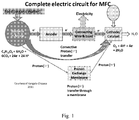
- MFC utilise a special type of bacteria (termed exoelectrogens) that are able to transfer electrons to an electron acceptor exogenously (outside the cell), thereby enabling the energy to be recovered as electrical energy utilising fuel cell technology (see Figure 1 ).
- exoelectrogenic microbes are only just being discovered, demonstrating high performance at ambient (15 - 35°C), high (50 - 60°C - thermophiles) and low ( ⁇ 15°C - psychrophiles) temperatures, and the ability to metabolise almost any organic matter (organic acids, carbohydrates, proteins, alcohols, cellulose, etc).
- MFC proton exchange membrane fuel cell
- PEMFC proton exchange membrane fuel cell
- the anode and cathode compartment were full of anolyte and catholyte, respectively.
- microorganisms oxidize the organic matters in wastewater to produce electrons and protons.
- the protons migrate from the anode compartment to the cathode compartment through the PEM, while the electrons pass through the external circuit to the cathode compartment.
- electron acceptors combine with protons and electrons vi .
- Oxygen is the most widely used cathodic electron acceptor in MFCs due to its unlimited availability in the environment and high redox potential.
- the unfavourable reaction kinetics of oxygen reduction on the surface of carbon electrodes and the low mass transfer coefficient of gaseous oxygen in catholyte severely hampers its application in MFCs viii .
- many soluble electron acceptors with high reduction rate on carbon electrodes have been adopted in MFCs, such as hydrogen peroxide, ferricyanide, permanganate and potassium persulfate.
- the MFC performance was still low due to the low reduction kinetics of these electron acceptors on the carbon electrodes, including their slow regeneration rate ix .
- EP 0 827 229 discloses a biofuel cell which can react with an electrode without a mediator.
- Graphite rods are used as electrodes, and the anode and cathode compartments are separated by a sintered glass.
- the electrodes may be formed from graphite felt and separated by a cation-exchange membrane.
- US 2005/0208343 discloses a mediator-less microbial fuel cell comprising a cathode compartment and an anode compartment which are separated with glass wool or glass beads, means for feeding air to the cathode compartment and means for feeding wastewater to the anode compartment.
- Graphite felt (which may be coated with a metal such as platinum) is used as an electrode of the cathode compartment.
- WO 2009/149309 discloses a microbial fuel cell having separate anode and cathode modules in which cation flow between the modules is enabled by a source stream rather than via a membrane.
- US 2011/160047 discloses titanium dioxide having an excellent photocatalytic activity and an excellent super-hydrophilic property by a simple procedure suitable for the production on an industrial scale.
- Rutile-type titanium dioxide having an excellent photocatalytic activity can be produced by carrying out the anodic oxidization of the surface of a base material comprising titanium or a titanium alloy by applying a voltage (e.g., a high voltage) or carrying out the anodic oxidation of the surface of the base material under high current density conditions.
- a film is produced on the surface of the base material by the anodic oxidation technique by applying a voltage or the anodic oxidization technique under high current density conditions, and the film is subjected to heat treatment, thereby producing rutile-type titanium dioxide having excellent crystallinity.
- US 6248235 discloses a photocatalytic oxidation purification system including an ultra violet light source and a filter that comprises a pleated wire mesh substrate with a nanophase metal oxide oxidation catalyst suspended on the substrate, wherein the catalyst is applied without an adhesive using an electromechanical plating process.
- a fluid containing organic contaminants is directed through the filter in the presence of ultra violet light from the light source, the catalyst oxidizes and decomposes the organic contaminants into environmentally harmless components.
- Methods of making the purification system including preparing a solution of catalyst and applying the catalyst without adhesive binding material to the filter substrate electromagnetically.
- the anodic oxide film is excellent in strength and adhesion to the titanium material, photocatalytic activity is stably exhibited by the titanium material thus obtained, and the titanium material is effectively used as building materials. Further, the titanium material having photocatalytic activity is easily obtained only by adding the fine grains having photocatalytic activity to the electrolytic bath and electrolyzing the material.
- JP 2008 302328 discloses a method for manufacturing a titanium oxide film-formed member, with which the titanium oxide film exhibiting adhesive strength even to the member having a comparatively large area can be formed uniformly and with good reproducibility by a simple and easy-to-handle constitution and to provide a water treatment apparatus using a photoelectrode obtained by this manufacturing method.
- a base body consisting of a titanium material is oxidized electrolytically in a solution of 0.1 mol/L nitric acid concentration to oxidize the surface of the base body and form the titanium oxide film.
- the titanium oxide film-formed base body is exposed to an atmosphere of 500°C and heat-treated to cause the titanium oxide film on the base body to have an anatase structure by thermal oxidation.
- the base body having the titanium oxide film of the anatase structure is used as a first electrode to constitute the water treatment apparatus.
- the water treatment apparatus has a pair of electrodes including the first electrode in the upper part of a water storage tank for storing the water to be treated. A bias voltage is applied between the pair of electrodes from a power unit. An ultraviolet illumination lamp is arranged above the first electrode.
- US 2010/047611 discloses a method of preparing a nanoporous titanium film including depositing a film of a mixture including titanium and one or more metals that are immiscible with the titanium on a substrate; and eliminating the one or more metals that are immiscible with the titanium selectively from the mixture by an electrochemical method.
- a method of preparing a nanoporous TiO 2 film includes depositing a film of a mixture including titanium and one or more metals that are immiscible with the titanium on a substrate; eliminating the one or more metals that are immiscible with the titanium selectively from the mixture by an electrochemical method; and oxidizing the titanium.
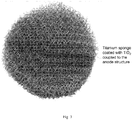
- the photocatalyst is a macroporous titanium dioxide structure. This may be formed by surface oxidation of any permeable structure that presents a titanium surface (such as a sponge woven from titanium metal wire). Thus, a high surface area of anatase can be achieved in a single, cohesive, flexible, and readily scaleable unit.
- the photocatalyst's structure may be optimised to give maximum exposure of the TiO 2 photocatalyst within the UV radiation attenuation length, and may fulfil additional functions of fluid flow management, and of UV shielding (e.g. of the microbes).
- the macroporous architecture may be woven, knitted, or configured to form a sponge or mesh by other means.
- the macroporous architecture may be formed from a perforated titanium sheet material.
- the titanium sheet material will comprise multiple perforations.
- the photocatalyst structure may also be optimised to give maximum exposure of the TiO 2 photocatalyst within a desired electromagnetic radiation attenuation range, such as within the attenuation length of any form of electromagnetic radiation, thereby matching the photocatalyst structure to suit a particular wavelength of electromagnetic radiation.
- the photocatalyst may comprise a compliant, cohesive, well-adhered and highly porous surface layer of the anatase phase of titanium dioxide, formed in a single step by the electrolytic oxidation of a titanium surface on a permeable, flexible, and electrically conductive substrate sponge structure.
- the titanium dioxide is formed by pulsed bi-polar electrolytic discharge oxidation of the titanium surface, exposing the growing oxide to an oxygen rich plasma at temperatures of over 3000 K for periods of 1 to 100 microseconds, so as to yield a rough and highly porous oxide layer with a specific surface area of over 5m 2 per gram of oxide, and a low stiffness (E ⁇ 50 GPa).
- the surface area may be over 10 m 2 per gram of oxide, and preferably, the surface area may be over 20 m 2 per gram of oxide, corresponding to a surface area enhancement of over 100 times.
- the titanium metal employed may preferably be of commercially pure grades (grades 1-4, e.g. commercially pure grade 2 titanium is 99.6% pure), so as to yield a high proportion of the anatase phase of TiO 2 (>90 Weight %) during pulsed bi-polar electrolytic discharge oxidation in a dilute alkaline electrolyte (comprising an alkaline metal phosphate at ⁇ 10 g per litre).
- pulsed bi-polar electrolytic discharge oxidation may be carried out in a dilute non-alkaline electrolyte.
- the photocatalyst may consist of reinforced metal wire, offering a flexible compliant architecture, which will conform to varied geometries. For instance, this allows the photocatalyst to be wrapped around elements such as UV radiation sources in a water purification system.
- the titanium oxide may be in the form of a permeable sponge structure which is used for fluid flow management in a water purification system.
- the electrically conductive substrate sponge structure can be used to electrically integrate the photocatalyst into an electrolytic cell.
- this photocatalyst benefits from the toughness and elasticity of the metal, and is a far more flexible and manageable structure for water purification applications than a powder-based photocatalyst or a more conventional porous ceramic. It may, for example, be wrapped around a tubular UV source.
- a conductive substrate for the photocatalyst provides a pathway for the extraction of electrons, which may be used to promote photocatalytic efficiency by reducing the likelihood of electron-hole recombination, and may thus be integrated into the anode structure.
- the anode for an electrolytic cell may consist either in part, or in its entirety, of such a porous Ti/TiO 2 sponge structure.
- JP9085099 describes anodising titanium and other metals as a means of creating a photocatalyst structure, but such a process results in amorphous TiO 2 , rather than the crystalline anatase form used in the present invention, and does not significantly enhance the surface area of the Ti structure.
- JP2003129290 and JP11100695 both seek to incorporate crystalline oxides into an anodically formed oxide by including a suspension of oxides in the anodising bath. Neither of these yields a high phase proportion of crystalline material.
- CN101856609 employs a thermal oxidation process, whilst JP2008302328 employs anodic oxidation, followed by a separate heat treatment to achieve an anatase structure. In neither instance is the crucial enhancement of surface area achieved.
- the present invention may also be used to manufacture part of an assembly for photocatalytic treatment of water comprising a source of UV light and a photocatalyst, wherein the photocatalyst is a macroporous structure comprising titanium dioxide.
- a microbial fuel cell (“MFC”) for treating water may also comprise a chamber having a porous anode and a porous cathode (which are preferably not separated by a porous barrier) through which water can flow, a photocatalyst for initial treatment of the water, a source of UV light for the photocatalyst, microorganisms associated with the anode for carrying out secondary treatment of the water to produce electrons and protons, means for transporting the electrons from the anode to the cathode, means for transporting the protons from the anode to the cathode, and a catalyst for catalysing an electron acceptor reaction at the cathode.
- MFC microbial fuel cell
- the combination of the UV source and photocatalyst in the fuel cell may be provided by an assembly.
- An MFC may enable AO to take place as well as microbial oxidation and which allows transfer protons from the anode to the cathode without the application of mediators or PEMs.
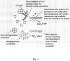
- Intimate coupling of photocatalytic advanced oxidation with microbial activity provides a route to overcoming the limitations of MFC microbial metabolic activity (thereby enhancing energy recovery and COD reduction) and to achieving treatment (oxidation) of hazardous micropollutants.
- the photocatalyst of the present invention may be used in a technique to allow AO and microbial oxidation to occur within the MFC environment, and also to an improved photocatalyst structure for the advanced oxidation stage itself.
- TiO 2 photocatalyst described herein has a very flexible architecture (compliant and reinforced by a titanium wire substrate, for instance), it may be incorporated into a wide range of UV exposure systems and geometries.
- the porous cathode preferably comprises convection channels on which a cathodic catalyst (such as an activated nickel catalyst) is deposited.
- a cathodic catalyst such as an activated nickel catalyst
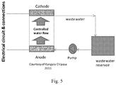
- the fuel cell may comprise an inlet for introducing water into the chamber, an outlet through which treated water can leave the chamber, and means (such as a pump) for feeding water through the inlet, through the anode, through the cathode and out of the outlet. It may additionally comprise an oxygen permeable, water impermeable, layer (such as a PTFE layer) between the cathode and the outside of the cell, whereby oxygen from outside the cell can permeate into the cathode but water cannot escape out of the cell.
- an oxygen permeable, water impermeable, layer such as a PTFE layer
- the preferred embodiment of the present invention the following three features: (i) interconnected micro-pores of porous titanium sponge which provide a low-resistance flow through the anode structure and a cohesive and well-adhered layer of highly porous oxide, including nano-particles of anatase (TiO 2 ) on the surface of the titanium sponge which provide huge surface area that enhances the photo-catalytic oxidation process to extreme efficiency, (ii) a UV transparent porous skeleton (titanium sponge), which is an effective means to introduce the UV energy to the high surface area of TiO 2 thin coatings where the photocatalytic process takes place, and (iii) a metallic substrate which provides mechanical reinforcement to the ceramic photocatalyst surface, allowing it to be flexible and adaptable to a wide range of geometries (for example, it may be wrapped around tubular UV sources, or
- the microorganisms may be in the form of a biofilm attached to or deposited on the anode.
- the micro-porous structure which is a part of the MFC anode protects microbial films from toxic agents, whilst microorganisms rapidly metabolise the available biodegradable substrates releasing protons and electrons. Intimate coupling of AO within the MFC environment provides a route to overcoming the limitations of MFC thereby enhancing energy recovery and removal of biodegradable as well as recalcitrant organics from wastewater.
- Controlling the flow of the feed from the anode to the cathode through the catalyst-coated convection channels (the pores) in the cathode structure enables the transfer of protons to the cathode, thereby enabling oxygen reduction reaction and preventing the back flow of oxygen.
- the convective proton transfer technique enables MFC operation without the application of PEMs thereby overcoming the limitations associated with their use.
- a membraneless, platinum-free, air cathode design in accordance with the present invention preferably utilises a low cost, high performance platinum free oxygen reduction catalyst, bound to a cathode structure exposed to air, incorporating inner and outer PTFE diffusion layers enabling efficient permeation of protons (H + ) and oxygen to the catalyst sites, limiting oxygen permeation into the reactor and preventing water loss from the reactor.
- the membraneless cathode design is achieved via convective proton transfer within the MFC environment.
- the MFC is designed to support continuous flow (convection gradient) from the anode to the cathode, thereby achieving rapid transfer of protons from the anode to the cathode and preventing back-permeation of oxygen into the anode chamber.
- Convective proton transfer techniques has enabled the operation of MFC without a membrane, thereby overcoming the identified limitations associated with internal resistance and pH imbalance and achieving enhanced potential voltage and power generation.
- the anode is made of graphite felt (KFD21002500 - KFD2 FELT) which is commercially available (Gee Graphite Limited, Dewsbury, UK).
- the thickness of the graphite felt is 2 mm and a total length of 2500mm was used.
- the material was cut in 110 mm diameter discs that that were placed vertically in the microbial fuel cell as the anode. A copper wire pushed through the centre of the discs for the electrical connection.
- graphite felt, carbon cloth, knitted carbon cloth and carbon fibre were also tested for this purpose.
- Biofilms on the anode structure were developed by acclimatising a mixture of microorganisms found in activated sludge.
- Activated sludge was obtained from the local wastewater treatment plant (Wanlip Sewage Treatment plant, SevernTrent, UK).
- a solution of synthetic wastewater was used to develop the biofilms (sodium acetate, 1g/L; NH 4 Cl, 310 mg/L; KCl, 130 mg/L; NaH 2 PO 4 , 4.97 g/L; Na 2 HPO 4 , 2.75 g/L; vitamin solution, 12/5 ml/L; mineral water, 12.5 ml/L).
- the described synthetic wastewater as well as real industrial brewery wastewater (Carlsberg, UK) was used.
- the cathode is made of carbon cloth (Scott & Fyfe Ltd, Fife, UK) of 2 mm thickness. The material was cut in discs of 110 mm diameter an impregnated with a catalyst and treated with PTFE to form diffusion layers.
- Photocatalyst of titanium dioxide was grown on titanium wire sponge (Knitmesh Ltd., Holywell, UK) by means of pulsed bi-polar electrolytic discharge oxidation (Keronite International Ltd, Cambridge, UK).
- the diameter of the titanium wire knitted to form a sponge was 0.3 mm.
- the overall thickness of the sponge ranged from 6 mm to 30 mm.
- the oxide layer was produced in thicknesses ranging from 2 ⁇ m to 15 ⁇ m in thickness.
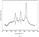
- the resulting photocatalyst was highly flexible, and presented a surface area of over 5000 cm 2 (as verified by BET adsorption - Fig. 14 ), when an oxide layer of ⁇ 5 ⁇ m thickness was applied. It comprised >90 Wt % anatase, as characterised by X-Ray diffraction ( Fig. 15 , 16 ).
- UV lamp assembly Three types of UV sources were assembled and tested: 365 and 385 nm UV-LED lamps (respectively, NC4U133 and NC4U134, Nichia Corporation, Japan) as well as 254 nm UV-mercury lamp (IST, UK).
- 365 and 385 nm UV-LED lamps (respectively, NC4U133 and NC4U134, Nichia Corporation, Japan) as well as 254 nm UV-mercury lamp (IST, UK).
- IST 254 nm UV-mercury lamp
- a peristaltic pump was used (Watson Marlow, 520S).
- the anode was connected externally to the cathode by using a copper wire. Resistors and voltage measurement were achieved by using multimeter computer system (Pico System, Pico Technologies, Cambridge, UK).
- the body of the cell is made of a non-metallic material, delrin (commercially available), which is a highly versatile engineering polymer with high mechanical strength and rigidity and good electrical insulating characteristics.
- a mediator-less MFC In the operation of a mediator-less MFC several factors are limiting steps for electricity generation, such as fuel oxidation at the anode, electron transfer from microorganism to anode, external resistance of the circuit, proton transfer through the membrane to the cathode, and oxygen reduction at the cathode ( Fig. 1 ).
- the acceptability of MFC for wastewater treatment would increase, if use of membrane can be eliminated using some alternative.
- the present invention is the development a membrane-less MFC via convective proton transfer, illustrated in Fig. 1 .
- the MFC is designed to support continuous flow of protons (convection gradient) from the anode to the cathode, thereby achieving rapid transfer of protons from the anode to the cathode and preventing back permeation of oxygen into the anode chamber.
- Convective proton transfer techniques has enabled MFC operation without a membrane, thereby overcoming the identified limitations associated with internal resistance and pH imbalance and achieving enhanced potential voltage and power generation.
- the anode-cathode convection channels ensures establishment of a controlled convection gradient between the anode and cathode compartments and thus efficient transfer of protons to the cathode and prevention of oxygen back-permeation to the anode.
- the membrane-less platinum free air-cathode design is constructed with a low cost, high performance platinum free oxygen reduction catalyst, bound to the cathode structure exposed to air, incorporating inner and outer PTFE diffusion layers enabling efficient permeation of protons and oxygen to the catalyst sites, limiting oxygen permeation into the cell and preventing water loss from the cell.
- Modifications are expected especially as regards to the type and structure of the carbon based anode and cathode materials and the preferred optimum distance between the anode and the cathode, and their preparation including the coating of diffusion layers (PTFE) on the surface of the cathode material.
- PTFE diffusion layers
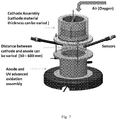
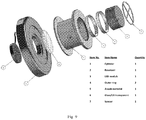
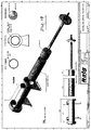
- Figures 8 and 11 show a simple cylindrical element of a titanium dioxide photocatalyst 'sponge' (labelled as item 14 in figure 8 ), exposed from one side (the lower circular face) by an array of UV LEDs (with a UV transparent window and a space between the elements.
- a more demanding arrangement which takes better advantage of the compliance and flexibility of the material to conform to a more common geometry of UV source (i.e. a tube) is shown in Figure 18 .
- Long sheets of mesh may be spirally wound around the tube to form cylinders of photocatalyst material, through which a fluid may be pumped.
- This AdvOxTM unit geometry may be incorporated into the design of a microbial fuel cell.
- a spiral wound section of photocatalyst sponge is created with an outside diameter and internal diameter to suit the dimensions of the UV chamber and the quartz sleeve(s) with an interference fit for better sponge density and location within the unit.
- the chamber and sponge lengths are designed to ensure that the inflow to the unit is not interrupted to improve flow distribution. It is expected that this flow distribution is improved in future designs using CFD and other design tools.
- the UV unit is designed so that the mesh can be easily fitted and removed for maintenance if required.
- a preferred means of achieving the surface oxidation of the porous titanium structure is pulsed electrolytic discharge oxidation, optionally pulsed bi-polar electrolytic discharge oxidation.
- the process known as the Keronite® process is used, with hardware as described in WO9931309 and WO03083181 , and with electrolytes comprising dilute aqueous solutions of phosphates (such as Na 3 PO 4 in concentration ranges from 0.01-0.1M). This exposes a growing anodic oxide to an oxygen-rich plasma at temperatures of over 3000 K for periods of between 1 and 100 microseconds.
Landscapes
- Chemical & Material Sciences (AREA)
- Engineering & Computer Science (AREA)
- Organic Chemistry (AREA)
- Chemical Kinetics & Catalysis (AREA)
- Materials Engineering (AREA)
- Life Sciences & Earth Sciences (AREA)
- Electrochemistry (AREA)
- Water Supply & Treatment (AREA)
- Hydrology & Water Resources (AREA)
- Environmental & Geological Engineering (AREA)
- Health & Medical Sciences (AREA)
- Toxicology (AREA)
- Metallurgy (AREA)
- Physics & Mathematics (AREA)
- Plasma & Fusion (AREA)
- Biochemistry (AREA)
- Microbiology (AREA)
- Manufacturing & Machinery (AREA)
- Sustainable Development (AREA)
- Sustainable Energy (AREA)
- General Chemical & Material Sciences (AREA)
- Catalysts (AREA)
- Treatment Of Water By Oxidation Or Reduction (AREA)
- Fuel Cell (AREA)
- Inert Electrodes (AREA)
Claims (8)
- Verfahren zur Herstellung eines Fotokatalysators, der ein elektrisch leitfähiges Titansubstrat mit einer makroporösen Architektur umfasst, durch Umwandlung exponierter Oberflächen des Titansubstrats in einen mikroporösen Überzug aus Titandioxid mit einer spezifischen Oberfläche von über 5 m2 pro Gramm Oxid durch einen elektrolytischen Plasmaoxidationsprozess; wobei der elektrolytische Plasmaoxidationsprozess ein gepulster, bipolarer elektrolytischer Prozess ist; und wobei der elektrolytische Plasmaoxidationsprozess das Titandioxid während dessen Bildung einem sauerstoffreichen Plasma bei Temperaturen von über 3000 K über Zeiträume von 1 bis 100 Mikrosekunden aussetzt.
- Verfahren nach Anspruch 1, wobei sich das Titandioxid ganz oder teilweise in einer Anatas-Phase befindet.
- Verfahren nach Anspruch 1 oder 2, wobei die makroporöse Architektur aus in einen Schwamm oder ein Gitter gewebten Titandraht gebildet wird.
- Verfahren nach Anspruch 3, wobei der Schwamm oder das Gitter offen oder netzartig ist.
- Verfahren nach Anspruch 1 oder 2, wobei die makroporöse Architektur aus einem perforierten Titanlagenmaterial gebildet wird.
- Verfahren nach einem der Ansprüche 1 bis 5, wobei der elektrolytische Plasmaoxidationsprozess in einem verdünnten, wässrigen, alkalischen Elektrolyt erfolgt.
- Verfahren nach Anspruch 6, wobei der verdünnte, wässrige, alkalische Elektrolyt eine Phosphatlösung ist.
- Verfahren nach einem der Ansprüche 1 bis 7, wobei der Titandioxidüberzug eine niedrige Steifigkeit (E < 50 GPa) aufweist.
Applications Claiming Priority (4)
| Application Number | Priority Date | Filing Date | Title |
|---|---|---|---|
| GBGB1205742.8A GB201205742D0 (en) | 2012-03-30 | 2012-03-30 | Microbial fuel cell |
| GBGB1218832.2A GB201218832D0 (en) | 2012-10-19 | 2012-10-19 | Microbial fuel cell |
| GB1305722.9A GB2505025B (en) | 2012-03-30 | 2013-03-28 | Method for making assembly for photocatalytic treatment of water |
| PCT/GB2013/051444 WO2013144660A2 (en) | 2012-03-30 | 2013-05-30 | Photocatalyst |
Publications (2)
| Publication Number | Publication Date |
|---|---|
| EP2830757A2 EP2830757A2 (de) | 2015-02-04 |
| EP2830757B1 true EP2830757B1 (de) | 2021-01-20 |
Family
ID=48444953
Family Applications (1)
| Application Number | Title | Priority Date | Filing Date |
|---|---|---|---|
| EP13734139.2A Not-in-force EP2830757B1 (de) | 2012-03-30 | 2013-05-30 | Methode zur herstellung eines photokatalysators |
Country Status (4)
| Country | Link |
|---|---|
| US (1) | US9492810B2 (de) |
| EP (1) | EP2830757B1 (de) |
| GB (1) | GB2505025B (de) |
| WO (1) | WO2013144660A2 (de) |
Families Citing this family (18)
| Publication number | Priority date | Publication date | Assignee | Title |
|---|---|---|---|---|
| CN103526251B (zh) * | 2013-10-15 | 2016-08-17 | 北京星航机电装备有限公司 | 一种具有光催化功能的微弧氧化膜层的制备方法 |
| JP6161669B2 (ja) * | 2014-12-26 | 2017-07-12 | ユニ・チャーム株式会社 | 使用済み吸収性物品のリサイクル方法 |
| CN104888746A (zh) * | 2015-06-17 | 2015-09-09 | 湖北工业大学 | 一种高比表面积、高光催化性能二氧化钛纳米带薄膜的制备方法 |
| CN105220202B (zh) * | 2015-10-23 | 2018-03-06 | 北京科技大学 | 一种钛基三维多孔二氧化钛氧化层的制备方法 |
| CN107012494B (zh) * | 2017-03-16 | 2019-04-26 | 东北大学 | 一步法制备以金属或合金为基体的金属氧化物负载纳米催化剂的方法 |
| CN107010714B (zh) * | 2017-05-22 | 2023-04-28 | 东北大学 | 生物电催化与光催化接触氧化耦合的废水处理系统及方法 |
| EP3636429A4 (de) | 2017-06-09 | 2020-05-20 | JFE Steel Corporation | Mehrschichtige struktur und verfahren zur herstellung einer mehrschichtigen struktur |
| US12304844B2 (en) * | 2017-10-25 | 2025-05-20 | Advanced Environmental Technologies, Llc | Method for advanced bioelectrochemical treatment of pollutants |
| RU182587U1 (ru) * | 2018-03-20 | 2018-08-23 | федеральное государственное бюджетное образовательное учреждение высшего образования "Тольяттинский государственный университет" | Установка фотокаталитической очистки воды |
| CA3033255A1 (en) | 2019-02-04 | 2020-08-04 | Rodney HERRING | Photoreactor and formulations for environmental remediation and methods of use thereof |
| CN111167496B (zh) * | 2020-01-09 | 2020-12-25 | 南开大学 | 一种可见光催化材料及其制备方法和应用 |
| CN111762880B (zh) * | 2020-07-22 | 2021-12-10 | 南京理工大学 | 一种基于光激发空穴为电子受体的生物强化处理难降解有机污染物的方法 |
| RU2749814C1 (ru) * | 2020-09-29 | 2021-06-17 | Федеральное государственное бюджетное учреждение науки Институт теплофизики им. С.С. Кутателадзе Сибирского отделения Российской академии наук | СПОСОБ СИНТЕЗА НАНОКОМПОЗИТА Mn-O-C |
| CN112794413B (zh) * | 2020-12-15 | 2022-11-29 | 北京工业大学 | 一种应用于电活化pds体系修饰双金属的石墨毡电极的制备方法及应用 |
| JP7703878B2 (ja) * | 2021-03-31 | 2025-07-08 | 三菱マテリアル株式会社 | チタン基材、水電解用電極、および、固体高分子形水電解装置 |
| CN113354104A (zh) * | 2021-07-01 | 2021-09-07 | 云南华谱量子材料有限公司 | 一种适用于深水环境修复的生态系统及其构建方法 |
| CN114956472B (zh) * | 2022-06-16 | 2023-08-08 | 河海大学 | 一种模块化农村生活污水处理装置 |
| EP4665415A1 (de) | 2023-04-14 | 2025-12-24 | Evoqua Water Technologies Limited | Ultraviolett-generator |
Citations (1)
| Publication number | Priority date | Publication date | Assignee | Title |
|---|---|---|---|---|
| GB2469115A (en) * | 2009-04-03 | 2010-10-06 | Keronite Internat Ltd | Process for the enhanced corrosion protection of valve metals |
Family Cites Families (14)
| Publication number | Priority date | Publication date | Assignee | Title |
|---|---|---|---|---|
| JPH11100695A (ja) * | 1997-09-26 | 1999-04-13 | Nippon Alum Co Ltd | 光触媒活性を有するチタン材の製造方法 |
| JP3370290B2 (ja) * | 1999-03-25 | 2003-01-27 | 剛久 伊藤 | 光触媒材料の製造方法 |
| US6248235B1 (en) * | 1999-03-30 | 2001-06-19 | Robin Scott | Fluid purification system |
| JP2004230301A (ja) * | 2003-01-30 | 2004-08-19 | Noritake Co Ltd | 光触媒体及びその製造方法 |
| NZ544373A (en) * | 2005-12-20 | 2008-05-30 | Auckland Uniservices Ltd | Micro-arc plasma assisted electroless nickel plating methods |
| JP5093801B2 (ja) * | 2007-06-08 | 2012-12-12 | 国立大学法人静岡大学 | 酸化チタン膜成形部材の製造方法、光触媒、光電極、および水処理装置 |
| US8388844B2 (en) * | 2007-08-10 | 2013-03-05 | Arizona Board Of Regents For And On Behalf Of Arizona State University | Intimate coupling of photocatalysis and biodegradation in a photocatalytic circulating-bed biofilm reactor |
| JP5584923B2 (ja) * | 2008-06-27 | 2014-09-10 | 国立大学法人東北大学 | ルチル型二酸化チタン光触媒 |
| US20100047611A1 (en) | 2008-08-25 | 2010-02-25 | Seo-Yong Cho | Nanoporous titanium oxide and method for preparing the same |
| CN101380569B (zh) * | 2008-10-16 | 2010-12-22 | 中国石油大学(华东) | 负载二氧化钛颗粒的三维有序大孔炭制备方法及应用方法 |
| US8975205B2 (en) * | 2008-11-10 | 2015-03-10 | University Of Georgia Research Foundation, Inc. | Photocatalytic structures, methods of making photocatalytic structures, and methods of photocatalysis |
| CN101856609B (zh) * | 2010-06-09 | 2011-11-30 | 桂林电子科技大学 | 海绵钛负载TiO2光催化剂及其制备方法 |
| EP2409954A1 (de) * | 2010-07-20 | 2012-01-25 | National Center for Scientific Research Demokritos | Photokatalytische Reinigungsvorrichtung |
| US20150111725A1 (en) * | 2013-10-21 | 2015-04-23 | Peter C. Van Buskirk | Photocatalytic thin film devices |
-
2013
- 2013-03-28 GB GB1305722.9A patent/GB2505025B/en active Active
- 2013-05-30 US US14/389,284 patent/US9492810B2/en active Active
- 2013-05-30 EP EP13734139.2A patent/EP2830757B1/de not_active Not-in-force
- 2013-05-30 WO PCT/GB2013/051444 patent/WO2013144660A2/en not_active Ceased
Patent Citations (1)
| Publication number | Priority date | Publication date | Assignee | Title |
|---|---|---|---|---|
| GB2469115A (en) * | 2009-04-03 | 2010-10-06 | Keronite Internat Ltd | Process for the enhanced corrosion protection of valve metals |
Also Published As
| Publication number | Publication date |
|---|---|
| GB2505025B (en) | 2019-07-17 |
| WO2013144660A2 (en) | 2013-10-03 |
| US9492810B2 (en) | 2016-11-15 |
| US20150068906A1 (en) | 2015-03-12 |
| WO2013144660A3 (en) | 2013-12-12 |
| EP2830757A2 (de) | 2015-02-04 |
| GB2505025A (en) | 2014-02-19 |
| GB201305722D0 (en) | 2013-05-15 |
Similar Documents
| Publication | Publication Date | Title |
|---|---|---|
| US9492810B2 (en) | Photocatalyst | |
| An et al. | Revealing decay mechanisms of H2O2-based electrochemical advanced oxidation processes after long-term operation for phenol degradation | |
| Jeon et al. | Dual-functional photocatalytic and photoelectrocatalytic systems for energy-and resource-recovering water treatment | |
| Zhao et al. | Superhydrophobic air-breathing cathode for efficient hydrogen peroxide generation through two-electron pathway oxygen reduction reaction | |
| Li et al. | Hydroxyl radical production via a reaction of electrochemically generated hydrogen peroxide and atomic hydrogen: an effective process for contaminant oxidation? | |
| Mathuriya et al. | Architectural adaptations of microbial fuel cells | |
| Xue et al. | Selective electrocatalytic water oxidation to produce H2O2 using a C, N codoped TiO2 electrode in an acidic electrolyte | |
| KR101935075B1 (ko) | 전기화학 전지를 이용하는 효율적인 폐수 처리 | |
| US12545605B2 (en) | “Super-bubble” electro-photo hybrid catalytic system for advanced treatment of organic wastewater | |
| Xie et al. | Maximizing thiophene–sulfur functional groups in carbon catalysts for highly selective H2O2 electrosynthesis | |
| Long et al. | Bioinspired gas manipulation for regulating multiphase interactions in electrochemistry | |
| Liu et al. | Efficient nitrate reduction over novel covalent Ag-salophen polymer-derived “vein-leaf-apple”-like Ag@ carbon structures | |
| Vasconcelos et al. | Recent advances on modified reticulated vitreous carbon for water and wastewater treatment–A mini-review | |
| Liang et al. | Preparation of transition metal composite graphite felt cathode for efficient heterogeneous electro-Fenton process | |
| CN102381753A (zh) | 一种生物电化学膜反应器装置 | |
| Qiu et al. | Review on structural adjustment strategies of titanium‐based metal oxide dimensionally stable anodes in electrochemical advanced oxidation technology | |
| Zhu et al. | Critical review of catalysis-assisted nanofiltration for micropollutants removal: Catalytic coupled nanofiltration system vs catalytic nanofiltration membrane | |
| US20160190627A1 (en) | Filtration-Active Fuel Cell | |
| Chen et al. | Hydroxyl radical and carbonate radical facilitate chlortetracycline degradation in the bio-photoelectrochemical system with a bioanode and a Bi2O3/CuO photocathode using bicarbonate buffer | |
| Chen et al. | Flow-through electrochemical membrane reactor with a self-supported carbon membrane electrode for highly efficient synthesis of hydrogen peroxide | |
| Chaurasiya et al. | Carbon-based electrodes for photo-bio-electrocatalytic microbial fuel and electrolysis cells: advances and perspectives | |
| Wang et al. | Electrocatalytic reduction of nitrate via Co3O4/Ti cathode prepared by electrodeposition paired with IrO2-RuO2 anode | |
| Li et al. | Electrochemical anodic oxidation-based membrane system for micropollutant removal | |
| Thulluru et al. | Sludge-derived hydrochar as a potential electrocatalyst for improved CO 2 reduction in microbial electrosynthesis | |
| Cui et al. | Coaxial dual-tube deviceization of electrode assemblies in paired electrocatalysis for reliable and scalable water remediation |
Legal Events
| Date | Code | Title | Description |
|---|---|---|---|
| PUAI | Public reference made under article 153(3) epc to a published international application that has entered the european phase |
Free format text: ORIGINAL CODE: 0009012 |
|
| 17P | Request for examination filed |
Effective date: 20141008 |
|
| AK | Designated contracting states |
Kind code of ref document: A2 Designated state(s): AL AT BE BG CH CY CZ DE DK EE ES FI FR GB GR HR HU IE IS IT LI LT LU LV MC MK MT NL NO PL PT RO RS SE SI SK SM TR |
|
| AX | Request for extension of the european patent |
Extension state: BA ME |
|
| DAX | Request for extension of the european patent (deleted) | ||
| STAA | Information on the status of an ep patent application or granted ep patent |
Free format text: STATUS: EXAMINATION IS IN PROGRESS |
|
| 17Q | First examination report despatched |
Effective date: 20190412 |
|
| GRAP | Despatch of communication of intention to grant a patent |
Free format text: ORIGINAL CODE: EPIDOSNIGR1 |
|
| STAA | Information on the status of an ep patent application or granted ep patent |
Free format text: STATUS: GRANT OF PATENT IS INTENDED |
|
| INTG | Intention to grant announced |
Effective date: 20200717 |
|
| RIN1 | Information on inventor provided before grant (corrected) |
Inventor name: LEIGH, ANTONY Inventor name: CURRAN, JAMES Inventor name: CHIPASA, KANGALA |
|
| GRAS | Grant fee paid |
Free format text: ORIGINAL CODE: EPIDOSNIGR3 |
|
| GRAA | (expected) grant |
Free format text: ORIGINAL CODE: 0009210 |
|
| STAA | Information on the status of an ep patent application or granted ep patent |
Free format text: STATUS: THE PATENT HAS BEEN GRANTED |
|
| AK | Designated contracting states |
Kind code of ref document: B1 Designated state(s): AL AT BE BG CH CY CZ DE DK EE ES FI FR GB GR HR HU IE IS IT LI LT LU LV MC MK MT NL NO PL PT RO RS SE SI SK SM TR |
|
| REG | Reference to a national code |
Ref country code: GB Ref legal event code: FG4D |
|
| REG | Reference to a national code |
Ref country code: CH Ref legal event code: EP |
|
| REG | Reference to a national code |
Ref country code: DE Ref legal event code: R096 Ref document number: 602013075381 Country of ref document: DE |
|
| REG | Reference to a national code |
Ref country code: AT Ref legal event code: REF Ref document number: 1355900 Country of ref document: AT Kind code of ref document: T Effective date: 20210215 |
|
| REG | Reference to a national code |
Ref country code: IE Ref legal event code: FG4D |
|
| REG | Reference to a national code |
Ref country code: NL Ref legal event code: MP Effective date: 20210120 |
|
| REG | Reference to a national code |
Ref country code: LT Ref legal event code: MG9D |
|
| REG | Reference to a national code |
Ref country code: AT Ref legal event code: MK05 Ref document number: 1355900 Country of ref document: AT Kind code of ref document: T Effective date: 20210120 |
|
| PG25 | Lapsed in a contracting state [announced via postgrant information from national office to epo] |
Ref country code: BG Free format text: LAPSE BECAUSE OF FAILURE TO SUBMIT A TRANSLATION OF THE DESCRIPTION OR TO PAY THE FEE WITHIN THE PRESCRIBED TIME-LIMIT Effective date: 20210420 Ref country code: NL Free format text: LAPSE BECAUSE OF FAILURE TO SUBMIT A TRANSLATION OF THE DESCRIPTION OR TO PAY THE FEE WITHIN THE PRESCRIBED TIME-LIMIT Effective date: 20210120 Ref country code: NO Free format text: LAPSE BECAUSE OF FAILURE TO SUBMIT A TRANSLATION OF THE DESCRIPTION OR TO PAY THE FEE WITHIN THE PRESCRIBED TIME-LIMIT Effective date: 20210420 Ref country code: PT Free format text: LAPSE BECAUSE OF FAILURE TO SUBMIT A TRANSLATION OF THE DESCRIPTION OR TO PAY THE FEE WITHIN THE PRESCRIBED TIME-LIMIT Effective date: 20210520 Ref country code: LT Free format text: LAPSE BECAUSE OF FAILURE TO SUBMIT A TRANSLATION OF THE DESCRIPTION OR TO PAY THE FEE WITHIN THE PRESCRIBED TIME-LIMIT Effective date: 20210120 Ref country code: FI Free format text: LAPSE BECAUSE OF FAILURE TO SUBMIT A TRANSLATION OF THE DESCRIPTION OR TO PAY THE FEE WITHIN THE PRESCRIBED TIME-LIMIT Effective date: 20210120 Ref country code: HR Free format text: LAPSE BECAUSE OF FAILURE TO SUBMIT A TRANSLATION OF THE DESCRIPTION OR TO PAY THE FEE WITHIN THE PRESCRIBED TIME-LIMIT Effective date: 20210120 Ref country code: GR Free format text: LAPSE BECAUSE OF FAILURE TO SUBMIT A TRANSLATION OF THE DESCRIPTION OR TO PAY THE FEE WITHIN THE PRESCRIBED TIME-LIMIT Effective date: 20210421 |
|
| PG25 | Lapsed in a contracting state [announced via postgrant information from national office to epo] |
Ref country code: SE Free format text: LAPSE BECAUSE OF FAILURE TO SUBMIT A TRANSLATION OF THE DESCRIPTION OR TO PAY THE FEE WITHIN THE PRESCRIBED TIME-LIMIT Effective date: 20210120 Ref country code: AT Free format text: LAPSE BECAUSE OF FAILURE TO SUBMIT A TRANSLATION OF THE DESCRIPTION OR TO PAY THE FEE WITHIN THE PRESCRIBED TIME-LIMIT Effective date: 20210120 Ref country code: LV Free format text: LAPSE BECAUSE OF FAILURE TO SUBMIT A TRANSLATION OF THE DESCRIPTION OR TO PAY THE FEE WITHIN THE PRESCRIBED TIME-LIMIT Effective date: 20210120 Ref country code: PL Free format text: LAPSE BECAUSE OF FAILURE TO SUBMIT A TRANSLATION OF THE DESCRIPTION OR TO PAY THE FEE WITHIN THE PRESCRIBED TIME-LIMIT Effective date: 20210120 Ref country code: RS Free format text: LAPSE BECAUSE OF FAILURE TO SUBMIT A TRANSLATION OF THE DESCRIPTION OR TO PAY THE FEE WITHIN THE PRESCRIBED TIME-LIMIT Effective date: 20210120 |
|
| PG25 | Lapsed in a contracting state [announced via postgrant information from national office to epo] |
Ref country code: IS Free format text: LAPSE BECAUSE OF FAILURE TO SUBMIT A TRANSLATION OF THE DESCRIPTION OR TO PAY THE FEE WITHIN THE PRESCRIBED TIME-LIMIT Effective date: 20210520 |
|
| REG | Reference to a national code |
Ref country code: DE Ref legal event code: R097 Ref document number: 602013075381 Country of ref document: DE |
|
| PG25 | Lapsed in a contracting state [announced via postgrant information from national office to epo] |
Ref country code: SM Free format text: LAPSE BECAUSE OF FAILURE TO SUBMIT A TRANSLATION OF THE DESCRIPTION OR TO PAY THE FEE WITHIN THE PRESCRIBED TIME-LIMIT Effective date: 20210120 Ref country code: CZ Free format text: LAPSE BECAUSE OF FAILURE TO SUBMIT A TRANSLATION OF THE DESCRIPTION OR TO PAY THE FEE WITHIN THE PRESCRIBED TIME-LIMIT Effective date: 20210120 Ref country code: EE Free format text: LAPSE BECAUSE OF FAILURE TO SUBMIT A TRANSLATION OF THE DESCRIPTION OR TO PAY THE FEE WITHIN THE PRESCRIBED TIME-LIMIT Effective date: 20210120 |
|
| PLBE | No opposition filed within time limit |
Free format text: ORIGINAL CODE: 0009261 |
|
| STAA | Information on the status of an ep patent application or granted ep patent |
Free format text: STATUS: NO OPPOSITION FILED WITHIN TIME LIMIT |
|
| PG25 | Lapsed in a contracting state [announced via postgrant information from national office to epo] |
Ref country code: DK Free format text: LAPSE BECAUSE OF FAILURE TO SUBMIT A TRANSLATION OF THE DESCRIPTION OR TO PAY THE FEE WITHIN THE PRESCRIBED TIME-LIMIT Effective date: 20210120 Ref country code: ES Free format text: LAPSE BECAUSE OF FAILURE TO SUBMIT A TRANSLATION OF THE DESCRIPTION OR TO PAY THE FEE WITHIN THE PRESCRIBED TIME-LIMIT Effective date: 20210120 Ref country code: SK Free format text: LAPSE BECAUSE OF FAILURE TO SUBMIT A TRANSLATION OF THE DESCRIPTION OR TO PAY THE FEE WITHIN THE PRESCRIBED TIME-LIMIT Effective date: 20210120 Ref country code: RO Free format text: LAPSE BECAUSE OF FAILURE TO SUBMIT A TRANSLATION OF THE DESCRIPTION OR TO PAY THE FEE WITHIN THE PRESCRIBED TIME-LIMIT Effective date: 20210120 |
|
| 26N | No opposition filed |
Effective date: 20211021 |
|
| REG | Reference to a national code |
Ref country code: CH Ref legal event code: PL |
|
| PG25 | Lapsed in a contracting state [announced via postgrant information from national office to epo] |
Ref country code: MC Free format text: LAPSE BECAUSE OF FAILURE TO SUBMIT A TRANSLATION OF THE DESCRIPTION OR TO PAY THE FEE WITHIN THE PRESCRIBED TIME-LIMIT Effective date: 20210120 Ref country code: LU Free format text: LAPSE BECAUSE OF NON-PAYMENT OF DUE FEES Effective date: 20210530 Ref country code: LI Free format text: LAPSE BECAUSE OF NON-PAYMENT OF DUE FEES Effective date: 20210531 Ref country code: CH Free format text: LAPSE BECAUSE OF NON-PAYMENT OF DUE FEES Effective date: 20210531 Ref country code: AL Free format text: LAPSE BECAUSE OF FAILURE TO SUBMIT A TRANSLATION OF THE DESCRIPTION OR TO PAY THE FEE WITHIN THE PRESCRIBED TIME-LIMIT Effective date: 20210120 |
|
| REG | Reference to a national code |
Ref country code: BE Ref legal event code: MM Effective date: 20210531 |
|
| PG25 | Lapsed in a contracting state [announced via postgrant information from national office to epo] |
Ref country code: SI Free format text: LAPSE BECAUSE OF FAILURE TO SUBMIT A TRANSLATION OF THE DESCRIPTION OR TO PAY THE FEE WITHIN THE PRESCRIBED TIME-LIMIT Effective date: 20210120 |
|
| PG25 | Lapsed in a contracting state [announced via postgrant information from national office to epo] |
Ref country code: IT Free format text: LAPSE BECAUSE OF FAILURE TO SUBMIT A TRANSLATION OF THE DESCRIPTION OR TO PAY THE FEE WITHIN THE PRESCRIBED TIME-LIMIT Effective date: 20210120 Ref country code: IE Free format text: LAPSE BECAUSE OF NON-PAYMENT OF DUE FEES Effective date: 20210530 |
|
| PG25 | Lapsed in a contracting state [announced via postgrant information from national office to epo] |
Ref country code: IS Free format text: LAPSE BECAUSE OF FAILURE TO SUBMIT A TRANSLATION OF THE DESCRIPTION OR TO PAY THE FEE WITHIN THE PRESCRIBED TIME-LIMIT Effective date: 20210520 |
|
| PG25 | Lapsed in a contracting state [announced via postgrant information from national office to epo] |
Ref country code: BE Free format text: LAPSE BECAUSE OF NON-PAYMENT OF DUE FEES Effective date: 20210531 |
|
| PG25 | Lapsed in a contracting state [announced via postgrant information from national office to epo] |
Ref country code: HU Free format text: LAPSE BECAUSE OF FAILURE TO SUBMIT A TRANSLATION OF THE DESCRIPTION OR TO PAY THE FEE WITHIN THE PRESCRIBED TIME-LIMIT; INVALID AB INITIO Effective date: 20130530 |
|
| PG25 | Lapsed in a contracting state [announced via postgrant information from national office to epo] |
Ref country code: CY Free format text: LAPSE BECAUSE OF FAILURE TO SUBMIT A TRANSLATION OF THE DESCRIPTION OR TO PAY THE FEE WITHIN THE PRESCRIBED TIME-LIMIT Effective date: 20210120 |
|
| PG25 | Lapsed in a contracting state [announced via postgrant information from national office to epo] |
Ref country code: MK Free format text: LAPSE BECAUSE OF FAILURE TO SUBMIT A TRANSLATION OF THE DESCRIPTION OR TO PAY THE FEE WITHIN THE PRESCRIBED TIME-LIMIT Effective date: 20210120 |
|
| PGFP | Annual fee paid to national office [announced via postgrant information from national office to epo] |
Ref country code: GB Payment date: 20240514 Year of fee payment: 12 |
|
| PGFP | Annual fee paid to national office [announced via postgrant information from national office to epo] |
Ref country code: DE Payment date: 20240515 Year of fee payment: 12 |
|
| PGFP | Annual fee paid to national office [announced via postgrant information from national office to epo] |
Ref country code: FR Payment date: 20240514 Year of fee payment: 12 |
|
| PG25 | Lapsed in a contracting state [announced via postgrant information from national office to epo] |
Ref country code: MT Free format text: LAPSE BECAUSE OF FAILURE TO SUBMIT A TRANSLATION OF THE DESCRIPTION OR TO PAY THE FEE WITHIN THE PRESCRIBED TIME-LIMIT Effective date: 20210120 |
|
| REG | Reference to a national code |
Ref country code: DE Ref legal event code: R119 Ref document number: 602013075381 Country of ref document: DE |
|
| PG25 | Lapsed in a contracting state [announced via postgrant information from national office to epo] |
Ref country code: TR Free format text: LAPSE BECAUSE OF FAILURE TO SUBMIT A TRANSLATION OF THE DESCRIPTION OR TO PAY THE FEE WITHIN THE PRESCRIBED TIME-LIMIT Effective date: 20210120 |
|
| GBPC | Gb: european patent ceased through non-payment of renewal fee |
Effective date: 20250530 |
|
| PG25 | Lapsed in a contracting state [announced via postgrant information from national office to epo] |
Ref country code: GB Free format text: LAPSE BECAUSE OF NON-PAYMENT OF DUE FEES Effective date: 20250530 |
|
| PG25 | Lapsed in a contracting state [announced via postgrant information from national office to epo] |
Ref country code: DE Free format text: LAPSE BECAUSE OF NON-PAYMENT OF DUE FEES Effective date: 20251202 |
|
| PG25 | Lapsed in a contracting state [announced via postgrant information from national office to epo] |
Ref country code: FR Free format text: LAPSE BECAUSE OF NON-PAYMENT OF DUE FEES Effective date: 20250531 |