EP2830063A1 - Appareil, procédé et programme d'ordinateur permettant de décoder un signal audio codé - Google Patents
Appareil, procédé et programme d'ordinateur permettant de décoder un signal audio codé Download PDFInfo
- Publication number
- EP2830063A1 EP2830063A1 EP13189382.8A EP13189382A EP2830063A1 EP 2830063 A1 EP2830063 A1 EP 2830063A1 EP 13189382 A EP13189382 A EP 13189382A EP 2830063 A1 EP2830063 A1 EP 2830063A1
- Authority
- EP
- European Patent Office
- Prior art keywords
- frequency
- spectral
- signal
- portions
- tile
- Prior art date
- Legal status (The legal status is an assumption and is not a legal conclusion. Google has not performed a legal analysis and makes no representation as to the accuracy of the status listed.)
- Withdrawn
Links
Images


Classifications
-
- G—PHYSICS
- G10—MUSICAL INSTRUMENTS; ACOUSTICS
- G10L—SPEECH ANALYSIS OR SYNTHESIS; SPEECH RECOGNITION; SPEECH OR VOICE PROCESSING; SPEECH OR AUDIO CODING OR DECODING
- G10L21/00—Processing of the speech or voice signal to produce another audible or non-audible signal, e.g. visual or tactile, in order to modify its quality or its intelligibility
- G10L21/02—Speech enhancement, e.g. noise reduction or echo cancellation
- G10L21/038—Speech enhancement, e.g. noise reduction or echo cancellation using band spreading techniques
- G10L21/0388—Details of processing therefor
-
- G—PHYSICS
- G10—MUSICAL INSTRUMENTS; ACOUSTICS
- G10L—SPEECH ANALYSIS OR SYNTHESIS; SPEECH RECOGNITION; SPEECH OR VOICE PROCESSING; SPEECH OR AUDIO CODING OR DECODING
- G10L19/00—Speech or audio signals analysis-synthesis techniques for redundancy reduction, e.g. in vocoders; Coding or decoding of speech or audio signals, using source filter models or psychoacoustic analysis
- G10L19/008—Multichannel audio signal coding or decoding using interchannel correlation to reduce redundancy, e.g. joint-stereo, intensity-coding or matrixing
-
- G—PHYSICS
- G10—MUSICAL INSTRUMENTS; ACOUSTICS
- G10L—SPEECH ANALYSIS OR SYNTHESIS; SPEECH RECOGNITION; SPEECH OR VOICE PROCESSING; SPEECH OR AUDIO CODING OR DECODING
- G10L19/00—Speech or audio signals analysis-synthesis techniques for redundancy reduction, e.g. in vocoders; Coding or decoding of speech or audio signals, using source filter models or psychoacoustic analysis
- G10L19/02—Speech or audio signals analysis-synthesis techniques for redundancy reduction, e.g. in vocoders; Coding or decoding of speech or audio signals, using source filter models or psychoacoustic analysis using spectral analysis, e.g. transform vocoders or subband vocoders
- G10L19/0204—Speech or audio signals analysis-synthesis techniques for redundancy reduction, e.g. in vocoders; Coding or decoding of speech or audio signals, using source filter models or psychoacoustic analysis using spectral analysis, e.g. transform vocoders or subband vocoders using subband decomposition
-
- G—PHYSICS
- G10—MUSICAL INSTRUMENTS; ACOUSTICS
- G10L—SPEECH ANALYSIS OR SYNTHESIS; SPEECH RECOGNITION; SPEECH OR VOICE PROCESSING; SPEECH OR AUDIO CODING OR DECODING
- G10L19/00—Speech or audio signals analysis-synthesis techniques for redundancy reduction, e.g. in vocoders; Coding or decoding of speech or audio signals, using source filter models or psychoacoustic analysis
- G10L19/02—Speech or audio signals analysis-synthesis techniques for redundancy reduction, e.g. in vocoders; Coding or decoding of speech or audio signals, using source filter models or psychoacoustic analysis using spectral analysis, e.g. transform vocoders or subband vocoders
- G10L19/0212—Speech or audio signals analysis-synthesis techniques for redundancy reduction, e.g. in vocoders; Coding or decoding of speech or audio signals, using source filter models or psychoacoustic analysis using spectral analysis, e.g. transform vocoders or subband vocoders using orthogonal transformation
-
- G—PHYSICS
- G10—MUSICAL INSTRUMENTS; ACOUSTICS
- G10L—SPEECH ANALYSIS OR SYNTHESIS; SPEECH RECOGNITION; SPEECH OR VOICE PROCESSING; SPEECH OR AUDIO CODING OR DECODING
- G10L19/00—Speech or audio signals analysis-synthesis techniques for redundancy reduction, e.g. in vocoders; Coding or decoding of speech or audio signals, using source filter models or psychoacoustic analysis
- G10L19/02—Speech or audio signals analysis-synthesis techniques for redundancy reduction, e.g. in vocoders; Coding or decoding of speech or audio signals, using source filter models or psychoacoustic analysis using spectral analysis, e.g. transform vocoders or subband vocoders
- G10L19/022—Blocking, i.e. grouping of samples in time; Choice of analysis windows; Overlap factoring
- G10L19/025—Detection of transients or attacks for time/frequency resolution switching
-
- G—PHYSICS
- G10—MUSICAL INSTRUMENTS; ACOUSTICS
- G10L—SPEECH ANALYSIS OR SYNTHESIS; SPEECH RECOGNITION; SPEECH OR VOICE PROCESSING; SPEECH OR AUDIO CODING OR DECODING
- G10L19/00—Speech or audio signals analysis-synthesis techniques for redundancy reduction, e.g. in vocoders; Coding or decoding of speech or audio signals, using source filter models or psychoacoustic analysis
- G10L19/02—Speech or audio signals analysis-synthesis techniques for redundancy reduction, e.g. in vocoders; Coding or decoding of speech or audio signals, using source filter models or psychoacoustic analysis using spectral analysis, e.g. transform vocoders or subband vocoders
- G10L19/028—Noise substitution, i.e. substituting non-tonal spectral components by noisy source
-
- G—PHYSICS
- G10—MUSICAL INSTRUMENTS; ACOUSTICS
- G10L—SPEECH ANALYSIS OR SYNTHESIS; SPEECH RECOGNITION; SPEECH OR VOICE PROCESSING; SPEECH OR AUDIO CODING OR DECODING
- G10L19/00—Speech or audio signals analysis-synthesis techniques for redundancy reduction, e.g. in vocoders; Coding or decoding of speech or audio signals, using source filter models or psychoacoustic analysis
- G10L19/02—Speech or audio signals analysis-synthesis techniques for redundancy reduction, e.g. in vocoders; Coding or decoding of speech or audio signals, using source filter models or psychoacoustic analysis using spectral analysis, e.g. transform vocoders or subband vocoders
- G10L19/03—Spectral prediction for preventing pre-echo; Temporary noise shaping [TNS], e.g. in MPEG2 or MPEG4
-
- G—PHYSICS
- G10—MUSICAL INSTRUMENTS; ACOUSTICS
- G10L—SPEECH ANALYSIS OR SYNTHESIS; SPEECH RECOGNITION; SPEECH OR VOICE PROCESSING; SPEECH OR AUDIO CODING OR DECODING
- G10L19/00—Speech or audio signals analysis-synthesis techniques for redundancy reduction, e.g. in vocoders; Coding or decoding of speech or audio signals, using source filter models or psychoacoustic analysis
- G10L19/02—Speech or audio signals analysis-synthesis techniques for redundancy reduction, e.g. in vocoders; Coding or decoding of speech or audio signals, using source filter models or psychoacoustic analysis using spectral analysis, e.g. transform vocoders or subband vocoders
- G10L19/032—Quantisation or dequantisation of spectral components
-
- G—PHYSICS
- G10—MUSICAL INSTRUMENTS; ACOUSTICS
- G10L—SPEECH ANALYSIS OR SYNTHESIS; SPEECH RECOGNITION; SPEECH OR VOICE PROCESSING; SPEECH OR AUDIO CODING OR DECODING
- G10L19/00—Speech or audio signals analysis-synthesis techniques for redundancy reduction, e.g. in vocoders; Coding or decoding of speech or audio signals, using source filter models or psychoacoustic analysis
- G10L19/04—Speech or audio signals analysis-synthesis techniques for redundancy reduction, e.g. in vocoders; Coding or decoding of speech or audio signals, using source filter models or psychoacoustic analysis using predictive techniques
- G10L19/06—Determination or coding of the spectral characteristics, e.g. of the short-term prediction coefficients
-
- G—PHYSICS
- G10—MUSICAL INSTRUMENTS; ACOUSTICS
- G10L—SPEECH ANALYSIS OR SYNTHESIS; SPEECH RECOGNITION; SPEECH OR VOICE PROCESSING; SPEECH OR AUDIO CODING OR DECODING
- G10L19/00—Speech or audio signals analysis-synthesis techniques for redundancy reduction, e.g. in vocoders; Coding or decoding of speech or audio signals, using source filter models or psychoacoustic analysis
- G10L19/04—Speech or audio signals analysis-synthesis techniques for redundancy reduction, e.g. in vocoders; Coding or decoding of speech or audio signals, using source filter models or psychoacoustic analysis using predictive techniques
- G10L19/16—Vocoder architecture
- G10L19/18—Vocoders using multiple modes
-
- G—PHYSICS
- G10—MUSICAL INSTRUMENTS; ACOUSTICS
- G10L—SPEECH ANALYSIS OR SYNTHESIS; SPEECH RECOGNITION; SPEECH OR VOICE PROCESSING; SPEECH OR AUDIO CODING OR DECODING
- G10L21/00—Processing of the speech or voice signal to produce another audible or non-audible signal, e.g. visual or tactile, in order to modify its quality or its intelligibility
- G10L21/02—Speech enhancement, e.g. noise reduction or echo cancellation
- G10L21/038—Speech enhancement, e.g. noise reduction or echo cancellation using band spreading techniques
-
- G—PHYSICS
- G10—MUSICAL INSTRUMENTS; ACOUSTICS
- G10L—SPEECH ANALYSIS OR SYNTHESIS; SPEECH RECOGNITION; SPEECH OR VOICE PROCESSING; SPEECH OR AUDIO CODING OR DECODING
- G10L25/00—Speech or voice analysis techniques not restricted to a single one of groups G10L15/00 - G10L21/00
- G10L25/03—Speech or voice analysis techniques not restricted to a single one of groups G10L15/00 - G10L21/00 characterised by the type of extracted parameters
- G10L25/06—Speech or voice analysis techniques not restricted to a single one of groups G10L15/00 - G10L21/00 characterised by the type of extracted parameters the extracted parameters being correlation coefficients
-
- G—PHYSICS
- G10—MUSICAL INSTRUMENTS; ACOUSTICS
- G10L—SPEECH ANALYSIS OR SYNTHESIS; SPEECH RECOGNITION; SPEECH OR VOICE PROCESSING; SPEECH OR AUDIO CODING OR DECODING
- G10L25/00—Speech or voice analysis techniques not restricted to a single one of groups G10L15/00 - G10L21/00
- G10L25/03—Speech or voice analysis techniques not restricted to a single one of groups G10L15/00 - G10L21/00 characterised by the type of extracted parameters
- G10L25/18—Speech or voice analysis techniques not restricted to a single one of groups G10L15/00 - G10L21/00 characterised by the type of extracted parameters the extracted parameters being spectral information of each sub-band
-
- G—PHYSICS
- G10—MUSICAL INSTRUMENTS; ACOUSTICS
- G10L—SPEECH ANALYSIS OR SYNTHESIS; SPEECH RECOGNITION; SPEECH OR VOICE PROCESSING; SPEECH OR AUDIO CODING OR DECODING
- G10L25/00—Speech or voice analysis techniques not restricted to a single one of groups G10L15/00 - G10L21/00
- G10L25/03—Speech or voice analysis techniques not restricted to a single one of groups G10L15/00 - G10L21/00 characterised by the type of extracted parameters
- G10L25/21—Speech or voice analysis techniques not restricted to a single one of groups G10L15/00 - G10L21/00 characterised by the type of extracted parameters the extracted parameters being power information
-
- H—ELECTRICITY
- H03—ELECTRONIC CIRCUITRY
- H03M—CODING; DECODING; CODE CONVERSION IN GENERAL
- H03M7/00—Conversion of a code where information is represented by a given sequence or number of digits to a code where the same, similar or subset of information is represented by a different sequence or number of digits
- H03M7/30—Compression; Expansion; Suppression of unnecessary data, e.g. redundancy reduction
-
- G—PHYSICS
- G10—MUSICAL INSTRUMENTS; ACOUSTICS
- G10L—SPEECH ANALYSIS OR SYNTHESIS; SPEECH RECOGNITION; SPEECH OR VOICE PROCESSING; SPEECH OR AUDIO CODING OR DECODING
- G10L19/00—Speech or audio signals analysis-synthesis techniques for redundancy reduction, e.g. in vocoders; Coding or decoding of speech or audio signals, using source filter models or psychoacoustic analysis
- G10L19/02—Speech or audio signals analysis-synthesis techniques for redundancy reduction, e.g. in vocoders; Coding or decoding of speech or audio signals, using source filter models or psychoacoustic analysis using spectral analysis, e.g. transform vocoders or subband vocoders
- G10L19/0204—Speech or audio signals analysis-synthesis techniques for redundancy reduction, e.g. in vocoders; Coding or decoding of speech or audio signals, using source filter models or psychoacoustic analysis using spectral analysis, e.g. transform vocoders or subband vocoders using subband decomposition
- G10L19/0208—Subband vocoders
-
- H—ELECTRICITY
- H04—ELECTRIC COMMUNICATION TECHNIQUE
- H04S—STEREOPHONIC SYSTEMS
- H04S1/00—Two-channel systems
- H04S1/007—Two-channel systems in which the audio signals are in digital form
Definitions
- the present invention relates to audio coding/decoding and, particularly, to audio coding using Intelligent Gap Filling (IGF).
- IGF Intelligent Gap Filling
- Audio coding is the domain of signal compression that deals with exploiting redundancy and irrelevancy in audio signals using psychoacoustic knowledge.
- Today audio codecs typically need around 60 kbps/channel for perceptually transparent coding of almost any type of audio signal.
- Newer codecs are aimed at reducing the coding bitrate by exploiting spectral similarities in the signal using techniques such as bandwidth extension (BWE).
- BWE bandwidth extension
- a BWE scheme uses a low bitrate parameter set to represent the high frequency (HF) components of an audio signal.
- the HF spectrum is filled up with spectral content from low frequency (LF) regions and the spectral shape, tilt and temporal continuity adjusted to maintain the timbre and color of the original signal.
- LF low frequency
- Such BWE methods enable audio codecs to retain good quality at even low bitrates of around 24 kbps/channel.
- the inventive audio coding system efficiently codes arbitrary audio signals at a wide range of bitrates. Whereas, for high bitrates, the inventive system converges to transparency, for low bitrates perceptual annoyance is minimized. Therefore, the main share of available bitrate is used to waveform code just the perceptually most relevant structure of the signal in the encoder, and the resulting spectral gaps are filled in the decoder with signal content that roughly approximates the original spectrum. A very limited bit budget is consumed to control the parameter driven so-called spectral Intelligent Gap Filling (IGF) by dedicated side information transmitted from the encoder to the decoder.
- IGF spectral Intelligent Gap Filling
- PPS Perceptual Noise Substitution
- AAC MPEG-4 Advanced Audio Coding
- a further provision that also enables extended audio bandwidth at low bitrates is the noise filling technique contained in MPEG-D Unified Speech and Audio Coding (USAC) [7]. Spectral gaps (zeroes) that are inferred by the dead-zone of the quantizer due to a too coarse quantization, are subsequently filled with artificial noise in the decoder and scaled by a parameter-driven post-processing.
- USAC MPEG-D Unified Speech and Audio Coding
- ASR Accurate Spectral Replacement
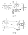
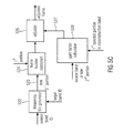
- Fig. 13a illustrates a schematic diagram of an audio encoder for a bandwidth extension technology as, for example, used in High Efficiency Advanced Audio Coding (HE-AAC).
- An audio signal at line 1300 is input into a filter system comprising of a low pass 1302 and a high pass 1304.
- the signal output by the high pass filter 1304 is input into a parameter extractor/coder 1306.
- the parameter extractor/coder 1306 is configured for calculating and coding parameters such as a spectral envelope parameter, a noise addition parameter, a missing harmonics parameter, or an inverse filtering parameter, for example. These extracted parameters are input into a bit stream multiplexer 1308.
- the low pass output signal is input into a processor typically comprising the functionality of a down sampler 1310 and a core coder 1312.
- the low pass 1302 restricts the bandwidth to be encoded to a significantly smaller bandwidth than occurring in the original input audio signal on line 1300. This provides a significant coding gain due to the fact that the whole functionalities occurring in the core coder only have to operate on a signal with a reduced bandwidth.
- the bandwidth of the audio signal on line 1300 is 20 kHz and when the low pass filter 1302 exemplarily has a bandwidth of 4 kHz, in order to fulfill the sampling theorem, it is theoretically sufficient that the signal subsequent to the down sampler has a sampling frequency of 8 kHz, which is a substantial reduction to the sampling rate required for the audio signal 1300 which has to be at least 40 kHz.
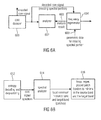
- Fig. 13b illustrates a schematic diagram of a corresponding bandwidth extension decoder.
- the decoder comprises a bitstream multiplexer 1320.
- the bitstream demultiplexer 1320 extracts an input signal for a core decoder 1322 and an input signal for a parameter decoder 1324.
- a core decoder output signal has, in the above example, a sampling rate of 8 kHz and, therefore, a bandwidth of 4 kHz while, for a complete bandwidth reconstruction, the output signal of a high frequency reconstructor 1330 must be at 20 kHz requiring a sampling rate of at least 40 kHz.
- a decoder processor having the functionality of an upsampler 1325 and a filterbank 1326 is required.
- the high frequency reconstructor 1330 then receives the frequency-analyzed low frequency signal output by the filterbank 1326 and reconstructs the frequency range defined by the high pass filter 1304 of Fig. 13a using the parametric representation of the high frequency band.
- the high frequency reconstructor 1330 has several functionalities such as the regeneration of the upper frequency range using the source range in the low frequency range, a spectral envelope adjustment, a noise addition functionality and a functionality to introduce missing harmonics in the upper frequency range and, if applied and calculated in the encoder of Fig. 13a , an inverse filtering operation in order to account for the fact that the higher frequency range is typically not as tonal as the lower frequency range.
- missing harmonics are re-synthesized on the decoder-side and are placed exactly in the middle of a reconstruction band.
- all missing harmonic lines that have been determined in a certain reconstruction band are not placed at the frequency values where they were located in the original signal. Instead, those missing harmonic lines are placed at frequencies in the center of the certain band.
- the error in frequency introduced by placing this missing harmonics line in the reconstructed signal at the center of the band is close to 50% of the individual reconstruction band, for which parameters have been generated and transmitted.
- the core decoder nevertheless generates a time domain signal which is then, again, converted into a spectral domain by the filter bank 1326 functionality.
- This introduces additional processing delays, may introduce artifacts due to tandem processing of firstly transforming from the spectral domain into the frequency domain and again transforming into typically a different frequency domain and, of course, this also requires a substantial amount of computation complexity and thereby electric power, which is specifically an issue when the bandwidth extension technology is applied in mobile devices such as mobile phones, tablet or laptop computers, etc.
- the reconstruction of the HF spectral region above a given so-called cross-over frequency is often based on spectral patching.
- Other schemes that are functional to fill spectral gaps e.g. Intelligent Gap Filling (IGF)
- IGF Intelligent Gap Filling
- the HF region is composed of multiple adjacent patches or tiles and each of these patches or tiles is sourced from band-pass (BP) regions of the LF spectrum below the given cross-over frequency.
- BP band-pass
- State-of-the-art systems efficiently perform the patching or tiling within a filterbank representation by copying a set of adjacent subband coefficients from a source to the target region.
- the assemblage of the reconstructed signal from the LF band and adjacent patches within the HF band can lead to beating, dissonance and auditory roughness.
- the proposed solution in [19] has some drawbacks: First, the strict replacement of spectral content by either zeros or noise can also impair the perceptual quality of the signal. Moreover, the proposed processing is not signal adaptive and can therefore harm perceptual quality in some cases. For example, if the signal contains transients, this can lead to pre- and post-echoes.
- dissonances can also occur at transitions between consecutive HF patches.
- the proposed solution in [19] is only functional to remedy dissonances that occur at cross-over frequency between LF and BWE-regenerated HF.
- BWE systems can also be realized in transform based implementations, like e.g. the Modified Discrete Cosine Transform (MDCT). Transforms like MDCT are very prone to so-called warbling [20] or ringing artifacts that occur if bandpass regions of spectral coefficients are copied or spectral coefficients are set to zero like proposed in [19].
- MDCT Modified Discrete Cosine Transform
- US Patent 8,412,365 discloses to use, in filterbank based translation or folding, so-called guard-bands which are inserted and made of one or several subband channels set to zero.
- a number of filterbank channels is used as guard-bands, and a bandwidth of a guard-band should be 0,5 Bark.
- These dissonance guard-bands are partially reconstructed using random white noise signals, i.e., the subbands are fed with white noise instead of being zero.
- the guard bands are inserted irrespective of the current signal to processed.
- a decoder-side signal analysis using an analyzer is performed for analyzing the decoded core signal before or after performing a frequency regeneration operation to provide an analysis result. Then, this analysis result is used by a frequency regenerator for regenerating spectral portions not included in the decoded core signal.
- a signal-dependent patching or tiling is performed, in which, for example, the core signal can be analyzed to find local minima in the core signal and, then, the core range is selected so that the frequency borders of the core range coincide with local minima in the core signal spectrum.
- a signal analysis can be performed on a preliminary regenerated signal or preliminary frequency-patched or tiled signal, wherein, after the preliminary frequency regeneration procedure, the border between the core range and the reconstruction range is analyzed in order to detect any artifact-creating signal portions such as tonal portions being problematic in that they are quite close to each other to generate a beating artifact when being reconstructed.
- the borders can also be examined in such a way that a halfway-clipping of a tonal portion is detected and this clipping of a tonal portion would also create an artifact when being reconstructed as it is.
- the frequency border of the reconstruction range and/or the source range and/or between two individual frequency tiles or patches in the reconstruction range can be modified by a signal manipulator in order to again perform a reconstruction with the newly set borders.
- the frequency regeneration is a regeneration based on the analysis result in that the frequency borders are left as they are and an elimination or at least attenuation of problematic tonal portions near the frequency borders between the source range and the reconstruction range or between two individual frequency tiles or patches within the reconstruction range is done.
- problematic tonal portions can be close tones that would result in a beating artifact or could be halfway-clipped tonal portions.
- a single tone does not directly map to a single spectral line. Instead, a single tone will map to a group of spectral lines with certain amplitudes depending on the phase of the tone.
- a patching operation clips this tonal portion, then this will result in an artifact after reconstruction even though a perfect reconstruction is applied as in an MDCT reconstructor. This is due to the fact that the MDCT reconstructor would require the complete tonal pattern for a tone in order to finally correctly reconstruct this tone. Due to the fact that a clipping has taken place before, this is not possible anymore and, therefore, a time varying warbling artifact will be created.
- the frequency regenerator will avoid this situation by attenuating the complete tonal portion creating an artifact or as discussed before, by changing corresponding border frequencies or by applying both measures or by even reconstructing the clipped portion based on a certain pre-knowledge on such tonal patterns.
- a cross-over filtering can be applied for spectrally cross-over filtering the decoded core signal and the first frequency tile having frequencies extending from a gap filling frequency to a first tile stop frequency or for a spectrally cross-over filtering a first frequency tile and a second frequency tile.
- This cross-over filtering is useful for reducing the so-called filter ringing.
- the inventive approach is mainly intended to be applied within a BWE based on a transform like the MDCT. Nevertheless, the teachings of the invention are generally applicable, e.g. analogously within a Quadrature Mirror Filter bank (QMF) based system, especially if the system is critically sampled, e.g. a real-valued QMF representation.
- QMF Quadrature Mirror Filter bank
- the inventive approach is based on the observation that auditory roughness, beatings and dissonance can only take place if the signal content in spectral regions closed to transition points (like the cross-over frequency or patch borders) is very tonal. Therefore, the proposed solution for the drawbacks found in state of the art consists of a signal adaptive detection of tonal components in transition regions and the subsequent attenuation or removal of these components.
- the attenuation or removal of these components can be preferably accomplished by spectral interpolation from foot to foot of such a component, or, alternatively by zero or noise insertion.
- the spectral location of the transitions can be chosen signal adaptively such that transition artifacts are minimized.
- this technique can be used to reduce or even avoid filter ringing.
- ringing is an audible and annoying artifact.
- Filter ringing artifacts are caused by the so-called brick-wall characteristic of a filter in the transition band (a steep transition from pass band to stop band at the cut-off frequency).
- Such filters can be efficiently implemented by setting one coefficient or groups of coefficients to zero in the frequency domain of a time-frequency transform. So, in the case of BWE, we propose to apply a cross-over filter at each transition frequency between patches or between core-band and first patch to reduce said ringing effect.
- the cross-over filter can be implemented by spectral weighting in the transform domain employing suitable gain functions.
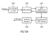
- an apparatus for decoding an encoded audio signal comprises a core decoder, a tile generator for generating one or more spectral tiles having frequencies not included in the decoded core signal using a spectral portion of the decoded core signal and a cross-over filter for spectrally cross-over filtering the decoded core signal and a first frequency tile having frequencies extending from a gap filling frequency to a first tile stop frequency or for spectrally cross-over filtering a tile and a further frequency tile, the further frequency tile having a lower border frequency being frequency-adjacent to an upper border frequency of the frequency tile.
- this procedure is intended to be applied within a bandwidth extension based on a transform like the MDCT.
- the present invention is generally applicable and, particularly in a bandwidth extension scenario relying on a quadrature mirror filterbank (QMF), particularly if the system is critically sampled, for example when there is a real-valued QMF representation as a time-frequency conversion or as a frequency-time conversion.
- QMF quadrature mirror filterbank
- the embodiment is particularly useful for transient-like signals, since for such transient-like signals, ringing is an audible and annoying artifact.
- Filter ringing artifacts are caused by the so-called brick-wall characteristic of a filter in the transition band, i.e., a steep transition from a pass band to a stop band at a cut-off frequency.
- Such filters can be efficiently implemented by setting one coefficient or groups of coefficients to zero in a frequency domain of a time- frequency transform. Therefore, the present invention relies on a cross-over filter at each transition frequency between patches/tiles or between a core band and a first patch/tile to reduce this ringing artifact.
- the cross-over filter is preferably implemented by spectral weighting in the transform domain employing suitable gain functions.
- the cross-over filter is signal-adaptive and consists of two filters, a fade-out filter, which is applied to the lower spectral region and a fade-in filter, which is applied to the higher spectral region.
- the filters can be symmetric or asymmetric depending on the specific implementation.
- a frequency tile or frequency patch is not only subjected to cross-over filtering, but the tile generator preferably performs, before performing the cross-over filtering, a patch adaption comprising a setting of frequency borders at spectral minima and a removal or attenuation of tonal portions remaining in transition ranges around the transition frequencies.
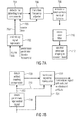
- Fig. 6a illustrates an apparatus for decoding an encoded audio signal comprising an encoded core signal and parametric data.
- the apparatus comprises a core decoder 600 for decoding the encoded core signal to obtain a decoded core signal, an analyzer 602 for analyzing the decoded core signal before or after performing a frequency regeneration operation.
- the analyzer 602 is configured for providing an analysis result 603.
- the frequency regenerator 604 is configured for regenerating spectral portions not included in the decoded core signal using a spectral portion of the decoded core signal, envelope data 605 for the missing spectral portions and the analysis result 603.
- the frequency regeneration is not performed on the decoder-side signal-independent, but is performed signal-dependent.
- the core decoder 600 is implemented as an entropy (e.g. Huffman or arithmetic decoder) decoding and dequantizing stage 612 as illustrated in Fig. 6b .
- the core decoder 600 then outputs a core signal spectrum and the spectrum is analyzed by the spectral analyzer 614 which is, quite similar to the analyzer 602 in Fig. 6a .
- the spectral analyzer is configured for analyzing the spectral signal so that local minima in the source band and/or in a target band, i.e., in the frequency patches or frequency tiles are determined. Then, the frequency regenerator 604 performs, as illustrated at 616, a frequency regeneration where the patch borders are placed to minima in the source band and/or the target band.
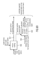
- a preliminary signal regenerator 702 receives, as an input, source data from the source band and, additionally, preliminary patch information such as preliminary border frequencies. Then, a preliminary regenerated signal 703 is generated, which is detected by the detector 704 for detecting the tonal components within the preliminary reconstructed signal 703. Alternatively or additionally, the source data 705 can also be analyzed by the detector corresponding to the analyzer 602 of Fig. 6a . Then, the preliminary signal regeneration step would not be necessary.
- the minima or tonal portions can be detected even by considering only the source data, whether there are tonal portions close to the upper border of the core range or at a frequency border between two individually generated frequency tiles as will be discussed later with respect to Fig. 12b .
- a transition frequency adjuster 706 performs an adjustment of a transition frequency such as a transition frequency or cross-over frequency or gap filling start frequency between the core band and the reconstruction band or between individual frequency portions generated by one and the same source data in the reconstruction band.
- the output signal of block 706 is forwarded to a remover 708 of tonal components at borders.
- the remover is configured for removing remaining tonal components which are still there subsequent to the transition frequency adjustment by block 706.
- the result of the remover 708 is then forwarded to a cross-over filter 710 in order to address the filter ringing problem and the result of the cross-over filter 710 is then input into a spectral envelope shaping block 712 which performs a spectral envelope shaping in the reconstruction band.
- the detection of tonal components in block 704 can be both performed on a source data 705 or a preliminary reconstructed signal 703. This embodiment is illustrated in Fig. 7b , where a preliminary regenerated signal is created as shown in block 718.
- the signal corresponding to signal 703 of Fig. 7a is then forwarded to a detector 720 which detects artifact-creating components.
- the detector 720 can be configured for being a detector for detecting tonal components at frequency borders as illustrated at 704 in Fig. 7a
- the detector can also be implemented to detect other artifact-creating components.
- Such spectral components can be even other components than tonal components and a detection whether an artifact has been created can be performed by trying different regenerations and comparing the different regeneration results in order to find out which one has provided artifact-creating components.
- the detector 720 now controls a manipulator 722 for manipulating the signal, i.e., the preliminary regenerated signal.
- This manipulation can be done by actually processing the preliminary regenerated signal by line 723 or by newly performing a regeneration, but now with, for example, the amended transition frequencies as illustrated by line 724.
- One implementation of the manipulation procedure is that the transition frequency is adjusted as illustrated at 706 in Fig. 7a .
- a further implementation is illustrated in Fig. 8a , which can be performed instead of block 706 or together with block 706 of Fig. 7a .
- a detector 802 is provided for detecting start and end frequencies of a problematic tonal portion.
- an interpolator 804 is configured for interpolating and, preferably complex interpolating between the start and the end of the tonal portion within the spectral range.
- the tonal portion is replaced by the interpolation result.
- Fig. 8a An alternative implementation is illustrated in Fig. 8a by blocks 808, 810. Instead of performing an interpolation, a random generation of spectral lines 808 is performed between the start and the end of the tonal portion. Then, an energy adjustment of the randomly generated spectral lines is performed as illustrated at 810, and the energy of the randomly generated spectral lines is set so that the energy is similar to the adjacent non-tonal spectral parts. Then, the tonal portion is replaced by envelope-adjusted randomly generated spectral lines.
- the spectral lines can be randomly generated or pseudo randomly generated in order to provide a replacement signal which is, as far as possible, artifact-free.
- a frequency tile generator located within the frequency regenerator 604 of Fig. 6a is illustrated at block 820.
- the frequency tile generator uses predetermined frequency borders.
- the analyzer analyzes the signal generated by the frequency tile generator, and the frequency tile generator 820 is preferably configured for performing multiple tiling operations to generate multiple frequency tiles.
- the manipulator 824 in Fig. 8b manipulates the result of the frequency tile generator in accordance with the analysis result output by the analyzer 822.
- the manipulation can be the change of frequency borders or the attenuation of individual portions.
- a spectral envelope adjuster 826 performs a spectral envelope adjustment using the parametric information 605 as already discussed in the context of Fig. 6a .
- the spectrally adjusted signal output by block 826 is input into a frequency-time converter which, additionally, receives the first spectral portions, i.e., a spectral representation of the output signal of the core decoder 600.
- the output of the frequency-time converter 828 can then be used for storage or for transmitting to a loudspeaker for audio rendering.
- the present invention can be applied either to known frequency regeneration procedures such as illustrated in Figs. 13a, 13b or can preferably be applied within the intelligent gap filling context, which is subsequently described with respect to Figs. 1 a to 5b and 9a to 10d.
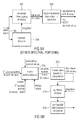
- Fig. 1a illustrates an apparatus for encoding an audio signal 99.
- the audio signal 99 is input into a time spectrum converter 100 for converting an audio signal having a sampling rate into a spectral representation 101 output by the time spectrum converter.
- the spectrum 101 is input into a spectral analyzer 102 for analyzing the spectral representation 101.
- the spectral analyzer 101 is configured for determining a first set of first spectral portions 103 to be encoded with a first spectral resolution and a different second set of second spectral portions 105 to be encoded with a second spectral resolution.
- the second spectral resolution is smaller than the first spectral resolution.
- the second set of second spectral portions 105 is input into a parameter calculator or parametric coder 104 for calculating spectral envelope information having the second spectral resolution. Furthermore, a spectral domain audio coder 106 is provided for generating a first encoded representation 107 of the first set of first spectral portions having the first spectral resolution. Furthermore, the parameter calculator/parametric coder 104 is configured for generating a second encoded representation 109 of the second set of second spectral portions. The first encoded representation 107 and the second encoded representation 109 are input into a bit stream multiplexer or bit stream former 108 and block 108 finally outputs the encoded audio signal for transmission or storage on a storage device.
- a first spectral portion such as 306 of Fig. 3a will be surrounded by two second spectral portions such as 307a, 307b. This is not the case in HE AAC, where the core coder frequency range is band limited
- Fig. 1b illustrates a decoder matching with the encoder of Fig. 1 a.
- the first encoded representation 107 is input into a spectral domain audio decoder 112 for generating a first decoded representation of a first set of first spectral portions, the decoded representation having a first spectral resolution.
- the second encoded representation 109 is input into a parametric decoder 114 for generating a second decoded representation of a second set of second spectral portions having a second spectral resolution being lower than the first spectral resolution.
- the decoder further comprises a frequency regenerator 116 for regenerating a reconstructed second spectral portion having the first spectral resolution using a first spectral portion.
- the frequency regenerator 116 performs a tile filling operation, i.e., uses a tile or portion of the first set of first spectral portions and copies this first set of first spectral portions into the reconstruction range or reconstruction band having the second spectral portion and typically performs spectral envelope shaping or another operation as indicated by the decoded second representation output by the parametric decoder 114, i.e., by using the information on the second set of second spectral portions.
- the decoded first set of first spectral portions and the reconstructed second set of spectral portions as indicated at the output of the frequency regenerator 116 on line 117 is input into a spectrum-time converter 118 configured for converting the first decoded representation and the reconstructed second spectral portion into a time representation 119, the time representation having a certain high sampling rate.
- Fig. 2b illustrates an implementation of the Fig. 1 a encoder.
- An audio input signal 99 is input into an analysis filterbank 220 corresponding to the time spectrum converter 100 of
- a temporal noise shaping operation is performed in TNS block 222. Therefore, the input into the spectral analyzer 102 of Fig. 1 a corresponding to a block tonal mask 226 of Fig. 2b can either be full spectral values, when the temporal noise shaping/ temporal tile shaping operation is not applied or can be spectral residual values, when the TNS operation as illustrated in Fig. 2b , block 222 is applied.
- a joint channel coding 228 can additionally be performed, so that the spectral domain encoder 106 of Fig. 1 a may comprise the joint channel coding block 228.
- an entropy coder 232 for performing a lossless data compression is provided which is also a portion of the spectral domain encoder 106 of Fig. 1a .
- the spectral analyzer/tonal mask 226 separates the output of TNS block 222 into the core band and the tonal components corresponding to the first set of first spectral portions 103 and the residual components corresponding to the second set of second spectral portions 105 of Fig. 1 a.
- the block 224 indicated as IGF parameter extraction encoding corresponds to the parametric coder 104 of Fig. 1 a and the bitstream multiplexer 230 corresponds to the bitstream multiplexer 108 of Fig. 1a .
- the analysis filterbank 222 is implemented as an MDCT (modified discrete cosine transform filterbank) and the MDCT is used to transform the signal 99 into a time-frequency domain with the modified discrete cosine transform acting as the frequency analysis tool.
- MDCT modified discrete cosine transform filterbank
- the spectral analyzer 226 preferably applies a tonality mask.
- This tonality mask estimation stage is used to separate tonal components from the noise-like components in the signal. This allows the core coder 228 to code all tonal components with a psycho-acoustic module.
- the tonality mask estimation stage can be implemented in numerous different ways and is preferably implemented similar in its functionality to the sinusoidal track estimation stage used in sine and noise-modeling for speech/audio coding [8, 9] or an HILN model based audio coder described in [10].
- an implementation is used which is easy to implement without the need to maintain birth-death trajectories, but any other tonality or noise detector can be used as well.
- the IGF module calculates the similarity that exists between a source region and a target region.
- the target region will be represented by the spectrum from the source region.
- the measure of similarity between the source and target regions is done using a cross-correlation approach.
- the target region is split into nTar non-overlapping frequency tiles. For every tile in the target region, nSrc source tiles are created from a fixed start frequency. These source tiles overlap by a factor between 0 and 1, where 0 means 0% overlap and 1 means 100% overlap. Each of these source tiles is correlated with the target tile at various lags to find the source tile that best matches the target tile.
- the best matching tile number is stored in tileNum [ idx_tar ]
- the lag at which it best correlates with the target is stored in xcorr_lag [ idx_tar ][ idx_src ]
- the sign of the correlation is stored in xcorr_sign [ idx_tar ][ idx_src ] .
- the source tile needs to be multiplied by -1 before the tile filling process at the decoder.
- the IGF module also takes care of not overwriting the tonal components in the spectrum since the tonal components are preserved using the tonality mask.
- a band-wise energy parameter is used to store the energy of the target region enabling us to reconstruct the spectrum accurately.
- This method has certain advantages over the classical SBR [1] in that the harmonic grid of a multi-tone signal is preserved by the core coder while only the gaps between the sinusoids is filled with the best matching "shaped noise" from the source region.
- Another advantage of this system compared to ASR (Accurate Spectral Replacement) [2-4] is the absence of a signal synthesis stage which creates the important portions of the signal at the decoder. Instead, this task is taken over by the core coder, enabling the preservation of important components of the spectrum.
- Another advantage of the proposed system is the continuous scalability that the features offer.
- tile choice stabilization technique which removes frequency domain artifacts such as trilling and musical noise.
- the encoder analyses each destination region energy band, typically performing a cross-correlation of the spectral values and if a certain threshold is exceeded, sets a joint flag for this energy band.
- the left and right channel energy bands are treated individually if this joint stereo flag is not set.
- the joint stereo flag is set, both the energies and the patching are performed in the joint stereo domain.
- the joint stereo information for the IGF regions is signaled similar the joint stereo information for the core coding, including a flag indicating in case of prediction if the direction of the prediction is from downmix to residual or vice versa.
- the energies can be calculated from the transmitted energies in the L/R-domain.
- midNrg k leftNrg k + rightNrg k ;
- sideNrg k leftNrg k - rightNrg k ; with k being the frequency index in the transform domain.
- Another solution is to calculate and transmit the energies directly in the joint stereo domain for bands where joint stereo is active, so no additional energy transformation is needed at the decoder side.
- This processing ensures that from the tiles used for regenerating highly correlated destination regions and panned destination regions, the resulting left and right channels still represent a correlated and panned sound source even if the source regions are not correlated, preserving the stereo image for such regions.
- joint stereo flags are transmitted that indicate whether L/R or M/S as an example for the general joint stereo coding shall be used.
- the core signal is decoded as indicated by the joint stereo flags for the core bands.
- the core signal is stored in both L/R and M/S representation.
- the source tile representation is chosen to fit the target tile representation as indicated by the joint stereo information for the IGF bands.
- TNS Temporal Noise Shaping
- IGF is based on an MDCT representation. For efficient coding, preferably long blocks of approx. 20 ms have to be used. If the signal within such a long block contains transients, audible pre- and post-echoes occur in the IGF spectral bands due to the tile filling.
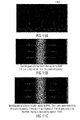
- Fig. 7c shows a typical pre-echo effect before the transient onset due to IGF. On the left side, the spectrogram of the original signal is shown and on the right side the spectrogram of the bandwidth extended signal without TNS filtering is shown.
- TNS temporal tile shaping
- the required TTS prediction coefficients are calculated and applied using the full spectrum on encoder side as usual.
- the TNS/TTS start and stop frequencies are not affected by the IGF start frequency f IGFstart of the IGF tool.
- the TTS stop frequency is increased to the stop frequency of the IGF tool, which is higher than f IGFstart .
- the TNS/TTS coefficients are applied on the full spectrum again, i.e.
- TTS the core spectrum plus the regenerated spectrum plus the tonal components from the tonality map (see Fig. 7e).
- the application of TTS is necessary to form the temporal envelope of the regenerated spectrum to match the envelope of the original signal again. So the shown pre-echoes are reduced. In addition, it still shapes the quantization noise in the signal below f IGFstart as usual with TNS.
- spectral patching on an audio signal corrupts spectral correlation at the patch borders and thereby impairs the temporal envelope of the audio signal by introducing dispersion.
- another benefit of performing the IGF tile filling on the residual signal is that, after application of the shaping filter, tile borders are seamlessly correlated, resulting in a more faithful temporal reproduction of the signal.
- the spectrum having undergone TNS/TTS filtering, tonality mask processing and IGF parameter estimation is devoid of any signal above the IGF start frequency except for tonal components.
- This sparse spectrum is now coded by the core coder using principles of arithmetic coding and predictive coding. These coded components along with the signaling bits form the bitstream of the audio.
- Fig. 2a illustrates the corresponding decoder implementation.
- the bitstream in Fig. 2a corresponding to the encoded audio signal is input into the demultiplexer/decoder which would be connected, with respect to Fig. 1b , to the blocks 112 and 114.
- the bitstream demultiplexer separates the input audio signal into the first encoded representation 107 of Fig. 1b and the second encoded representation 109 of Fig. 1 b.
- the first encoded representation having the first set of first spectral portions is input into the joint channel decoding block 204 corresponding to the spectral domain decoder 112 of Fig. 1 b.
- the second encoded representation is input into the parametric decoder 114 not illustrated in Fig.
- IGF block 202 corresponding to the frequency regenerator 116 of Fig. 1 b.
- the first set of first spectral portions required for frequency regeneration are input into IGF block 202 via line 203.
- the specific core decoding is applied in the tonal mask block 206 so that the output of tonal mask 206 corresponds to the output of the spectral domain decoder 112.
- a combination by combiner 208 is performed, i.e., a frame building where the output of combiner 208 now has the full range spectrum, but still in the TNS/TTS filtered domain.
- an inverse TNS/TTS operation is performed using TNS/TTS filter information provided via line 109, i.e., the TTS side information is preferably included in the first encoded representation generated by the spectral domain encoder 106 which can, for example, be a straightforward AAC or USAC core encoder, or can also be included in the second encoded representation.
- the spectral domain encoder 106 can, for example, be a straightforward AAC or USAC core encoder, or can also be included in the second encoded representation.
- a complete spectrum until the maximum frequency is provided which is the full range frequency defined by the sampling rate of the original input signal.
- a spectrum/time conversion is performed in the synthesis filterbank 212 to finally obtain the audio output signal.
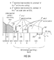
- Fig. 3a illustrates a schematic representation of the spectrum.
- the spectrum is subdivided in scale factor bands SCB where there are seven scale factor bands SCB1 to SCB7 in the illustrated example of Fig. 3a .
- the scale factor bands can be AAC scale factor bands which are defined in the AAC standard and have an increasing bandwidth to upper frequencies as illustrated in Fig. 3a schematically. It is preferred to perform intelligent gap filling not from the very beginning of the spectrum, i.e., at low frequencies, but to start the IGF operation at an IGF start frequency illustrated at 309. Therefore, the core frequency band extends from the lowest frequency to the IGF start frequency.
- Fig. 3a illustrates a spectrum which is exemplarily input into the spectral domain encoder 106 or the joint channel coder 228, i.e., the core encoder operates in the full range, but encodes a significant amount of zero spectral values, i.e., these zero spectral values are quantized to zero or are set to zero before quantizing or subsequent to quantizing.
- the core encoder operates in full range, i.e., as if the spectrum would be as illustrated, i.e., the core decoder does not necessarily have to be aware of any intelligent gap filling or encoding of the second set of second spectral portions with a lower spectral resolution.
- the high resolution is defined by a line-wise coding of spectral lines such as MDCT lines
- the second resolution or low resolution is defined by, for example, calculating only a single spectral value per scale factor band, where a scale factor band covers several frequency lines.
- the second low resolution is, with respect to its spectral resolution, much lower than the first or high resolution defined by the line-wise coding typically applied by the core encoder such as an AAC or USAC core encoder.
- the encoder is a core encoder and due to the fact that there can, but does not necessarily have to be, components of the first set of spectral portions in each band, the core encoder calculates a scale factor for each band not only in the core range below the IGF start frequency 309, but also above the IGF start frequency until the maximum frequency f IGFstop which is smaller or equal to the half of the sampling frequency, i.e., f s/2 .
- the encoded tonal portions 302, 304, 305, 306, 307 of Fig. 3a and, in this embodiment together with the scale factors SCB1 to SCB7 correspond to the high resolution spectral data.
- the low resolution spectral data are calculated starting from the IGF start frequency and correspond to the energy information values E 1 , E 2 , E 3 , E 4 , which are transmitted together with the scale factors SF4 to SF7.
- an additional noise-filling operation in the core band i.e., lower in frequency than the IGF start frequency, i.e., in scale factor bands SCB1 to SCB3 can be applied in addition.
- noise-filling there exist several adjacent spectral lines which have been quantized to zero. On the decoder-side, these quantized to zero spectral values are re-synthesized and the re-synthesized spectral values are adjusted in their magnitude using a noise-filling energy such as NF 2 illustrated at 308 in Fig. 3b .
- noise-filling energy which can be given in absolute terms or in relative terms particularly with respect to the scale factor as in USAC corresponds to the energy of the set of spectral values quantized to zero.
- These noise-filling spectral lines can also be considered to be a third set of third spectral portions which are regenerated by straightforward noise-filling synthesis without any IGF operation relying on frequency regeneration using frequency tiles from other frequencies for reconstructing frequency tiles using spectral values from a source range and the energy information E 1 , E 2 , E 3 , E 4 .
- the bands, for which energy information is calculated coincide with the scale factor bands.
- an energy information value grouping is applied so that, for example, for scale factor bands 4 and 5, only a single energy information value is transmitted, but even in this embodiment, the borders of the grouped reconstruction bands coincide with borders of the scale factor bands. If different band separations are applied, then certain re-calculations or synchronization calculations may be applied, and this can make sense depending on the certain implementation.
- the spectral domain encoder 106 of Fig. 1 a is a psycho-acoustically driven encoder as illustrated in Fig. 4a .
- the to be encoded audio signal after having been transformed into the spectral range (401 in Fig. 4a ) is forwarded to a scale factor calculator 400.
- the scale factor calculator is controlled by a psycho-acoustic model additionally receiving the to be quantized audio signal or receiving, as in the MPEG1/2 Layer 3 or MPEG AAC standard, a complex spectral representation of the audio signal.
- the psycho-acoustic model calculates, for each scale factor band, a scale factor representing the psycho-acoustic threshold.
- the scale factors are then, by cooperation of the well-known inner and outer iteration loops or by any other suitable encoding procedure adjusted so that certain bitrate conditions are fulfilled. Then, the to be quantized spectral values on the one hand and the calculated scale factors on the other hand are input into a quantizer processor 404. In the straightforward audio encoder operation, the to be quantized spectral values are weighted by the scale factors and, the weighted spectral values are then input into a fixed quantizer typically having a compression functionality to upper amplitude ranges.
- quantization indices which are then forwarded into an entropy encoder typically having specific and very efficient coding for a set of zero-quantization indices for adjacent frequency values or, as also called in the art, a "run" of zero values.
- the quantizer processor typically receives information on the second spectral portions from the spectral analyzer.
- the quantizer processor 404 makes sure that, in the output of the quantizer processor 404, the second spectral portions as identified by the spectral analyzer 102 are zero or have a representation acknowledged by an encoder or a decoder as a zero representation which can be very efficiently coded, specifically when there exist "runs" of zero values in the spectrum.
- Fig. 4b illustrates an implementation of the quantizer processor.
- the MDCT spectral values can be input into a set to zero block 410. Then, the second spectral portions are already set to zero before a weighting by the scale factors in block 412 is performed.
- block 410 is not provided, but the set to zero cooperation is performed in block 418 subsequent to the weighting block 412.
- the set to zero operation can also be performed in a set to zero block 422 subsequent to a quantization in the quantizer block 420.
- blocks 410 and 418 would not be present. Generally, at least one of the blocks 410, 418, 422 are provided depending on the specific implementation.
- a quantized spectrum is obtained corresponding to what is illustrated in Fig. 3a .
- This quantized spectrum is then input into an entropy coder such as 232 in Fig. 2b which can be a Huffman coder or an arithmetic coder as, for example, defined in the USAC standard.
- the set to zero blocks 410, 418, 422, which are provided alternatively to each other or in parallel are controlled by the spectral analyzer 424.
- the spectral analyzer preferably comprises any implementation of a well-known tonality detector or comprises any different kind of detector operative for separating a spectrum into components to be encoded with a high resolution and components to be encoded with a low resolution.
- Other such algorithms implemented in the spectral analyzer can be a voice activity detector, a noise detector, a speech detector or any other detector deciding, depending on spectral information or associated metadata on the resolution requirements for different spectral portions.
- Fig. 5a illustrates a preferred implementation of the time spectrum converter 100 of Fig. 1 a as, for example, implemented in AAC or USAC.
- the time spectrum converter 100 comprises a windower 502 controlled by a transient detector 504.
- the windower 502 calculates, for overlapping blocks, windowed frames, where each windowed frame typically has two N values such as 2048 values.
- a transformation within a block transformer 506 is performed, and this block transformer typically additionally provides a decimation, so that a combined decimation/transform is performed to obtain a spectral frame with N values such as MDCT spectral values.
- the frame at the input of block 506 comprises two N values such as 2048 values and a spectral frame then has 1024 values.
- Fig. 5b illustrating a specific implementation of frequency regenerator 116 and the spectrum-time converter 118 of Fig. 1b , or of the combined operation of blocks 208, 212 of Fig. 2a .
- a specific reconstruction band is considered such as scale factor band 6 of Fig. 3a .
- the first spectral portion in this reconstruction band i.e., the first spectral portion 306 of Fig. 3a is input into the frame builder/adjustor block 510.
- a reconstructed second spectral portion for the scale factor band 6 is input into the frame builder/adjuster 510 as well.
- energy information such as E 3 of Fig.
- 3b for a scale factor band 6 is also input into block 510.
- the reconstructed second spectral portion in the reconstruction band has already been generated by frequency tile filling using a source range and the reconstruction band then corresponds to the target range.
- an energy adjustment of the frame is performed to then finally obtain the complete reconstructed frame having the N values as, for example, obtained at the output of combiner 208 of Fig. 2a .
- an inverse block transform/interpolation is performed to obtain 248 time domain values for the for example 124 spectral values at the input of block 512.
- a synthesis windowing operation is performed in block 514 which is again controlled by a long window/short window indication transmitted as side information in the encoded audio signal.
- an overlap/add operation with a previous time frame is performed.
- MDCT applies a 50% overlap so that, for each new time frame of 2N values, N time domain values are finally output.
- a 50% overlap is heavily preferred due to the fact that it provides critical sampling and a continuous crossover from one frame to the next frame due to the overlap/add operation in block 516.
- a noise-filling operation can additionally be applied not only below the IGF start frequency, but also above the IGF start frequency such as for the contemplated reconstruction band coinciding with scale factor band 6 of Fig. 3a .
- noise-filling spectral values can also be input into the frame builder/adjuster 510 and the adjustment of the noise-filling spectral values can also be applied within this block or the noise-filling spectral values can already be adjusted using the noise-filling energy before being input into the frame builder/adjuster 510.
- an IGF operation i.e., a frequency tile filling operation using spectral values from other portions can be applied in the complete spectrum.
- a spectral tile filling operation can not only be applied in the high band above an IGF start frequency but can also be applied in the low band.
- the noise-filling without frequency tile filling can also be applied not only below the IGF start frequency but also above the IGF start frequency. It has, however, been found that high quality and high efficient audio encoding can be obtained when the noise-filling operation is limited to the frequency range below the IGF start frequency and when the frequency tile filling operation is restricted to the frequency range above the IGF start frequency as illustrated in Fig. 3a .
- the target tiles (TT) (having frequencies greater than the IGF start frequency) are bound to scale factor band borders of the full rate coder.
- the size of the ST should correspond to the size of the associated TT. This is illustrated using the following example.
- TT[0] has a length of 10 MDCT Bins. This exactly corresponds to the length of two subsequent SCBs (such as 4 + 6). Then, all possible ST that are to be correlated with TT[0], have a length of 10 bins, too.
- a second target tile TT[1] being adjacent to TT[0] has a length of 15 bins I (SCB having a length of 7 + 8). Then, the ST for that have a length of 15 bins rather than 10 bins as for TT[0].
- Block 522 is a frequency tile generator receiving, not only a target band ID, but additionally receiving a source band ID.
- a source band ID Exemplarily, it has been determined on the encoder-side that the scale factor band 3 of Fig. 3a is very well suited for reconstructing scale factor band 7. Thus, the source band ID would be 2 and the target band ID would be 7.
- the frequency tile generator 522 applies a copy up or harmonic tile filling operation or any other tile filling operation to generate the raw second portion of spectral components 523.
- the raw second portion of spectral components has a frequency resolution identical to the frequency resolution included in the first set of first spectral portions.
- the first spectral portion of the reconstruction band such as 307 of Fig. 3a is input into a frame builder 524 and the raw second portion 523 is also input into the frame builder 524.
- the reconstructed frame is adjusted by the adjuster 526 using a gain factor for the reconstruction band calculated by the gain factor calculator 528.
- the first spectral portion in the frame is not influenced by the adjuster 526, but only the raw second portion for the reconstruction frame is influenced by the adjuster 526.
- the gain factor calculator 528 analyzes the source band or the raw second portion 523 and additionally analyzes the first spectral portion in the reconstruction band to finally find the correct gain factor 527 so that the energy of the adjusted frame output by the adjuster 526 has the energy E 4 when a scale factor band 7 is contemplated.
- the spectral analyzer is also implemented to calculating similarities between first spectral portions and second spectral portions and to determine, based on the calculated similarities, for a second spectral portion in a reconstruction range a first spectral portion matching with the second spectral portion as far as possible. Then, in this variable source range/destination range implementation, the parametric coder will additionally introduce into the second encoded representation a matching information indicating for each destination range a matching source range. On the decoder-side, this information would then be used by a frequency tile generator 522 of Fig. 5c illustrating a generation of a raw second portion 523 based on a source band ID and a target band ID. Furthermore, as illustrated in Fig. 3a , the spectral analyzer is configured to analyze the spectral representation up to a maximum analysis frequency being only a small amount below half of the sampling frequency and preferably being at least one quarter of the sampling frequency or typically higher.
- the encoder operates without downsampling and the decoder operates without upsampling.
- the spectral domain audio coder is configured to generate a spectral representation having a Nyquist frequency defined by the sampling rate of the originally input audio signal.
- the spectral analyzer is configured to analyze the spectral representation starting with a gap filling start frequency and ending with a maximum frequency represented by a maximum frequency included in the spectral representation, wherein a spectral portion extending from a minimum frequency up to the gap filling start frequency belongs to the first set of spectral portions and wherein a further spectral portion such as 304, 305, 306, 307 having frequency values above the gap filling frequency additionally is included in the first set of first spectral portions.
- the spectral domain audio decoder 112 is configured so that a maximum frequency represented by a spectral value in the first decoded representation is equal to a maximum frequency included in the time representation having the sampling rate wherein the spectral value for the maximum frequency in the first set of first spectral portions is zero or different from zero.
- a scale factor for the scale factor band exists, which is generated and transmitted irrespective of whether all spectral values in this scale factor band are set to zero or not as discussed in the context of Figs. 3a and 3b .
- the invention is, therefore, advantageous that with respect to other parametric techniques to increase compression efficiency, e.g. noise substitution and noise filling (these techniques are exclusively for efficient representation of noise like local signal content) the invention allows an accurate frequency reproduction of tonal components.
- noise substitution and noise filling these techniques are exclusively for efficient representation of noise like local signal content
- the invention allows an accurate frequency reproduction of tonal components.
- no state-of-the-art technique addresses the efficient parametric representation of arbitrary signal content by spectral gap filling without the restriction of a fixed a-priory division in low band (LF) and high band (HF).
- Embodiments of the inventive system improve the state-of-the-art approaches and thereby provides high compression efficiency, no or only a small perceptual annoyance and full audio bandwidth even for low bitrates.
- the general system consists of
- a first step towards a more efficient system is to remove the need for transforming spectral data into a second transform domain different from the one of the core coder.
- AAC audio codecs
- AAC audio codecs
- a second requirement for the BWE system would be the need to preserve the tonal grid whereby even HF tonal components are preserved and the quality of the coded audio is thus superior to the existing systems.
- IGF Intelligent Gap Filling
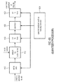
- Fig. 9a illustrates an apparatus for decoding an encoded audio signal comprising an encoded representation of a first set of first spectral portions and an encoded representation of parametric data indicating spectral energies for a second set of second spectral portions.
- the first set of first spectral portions is indicated at 901 a in Fig. 9a
- the encoded representation of the parametric data is indicated at 901 b in Fig. 9a .
- An audio decoder 900 is provided for decoding the encoded representation 901 a of the first set of first spectral portions to obtain a decoded first set of first spectral portions 904 and for decoding the encoded representation of the parametric data to obtain a decoded parametric data 902 for the second set of second spectral portions indicating individual energies for individual reconstruction bands, where the second spectral portions are located in the reconstruction bands.
- a frequency regenerator 906 is provided for reconstructing spectral values of a reconstruction band comprising a second spectral portion. The frequency regenerator 906 uses a first spectral portion of the first set of first spectral portions and an individual energy information for the reconstruction band, where the reconstruction band comprises a first spectral portion and the second spectral portion.
- the frequency regenerator 906 comprises a calculator 912 for determining a survive energy information comprising an accumulated energy of the first spectral portion having frequencies in the reconstruction band. Furthermore, the frequency regenerator 906 comprises a calculator 918 for determining a tile energy information of further spectral portions of the reconstruction band and for frequency values being different from the first spectral portion, where these frequency values have frequencies in the reconstruction band, wherein the further spectral portions are to be generated by frequency regeneration using a first spectral portion different from the first spectral portion in the reconstruction band.
- the frequency regenerator 906 further comprises a calculator 914 for a missing energy in the reconstruction band, and the calculator 914 operates using the individual energy for the reconstruction band and the survive energy generated by block 912. Furthermore, the frequency regenerator 906 comprises a spectral envelope adjuster 916 for adjusting the further spectral portions in the reconstruction band based on the missing energy information and the tile energy information generated by block 918.
- Fig. 9c illustrating a certain reconstruction band 920.
- the reconstruction band comprises a first spectral portion in the reconstruction band such as the first spectral portion 306 in Fig. 3a schematically illustrated at 921.
- the rest of the spectral values in the reconstruction band 920 are to be generated using a source region, for example, from the scale factor band 1, 2, 3 below the intelligent gap filling start frequency 309 of Fig. 3a .
- the frequency regenerator 906 is configured for generating raw spectral values for the second spectral portions 922 and 923. Then, a gain factor g is calculated as illustrated in Fig.
- the first spectral portion in the reconstruction band illustrated at 921 in Fig. 9c is decoded by the audio decoder 900 and is not influenced by the envelope adjustment performed block 916 of Fig. 9b . Instead, the first spectral portion in the reconstruction band indicated at 921 is left as it is, since this first spectral portion is output by the full bandwidth or full rate audio decoder 900 via line 904.
- the energy value E3 for the reconstruction band corresponding to scale factor band 6 of Fig. 3b or Fig. 3a is equal to 10 units.
- the energy value not only comprises the energy of the spectral portions 922, 923, but the full energy of the reconstruction band 920 as calculated on the encoder-side, i.e., before performing the spectral analysis using, for example, the tonality mask. Therefore, the ten energy units cover the first and the second spectral portions in the reconstruction band.
- the energy of the source range data for blocks 922, 923 or for the raw target range data for block 922, 923 is equal to eight energy units. Thus, a missing energy of five units is calculated.
- a gain factor of 0.79 is calculated. Then, the raw spectral lines for the second spectral portions 922, 923 are multiplied by the calculated gain factor. Thus, only the spectral values for the second spectral portions 922, 923 are adjusted and the spectral lines for the first spectral portion 921 are not influenced by this envelope adjustment. Subsequent to multiplying the raw spectral values for the second spectral portions 922, 923, a complete reconstruction band has been calculated consisting of the first spectral portions in the reconstruction band, and consisting of spectral lines in the second spectral portions 922, 923 in the reconstruction band 920.
- the source range for generating the raw spectral data in bands 922, 923 is, with respect to frequency, below the IGF start frequency 309 and the reconstruction band 920 is above the IGF start frequency 309.
- a reconstruction band has, in one embodiment, the size of corresponding scale factor bands of the core audio decoder or are sized so that, when energy pairing is applied, an energy value for a reconstruction band provides the energy of two or a higher integer number of scale factor bands.
- the lower frequency border of the reconstruction band 920 is equal to the lower border of scale factor band 4 and the higher frequency border of the reconstruction band 920 coincides with the higher border of scale factor band 6.
- Fig. 9d is discussed in order to show further functionalities of the decoder of Fig. 9a .
- the audio decoder 900 receives the dequantized spectral values corresponding to first spectral portions of the first set of spectral portions and, additionally, scale factors for scale factor bands such as illustrated in Fig. 3b are provided to an inverse scaling block 940.
- the inverse scaling block 940 provides all first sets of first spectral portions below the IGF start frequency 309 of Fig. 3a and, additionally, the first spectral portions above the IGF start frequency, i.e., the first spectral portions 304, 305, 306, 307 of Fig. 3a which are all located in a reconstruction band as illustrated at 941 in Fig.
- the first spectral portions in the source band used for frequency tile filling in the reconstruction band are provided to the envelope adjuster/calculator 942 and this block additionally receives the energy information for the reconstruction band provided as parametric side information to the encoded audio signal as illustrated at 943 in Fig. 9d .
- the envelope adjuster/calculator 942 provides the functionalities of Fig. 9b and 9c and finally outputs adjusted spectral values for the second spectral portions in the reconstruction band.
- These adjusted spectral values 922, 923 for the second spectral portions in the reconstruction band and the first spectral portions 921 in the reconstruction band indicated that line 941 in Fig. 9d jointly represent the complete spectral representation of the reconstruction band.
- the encoder comprises a time/spectrum converter 1002 feeding a spectral analyzer 1004, and the spectral analyzer 1004 is connected to a parameter calculator 1006 on the one hand and an audio encoder 1008 on the other hand.
- the audio encoder 1008 provides the encoded representation of a first set of first spectral portions and does not cover the second set of second spectral portions.
- the parameter calculator 1006 provides energy information for a reconstruction band covering the first and second spectral portions.
- the audio encoder 1008 is configured for generating a first encoded representation of the first set of first spectral portions having the first spectral resolution, where the audio encoder 1008 provides scale factors for all bands of the spectral representation generated by block 1002. Additionally, as illustrated in Fig. 3b , the encoder provides energy information at least for reconstruction bands located, with respect to frequency, above the IGF start frequency 309 as illustrated in Fig. 3a . Thus, for reconstruction bands preferably coinciding with scale factor bands or with groups of scale factor bands, two values are given, i.e., the corresponding scale factor from the audio encoder 1008 and, additionally, the energy information output by the parameter calculator 1006.
- the audio encoder preferably has scale factor bands with different frequency bandwidths, i.e., with a different number of spectral values. Therefore, the parametric calculator comprise a normalizer 1012 for normalizing the energies for the different bandwidth with respect to the bandwidth of the specific reconstruction band. To this end, the normalizer 1012 receives, as inputs, an energy in the band and a number of spectral values in the band and the normalizer 1012 then outputs a normalized energy per reconstruction/scale factor band.
- the parametric calculator 1006a of Fig. 10a comprises an energy value calculator receiving control information from the core or audio encoder 1008 as illustrated by line 1007 in Fig. 10a .
- This control information may comprise information on long/short blocks used by the audio encoder and/or grouping information.
- the grouping information may additionally refer to a spectral grouping, i.e., the grouping of two scale factor bands into a single reconstruction band.
- the energy value calculator 1014 outputs a single energy value for each grouped band covering a first and a second spectral portion when only the spectral portions have been grouped.
- Fig. 10d illustrates a further embodiment for implementing the spectral grouping.
- block 1016 is configured for calculating energy values for two adjacent bands.
- the energy values for the adjacent bands are compared and, when the energy values are not so much different or less different than defined by, for example, a threshold, then a single (normalized) value for both bands is generated as indicated in block 1020.
- the block 1018 can be bypassed.
- the generation of a single value for two or more bands performed by block 1020 can be controlled by an encoder bitrate control 1024.
- the encoded bitrate control 1024 controls block 1020 to generate a single normalized value for two or more bands even though the comparison in block 1018 would not have been allowed to group the energy information values.
- the audio encoder is performing the grouping of two or more short windows, this grouping is applied for the energy information as well.
- the core encoder performs a grouping of two or more short blocks, then, for these two or more blocks, only a single set of scale factors is calculated and transmitted.
- the audio decoder then applies the same set of scale factors for both grouped windows.
- the spectral values in the reconstruction band are accumulated over two or more short windows.
- the envelope adjustment discussed with respect to Fig. 9a to 9d is not performed individually for each short block but is performed together for the set of grouped short windows.
- the corresponding normalization is then again applied so that even though any grouping in frequency or grouping in time has been performed, the normalization easily allows that, for the energy value information calculation on the decoder-side, only the energy information value on the one hand and the amount of spectral lines in the reconstruction band or in the set of grouped reconstruction bands has to be known.
- an information on spectral energies, an information on individual energies or an individual energy information, an information on a survive energy or a survive energy information, an information a tile energy or a tile energy information, or an information on a missing energy or a missing energy information may comprise not only an energy value, but also an (e.g. absolute) amplitude value, a level value or any other value, from which a final energy value can be derived.
- the information on an energy may e.g. comprise the energy value itself, and/or a value of a level and/or of an amplitude and/or of an absolute amplitude.
- Fig. 12a illustrates a further implementation of the apparatus for decoding.
- a bitstream is received by a core decoder 1200 which can, for example, be an AAC decoder.
- the result is configured into a stage for performing a bandwidth extension patching or tiling 1202 corresponding to the frequency regenerator 604 for example.
- a procedure of patch/tile adaption and post-processing is performed, and, when a patch adaption has been performed, the frequency regenerator 1202 is controlled to perform a further frequency regeneration, but now with, for example adjusted frequency borders.
- the result is then forwarded to block 1206 performing the parameter-driven bandwidth envelope shaping as, for example, also discussed in the context of block 712 or 826.
- the result is then forwarded to a synthesis transform block 1208 for performing a transform into the final output domain which is, for example, a PCM output domain as illustrated in Fig. 12a .
- Fig. 12b shows how the newly proposed technique reduces artifacts found in state-of-the-art BWE methods.
- Fig. 12 panel (2) the stylized magnitude spectrum of the output of a contemporary BWE method is shown.
- the signal is perceptually impaired by the beating caused by to two nearby tones, and also by the splitting of a tone. Both problematic spectral areas are marked with a circle each.
- the new technique first detects the spectral location of the tonal components contained in the signal. Then, according to one aspect of the invention, it is attempted to adjust the transition frequencies between LF and all patches by individual shifts (within given limits) such that splitting or beating of tonal components is minimized. For that purpose, the transition frequency preferably has to match a local spectral minimum. This step is shown in Fig. 12b panel (2) and panel (3), where the transition frequency f x2 is shifted towards higher frequencies, resulting in f' x2 .
- At least one of the misplaced tonal components is removed to reduce either the beating artifact at the transition frequencies or the warbling. This is done via spectral extrapolation or interpolation / filtering, as shown in Figure 2 panel (3). A tonal component is thereby removed from foot-point to foot-point, i.e. from its left local minimum to its right local minimum. The resulting spectrum after the application of the inventive technology is shown in Fig. 12b panel (4).
- Fig. 12b illustrates, in the upper left corner, i.e., in panel (1), the original signal.
- the upper right corner i.e., in panel (2)
- a comparison bandwidth extended signal with problematic areas marked by ellipses 1220 and 1221 is shown.
- the lower left corner i.e., in panel (3)
- two preferred patch or frequency tile processing features are illustrated.
- the splitting of tonal portions has been addressed by increasing the frequency border f' x2 so that a clipping of the corresponding tonal portion is not there anymore.
- gain functions 1030 for eliminating the tonal portion 1031 and 1032 are applied or, alternatively, an interpolation illustrated by 1033 is indicated.
- the lower right corner of Fig. 12b i.e., panel (4) depicts the improved signal resulting from a combination of tile/patch frequency adjusting on the one hand and elimination or at least attenuation of problematic tonal portions.
- Panel (1) of Fig. 12b illustrates, as discussed before, the original spectrum, and the original spectrum has a core frequency range up to the cross-over or gap filing start frequency fx1 .
- a frequency f x1 illustrates a border frequency 1250 between the source range 1252 and a reconstruction range 1254 extending between the border frequency 1250 and a maximum frequency which is smaller than or equal to the Nyquist frequency f Nyquist .
- a signal is bandwidth-limited at f x1 or, when the technology regarding intelligent gap filling is applied, it is assumed that f x1 corresponds to the gap filling start frequency 309 of Fig. 3a .
- the reconstruction range above f x1 will be empty (in case of the Fig. 13a, 13b implementation) or will comprise certain first spectral portions to be encoded with a high resolution as discussed in the context of Fig. 3a .
- panel (2) illustrates a preliminary regenerated signal, for example generated by block 702 of Fig. 7a which has two problematic portions.
- One problematic portion is illustrated at 1220.
- the frequency distance between the tonal portion within the core region illustrated at 1220a and the tonal portion at the start of the frequency tile illustrated at 1220b is too small so that a beating artifact would be created.
- the further problem is that at the upper border of the first frequency tile generated by the first patching operation or frequency tiling operation illustrated at 1225 is a halfway-clipped or split tonal portion 1226. When this tonal portion 1226 is compared to the other tonal portions in Fig.
- Fig. 12b illustrates a sequential application of the transition frequency adjustment 706 and the removal of tonal components at borders illustrated at 708.
- transition border f x1 Another option would have been to set the transition border f x1 so that it is a little bit lower so that the tonal portion 1220a is not in the core range anymore. Then, the tonal portion 1220a has also been removed or eliminated by setting the transition frequency f x1 at a lower value.
- the beating problem depends on the amplitudes and the distance in frequency of adjacent tonal portions.
- the detector 704, 720 or stated more general, the analyzer 602 is preferably configured in such a way that an analysis of the lower spectral portion located in the frequency below the transition frequency such as f X1 , f x2 , f' x2 is analyzed in order to locate any tonal component. Furthermore, the spectral range above the transition frequency is also analyzed in order to detect a tonal component. When the detection results in two tonal components, one to the left of the transition frequency with respect to frequency and one to the right (with respect to ascending frequency), then the remover of tonal components at borders illustrated at 708 in Fig. 7a is activated.
- the detection of tonal components is performed in a certain detection range which extends, from the transition frequency, in both directions at least 20% with respect to the bandwidth of the corresponding band and preferably only extends up to 10% downwards to the left of the transition frequency and upwards to the right of the transition frequency related to the corresponding bandwidth, i.e., the bandwidth of the source range on the one hand and the reconstruction range on the other hand or, when the transition frequency is the transition frequency between two frequency tiles 1225, 1227, a corresponding 10% amount of the corresponding frequency tile.
- the predetermined detection bandwidth is one Bark.
- a cross-over filter in the frequency domain is applied to two consecutive spectral regions, i.e. between the core band and the first patch or between two patches.
- the cross-over filter is signal adaptive.
- the cross over filter consists of two filters, a fade-out filter h out , which is applied to the lower spectral region, and a fade-in filter h in , which is applied to the higher spectral region.
- Each of the filters has length N .
- the slope of both filters is characterized by a signal adaptive value called Xbias determining the notch characteristic of the cross-over filter, with 0 ⁇ Xbias ⁇ N :
- Fig. 12c shows an example of such a cross-over filter.
- the original signal in the following examples is a transient-like signal, in particular a low pass filtered version thereof, with a cut-off frequency of 22 kHz.
- this transient is band limited to 6 kHz in the transform domain.
- the bandwidth of the low pass filtered original signal is extended to 24 kHz.
- the bandwidth extension is accomplished through copying the LF band three times to entirely fill the frequency range that is available above 6 kHz within the transform.
- Fig. 11a shows the spectrum of this signal, which can be considered as a typical spectrum of a filter ringing artifact that spectrally surrounds the transient due to said brick-wall characteristic of the transform (speech peaks 1100).
- the filter ringing is reduced by approx. 20 dB at each transition frequency (reduced speech peaks).
- Fig. 11b shows the spectrogram of the mentioned transient like signal with the filter ringing artifact that temporally precedes and succeeds the transient after applying the above described BWE technique without any filter ringing reduction.
- Each of the horizontal lines represents the filter ringing at the transition frequency between consecutive patches.
- Figure 6 shows the same signal after applying the inventive approach within the BWE. Through the application of ringing reduction, the filter ringing is reduced by approx. 20 dB compared to the signal displayed in the previous Figure.
- FIGs. 14a, 14b are discussed in order to further illustrate the cross-over filter invention aspect already discussed in the context with the analyzer feature.
- the cross-over filter 710 can also be implemented independent of the invention discussed in the context of Figs. 6a-7b .
- Fig. 14a illustrates an apparatus for decoding an encoded audio signal comprising an encoded core signal and information on parametric data.
- the apparatus comprises a core decoder 1400 for decoding the encoded core signal to obtain a decoded core signal.
- the decoded core signal can be bandwidth limited in the context of the Fig. 13a, Fig. 13b implementation or the core decoder can be a full frequency range or full rate coder in the context of Figs. 1 to 5c or 9a-10d .
- a tile generator 1404 for regenerating one or more spectral tiles having frequencies not included in the decoded core signal are generated using a spectral portion of the decoded core signal.
- the tiles can be reconstructed second spectral portions within a reconstruction band as, for example, illustrated in the context of Fig. 3a or which can include first spectral portions to be reconstructed with a high resolution but, alternatively, the spectral tiles can also comprise completely empty frequency bands when the encoder has performed a hard band limitation as illustrated in Fig. 13a .
- a cross-over filter 1406 is provided for spectrally cross-over filtering the decoded core signal and a first frequency tile having frequencies extending from a gap filling frequency 309 to a first tile stop frequency or for spectrally cross-over filtering a first frequency tile 1225 and a second frequency tile 1221, the second frequency tile having a lower border frequency being frequency-adjacent to an upper border frequency of the first frequency tile 1225.
- the cross-over filter 1406 output signal is fed into an envelope adjuster 1408 which applies parametric spectral envelope information included in an encoded audio signal as parametric side information to finally obtain an envelope-adjusted regenerated signal.
- Elements 1404, 1406, 1408 can be implemented as a frequency regenerator as, for example, illustrated in Fig. 13b , Fig. 1b or Fig. 6a , for example.
- Fig. 14b illustrates a further implementation of the cross-over filter 1406.
- the cross-over filter 1406 comprises a fade-out subfilter receiving a first input signal IN1, and a second fade-in subfilter 1422 receiving a second input IN2 and the results or outputs of both filters 1420 and 1422 are provided to a combiner 1424 which is, for example, an adder.
- the adder or combiner 1424 outputs the spectral values for the frequency bins.
- Fig. 12c illustrates an example cross-fade function comprising the fade-out subfilter characteristic 1420a and the fade-in subfilter characteristic 1422a.
- a higher or lower overlap can be applied and, additionally, other fading functions apart from a cosine function can be used.
- the energy in the border ranges will be reduced due to the fact that both filter functions do not add up to unity as it would be the case in a notch-free cross-fade function.
- This loss of energy for the borders of the frequency tile, i.e., the first frequency tile will be attenuated at the lower border and at the upper border, the energies concentrated more to the middle of the bands.
- the overall frequency is not touched, but is defined by the spectral envelope data such as the corresponding scale factors as discussed in the context of Fig. 3a .
- the calculator 918 of Fig. 9b would then calculate the "already generated raw target range", which is the output of the cross-over filter.
- the energy loss due to the removal of a tonal portion by interpolation would also be compensated for due to the fact that this removal then results in a lower tile energy and the gain factor for the complete reconstruction band will become higher.
- the cross-over frequency results in a concentration of energy more to the middle of a frequency tile and this, in the end, effectively reduces the artifacts, particularly caused by transients as discussed in the context of Figs. 11a-11c .
- Fig. 14b illustrates different input combinations.
- input 1 is the upper spectral portion of the core range and input 2 is the lower spectral portion of the first frequency tile or of the single frequency tile, when only a single frequency tile exists.
- the input can be the first frequency tile and the transition frequency can be the upper frequency border of the first tile and the input into the subfilter 1422 will be the lower portion of the second frequency tile.
- a further transition frequency will be the frequency border between the second frequency tile and the third frequency tile and the input into the fade-out subfilter 1421 will be the upper spectral range of the second frequency tile as determined by filter parameter, when the Fig. 12c characteristic is used, and the input into the fade-in subfilter 1422 will be the lower portion of the third frequency tile and, in the example of Fig. 12c , the lowest 21 spectral lines.
- the parameter N is equal for the fade-out subfilter and the fade-in subfilter. This, however, is not necessary.
- the values for N can vary and the result will then be that the filter "notch" will be asymmetric between the lower and the upper range.
- the fade-in/fade-out functions do not necessarily have to be in the same characteristic as in Fig. 12c . Instead, asymmetric characteristics can also be used.
- the filter characteristic is adapted. Due to the fact that the cross-over filter is particularly useful for transient signals, it is detected whether transient signals occur. When transient signals occur, then a filter characteristic such as illustrated in Fig. 12c could be used. When, however, a non-transient signal is detected, it is preferred to change the filter characteristic to reduce the influence of the cross-over filter. This could, for example, be obtained by setting N to zero or by setting X bias to zero so that the sum of both filters is equal to 1, i.e., there is no notch filter characteristic in the resulting filter.
- the cross-over filter 1406 could simply be bypassed in case of non-transient signals.
- a relatively slow changing filter characteristic by changing parameters N, X bias is preferred in order to avoid artifacts obtained by the quickly changing filter characteristics.
- a low-pass filter is preferred for only allowing such relatively small filter characteristic changes even though the signal is changing more rapidly as detected by a certain transient/tonality detector.
- the detector is illustrated at 1405 in Fig. 14a . It may receive an input signal into a tile generator or an output signal of the tile generator 1404 or it can even be connected to the core decoder 1400 in order to obtain a transient/non-transient information such as a short block indication from AAC decoding, for example.
- any other crossover filter different from the one shown in Fig. 12c can be used as well.
- the cross-over filter 1406 characteristic is changed as discussed.
- aspects have been described in the context of an apparatus for encoding or decoding, it is clear that these aspects also represent a description of the corresponding method, where a block or device corresponds to a method step or a feature of a method step. Analogously, aspects described in the context of a method step also represent a description of a corresponding block or item or feature of a corresponding apparatus.
- Some or all of the method steps may be executed by (or using) a hardware apparatus, like for example, a microprocessor, a programmable computer or an electronic circuit. In some embodiments, some one or more of the most important method steps may be executed by such an apparatus.
- embodiments of the invention can be implemented in hardware or in software.
- the implementation can be performed using a non-transitory storage medium such as a digital storage medium, for example a floppy disc, a Hard Disk Drive (HDD), a DVD, a Blu-Ray, a CD, a ROM, a PROM, and EPROM, an EEPROM or a FLASH memory, having electronically readable control signals stored thereon, which cooperate (or are capable of cooperating) with a programmable computer system such that the respective method is performed. Therefore, the digital storage medium may be computer readable.
- a digital storage medium for example a floppy disc, a Hard Disk Drive (HDD), a DVD, a Blu-Ray, a CD, a ROM, a PROM, and EPROM, an EEPROM or a FLASH memory, having electronically readable control signals stored thereon, which cooperate (or are capable of cooperating) with a programmable computer system such that the respective method is performed. Therefore, the digital storage medium may be
- Some embodiments according to the invention comprise a data carrier having electronically readable control signals, which are capable of cooperating with a programmable computer system, such that one of the methods described herein is performed.
- embodiments of the present invention can be implemented as a computer program product with a program code, the program code being operative for performing one of the methods when the computer program product runs on a computer.
- the program code may, for example, be stored on a machine readable carrier.
- inventions comprise the computer program for performing one of the methods described herein, stored on a machine readable carrier.
- an embodiment of the inventive method is, therefore, a computer program having a program code for performing one of the methods described herein, when the computer program runs on a computer.
- a further embodiment of the inventive method is, therefore, a data carrier (or a digital storage medium, or a computer-readable medium) comprising, recorded thereon, the computer program for performing one of the methods described herein.
- the data carrier, the digital storage medium or the recorded medium are typically tangible and/or non-transitory.
- a further embodiment of the invention method is, therefore, a data stream or a sequence of signals representing the computer program for performing one of the methods described herein.
- the data stream or the sequence of signals may, for example, be configured to be transferred via a data communication connection, for example, via the internet.
- a further embodiment comprises a processing means, for example, a computer or a programmable logic device, configured to, or adapted to, perform one of the methods described herein.
- a processing means for example, a computer or a programmable logic device, configured to, or adapted to, perform one of the methods described herein.
- a further embodiment comprises a computer having installed thereon the computer program for performing one of the methods described herein.
- a further embodiment according to the invention comprises an apparatus or a system configured to transfer (for example, electronically or optically) a computer program for performing one of the methods described herein to a receiver.
- the receiver may, for example, be a computer, a mobile device, a memory device or the like.
- the apparatus or system may, for example, comprise a file server for transferring the computer program to the receiver.
- a programmable logic device for example, a field programmable gate array
- a field programmable gate array may cooperate with a microprocessor in order to perform one of the methods described herein.
- the methods are preferably performed by any hardware apparatus.
Priority Applications (24)
| Application Number | Priority Date | Filing Date | Title |
|---|---|---|---|
| EP13189382.8A EP2830063A1 (fr) | 2013-07-22 | 2013-10-18 | Appareil, procédé et programme d'ordinateur permettant de décoder un signal audio codé |
| PL14739811T PL3017448T3 (pl) | 2013-07-22 | 2014-07-15 | Urządzenie, sposób i program komputerowy do dekodowania zakodowanego sygnału audio |
| EP14739811.9A EP3017448B1 (fr) | 2013-07-22 | 2014-07-15 | Appareil, procédé et programme informatique pour décoder un signal audio codé |
| MX2016000940A MX362036B (es) | 2013-07-22 | 2014-07-15 | Aparato, método y programa de computadora para descodificar una señal de audio codificada. |
| RU2016105618A RU2651229C2 (ru) | 2013-07-22 | 2014-07-15 | Устройство, способ и компьютерная программа для декодирования кодированного аудиосигнала |
| MYPI2016000067A MY182831A (en) | 2013-07-22 | 2014-07-15 | Apparatus for decoding an encoded audio signal with frequency tile adaption |
| JP2016528417A JP6400702B2 (ja) | 2013-07-22 | 2014-07-15 | 符号化オーディオ信号の復号装置、方法およびコンピュータプログラム |
| BR112016000852-9A BR112016000852B1 (pt) | 2013-07-22 | 2014-07-15 | Aparelho para decodificação de um sinal de áudio codificado com adaptação de porção defrequência |
| CA2973841A CA2973841C (fr) | 2013-07-22 | 2014-07-15 | Appareil, methode et programme informatique de decodage d'un signal audio code |
| CN202011075098.9A CN112466312A (zh) | 2013-07-22 | 2014-07-15 | 用于对编码音频信号进行解码的设备、方法及计算机程序 |
| CA2918810A CA2918810C (fr) | 2013-07-22 | 2014-07-15 | Appareil, procede et programme informatique pour decoder un signal audio code |
| CN201480041246.1A CN105453175B (zh) | 2013-07-22 | 2014-07-15 | 对编码音频信号进行解码的设备、方法及计算机可读介质 |
| EP20175810.9A EP3723091A1 (fr) | 2013-07-22 | 2014-07-15 | Appareil, procédé et programme informatique pour décoder un signal audio codé |
| KR1020167001383A KR101822032B1 (ko) | 2013-07-22 | 2014-07-15 | 인코딩된 오디오 신호를 디코딩하기 위한 장치, 방법 및 컴퓨터 프로그램 |
| ES14739811T ES2813940T3 (es) | 2013-07-22 | 2014-07-15 | Aparato, método y programa informático para decodificar una señal de audio codificada |
| SG11201600496XA SG11201600496XA (en) | 2013-07-22 | 2014-07-15 | Apparatus, method and computer program for decoding an encoded audio signal |
| PT147398119T PT3017448T (pt) | 2013-07-22 | 2014-07-15 | Aparelho, método e programa de computador para descodificar um sinal de áudio codificado |
| PCT/EP2014/065118 WO2015010953A1 (fr) | 2013-07-22 | 2014-07-15 | Appareil, procédé et programme informatique pour décoder un signal audio codé |
| AU2014295301A AU2014295301B2 (en) | 2013-07-22 | 2014-07-15 | Apparatus, method and computer program for decoding an encoded audio signal |
| TW103124629A TWI545561B (zh) | 2013-07-22 | 2014-07-17 | 用於解碼具有頻率平鋪適應之編碼音源訊號的裝置 |
| US15/002,350 US10593345B2 (en) | 2013-07-22 | 2016-01-20 | Apparatus for decoding an encoded audio signal with frequency tile adaption |
| ZA2016/01010A ZA201601010B (en) | 2013-07-22 | 2016-02-15 | Apparatus, method and computer program for decoding an encoded audio signal |
| JP2017216774A JP6568566B2 (ja) | 2013-07-22 | 2017-11-09 | 符号化オーディオ信号の復号装置、方法およびコンピュータプログラム |
| US16/582,336 US11222643B2 (en) | 2013-07-22 | 2019-09-25 | Apparatus for decoding an encoded audio signal with frequency tile adaption |
Applications Claiming Priority (5)
| Application Number | Priority Date | Filing Date | Title |
|---|---|---|---|
| EP13177353 | 2013-07-22 | ||
| EP13177346 | 2013-07-22 | ||
| EP13177350 | 2013-07-22 | ||
| EP13177348 | 2013-07-22 | ||
| EP13189382.8A EP2830063A1 (fr) | 2013-07-22 | 2013-10-18 | Appareil, procédé et programme d'ordinateur permettant de décoder un signal audio codé |
Publications (1)
| Publication Number | Publication Date |
|---|---|
| EP2830063A1 true EP2830063A1 (fr) | 2015-01-28 |
Family
ID=49385156
Family Applications (20)
| Application Number | Title | Priority Date | Filing Date |
|---|---|---|---|
| EP13189366.1A Withdrawn EP2830054A1 (fr) | 2013-07-22 | 2013-10-18 | Encodeur audio, décodeur audio et procédés correspondants mettant en oeuvre un traitement à deux canaux à l'intérieur d'une structure de remplissage d'espace intelligent |
| EP13189389.3A Withdrawn EP2830065A1 (fr) | 2013-07-22 | 2013-10-18 | Appareil et procédé permettant de décoder un signal audio codé à l'aide d'un filtre de transition autour d'une fréquence de transition |
| EP13189362.0A Withdrawn EP2830056A1 (fr) | 2013-07-22 | 2013-10-18 | Appareil et procédé pour le codage ou le décodage d'un signal audio avec remplissage d'intervalle intelligent dans le domaine spectral |
| EP13189358.8A Withdrawn EP2830061A1 (fr) | 2013-07-22 | 2013-10-18 | Appareil et procédé permettant de coder et de décoder un signal audio codé au moyen de mise en forme de bruit/ patch temporel |
| EP13189368.7A Withdrawn EP2830064A1 (fr) | 2013-07-22 | 2013-10-18 | Appareil et procédé de décodage et de codage d'un signal audio au moyen d'une sélection de tuile spectrale adaptative |
| EP13189382.8A Withdrawn EP2830063A1 (fr) | 2013-07-22 | 2013-10-18 | Appareil, procédé et programme d'ordinateur permettant de décoder un signal audio codé |
| EP13189374.5A Withdrawn EP2830059A1 (fr) | 2013-07-22 | 2013-10-18 | Réglage d'énergie de remplissage de bruit |
| EP20176783.7A Pending EP3742444A1 (fr) | 2013-07-22 | 2014-07-15 | Encodeur audio, décodeur audio et procédés correspondants mettant en uvre un traitement à deux canaux à l'intérieur d'une structure de remplissage d'espace intelligent |
| EP14738853.2A Active EP3025337B1 (fr) | 2013-07-22 | 2014-07-15 | Appareil ou procédé d'encodage ou décodage d'un signal audio avec remplissage d'espace intelligent dans le domaine spectral |
| EP18180168.9A Active EP3407350B1 (fr) | 2013-07-22 | 2014-07-15 | Encodeur audio et procédé correspondant mettant en oeuvre un traitement à deux canaux à l'intérieur d'une structure de remplissage d'espace intelligent |
| EP14739160.1A Active EP3025328B1 (fr) | 2013-07-22 | 2014-07-15 | Décodeur audio et procédé apparenté utilisant un traitement à deux canaux au sein d'une ossature de remplissage d'espace intelligente |
| EP14738854.0A Active EP3025340B1 (fr) | 2013-07-22 | 2014-07-15 | Appareil et procédé pour décoder ou coder un signal audio à l'aide de valeurs d'informations d'énergie pour une bande de reconstruction |
| EP14738857.3A Active EP2883227B1 (fr) | 2013-07-22 | 2014-07-15 | Appareil et procédé permettant de coder et de décoder un signal audio codé au moyen de mise en forme de bruit/patch temporel |
| EP14741264.7A Active EP3025344B1 (fr) | 2013-07-22 | 2014-07-15 | Appareil et procédé pour décoder un signal audio codé en utilisant un filtre de transition autour d'une fréquence de transition |
| EP14739811.9A Active EP3017448B1 (fr) | 2013-07-22 | 2014-07-15 | Appareil, procédé et programme informatique pour décoder un signal audio codé |
| EP21207282.1A Pending EP3975180A1 (fr) | 2013-07-22 | 2014-07-15 | Appareil et procédé de codage ou de décodage d'un signal audio avec remplissage d'intervalle intelligent dans le domaine spectral |
| EP23188679.7A Pending EP4246512A3 (fr) | 2013-07-22 | 2014-07-15 | Appareil et procédé pour décoder ou coder un signal audio à l'aide de valeurs d'informations d'énergie pour une bande de reconstruction |
| EP20175810.9A Pending EP3723091A1 (fr) | 2013-07-22 | 2014-07-15 | Appareil, procédé et programme informatique pour décoder un signal audio codé |
| EP14739161.9A Active EP3025343B1 (fr) | 2013-07-22 | 2014-07-15 | Appareil et procédé pour décoder et coder un signal audio par sélection adaptative de carreaux spectraux |
| EP19157850.9A Active EP3506260B1 (fr) | 2013-07-22 | 2014-07-15 | Appareil et procédé pour décoder ou coder un signal audio à l'aide de valeurs d'informations d'énergie pour une bande de reconstruction |
Family Applications Before (5)
| Application Number | Title | Priority Date | Filing Date |
|---|---|---|---|
| EP13189366.1A Withdrawn EP2830054A1 (fr) | 2013-07-22 | 2013-10-18 | Encodeur audio, décodeur audio et procédés correspondants mettant en oeuvre un traitement à deux canaux à l'intérieur d'une structure de remplissage d'espace intelligent |
| EP13189389.3A Withdrawn EP2830065A1 (fr) | 2013-07-22 | 2013-10-18 | Appareil et procédé permettant de décoder un signal audio codé à l'aide d'un filtre de transition autour d'une fréquence de transition |
| EP13189362.0A Withdrawn EP2830056A1 (fr) | 2013-07-22 | 2013-10-18 | Appareil et procédé pour le codage ou le décodage d'un signal audio avec remplissage d'intervalle intelligent dans le domaine spectral |
| EP13189358.8A Withdrawn EP2830061A1 (fr) | 2013-07-22 | 2013-10-18 | Appareil et procédé permettant de coder et de décoder un signal audio codé au moyen de mise en forme de bruit/ patch temporel |
| EP13189368.7A Withdrawn EP2830064A1 (fr) | 2013-07-22 | 2013-10-18 | Appareil et procédé de décodage et de codage d'un signal audio au moyen d'une sélection de tuile spectrale adaptative |
Family Applications After (14)
| Application Number | Title | Priority Date | Filing Date |
|---|---|---|---|
| EP13189374.5A Withdrawn EP2830059A1 (fr) | 2013-07-22 | 2013-10-18 | Réglage d'énergie de remplissage de bruit |
| EP20176783.7A Pending EP3742444A1 (fr) | 2013-07-22 | 2014-07-15 | Encodeur audio, décodeur audio et procédés correspondants mettant en uvre un traitement à deux canaux à l'intérieur d'une structure de remplissage d'espace intelligent |
| EP14738853.2A Active EP3025337B1 (fr) | 2013-07-22 | 2014-07-15 | Appareil ou procédé d'encodage ou décodage d'un signal audio avec remplissage d'espace intelligent dans le domaine spectral |
| EP18180168.9A Active EP3407350B1 (fr) | 2013-07-22 | 2014-07-15 | Encodeur audio et procédé correspondant mettant en oeuvre un traitement à deux canaux à l'intérieur d'une structure de remplissage d'espace intelligent |
| EP14739160.1A Active EP3025328B1 (fr) | 2013-07-22 | 2014-07-15 | Décodeur audio et procédé apparenté utilisant un traitement à deux canaux au sein d'une ossature de remplissage d'espace intelligente |
| EP14738854.0A Active EP3025340B1 (fr) | 2013-07-22 | 2014-07-15 | Appareil et procédé pour décoder ou coder un signal audio à l'aide de valeurs d'informations d'énergie pour une bande de reconstruction |
| EP14738857.3A Active EP2883227B1 (fr) | 2013-07-22 | 2014-07-15 | Appareil et procédé permettant de coder et de décoder un signal audio codé au moyen de mise en forme de bruit/patch temporel |
| EP14741264.7A Active EP3025344B1 (fr) | 2013-07-22 | 2014-07-15 | Appareil et procédé pour décoder un signal audio codé en utilisant un filtre de transition autour d'une fréquence de transition |
| EP14739811.9A Active EP3017448B1 (fr) | 2013-07-22 | 2014-07-15 | Appareil, procédé et programme informatique pour décoder un signal audio codé |
| EP21207282.1A Pending EP3975180A1 (fr) | 2013-07-22 | 2014-07-15 | Appareil et procédé de codage ou de décodage d'un signal audio avec remplissage d'intervalle intelligent dans le domaine spectral |
| EP23188679.7A Pending EP4246512A3 (fr) | 2013-07-22 | 2014-07-15 | Appareil et procédé pour décoder ou coder un signal audio à l'aide de valeurs d'informations d'énergie pour une bande de reconstruction |
| EP20175810.9A Pending EP3723091A1 (fr) | 2013-07-22 | 2014-07-15 | Appareil, procédé et programme informatique pour décoder un signal audio codé |
| EP14739161.9A Active EP3025343B1 (fr) | 2013-07-22 | 2014-07-15 | Appareil et procédé pour décoder et coder un signal audio par sélection adaptative de carreaux spectraux |
| EP19157850.9A Active EP3506260B1 (fr) | 2013-07-22 | 2014-07-15 | Appareil et procédé pour décoder ou coder un signal audio à l'aide de valeurs d'informations d'énergie pour une bande de reconstruction |
Country Status (20)
| Country | Link |
|---|---|
| US (24) | US10332539B2 (fr) |
| EP (20) | EP2830054A1 (fr) |
| JP (12) | JP6389254B2 (fr) |
| KR (7) | KR101807836B1 (fr) |
| CN (12) | CN105518777B (fr) |
| AU (7) | AU2014295297B2 (fr) |
| BR (10) | BR122022011238B1 (fr) |
| CA (8) | CA2918701C (fr) |
| ES (9) | ES2813940T3 (fr) |
| HK (1) | HK1211378A1 (fr) |
| MX (7) | MX362036B (fr) |
| MY (5) | MY175978A (fr) |
| PL (8) | PL2883227T3 (fr) |
| PT (7) | PT3025343T (fr) |
| RU (7) | RU2640634C2 (fr) |
| SG (7) | SG11201600506VA (fr) |
| TR (1) | TR201816157T4 (fr) |
| TW (7) | TWI555009B (fr) |
| WO (7) | WO2015010950A1 (fr) |
| ZA (5) | ZA201502262B (fr) |
Cited By (2)
| Publication number | Priority date | Publication date | Assignee | Title |
|---|---|---|---|---|
| US10276183B2 (en) | 2013-07-22 | 2019-04-30 | Fraunhofer-Gesellschaft Zur Foerderung Der Angewandten Forschung E.V. | Apparatus and method for decoding or encoding an audio signal using energy information values for a reconstruction band |
| CN113272898A (zh) * | 2018-12-21 | 2021-08-17 | 弗劳恩霍夫应用研究促进协会 | 使用脉冲处理产生频率增强音频信号的音频处理器和方法 |
Families Citing this family (78)
| Publication number | Priority date | Publication date | Assignee | Title |
|---|---|---|---|---|
| RU2610293C2 (ru) | 2012-03-29 | 2017-02-08 | Телефонактиеболагет Лм Эрикссон (Пабл) | Расширение полосы частот гармонического аудиосигнала |
| TWI546799B (zh) * | 2013-04-05 | 2016-08-21 | 杜比國際公司 | 音頻編碼器及解碼器 |
| EP2830052A1 (fr) | 2013-07-22 | 2015-01-28 | Fraunhofer-Gesellschaft zur Förderung der angewandten Forschung e.V. | Décodeur audio, codeur audio, procédé de fourniture d'au moins quatre signaux de canal audio sur la base d'une représentation codée, procédé permettant de fournir une représentation codée sur la base d'au moins quatre signaux de canal audio et programme informatique utilisant une extension de bande passante |
| JP6001814B1 (ja) * | 2013-08-28 | 2016-10-05 | ドルビー ラボラトリーズ ライセンシング コーポレイション | ハイブリッドの波形符号化およびパラメトリック符号化発話向上 |
| FR3011408A1 (fr) * | 2013-09-30 | 2015-04-03 | Orange | Re-echantillonnage d'un signal audio pour un codage/decodage a bas retard |
| PL3117432T3 (pl) * | 2014-03-14 | 2019-10-31 | Ericsson Telefon Ab L M | Sposób i aparatura do kodowania audio |
| EP2980794A1 (fr) * | 2014-07-28 | 2016-02-03 | Fraunhofer-Gesellschaft zur Förderung der angewandten Forschung e.V. | Codeur et décodeur audio utilisant un processeur du domaine fréquentiel et processeur de domaine temporel |
| EP2980795A1 (fr) | 2014-07-28 | 2016-02-03 | Fraunhofer-Gesellschaft zur Förderung der angewandten Forschung e.V. | Codage et décodage audio à l'aide d'un processeur de domaine fréquentiel, processeur de domaine temporel et processeur transversal pour l'initialisation du processeur de domaine temporel |
| BR112017010911B1 (pt) * | 2014-12-09 | 2023-11-21 | Dolby International Ab | Método e sistema de decodificação para ocultar erros em pacotes de dados que devem ser decodificados em um decodificador de áudio baseado em transformação de cosseno discreto modificado |
| TWI693594B (zh) * | 2015-03-13 | 2020-05-11 | 瑞典商杜比國際公司 | 解碼具有增強頻譜帶複製元資料在至少一填充元素中的音訊位元流 |
| GB201504403D0 (en) | 2015-03-16 | 2015-04-29 | Microsoft Technology Licensing Llc | Adapting encoded bandwidth |
| US10847170B2 (en) | 2015-06-18 | 2020-11-24 | Qualcomm Incorporated | Device and method for generating a high-band signal from non-linearly processed sub-ranges |
| EP3171362B1 (fr) * | 2015-11-19 | 2019-08-28 | Harman Becker Automotive Systems GmbH | Accentuation des graves et séparation d'un signal audio en une composante de signal transitoire et harmonique |
| EP3182411A1 (fr) | 2015-12-14 | 2017-06-21 | Fraunhofer-Gesellschaft zur Förderung der angewandten Forschung e.V. | Appareil et procédé de traitement de signal audio codé |
| CN115148215A (zh) | 2016-01-22 | 2022-10-04 | 弗劳恩霍夫应用研究促进协会 | 使用频谱域重新取样来编码或解码音频多通道信号的装置及方法 |
| EP4123645A1 (fr) * | 2016-01-22 | 2023-01-25 | Fraunhofer-Gesellschaft zur Förderung der angewandten Forschung e.V. | Appareil et procédé pour stéréo mdct m/s avec ild global avec décision milieu/côté améliorée |
| EP3208800A1 (fr) | 2016-02-17 | 2017-08-23 | Fraunhofer-Gesellschaft zur Förderung der angewandten Forschung e.V. | Appareil et procédé pour enregistrement stéréo dans un codage multi-canaux |
| DE102016104665A1 (de) | 2016-03-14 | 2017-09-14 | Ask Industries Gmbh | Verfahren und Vorrichtung zur Aufbereitung eines verlustbehaftet komprimierten Audiosignals |
| US10741196B2 (en) | 2016-03-24 | 2020-08-11 | Harman International Industries, Incorporated | Signal quality-based enhancement and compensation of compressed audio signals |
| US9984701B2 (en) | 2016-06-10 | 2018-05-29 | Apple Inc. | Noise detection and removal systems, and related methods |
| EP3475944B1 (fr) | 2016-06-22 | 2020-07-15 | Dolby International AB | Décodeur audio et procédé de transformation d'un signal audio numérique à partir d'un premier vers un second domaine de fréquence |
| US10249307B2 (en) * | 2016-06-27 | 2019-04-02 | Qualcomm Incorporated | Audio decoding using intermediate sampling rate |
| US10812550B1 (en) * | 2016-08-03 | 2020-10-20 | Amazon Technologies, Inc. | Bitrate allocation for a multichannel media stream |
| EP3288031A1 (fr) | 2016-08-23 | 2018-02-28 | Fraunhofer-Gesellschaft zur Förderung der angewandten Forschung e.V. | Appareil et procédé pour coder un signal audio à l'aide d'une valeur de compensation |
| US9679578B1 (en) | 2016-08-31 | 2017-06-13 | Sorenson Ip Holdings, Llc | Signal clipping compensation |
| EP3306609A1 (fr) | 2016-10-04 | 2018-04-11 | Fraunhofer Gesellschaft zur Förderung der Angewand | Procede et appareil de determination d'informations de pas |
| US10362423B2 (en) * | 2016-10-13 | 2019-07-23 | Qualcomm Incorporated | Parametric audio decoding |
| EP3324406A1 (fr) * | 2016-11-17 | 2018-05-23 | Fraunhofer Gesellschaft zur Förderung der Angewand | Appareil et procédé destinés à décomposer un signal audio au moyen d'un seuil variable |
| US10304468B2 (en) | 2017-03-20 | 2019-05-28 | Qualcomm Incorporated | Target sample generation |
| EP3382704A1 (fr) * | 2017-03-31 | 2018-10-03 | Fraunhofer-Gesellschaft zur Förderung der angewandten Forschung e.V. | Appareil et procédé permettant de déterminer une caractéristique liée à un traitement d'amélioration spectrale d'un signal audio |
| EP3382700A1 (fr) | 2017-03-31 | 2018-10-03 | Fraunhofer-Gesellschaft zur Förderung der angewandten Forschung e.V. | Appareil et procede de post-traitement d'un signal audio à l'aide d'une détection d'emplacements transitoires |
| EP3382701A1 (fr) * | 2017-03-31 | 2018-10-03 | Fraunhofer-Gesellschaft zur Förderung der angewandten Forschung e.V. | Appareil et procédé de post-traitement d'un signal audio à l'aide d'une mise en forme à base de prédiction |
| JP7009509B2 (ja) | 2017-05-18 | 2022-01-25 | フラウンホーファー-ゲゼルシャフト・ツール・フェルデルング・デル・アンゲヴァンテン・フォルシュング・アインゲトラーゲネル・フェライン | ネットワーク装置の管理 |
| US11550665B2 (en) * | 2017-06-02 | 2023-01-10 | Apple Inc. | Techniques for preserving clone relationships between files |
| ES2922155T3 (es) * | 2017-06-19 | 2022-09-09 | Rtx As | Codificación y decodificación de señales de audio |
| EP3649640A1 (fr) | 2017-07-03 | 2020-05-13 | Dolby International AB | Détection et codage d'événements transitoires denses à faible complexité |
| CN111386568B (zh) * | 2017-10-27 | 2023-10-13 | 弗劳恩霍夫应用研究促进协会 | 使用神经网络处理器生成带宽增强的音频信号的装置、方法或计算机可读存储介质 |
| EP3483879A1 (fr) | 2017-11-10 | 2019-05-15 | Fraunhofer-Gesellschaft zur Förderung der angewandten Forschung e.V. | Fonction de fenêtrage d'analyse/de synthèse pour une transformation chevauchante modulée |
| WO2019091576A1 (fr) | 2017-11-10 | 2019-05-16 | Fraunhofer-Gesellschaft zur Förderung der angewandten Forschung e.V. | Codeurs audio, décodeurs audio, procédés et programmes informatiques adaptant un codage et un décodage de bits les moins significatifs |
| WO2019091573A1 (fr) * | 2017-11-10 | 2019-05-16 | Fraunhofer-Gesellschaft zur Förderung der angewandten Forschung e.V. | Appareil et procédé de codage et de décodage d'un signal audio utilisant un sous-échantillonnage ou une interpolation de paramètres d'échelle |
| EP3483886A1 (fr) | 2017-11-10 | 2019-05-15 | Fraunhofer-Gesellschaft zur Förderung der angewandten Forschung e.V. | Sélection de délai tonal |
| EP3483882A1 (fr) | 2017-11-10 | 2019-05-15 | Fraunhofer-Gesellschaft zur Förderung der angewandten Forschung e.V. | Contrôle de la bande passante dans des codeurs et/ou des décodeurs |
| EP3483878A1 (fr) | 2017-11-10 | 2019-05-15 | Fraunhofer-Gesellschaft zur Förderung der angewandten Forschung e.V. | Décodeur audio supportant un ensemble de différents outils de dissimulation de pertes |
| EP3483884A1 (fr) | 2017-11-10 | 2019-05-15 | Fraunhofer-Gesellschaft zur Förderung der angewandten Forschung e.V. | Filtrage de signal |
| EP3483880A1 (fr) | 2017-11-10 | 2019-05-15 | Fraunhofer-Gesellschaft zur Förderung der angewandten Forschung e.V. | Mise en forme de bruit temporel |
| EP3483883A1 (fr) | 2017-11-10 | 2019-05-15 | Fraunhofer-Gesellschaft zur Förderung der angewandten Forschung e.V. | Codage et décodage de signaux audio avec postfiltrage séléctif |
| TWI809289B (zh) * | 2018-01-26 | 2023-07-21 | 瑞典商都比國際公司 | 用於執行一音訊信號之高頻重建之方法、音訊處理單元及非暫時性電腦可讀媒體 |
| US11076252B2 (en) * | 2018-02-09 | 2021-07-27 | Mitsubishi Electric Corporation | Audio signal processing apparatus and audio signal processing method |
| US10950251B2 (en) * | 2018-03-05 | 2021-03-16 | Dts, Inc. | Coding of harmonic signals in transform-based audio codecs |
| EP3576088A1 (fr) * | 2018-05-30 | 2019-12-04 | Fraunhofer Gesellschaft zur Förderung der Angewand | Évaluateur de similarité audio, codeur audio, procédés et programme informatique |
| BR112020026967A2 (pt) | 2018-07-04 | 2021-03-30 | Fraunhofer-Gesellschaft zur Förderung der angewandten Forschung e.V. | Codificação de áudio de multissinal usando branqueamento de sinal como pré-processamento |
| CN109088617B (zh) * | 2018-09-20 | 2021-06-04 | 电子科技大学 | 比率可变数字重采样滤波器 |
| US10957331B2 (en) | 2018-12-17 | 2021-03-23 | Microsoft Technology Licensing, Llc | Phase reconstruction in a speech decoder |
| US10847172B2 (en) * | 2018-12-17 | 2020-11-24 | Microsoft Technology Licensing, Llc | Phase quantization in a speech encoder |
| JP7130878B2 (ja) * | 2019-01-13 | 2022-09-05 | 華為技術有限公司 | 高分解能オーディオコーディング |
| JP7262593B2 (ja) * | 2019-01-13 | 2023-04-21 | 華為技術有限公司 | ハイレゾリューションオーディオ符号化 |
| WO2020185522A1 (fr) * | 2019-03-14 | 2020-09-17 | Boomcloud 360, Inc. | Système de compression multibande spatialement sensible avec priorité |
| CN110265043B (zh) * | 2019-06-03 | 2021-06-01 | 同响科技股份有限公司 | 自适应有损或无损的音频压缩和解压缩演算方法 |
| WO2020253941A1 (fr) * | 2019-06-17 | 2020-12-24 | Fraunhofer-Gesellschaft zur Förderung der angewandten Forschung e.V. | Codeur audio avec un nombre dépendant du signal et une commande de précision, décodeur audio, et procédés et programmes informatiques associés |
| DE102020210917B4 (de) | 2019-08-30 | 2023-10-19 | Fraunhofer-Gesellschaft zur Förderung der angewandten Forschung eingetragener Verein | Verbesserter M/S-Stereo-Codierer und -Decodierer |
| TWI702780B (zh) | 2019-12-03 | 2020-08-21 | 財團法人工業技術研究院 | 提升共模瞬變抗擾度的隔離器及訊號產生方法 |
| CN111862953B (zh) * | 2019-12-05 | 2023-08-22 | 北京嘀嘀无限科技发展有限公司 | 语音识别模型的训练方法、语音识别方法及装置 |
| US11158297B2 (en) * | 2020-01-13 | 2021-10-26 | International Business Machines Corporation | Timbre creation system |
| CN113192517A (zh) * | 2020-01-13 | 2021-07-30 | 华为技术有限公司 | 一种音频编解码方法和音频编解码设备 |
| WO2021154211A1 (fr) * | 2020-01-28 | 2021-08-05 | Hewlett-Packard Development Company, L.P. | Décomposition multicanal et synthèse d'harmoniques |
| CN111199743B (zh) * | 2020-02-28 | 2023-08-18 | Oppo广东移动通信有限公司 | 音频编码格式确定方法、装置、存储介质及电子设备 |
| CN111429925B (zh) * | 2020-04-10 | 2023-04-07 | 北京百瑞互联技术有限公司 | 一种降低音频编码速率的方法及系统 |
| CN113593586A (zh) * | 2020-04-15 | 2021-11-02 | 华为技术有限公司 | 音频信号编码方法、解码方法、编码设备以及解码设备 |
| CN111371459B (zh) * | 2020-04-26 | 2023-04-18 | 宁夏隆基宁光仪表股份有限公司 | 一种适用于智能电表的多操作高频替换式数据压缩方法 |
| CN113808596A (zh) * | 2020-05-30 | 2021-12-17 | 华为技术有限公司 | 一种音频编码方法和音频编码装置 |
| CN113808597A (zh) * | 2020-05-30 | 2021-12-17 | 华为技术有限公司 | 一种音频编码方法和音频编码装置 |
| CN113113033A (zh) * | 2021-04-29 | 2021-07-13 | 腾讯音乐娱乐科技(深圳)有限公司 | 一种音频处理方法、设备及可读存储介质 |
| CN113365189B (zh) * | 2021-06-04 | 2022-08-05 | 上海傅硅电子科技有限公司 | 多声道无缝切换方法 |
| CN115472171A (zh) * | 2021-06-11 | 2022-12-13 | 华为技术有限公司 | 编解码方法、装置、设备、存储介质及计算机程序 |
| CN113593604A (zh) * | 2021-07-22 | 2021-11-02 | 腾讯音乐娱乐科技(深圳)有限公司 | 检测音频质量方法、装置及存储介质 |
| TWI794002B (zh) * | 2022-01-28 | 2023-02-21 | 緯創資通股份有限公司 | 多媒體系統以及多媒體操作方法 |
| CN114582361B (zh) * | 2022-04-29 | 2022-07-08 | 北京百瑞互联技术有限公司 | 基于生成对抗网络的高解析度音频编解码方法及系统 |
| WO2023224665A1 (fr) * | 2022-05-17 | 2023-11-23 | Google Llc | Force asymétrique et adaptative pour fenêtrage au moment du codage et du décodage en vue de la compression de contenus audio |
Citations (3)
| Publication number | Priority date | Publication date | Assignee | Title |
|---|---|---|---|---|
| US20040028244A1 (en) * | 2001-07-13 | 2004-02-12 | Mineo Tsushima | Audio signal decoding device and audio signal encoding device |
| US20110264454A1 (en) * | 2007-08-27 | 2011-10-27 | Telefonaktiebolaget Lm Ericsson | Adaptive Transition Frequency Between Noise Fill and Bandwidth Extension |
| US8412365B2 (en) | 2000-05-23 | 2013-04-02 | Dolby International Ab | Spectral translation/folding in the subband domain |
Family Cites Families (261)
| Publication number | Priority date | Publication date | Assignee | Title |
|---|---|---|---|---|
| JPS62234435A (ja) * | 1986-04-04 | 1987-10-14 | Kokusai Denshin Denwa Co Ltd <Kdd> | 符号化音声の復号化方式 |
| US6289308B1 (en) | 1990-06-01 | 2001-09-11 | U.S. Philips Corporation | Encoded wideband digital transmission signal and record carrier recorded with such a signal |
| ATE211326T1 (de) | 1993-05-31 | 2002-01-15 | Sony Corp | Verfahren und vorrichtung zum kodieren oder dekodieren von signalen und aufzeichnungsmedium |
| JP3465697B2 (ja) * | 1993-05-31 | 2003-11-10 | ソニー株式会社 | 信号記録媒体 |
| TW272341B (fr) * | 1993-07-16 | 1996-03-11 | Sony Co Ltd | |
| GB2281680B (en) * | 1993-08-27 | 1998-08-26 | Motorola Inc | A voice activity detector for an echo suppressor and an echo suppressor |
| BE1007617A3 (nl) * | 1993-10-11 | 1995-08-22 | Philips Electronics Nv | Transmissiesysteem met gebruik van verschillende codeerprincipes. |
| US5502713A (en) * | 1993-12-07 | 1996-03-26 | Telefonaktiebolaget Lm Ericsson | Soft error concealment in a TDMA radio system |
| JPH07336231A (ja) * | 1994-06-13 | 1995-12-22 | Sony Corp | 信号符号化方法及び装置、信号復号化方法及び装置、並びに記録媒体 |
| DE69619284T3 (de) * | 1995-03-13 | 2006-04-27 | Matsushita Electric Industrial Co., Ltd., Kadoma | Vorrichtung zur Erweiterung der Sprachbandbreite |
| US6041295A (en) | 1995-04-10 | 2000-03-21 | Corporate Computer Systems | Comparing CODEC input/output to adjust psycho-acoustic parameters |
| JP3747492B2 (ja) | 1995-06-20 | 2006-02-22 | ソニー株式会社 | 音声信号の再生方法及び再生装置 |
| JP3246715B2 (ja) * | 1996-07-01 | 2002-01-15 | 松下電器産業株式会社 | オーディオ信号圧縮方法,およびオーディオ信号圧縮装置 |
| JPH10124088A (ja) * | 1996-10-24 | 1998-05-15 | Sony Corp | 音声帯域幅拡張装置及び方法 |
| SE512719C2 (sv) * | 1997-06-10 | 2000-05-02 | Lars Gustaf Liljeryd | En metod och anordning för reduktion av dataflöde baserad på harmonisk bandbreddsexpansion |
| DE19730130C2 (de) * | 1997-07-14 | 2002-02-28 | Fraunhofer Ges Forschung | Verfahren zum Codieren eines Audiosignals |
| US6253172B1 (en) * | 1997-10-16 | 2001-06-26 | Texas Instruments Incorporated | Spectral transformation of acoustic signals |
| US5913191A (en) | 1997-10-17 | 1999-06-15 | Dolby Laboratories Licensing Corporation | Frame-based audio coding with additional filterbank to suppress aliasing artifacts at frame boundaries |
| DE19747132C2 (de) * | 1997-10-24 | 2002-11-28 | Fraunhofer Ges Forschung | Verfahren und Vorrichtungen zum Codieren von Audiosignalen sowie Verfahren und Vorrichtungen zum Decodieren eines Bitstroms |
| US6029126A (en) * | 1998-06-30 | 2000-02-22 | Microsoft Corporation | Scalable audio coder and decoder |
| US6253165B1 (en) * | 1998-06-30 | 2001-06-26 | Microsoft Corporation | System and method for modeling probability distribution functions of transform coefficients of encoded signal |
| US6453289B1 (en) | 1998-07-24 | 2002-09-17 | Hughes Electronics Corporation | Method of noise reduction for speech codecs |
| US6061555A (en) | 1998-10-21 | 2000-05-09 | Parkervision, Inc. | Method and system for ensuring reception of a communications signal |
| US6400310B1 (en) * | 1998-10-22 | 2002-06-04 | Washington University | Method and apparatus for a tunable high-resolution spectral estimator |
| SE9903553D0 (sv) | 1999-01-27 | 1999-10-01 | Lars Liljeryd | Enhancing percepptual performance of SBR and related coding methods by adaptive noise addition (ANA) and noise substitution limiting (NSL) |
| JP3762579B2 (ja) | 1999-08-05 | 2006-04-05 | 株式会社リコー | デジタル音響信号符号化装置、デジタル音響信号符号化方法及びデジタル音響信号符号化プログラムを記録した媒体 |
| US6978236B1 (en) | 1999-10-01 | 2005-12-20 | Coding Technologies Ab | Efficient spectral envelope coding using variable time/frequency resolution and time/frequency switching |
| WO2001037263A1 (fr) * | 1999-11-16 | 2001-05-25 | Koninklijke Philips Electronics N.V. | Systeme de transmission audio a large bande |
| US7742927B2 (en) | 2000-04-18 | 2010-06-22 | France Telecom | Spectral enhancing method and device |
| AU2001284910B2 (en) * | 2000-08-16 | 2007-03-22 | Dolby Laboratories Licensing Corporation | Modulating one or more parameters of an audio or video perceptual coding system in response to supplemental information |
| US7003467B1 (en) | 2000-10-06 | 2006-02-21 | Digital Theater Systems, Inc. | Method of decoding two-channel matrix encoded audio to reconstruct multichannel audio |
| SE0004163D0 (sv) | 2000-11-14 | 2000-11-14 | Coding Technologies Sweden Ab | Enhancing perceptual performance of high frequency reconstruction coding methods by adaptive filtering |
| US20020128839A1 (en) | 2001-01-12 | 2002-09-12 | Ulf Lindgren | Speech bandwidth extension |
| KR100601748B1 (ko) | 2001-01-22 | 2006-07-19 | 카나스 데이터 코포레이션 | 디지털 음성 데이터의 부호화 방법 및 복호화 방법 |
| JP2002268693A (ja) | 2001-03-12 | 2002-09-20 | Mitsubishi Electric Corp | オーディオ符号化装置 |
| SE522553C2 (sv) | 2001-04-23 | 2004-02-17 | Ericsson Telefon Ab L M | Bandbreddsutsträckning av akustiska signaler |
| US6934676B2 (en) | 2001-05-11 | 2005-08-23 | Nokia Mobile Phones Ltd. | Method and system for inter-channel signal redundancy removal in perceptual audio coding |
| SE0202159D0 (sv) * | 2001-07-10 | 2002-07-09 | Coding Technologies Sweden Ab | Efficientand scalable parametric stereo coding for low bitrate applications |
| JP2003108197A (ja) * | 2001-07-13 | 2003-04-11 | Matsushita Electric Ind Co Ltd | オーディオ信号復号化装置およびオーディオ信号符号化装置 |
| KR20040048978A (ko) * | 2001-10-25 | 2004-06-10 | 코닌클리케 필립스 일렉트로닉스 엔.브이. | 감소된 대역폭을 가진 전송 채널 상에 광대역 오디오신호들을 전송하는 방법 |
| JP3923783B2 (ja) * | 2001-11-02 | 2007-06-06 | 松下電器産業株式会社 | 符号化装置及び復号化装置 |
| JP4308229B2 (ja) | 2001-11-14 | 2009-08-05 | パナソニック株式会社 | 符号化装置および復号化装置 |
| PT1423847E (pt) | 2001-11-29 | 2005-05-31 | Coding Tech Ab | Reconstrucao de componentes de frequencia elevada |
| US6934677B2 (en) | 2001-12-14 | 2005-08-23 | Microsoft Corporation | Quantization matrices based on critical band pattern information for digital audio wherein quantization bands differ from critical bands |
| US7240001B2 (en) | 2001-12-14 | 2007-07-03 | Microsoft Corporation | Quality improvement techniques in an audio encoder |
| US7146313B2 (en) | 2001-12-14 | 2006-12-05 | Microsoft Corporation | Techniques for measurement of perceptual audio quality |
| US7206740B2 (en) * | 2002-01-04 | 2007-04-17 | Broadcom Corporation | Efficient excitation quantization in noise feedback coding with general noise shaping |
| EP1470550B1 (fr) | 2002-01-30 | 2008-09-03 | Matsushita Electric Industrial Co., Ltd. | Dispositif de codage et de decodage audio, procedes correspondants |
| US20030187663A1 (en) * | 2002-03-28 | 2003-10-02 | Truman Michael Mead | Broadband frequency translation for high frequency regeneration |
| CN100508026C (zh) * | 2002-04-10 | 2009-07-01 | 皇家飞利浦电子股份有限公司 | 立体声信号编码 |
| US20030220800A1 (en) * | 2002-05-21 | 2003-11-27 | Budnikov Dmitry N. | Coding multichannel audio signals |
| US7447631B2 (en) | 2002-06-17 | 2008-11-04 | Dolby Laboratories Licensing Corporation | Audio coding system using spectral hole filling |
| US20050157891A1 (en) | 2002-06-12 | 2005-07-21 | Johansen Lars G. | Method of digital equalisation of a sound from loudspeakers in rooms and use of the method |
| KR100462615B1 (ko) * | 2002-07-11 | 2004-12-20 | 삼성전자주식회사 | 적은 계산량으로 고주파수 성분을 복원하는 오디오 디코딩방법 및 장치 |
| US7299190B2 (en) * | 2002-09-04 | 2007-11-20 | Microsoft Corporation | Quantization and inverse quantization for audio |
| US7502743B2 (en) * | 2002-09-04 | 2009-03-10 | Microsoft Corporation | Multi-channel audio encoding and decoding with multi-channel transform selection |
| PT2282310E (pt) * | 2002-09-04 | 2012-04-13 | Microsoft Corp | Codificação entrópica por adaptação de modos de codificação entre codificação por nível e codificação por comprimento/nível de sequência |
| US7318027B2 (en) | 2003-02-06 | 2008-01-08 | Dolby Laboratories Licensing Corporation | Conversion of synthesized spectral components for encoding and low-complexity transcoding |
| FR2852172A1 (fr) * | 2003-03-04 | 2004-09-10 | France Telecom | Procede et dispositif de reconstruction spectrale d'un signal audio |
| RU2244386C2 (ru) | 2003-03-28 | 2005-01-10 | Корпорация "Самсунг Электроникс" | Способ восстановления высокочастотной составляющей аудиосигнала и устройство для его реализации |
| ES2281795T3 (es) | 2003-04-17 | 2007-10-01 | Koninklijke Philips Electronics N.V. | Sintesis de señal de audio. |
| US7318035B2 (en) * | 2003-05-08 | 2008-01-08 | Dolby Laboratories Licensing Corporation | Audio coding systems and methods using spectral component coupling and spectral component regeneration |
| US20050004793A1 (en) | 2003-07-03 | 2005-01-06 | Pasi Ojala | Signal adaptation for higher band coding in a codec utilizing band split coding |
| EP1667109A4 (fr) * | 2003-09-17 | 2007-10-03 | Beijing E World Technology Co | Procede et dispositif de quantification de vecteur multi-resolution multiple pour codage et decodage audio |
| DE10345995B4 (de) * | 2003-10-02 | 2005-07-07 | Fraunhofer-Gesellschaft zur Förderung der angewandten Forschung e.V. | Vorrichtung und Verfahren zum Verarbeiten eines Signals mit einer Sequenz von diskreten Werten |
| DE10345996A1 (de) | 2003-10-02 | 2005-04-28 | Fraunhofer Ges Forschung | Vorrichtung und Verfahren zum Verarbeiten von wenigstens zwei Eingangswerten |
| US7447317B2 (en) | 2003-10-02 | 2008-11-04 | Fraunhofer-Gesellschaft Zur Foerderung Der Angewandten Forschung E.V | Compatible multi-channel coding/decoding by weighting the downmix channel |
| PL1683133T3 (pl) | 2003-10-30 | 2007-07-31 | Koninl Philips Electronics Nv | Kodowanie lub dekodowanie sygnału audio |
| US7460990B2 (en) * | 2004-01-23 | 2008-12-02 | Microsoft Corporation | Efficient coding of digital media spectral data using wide-sense perceptual similarity |
| DE102004007184B3 (de) | 2004-02-13 | 2005-09-22 | Fraunhofer-Gesellschaft zur Förderung der angewandten Forschung e.V. | Verfahren und Vorrichtung zum Quantisieren eines Informationssignals |
| DE102004007200B3 (de) * | 2004-02-13 | 2005-08-11 | Fraunhofer-Gesellschaft zur Förderung der angewandten Forschung e.V. | Audiocodierung |
| DE102004007191B3 (de) | 2004-02-13 | 2005-09-01 | Fraunhofer-Gesellschaft zur Förderung der angewandten Forschung e.V. | Audiocodierung |
| CA2457988A1 (fr) * | 2004-02-18 | 2005-08-18 | Voiceage Corporation | Methodes et dispositifs pour la compression audio basee sur le codage acelp/tcx et sur la quantification vectorielle a taux d'echantillonnage multiples |
| DE602005014288D1 (de) | 2004-03-01 | 2009-06-10 | Dolby Lab Licensing Corp | Mehrkanalige Audiodekodierung |
| US7739119B2 (en) | 2004-03-02 | 2010-06-15 | Ittiam Systems (P) Ltd. | Technique for implementing Huffman decoding |
| US7272567B2 (en) * | 2004-03-25 | 2007-09-18 | Zoran Fejzo | Scalable lossless audio codec and authoring tool |
| EP1852851A1 (fr) * | 2004-04-01 | 2007-11-07 | Beijing Media Works Co., Ltd | Dispositif et procede de codage/decodage audio ameliores |
| CN1677491A (zh) * | 2004-04-01 | 2005-10-05 | 北京宫羽数字技术有限责任公司 | 一种增强音频编解码装置及方法 |
| CN1677492A (zh) * | 2004-04-01 | 2005-10-05 | 北京宫羽数字技术有限责任公司 | 一种增强音频编解码装置及方法 |
| CN1677493A (zh) * | 2004-04-01 | 2005-10-05 | 北京宫羽数字技术有限责任公司 | 一种增强音频编解码装置及方法 |
| MXPA06011359A (es) * | 2004-04-05 | 2007-01-16 | Koninkl Philips Electronics Nv | Codificador de canales multiples. |
| US7668711B2 (en) | 2004-04-23 | 2010-02-23 | Panasonic Corporation | Coding equipment |
| WO2005112005A1 (fr) * | 2004-04-27 | 2005-11-24 | Matsushita Electric Industrial Co., Ltd. | Codeur échelonnable, décodeur échelonnable, et méthode |
| DE102004021403A1 (de) * | 2004-04-30 | 2005-11-24 | Fraunhofer-Gesellschaft zur Förderung der angewandten Forschung e.V. | Informationssignalverarbeitung durch Modifikation in der Spektral-/Modulationsspektralbereichsdarstellung |
| US8463602B2 (en) * | 2004-05-19 | 2013-06-11 | Panasonic Corporation | Encoding device, decoding device, and method thereof |
| US7649988B2 (en) | 2004-06-15 | 2010-01-19 | Acoustic Technologies, Inc. | Comfort noise generator using modified Doblinger noise estimate |
| CN1981326B (zh) * | 2004-07-02 | 2011-05-04 | 松下电器产业株式会社 | 音频信号解码装置和方法及音频信号编码装置和方法 |
| US7465389B2 (en) | 2004-07-09 | 2008-12-16 | Exxonmobil Research And Engineering Company | Production of extra-heavy lube oils from Fischer-Tropsch wax |
| US6963405B1 (en) | 2004-07-19 | 2005-11-08 | Itt Manufacturing Enterprises, Inc. | Laser counter-measure using fourier transform imaging spectrometers |
| KR100608062B1 (ko) * | 2004-08-04 | 2006-08-02 | 삼성전자주식회사 | 오디오 데이터의 고주파수 복원 방법 및 그 장치 |
| TWI497485B (zh) | 2004-08-25 | 2015-08-21 | Dolby Lab Licensing Corp | 用以重塑經合成輸出音訊信號之時域包絡以更接近輸入音訊信號之時域包絡的方法 |
| CN101048814B (zh) | 2004-11-05 | 2011-07-27 | 松下电器产业株式会社 | 编码装置、解码装置、编码方法及解码方法 |
| KR20070084002A (ko) * | 2004-11-05 | 2007-08-24 | 마츠시타 덴끼 산교 가부시키가이샤 | 스케일러블 복호화 장치 및 스케일러블 부호화 장치 |
| KR100721537B1 (ko) * | 2004-12-08 | 2007-05-23 | 한국전자통신연구원 | 광대역 음성 부호화기의 고대역 음성 부호화 장치 및 그방법 |
| ATE520124T1 (de) * | 2004-12-10 | 2011-08-15 | Panasonic Corp | Breitband-codierungseinrichtung, breitband-lsp- prädiktionseinrichtung, bandskalierbare codierungseinrichtung, breitband- codierungsverfahren |
| KR100707174B1 (ko) * | 2004-12-31 | 2007-04-13 | 삼성전자주식회사 | 광대역 음성 부호화 및 복호화 시스템에서 고대역 음성부호화 및 복호화 장치와 그 방법 |
| US20070147518A1 (en) * | 2005-02-18 | 2007-06-28 | Bruno Bessette | Methods and devices for low-frequency emphasis during audio compression based on ACELP/TCX |
| CN101185127B (zh) * | 2005-04-01 | 2014-04-23 | 高通股份有限公司 | 用于编码和解码语音信号的高频带部分的方法和设备 |
| US8484036B2 (en) | 2005-04-01 | 2013-07-09 | Qualcomm Incorporated | Systems, methods, and apparatus for wideband speech coding |
| US7983922B2 (en) | 2005-04-15 | 2011-07-19 | Fraunhofer-Gesellschaft Zur Foerderung Der Angewandten Forschung E.V. | Apparatus and method for generating multi-channel synthesizer control signal and apparatus and method for multi-channel synthesizing |
| CN102163429B (zh) * | 2005-04-15 | 2013-04-10 | 杜比国际公司 | 用于处理去相干信号或组合信号的设备和方法 |
| PT1875463T (pt) * | 2005-04-22 | 2019-01-24 | Qualcomm Inc | Sistemas, métodos e aparelho para nivelamento de fator de ganho |
| US7698143B2 (en) | 2005-05-17 | 2010-04-13 | Mitsubishi Electric Research Laboratories, Inc. | Constructing broad-band acoustic signals from lower-band acoustic signals |
| JP2006323037A (ja) * | 2005-05-18 | 2006-11-30 | Matsushita Electric Ind Co Ltd | オーディオ信号復号化装置 |
| JP5118022B2 (ja) | 2005-05-26 | 2013-01-16 | エルジー エレクトロニクス インコーポレイティド | オーディオ信号の符号化/復号化方法及び符号化/復号化装置 |
| US7548853B2 (en) * | 2005-06-17 | 2009-06-16 | Shmunk Dmitry V | Scalable compressed audio bit stream and codec using a hierarchical filterbank and multichannel joint coding |
| JP4954069B2 (ja) * | 2005-06-17 | 2012-06-13 | パナソニック株式会社 | ポストフィルタ、復号化装置及びポストフィルタ処理方法 |
| US8494667B2 (en) | 2005-06-30 | 2013-07-23 | Lg Electronics Inc. | Apparatus for encoding and decoding audio signal and method thereof |
| US8121836B2 (en) * | 2005-07-11 | 2012-02-21 | Lg Electronics Inc. | Apparatus and method of processing an audio signal |
| US7539612B2 (en) * | 2005-07-15 | 2009-05-26 | Microsoft Corporation | Coding and decoding scale factor information |
| KR100803205B1 (ko) | 2005-07-15 | 2008-02-14 | 삼성전자주식회사 | 저비트율 오디오 신호 부호화/복호화 방법 및 장치 |
| JP4640020B2 (ja) | 2005-07-29 | 2011-03-02 | ソニー株式会社 | 音声符号化装置及び方法、並びに音声復号装置及び方法 |
| CN100539437C (zh) | 2005-07-29 | 2009-09-09 | 上海杰得微电子有限公司 | 一种音频编解码器的实现方法 |
| JP5108768B2 (ja) | 2005-08-30 | 2012-12-26 | エルジー エレクトロニクス インコーポレイティド | オーディオ信号をエンコーディング及びデコーディングするための装置とその方法 |
| US7974713B2 (en) * | 2005-10-12 | 2011-07-05 | Fraunhofer-Gesellschaft Zur Foerderung Der Angewandten Forschung E.V. | Temporal and spatial shaping of multi-channel audio signals |
| JP5507844B2 (ja) * | 2005-10-20 | 2014-05-28 | エルジー エレクトロニクス インコーポレイティド | マルチチャンネルオーディオ信号の符号化及び復号化方法とその装置 |
| US8620644B2 (en) | 2005-10-26 | 2013-12-31 | Qualcomm Incorporated | Encoder-assisted frame loss concealment techniques for audio coding |
| KR20070046752A (ko) | 2005-10-31 | 2007-05-03 | 엘지전자 주식회사 | 신호 처리 방법 및 장치 |
| US7720677B2 (en) * | 2005-11-03 | 2010-05-18 | Coding Technologies Ab | Time warped modified transform coding of audio signals |
| KR100717058B1 (ko) * | 2005-11-28 | 2007-05-14 | 삼성전자주식회사 | 고주파 성분 복원 방법 및 그 장치 |
| US8255207B2 (en) | 2005-12-28 | 2012-08-28 | Voiceage Corporation | Method and device for efficient frame erasure concealment in speech codecs |
| US7831434B2 (en) | 2006-01-20 | 2010-11-09 | Microsoft Corporation | Complex-transform channel coding with extended-band frequency coding |
| CA2640431C (fr) * | 2006-01-27 | 2012-11-06 | Dolby Sweden Ab | Filtrage efficace avec une batterie de filtres modules complexes |
| EP1852848A1 (fr) | 2006-05-05 | 2007-11-07 | Deutsche Thomson-Brandt GmbH | Procédé et appareil d'encodage sans perte d'un signal source utilisant un courant de données encodées avec perte et un courant de données d'extension encodées sans perte |
| KR20070115637A (ko) * | 2006-06-03 | 2007-12-06 | 삼성전자주식회사 | 대역폭 확장 부호화 및 복호화 방법 및 장치 |
| US7873511B2 (en) * | 2006-06-30 | 2011-01-18 | Fraunhofer-Gesellschaft Zur Foerderung Der Angewandten Forschung E.V. | Audio encoder, audio decoder and audio processor having a dynamically variable warping characteristic |
| US8682652B2 (en) * | 2006-06-30 | 2014-03-25 | Fraunhofer-Gesellschaft Zur Foerderung Der Angewandten Forschung E.V. | Audio encoder, audio decoder and audio processor having a dynamically variable warping characteristic |
| ES2905764T3 (es) * | 2006-07-04 | 2022-04-12 | Dolby Int Ab | Sistema de filtro que comprende un convertidor de filtro y un compresor de filtro y método de funcionamiento del sistema de filtro |
| US8135047B2 (en) | 2006-07-31 | 2012-03-13 | Qualcomm Incorporated | Systems and methods for including an identifier with a packet associated with a speech signal |
| US9454974B2 (en) * | 2006-07-31 | 2016-09-27 | Qualcomm Incorporated | Systems, methods, and apparatus for gain factor limiting |
| US8260609B2 (en) | 2006-07-31 | 2012-09-04 | Qualcomm Incorporated | Systems, methods, and apparatus for wideband encoding and decoding of inactive frames |
| EP2062255B1 (fr) | 2006-09-13 | 2010-03-31 | Telefonaktiebolaget LM Ericsson (PUBL) | Procédés et dispositifs pour émetteur/récepteur de voix/audio |
| ATE536612T1 (de) | 2006-10-16 | 2011-12-15 | Dolby Int Ab | Verbesserte kodierungs- und parameterdarstellung von mehrkanaliger abwärtsgemischter objektkodierung |
| PL3288027T3 (pl) | 2006-10-25 | 2021-10-18 | Fraunhofer-Gesellschaft zur Förderung der angewandten Forschung e.V. | Urządzenie i sposób do generowania wartości podpasm audio o wartościach zespolonych |
| US20080243518A1 (en) * | 2006-11-16 | 2008-10-02 | Alexey Oraevsky | System And Method For Compressing And Reconstructing Audio Files |
| WO2008065822A1 (fr) * | 2006-11-28 | 2008-06-05 | Panasonic Corporation | Dispositif et procédé de codage |
| JP5238512B2 (ja) | 2006-12-13 | 2013-07-17 | パナソニック株式会社 | オーディオ信号符号化方法及び復号化方法 |
| US8200351B2 (en) | 2007-01-05 | 2012-06-12 | STMicroelectronics Asia PTE., Ltd. | Low power downmix energy equalization in parametric stereo encoders |
| KR101443568B1 (ko) * | 2007-01-10 | 2014-09-23 | 코닌클리케 필립스 엔.브이. | 오디오 디코더 |
| JP2010519602A (ja) | 2007-02-26 | 2010-06-03 | クゥアルコム・インコーポレイテッド | 信号分離のためのシステム、方法、および装置 |
| US20080208575A1 (en) * | 2007-02-27 | 2008-08-28 | Nokia Corporation | Split-band encoding and decoding of an audio signal |
| JP5294713B2 (ja) | 2007-03-02 | 2013-09-18 | パナソニック株式会社 | 符号化装置、復号装置およびそれらの方法 |
| KR101355376B1 (ko) | 2007-04-30 | 2014-01-23 | 삼성전자주식회사 | 고주파수 영역 부호화 및 복호화 방법 및 장치 |
| KR101411900B1 (ko) | 2007-05-08 | 2014-06-26 | 삼성전자주식회사 | 오디오 신호의 부호화 및 복호화 방법 및 장치 |
| CN101067931B (zh) * | 2007-05-10 | 2011-04-20 | 芯晟(北京)科技有限公司 | 一种高效可配置的频域参数立体声及多声道编解码方法与系统 |
| CN101681625B (zh) | 2007-06-08 | 2012-11-07 | 杜比实验室特许公司 | 用于从两个输入的音频信号获得两个环绕声音频通道的方法和设备 |
| CN101325059B (zh) * | 2007-06-15 | 2011-12-21 | 华为技术有限公司 | 语音编解码收发方法及装置 |
| US7774205B2 (en) | 2007-06-15 | 2010-08-10 | Microsoft Corporation | Coding of sparse digital media spectral data |
| US7885819B2 (en) | 2007-06-29 | 2011-02-08 | Microsoft Corporation | Bitstream syntax for multi-process audio decoding |
| US8428957B2 (en) * | 2007-08-24 | 2013-04-23 | Qualcomm Incorporated | Spectral noise shaping in audio coding based on spectral dynamics in frequency sub-bands |
| WO2009029036A1 (fr) * | 2007-08-27 | 2009-03-05 | Telefonaktiebolaget Lm Ericsson (Publ) | Procédé et dispositif de remplissage avec du bruit |
| DE102007048973B4 (de) | 2007-10-12 | 2010-11-18 | Fraunhofer-Gesellschaft zur Förderung der angewandten Forschung e.V. | Vorrichtung und Verfahren zum Erzeugen eines Multikanalsignals mit einer Sprachsignalverarbeitung |
| US8527265B2 (en) | 2007-10-22 | 2013-09-03 | Qualcomm Incorporated | Low-complexity encoding/decoding of quantized MDCT spectrum in scalable speech and audio codecs |
| KR101373004B1 (ko) * | 2007-10-30 | 2014-03-26 | 삼성전자주식회사 | 고주파수 신호 부호화 및 복호화 장치 및 방법 |
| US9177569B2 (en) * | 2007-10-30 | 2015-11-03 | Samsung Electronics Co., Ltd. | Apparatus, medium and method to encode and decode high frequency signal |
| EP2207166B1 (fr) * | 2007-11-02 | 2013-06-19 | Huawei Technologies Co., Ltd. | Procédé et dispositif de décodage audio |
| WO2009066959A1 (fr) | 2007-11-21 | 2009-05-28 | Lg Electronics Inc. | Procédé et appareil de traitement de signal |
| US8688441B2 (en) * | 2007-11-29 | 2014-04-01 | Motorola Mobility Llc | Method and apparatus to facilitate provision and use of an energy value to determine a spectral envelope shape for out-of-signal bandwidth content |
| CN101933086B (zh) * | 2007-12-31 | 2013-06-19 | Lg电子株式会社 | 处理音频信号的方法和设备 |
| EP2077550B8 (fr) * | 2008-01-04 | 2012-03-14 | Dolby International AB | Encodeur audio et décodeur |
| US20090180531A1 (en) | 2008-01-07 | 2009-07-16 | Radlive Ltd. | codec with plc capabilities |
| KR101413967B1 (ko) | 2008-01-29 | 2014-07-01 | 삼성전자주식회사 | 오디오 신호의 부호화 방법 및 복호화 방법, 및 그에 대한 기록 매체, 오디오 신호의 부호화 장치 및 복호화 장치 |
| WO2009096898A1 (fr) | 2008-01-31 | 2009-08-06 | Agency For Science, Technology And Research | Procédé et dispositif de distribution/troncature de débit binaire pour codage audio progressif |
| US8391498B2 (en) | 2008-02-14 | 2013-03-05 | Dolby Laboratories Licensing Corporation | Stereophonic widening |
| EP2250641B1 (fr) | 2008-03-04 | 2011-10-12 | Fraunhofer-Gesellschaft zur Förderung der angewandten Forschung e.V. | Appareil permettant de mélanger une pluralité de flux de données d entrée |
| EP2252996A4 (fr) * | 2008-03-05 | 2012-01-11 | Voiceage Corp | Système et procédé d'amélioration d'un signal de son tonal décodé |
| ES2898865T3 (es) | 2008-03-20 | 2022-03-09 | Fraunhofer Ges Forschung | Aparato y método para sintetizar una representación parametrizada de una señal de audio |
| KR20090110244A (ko) | 2008-04-17 | 2009-10-21 | 삼성전자주식회사 | 오디오 시맨틱 정보를 이용한 오디오 신호의 부호화/복호화 방법 및 그 장치 |
| ES2613693T3 (es) * | 2008-05-09 | 2017-05-25 | Nokia Technologies Oy | Aparato de audio |
| US20090319263A1 (en) | 2008-06-20 | 2009-12-24 | Qualcomm Incorporated | Coding of transitional speech frames for low-bit-rate applications |
| PL2301027T3 (pl) | 2008-07-11 | 2015-09-30 | Fraunhofer Ges Forschung | Urządzenie i sposób generowania danych wyjściowych rozszerzenia pasma |
| MY150373A (en) | 2008-07-11 | 2013-12-31 | Fraunhofer Ges Forschung | Apparatus and method for calculating bandwidth extension data using a spectral tilt controlled framing |
| MY178597A (en) * | 2008-07-11 | 2020-10-16 | Fraunhofer Ges Forschung | Audio encoder, audio decoder, methods for encoding and decoding an audio signal, and a computer program |
| EP2346029B1 (fr) * | 2008-07-11 | 2013-06-05 | Fraunhofer-Gesellschaft zur Förderung der angewandten Forschung e.V. | Procédé et dispositif de codage audio et programme d'ordinateur correspondant |
| EP2144171B1 (fr) * | 2008-07-11 | 2018-05-16 | Fraunhofer-Gesellschaft zur Förderung der angewandten Forschung e.V. | Encodeur et décodeur audio pour coder et décoder des trames d'un signal audio échantillonné |
| EP2144230A1 (fr) | 2008-07-11 | 2010-01-13 | Fraunhofer-Gesellschaft zur Förderung der angewandten Forschung e.V. | Schéma de codage/décodage audio à taux bas de bits disposant des commutateurs en cascade |
| ES2934052T3 (es) * | 2008-07-11 | 2023-02-16 | Fraunhofer Ges Forschung | Codificador de audio y decodificador de audio |
| AU2009267525B2 (en) | 2008-07-11 | 2012-12-20 | Fraunhofer-Gesellschaft Zur Foerderung Der Angewandten Forschung E.V. | Audio signal synthesizer and audio signal encoder |
| CN102150201B (zh) * | 2008-07-11 | 2013-04-17 | 弗劳恩霍夫应用研究促进协会 | 提供时间扭曲激活信号以及使用该时间扭曲激活信号对音频信号编码 |
| EP2154911A1 (fr) | 2008-08-13 | 2010-02-17 | Fraunhofer-Gesellschaft zur Förderung der angewandten Forschung e.V. | Appareil pour déterminer un signal audio multi-canal de sortie spatiale |
| US8532983B2 (en) | 2008-09-06 | 2013-09-10 | Huawei Technologies Co., Ltd. | Adaptive frequency prediction for encoding or decoding an audio signal |
| US8463603B2 (en) | 2008-09-06 | 2013-06-11 | Huawei Technologies Co., Ltd. | Spectral envelope coding of energy attack signal |
| WO2010031049A1 (fr) | 2008-09-15 | 2010-03-18 | GH Innovation, Inc. | Amélioration du post-traitement celp de signaux musicaux |
| CN102160114B (zh) * | 2008-09-17 | 2012-08-29 | 法国电信公司 | 用于对数字音频信号中的前回声进行衰减的方法和装置 |
| WO2010036061A2 (fr) * | 2008-09-25 | 2010-04-01 | Lg Electronics Inc. | Appareil pour traiter un signal audio et procédé associé |
| US9947340B2 (en) * | 2008-12-10 | 2018-04-17 | Skype | Regeneration of wideband speech |
| BRPI0917762B1 (pt) | 2008-12-15 | 2020-09-29 | Fraunhofer-Gesellschaft zur Förderung der angewandten Forschung e.V | Codificador de áudio e decodificador de extensão de largura de banda |
| JP5423684B2 (ja) * | 2008-12-19 | 2014-02-19 | 富士通株式会社 | 音声帯域拡張装置及び音声帯域拡張方法 |
| US8818541B2 (en) | 2009-01-16 | 2014-08-26 | Dolby International Ab | Cross product enhanced harmonic transposition |
| JP4977157B2 (ja) | 2009-03-06 | 2012-07-18 | 株式会社エヌ・ティ・ティ・ドコモ | 音信号符号化方法、音信号復号方法、符号化装置、復号装置、音信号処理システム、音信号符号化プログラム、及び、音信号復号プログラム |
| AU2010225051B2 (en) * | 2009-03-17 | 2013-06-13 | Dolby International Ab | Advanced stereo coding based on a combination of adaptively selectable left/right or mid/side stereo coding and of parametric stereo coding |
| EP2239732A1 (fr) | 2009-04-09 | 2010-10-13 | Fraunhofer-Gesellschaft zur Förderung der Angewandten Forschung e.V. | Appareil et procédé pour générer un signal audio de synthèse et pour encoder un signal audio |
| JP4932917B2 (ja) * | 2009-04-03 | 2012-05-16 | 株式会社エヌ・ティ・ティ・ドコモ | 音声復号装置、音声復号方法、及び音声復号プログラム |
| CN101521014B (zh) * | 2009-04-08 | 2011-09-14 | 武汉大学 | 音频带宽扩展编解码装置 |
| US8391212B2 (en) * | 2009-05-05 | 2013-03-05 | Huawei Technologies Co., Ltd. | System and method for frequency domain audio post-processing based on perceptual masking |
| EP2249333B1 (fr) * | 2009-05-06 | 2014-08-27 | Nuance Communications, Inc. | Procédé et appareil d'évaluation d'une fréquence fondamentale d'un signal vocal |
| CN101556799B (zh) | 2009-05-14 | 2013-08-28 | 华为技术有限公司 | 一种音频解码方法和音频解码器 |
| TWI484481B (zh) * | 2009-05-27 | 2015-05-11 | 杜比國際公司 | 從訊號的低頻成份產生該訊號之高頻成份的系統與方法,及其機上盒、電腦程式產品、軟體程式及儲存媒體 |
| CN101609680B (zh) * | 2009-06-01 | 2012-01-04 | 华为技术有限公司 | 压缩编码和解码的方法、编码器和解码器以及编码装置 |
| PL2273493T3 (pl) | 2009-06-29 | 2013-07-31 | Fraunhofer Ges Forschung | Kodowanie i dekodowanie z rozszerzaniem szerokości pasma |
| AU2010269127B2 (en) | 2009-07-07 | 2015-01-22 | Garrett Thermal Systems Limited | Chamber condition |
| US8793617B2 (en) * | 2009-07-30 | 2014-07-29 | Microsoft Corporation | Integrating transport modes into a communication stream |
| US9031834B2 (en) | 2009-09-04 | 2015-05-12 | Nuance Communications, Inc. | Speech enhancement techniques on the power spectrum |
| GB2473267A (en) | 2009-09-07 | 2011-03-09 | Nokia Corp | Processing audio signals to reduce noise |
| MY163358A (en) * | 2009-10-08 | 2017-09-15 | Fraunhofer-Gesellschaft Zur Förderung Der Angenwandten Forschung E V | Multi-mode audio signal decoder,multi-mode audio signal encoder,methods and computer program using a linear-prediction-coding based noise shaping |
| KR101137652B1 (ko) | 2009-10-14 | 2012-04-23 | 광운대학교 산학협력단 | 천이 구간에 기초하여 윈도우의 오버랩 영역을 조절하는 통합 음성/오디오 부호화/복호화 장치 및 방법 |
| MX2012004648A (es) | 2009-10-20 | 2012-05-29 | Fraunhofer Ges Forschung | Codificacion de señal de audio, decodificador de señal de audio, metodo para codificar o decodificar una señal de audio utilizando una cancelacion del tipo aliasing. |
| MY167980A (en) | 2009-10-20 | 2018-10-09 | Fraunhofer Ges Forschung | Multi- mode audio codec and celp coding adapted therefore |
| EP3998606B8 (fr) * | 2009-10-21 | 2022-12-07 | Dolby International AB | Suréchantillonnage dans un banc de filtres de transposition combinés |
| US8484020B2 (en) * | 2009-10-23 | 2013-07-09 | Qualcomm Incorporated | Determining an upperband signal from a narrowband signal |
| WO2011062536A1 (fr) | 2009-11-19 | 2011-05-26 | Telefonaktiebolaget Lm Ericsson (Publ) | Extension de largeur de bande de signal d'excitation amélioré |
| CN102081927B (zh) | 2009-11-27 | 2012-07-18 | 中兴通讯股份有限公司 | 一种可分层音频编码、解码方法及系统 |
| UA100353C2 (uk) | 2009-12-07 | 2012-12-10 | Долбі Лабораторіс Лайсензін Корпорейшн | Декодування цифрових потоків кодованого багатоканального аудіосигналу з використанням адаптивного гібридного перетворення |
| KR101764926B1 (ko) | 2009-12-10 | 2017-08-03 | 삼성전자주식회사 | 음향 통신을 위한 장치 및 방법 |
| EP2513899B1 (fr) * | 2009-12-16 | 2018-02-14 | Dolby International AB | Mixage réducteur de paramètres de flux de bits sbr |
| EP2357649B1 (fr) | 2010-01-21 | 2012-12-19 | Electronics and Telecommunications Research Institute | Procédé et appareil pour décoder un signal audio |
| CN102194457B (zh) * | 2010-03-02 | 2013-02-27 | 中兴通讯股份有限公司 | 音频编解码方法、系统及噪声水平估计方法 |
| CA2792450C (fr) * | 2010-03-09 | 2016-05-31 | Dolby International Ab | Appareil et procede permettant de traiter un signal audio a l'aide d'un alignement de limiteur de correctif |
| EP2369861B1 (fr) | 2010-03-25 | 2016-07-27 | Nxp B.V. | Traitement de signal audio multi-canal |
| EP2375409A1 (fr) | 2010-04-09 | 2011-10-12 | Fraunhofer-Gesellschaft zur Förderung der angewandten Forschung e.V. | Codeur audio, décodeur audio et procédés connexes pour le traitement de signaux audio multicanaux au moyen d'une prédiction complexe |
| SG184167A1 (en) * | 2010-04-09 | 2012-10-30 | Dolby Int Ab | Mdct-based complex prediction stereo coding |
| PL3779975T3 (pl) | 2010-04-13 | 2023-12-18 | Fraunhofer-Gesellschaft zur Förderung der angewandten Forschung e.V. | Dekoder audio i powiązane sposoby przetwarzania wielokanałowych sygnałów audio stereo z wykorzystaniem zmiennego kierunku predykcji |
| US8886523B2 (en) | 2010-04-14 | 2014-11-11 | Huawei Technologies Co., Ltd. | Audio decoding based on audio class with control code for post-processing modes |
| TR201904117T4 (tr) | 2010-04-16 | 2019-05-21 | Fraunhofer Ges Forschung | Kılavuzlu bant genişliği uzantısı ve gözü kapalı bant genişliği uzantısı kullanılarak bir geniş bantlı sinyal üretilmesine yönelik aparat, yöntem ve bilgisayar programı. |
| US8600737B2 (en) | 2010-06-01 | 2013-12-03 | Qualcomm Incorporated | Systems, methods, apparatus, and computer program products for wideband speech coding |
| CA2770287C (fr) | 2010-06-09 | 2017-12-12 | Panasonic Corporation | Procede d'amelioration de bande, appareil d'amelioration de bande, programme, circuit integre et appareil decodeur audio |
| US9047875B2 (en) | 2010-07-19 | 2015-06-02 | Futurewei Technologies, Inc. | Spectrum flatness control for bandwidth extension |
| US8924222B2 (en) * | 2010-07-30 | 2014-12-30 | Qualcomm Incorporated | Systems, methods, apparatus, and computer-readable media for coding of harmonic signals |
| JP6075743B2 (ja) | 2010-08-03 | 2017-02-08 | ソニー株式会社 | 信号処理装置および方法、並びにプログラム |
| US8489403B1 (en) | 2010-08-25 | 2013-07-16 | Foundation For Research and Technology—Institute of Computer Science ‘FORTH-ICS’ | Apparatuses, methods and systems for sparse sinusoidal audio processing and transmission |
| KR101826331B1 (ko) | 2010-09-15 | 2018-03-22 | 삼성전자주식회사 | 고주파수 대역폭 확장을 위한 부호화/복호화 장치 및 방법 |
| RU2585999C2 (ru) | 2011-02-14 | 2016-06-10 | Фраунхофер-Гезелльшафт Цур Фердерунг Дер Ангевандтен Форшунг Е.Ф. | Генерирование шума в аудиокодеках |
| CN103582913B (zh) | 2011-04-28 | 2016-05-11 | 杜比国际公司 | 有效内容分类及响度估计 |
| WO2012158705A1 (fr) | 2011-05-19 | 2012-11-22 | Dolby Laboratories Licensing Corporation | Traitement audio adaptatif basé sur la détection légale d'historique de traitement multimédia |
| KR101572034B1 (ko) * | 2011-05-19 | 2015-11-26 | 돌비 레버러토리즈 라이쎈싱 코오포레이션 | 파라메트릭 오디오 코딩 방식들의 포렌식 검출 |
| BR112013033900B1 (pt) | 2011-06-30 | 2022-03-15 | Samsung Electronics Co., Ltd | Método para gerar um sinal estendido de largura de banda para decodificação de áudio |
| JP2013015598A (ja) | 2011-06-30 | 2013-01-24 | Zte Corp | オーディオ符号化/復号化方法、システム及びノイズレベルの推定方法 |
| US20130006644A1 (en) | 2011-06-30 | 2013-01-03 | Zte Corporation | Method and device for spectral band replication, and method and system for audio decoding |
| JP5942358B2 (ja) | 2011-08-24 | 2016-06-29 | ソニー株式会社 | 符号化装置および方法、復号装置および方法、並びにプログラム |
| JP6037156B2 (ja) * | 2011-08-24 | 2016-11-30 | ソニー株式会社 | 符号化装置および方法、並びにプログラム |
| KR20130022549A (ko) | 2011-08-25 | 2013-03-07 | 삼성전자주식회사 | 마이크 노이즈 제거 방법 및 이를 지원하는 휴대 단말기 |
| WO2013035257A1 (fr) | 2011-09-09 | 2013-03-14 | パナソニック株式会社 | Dispositif de codage, dispositif de décodage, procédé de codage et procédé de décodage |
| WO2013045693A2 (fr) | 2011-09-29 | 2013-04-04 | Dolby International Ab | Détection haute qualité de signaux radio stéréo fm |
| PT3321931T (pt) * | 2011-10-28 | 2020-02-25 | Fraunhofer Ges Forschung | Aparelho de codificação e método de codificação |
| EP3279895B1 (fr) * | 2011-11-02 | 2019-07-10 | Telefonaktiebolaget LM Ericsson (publ) | Codage audio basé sur une représentation efficace des coefficients autorégressifs |
| US9697840B2 (en) * | 2011-11-30 | 2017-07-04 | Dolby International Ab | Enhanced chroma extraction from an audio codec |
| CN103165136A (zh) * | 2011-12-15 | 2013-06-19 | 杜比实验室特许公司 | 音频处理方法及音频处理设备 |
| JP5817499B2 (ja) | 2011-12-15 | 2015-11-18 | 富士通株式会社 | 復号装置、符号化装置、符号化復号システム、復号方法、符号化方法、復号プログラム、及び符号化プログラム |
| JP6082703B2 (ja) | 2012-01-20 | 2017-02-15 | パナソニック インテレクチュアル プロパティ コーポレーション オブ アメリカPanasonic Intellectual Property Corporation of America | 音声復号装置及び音声復号方法 |
| KR101398189B1 (ko) | 2012-03-27 | 2014-05-22 | 광주과학기술원 | 음성수신장치 및 음성수신방법 |
| EP2831874B1 (fr) * | 2012-03-29 | 2017-05-03 | Telefonaktiebolaget LM Ericsson (publ) | Codage/décodage de transformée de signaux audio harmoniques |
| RU2610293C2 (ru) * | 2012-03-29 | 2017-02-08 | Телефонактиеболагет Лм Эрикссон (Пабл) | Расширение полосы частот гармонического аудиосигнала |
| CN102750955B (zh) * | 2012-07-20 | 2014-06-18 | 中国科学院自动化研究所 | 基于残差信号频谱重构的声码器 |
| US9589570B2 (en) | 2012-09-18 | 2017-03-07 | Huawei Technologies Co., Ltd. | Audio classification based on perceptual quality for low or medium bit rates |
| WO2014046526A1 (fr) | 2012-09-24 | 2014-03-27 | 삼성전자 주식회사 | Procédé et appareil permettant de masquer des erreurs de trame, et procédé et appareil permettant de décoder des données audio |
| US9129600B2 (en) | 2012-09-26 | 2015-09-08 | Google Technology Holdings LLC | Method and apparatus for encoding an audio signal |
| US9135920B2 (en) | 2012-11-26 | 2015-09-15 | Harman International Industries, Incorporated | System for perceived enhancement and restoration of compressed audio signals |
| RU2641461C2 (ru) | 2013-01-29 | 2018-01-17 | Фраунхофер-Гезелльшафт Цур Фердерунг Дер Ангевандтен Форшунг Е.Ф. | Аудиокодер, аудиодекодер, способ обеспечения кодированной аудиоинформации, способ обеспечения декодированной аудиоинформации, компьютерная программа и кодированное представление с использованием сигнально-адаптивного расширения полосы пропускания |
| EP2830054A1 (fr) * | 2013-07-22 | 2015-01-28 | Fraunhofer Gesellschaft zur Förderung der angewandten Forschung e.V. | Encodeur audio, décodeur audio et procédés correspondants mettant en oeuvre un traitement à deux canaux à l'intérieur d'une structure de remplissage d'espace intelligent |
| EP2830055A1 (fr) | 2013-07-22 | 2015-01-28 | Fraunhofer-Gesellschaft zur Förderung der angewandten Forschung e.V. | Codage entropique basé sur le contexte de valeurs d'échantillon d'une enveloppe spectrale |
| EP2980795A1 (fr) | 2014-07-28 | 2016-02-03 | Fraunhofer-Gesellschaft zur Förderung der angewandten Forschung e.V. | Codage et décodage audio à l'aide d'un processeur de domaine fréquentiel, processeur de domaine temporel et processeur transversal pour l'initialisation du processeur de domaine temporel |
-
2013
- 2013-10-18 EP EP13189366.1A patent/EP2830054A1/fr not_active Withdrawn
- 2013-10-18 EP EP13189389.3A patent/EP2830065A1/fr not_active Withdrawn
- 2013-10-18 EP EP13189362.0A patent/EP2830056A1/fr not_active Withdrawn
- 2013-10-18 EP EP13189358.8A patent/EP2830061A1/fr not_active Withdrawn
- 2013-10-18 EP EP13189368.7A patent/EP2830064A1/fr not_active Withdrawn
- 2013-10-18 EP EP13189382.8A patent/EP2830063A1/fr not_active Withdrawn
- 2013-10-18 EP EP13189374.5A patent/EP2830059A1/fr not_active Withdrawn
-
2014
- 2014-07-15 MX MX2016000940A patent/MX362036B/es active IP Right Grant
- 2014-07-15 SG SG11201600506VA patent/SG11201600506VA/en unknown
- 2014-07-15 KR KR1020167004481A patent/KR101807836B1/ko active IP Right Grant
- 2014-07-15 RU RU2016105610A patent/RU2640634C2/ru active
- 2014-07-15 BR BR122022011238-2A patent/BR122022011238B1/pt active IP Right Grant
- 2014-07-15 BR BR112015007533-9A patent/BR112015007533B1/pt active IP Right Grant
- 2014-07-15 ES ES14739811T patent/ES2813940T3/es active Active
- 2014-07-15 JP JP2016528414A patent/JP6389254B2/ja active Active
- 2014-07-15 KR KR1020167001755A patent/KR101809592B1/ko active IP Right Grant
- 2014-07-15 CN CN201480041248.0A patent/CN105518777B/zh active Active
- 2014-07-15 JP JP2016528416A patent/JP6186082B2/ja active Active
- 2014-07-15 PT PT147391619T patent/PT3025343T/pt unknown
- 2014-07-15 KR KR1020167001383A patent/KR101822032B1/ko active IP Right Grant
- 2014-07-15 EP EP20176783.7A patent/EP3742444A1/fr active Pending
- 2014-07-15 KR KR1020167003487A patent/KR101764723B1/ko active IP Right Grant
- 2014-07-15 ES ES14739160T patent/ES2698023T3/es active Active
- 2014-07-15 AU AU2014295297A patent/AU2014295297B2/en active Active
- 2014-07-15 CN CN201480041218.XA patent/CN105556603B/zh active Active
- 2014-07-15 ES ES14738854T patent/ES2728329T3/es active Active
- 2014-07-15 CA CA2918701A patent/CA2918701C/fr active Active
- 2014-07-15 PL PL14738857T patent/PL2883227T3/pl unknown
- 2014-07-15 ES ES14741264.7T patent/ES2638498T3/es active Active
- 2014-07-15 CA CA2918807A patent/CA2918807C/fr active Active
- 2014-07-15 BR BR112016000947-9A patent/BR112016000947B1/pt active IP Right Grant
- 2014-07-15 BR BR122022010960-8A patent/BR122022010960B1/pt active IP Right Grant
- 2014-07-15 CN CN201911415693.XA patent/CN111554310B/zh active Active
- 2014-07-15 RU RU2016105759A patent/RU2635890C2/ru active
- 2014-07-15 ES ES14738857.3T patent/ES2599007T3/es active Active
- 2014-07-15 EP EP14738853.2A patent/EP3025337B1/fr active Active
- 2014-07-15 AU AU2014295300A patent/AU2014295300B2/en active Active
- 2014-07-15 SG SG11201600422SA patent/SG11201600422SA/en unknown
- 2014-07-15 BR BR112016000740-9A patent/BR112016000740B1/pt active IP Right Grant
- 2014-07-15 MY MYPI2016000099A patent/MY175978A/en unknown
- 2014-07-15 PL PL18180168T patent/PL3407350T3/pl unknown
- 2014-07-15 MY MYPI2016000067A patent/MY182831A/en unknown
- 2014-07-15 MX MX2016000943A patent/MX355448B/es active IP Right Grant
- 2014-07-15 SG SG11201600494UA patent/SG11201600494UA/en unknown
- 2014-07-15 EP EP18180168.9A patent/EP3407350B1/fr active Active
- 2014-07-15 AU AU2014295302A patent/AU2014295302B2/en active Active
- 2014-07-15 BR BR122022010965-9A patent/BR122022010965B1/pt active IP Right Grant
- 2014-07-15 PT PT147388532T patent/PT3025337T/pt unknown
- 2014-07-15 MY MYPI2016000118A patent/MY180759A/en unknown
- 2014-07-15 PT PT181801689T patent/PT3407350T/pt unknown
- 2014-07-15 AU AU2014295295A patent/AU2014295295B2/en active Active
- 2014-07-15 CA CA2918804A patent/CA2918804C/fr active Active
- 2014-07-15 TR TR2018/16157T patent/TR201816157T4/tr unknown
- 2014-07-15 WO PCT/EP2014/065112 patent/WO2015010950A1/fr active Application Filing
- 2014-07-15 SG SG11201600401RA patent/SG11201600401RA/en unknown
- 2014-07-15 RU RU2016105473A patent/RU2643641C2/ru active
- 2014-07-15 CA CA2886505A patent/CA2886505C/fr active Active
- 2014-07-15 MX MX2016000935A patent/MX353999B/es active IP Right Grant
- 2014-07-15 EP EP14739160.1A patent/EP3025328B1/fr active Active
- 2014-07-15 PL PL14738853T patent/PL3025337T3/pl unknown
- 2014-07-15 WO PCT/EP2014/065116 patent/WO2015010952A1/fr active Application Filing
- 2014-07-15 ES ES14738853T patent/ES2908624T3/es active Active
- 2014-07-15 BR BR122022010958-6A patent/BR122022010958B1/pt active IP Right Grant
- 2014-07-15 PT PT14738854T patent/PT3025340T/pt unknown
- 2014-07-15 MY MYPI2016000112A patent/MY187943A/en unknown
- 2014-07-15 PT PT14739160T patent/PT3025328T/pt unknown
- 2014-07-15 AU AU2014295298A patent/AU2014295298B2/en active Active
- 2014-07-15 AU AU2014295296A patent/AU2014295296B2/en active Active
- 2014-07-15 CA CA2918810A patent/CA2918810C/fr active Active
- 2014-07-15 BR BR122022011231-5A patent/BR122022011231B1/pt active IP Right Grant
- 2014-07-15 RU RU2016105613A patent/RU2646316C2/ru active
- 2014-07-15 EP EP14738854.0A patent/EP3025340B1/fr active Active
- 2014-07-15 MY MYPI2016000069A patent/MY184847A/en unknown
- 2014-07-15 BR BR112016001125-2A patent/BR112016001125B1/pt active IP Right Grant
- 2014-07-15 CN CN201480041566.7A patent/CN105580075B/zh active Active
- 2014-07-15 JP JP2016528412A patent/JP6310074B2/ja active Active
- 2014-07-15 WO PCT/EP2014/065118 patent/WO2015010953A1/fr active Application Filing
- 2014-07-15 CA CA2918524A patent/CA2918524C/fr active Active
- 2014-07-15 CN CN201910412164.8A patent/CN110310659B/zh active Active
- 2014-07-15 PL PL14739161T patent/PL3025343T3/pl unknown
- 2014-07-15 CN CN202011075098.9A patent/CN112466312A/zh active Pending
- 2014-07-15 CA CA2918835A patent/CA2918835C/fr active Active
- 2014-07-15 CA CA2973841A patent/CA2973841C/fr active Active
- 2014-07-15 MX MX2015004022A patent/MX340575B/es active IP Right Grant
- 2014-07-15 WO PCT/EP2014/065110 patent/WO2015010949A1/fr active Application Filing
- 2014-07-15 EP EP14738857.3A patent/EP2883227B1/fr active Active
- 2014-07-15 KR KR1020167004276A patent/KR101826723B1/ko active IP Right Grant
- 2014-07-15 PL PL14738854T patent/PL3025340T3/pl unknown
- 2014-07-15 SG SG11201502691QA patent/SG11201502691QA/en unknown
- 2014-07-15 CN CN201480041267.3A patent/CN105518776B/zh active Active
- 2014-07-15 PT PT147398119T patent/PT3017448T/pt unknown
- 2014-07-15 RU RU2016105619A patent/RU2649940C2/ru active
- 2014-07-15 EP EP14741264.7A patent/EP3025344B1/fr active Active
- 2014-07-15 EP EP14739811.9A patent/EP3017448B1/fr active Active
- 2014-07-15 KR KR1020157008843A patent/KR101681253B1/ko active IP Right Grant
- 2014-07-15 CN CN201910689687.7A patent/CN110660410B/zh active Active
- 2014-07-15 PL PL19157850.9T patent/PL3506260T3/pl unknown
- 2014-07-15 WO PCT/EP2014/065109 patent/WO2015010948A1/fr active Application Filing
- 2014-07-15 ES ES19157850T patent/ES2959641T3/es active Active
- 2014-07-15 CN CN202010010552.6A patent/CN111179963A/zh active Pending
- 2014-07-15 EP EP21207282.1A patent/EP3975180A1/fr active Pending
- 2014-07-15 ES ES18180168T patent/ES2827774T3/es active Active
- 2014-07-15 JP JP2016528417A patent/JP6400702B2/ja active Active
- 2014-07-15 KR KR1020167004258A patent/KR101774795B1/ko active IP Right Grant
- 2014-07-15 JP JP2016528413A patent/JP6321797B2/ja active Active
- 2014-07-15 EP EP23188679.7A patent/EP4246512A3/fr active Pending
- 2014-07-15 CN CN201480041226.4A patent/CN105453176B/zh active Active
- 2014-07-15 ES ES14739161.9T patent/ES2667221T3/es active Active
- 2014-07-15 JP JP2015544509A patent/JP6144773B2/ja active Active
- 2014-07-15 PT PT147388573T patent/PT2883227T/pt unknown
- 2014-07-15 EP EP20175810.9A patent/EP3723091A1/fr active Pending
- 2014-07-15 WO PCT/EP2014/065106 patent/WO2015010947A1/fr active Application Filing
- 2014-07-15 WO PCT/EP2014/065123 patent/WO2015010954A1/fr active Application Filing
- 2014-07-15 SG SG11201600464WA patent/SG11201600464WA/en unknown
- 2014-07-15 RU RU2016105618A patent/RU2651229C2/ru active
- 2014-07-15 SG SG11201600496XA patent/SG11201600496XA/en unknown
- 2014-07-15 CN CN201480041246.1A patent/CN105453175B/zh active Active
- 2014-07-15 PL PL14739160T patent/PL3025328T3/pl unknown
- 2014-07-15 MX MX2016000857A patent/MX356161B/es active IP Right Grant
- 2014-07-15 EP EP14739161.9A patent/EP3025343B1/fr active Active
- 2014-07-15 MX MX2016000924A patent/MX354657B/es active IP Right Grant
- 2014-07-15 JP JP2016528415A patent/JP6306702B2/ja active Active
- 2014-07-15 MX MX2016000854A patent/MX354002B/es active IP Right Grant
- 2014-07-15 BR BR112016001072-8A patent/BR112016001072B1/pt active IP Right Grant
- 2014-07-15 AU AU2014295301A patent/AU2014295301B2/en active Active
- 2014-07-15 CN CN201480002625.XA patent/CN104769671B/zh active Active
- 2014-07-15 RU RU2015112591A patent/RU2607263C2/ru active
- 2014-07-15 PL PL14739811T patent/PL3017448T3/pl unknown
- 2014-07-15 EP EP19157850.9A patent/EP3506260B1/fr active Active
- 2014-07-17 TW TW103124628A patent/TWI555009B/zh active
- 2014-07-17 TW TW103124623A patent/TWI555008B/zh active
- 2014-07-17 TW TW103124630A patent/TWI541797B/zh active
- 2014-07-17 TW TW103124622A patent/TWI545560B/zh active
- 2014-07-17 TW TW103124629A patent/TWI545561B/zh active
- 2014-07-17 TW TW103124626A patent/TWI545558B/zh active
- 2014-07-18 TW TW103124811A patent/TWI549121B/zh active
-
2015
- 2015-04-07 ZA ZA2015/02262A patent/ZA201502262B/en unknown
- 2015-04-07 US US14/680,743 patent/US10332539B2/en active Active
- 2015-12-08 HK HK15112062.1A patent/HK1211378A1/xx unknown
-
2016
- 2016-01-19 US US15/000,902 patent/US10134404B2/en active Active
- 2016-01-20 US US15/002,370 patent/US10573334B2/en active Active
- 2016-01-20 US US15/002,343 patent/US10002621B2/en active Active
- 2016-01-20 US US15/002,350 patent/US10593345B2/en active Active
- 2016-01-20 US US15/002,361 patent/US10276183B2/en active Active
- 2016-01-21 US US15/003,334 patent/US10147430B2/en active Active
- 2016-02-15 ZA ZA2016/01010A patent/ZA201601010B/en unknown
- 2016-02-15 ZA ZA2016/01011A patent/ZA201601011B/en unknown
- 2016-02-16 ZA ZA2016/01046A patent/ZA201601046B/en unknown
- 2016-02-18 ZA ZA2016/01111A patent/ZA201601111B/en unknown
-
2017
- 2017-02-13 US US15/431,571 patent/US10347274B2/en active Active
- 2017-09-22 JP JP2017182327A patent/JP6705787B2/ja active Active
- 2017-11-09 JP JP2017216774A patent/JP6568566B2/ja active Active
- 2017-12-06 JP JP2017234677A patent/JP6691093B2/ja active Active
- 2017-12-07 US US15/834,260 patent/US10311892B2/en active Active
-
2018
- 2018-01-18 US US15/874,536 patent/US10332531B2/en active Active
- 2018-05-22 US US15/985,930 patent/US10515652B2/en active Active
- 2018-10-10 US US16/156,683 patent/US10847167B2/en active Active
- 2018-11-02 US US16/178,835 patent/US10984805B2/en active Active
-
2019
- 2019-02-26 US US16/286,263 patent/US11289104B2/en active Active
- 2019-04-26 US US16/395,653 patent/US11250862B2/en active Active
- 2019-05-20 US US16/417,471 patent/US11049506B2/en active Active
- 2019-09-25 US US16/582,336 patent/US11222643B2/en active Active
-
2020
- 2020-01-06 JP JP2020000087A patent/JP7092809B2/ja active Active
- 2020-11-10 US US17/094,791 patent/US11257505B2/en active Active
-
2021
- 2021-03-30 US US17/217,533 patent/US11769512B2/en active Active
- 2021-06-04 US US17/339,270 patent/US20210295853A1/en active Pending
-
2022
- 2022-01-14 US US17/576,780 patent/US11735192B2/en active Active
- 2022-01-25 US US17/583,612 patent/US11769513B2/en active Active
- 2022-03-03 US US17/653,332 patent/US11922956B2/en active Active
- 2022-06-16 JP JP2022097243A patent/JP2022123060A/ja active Pending
-
2023
- 2023-07-11 US US18/220,677 patent/US20230352032A1/en active Pending
Patent Citations (3)
| Publication number | Priority date | Publication date | Assignee | Title |
|---|---|---|---|---|
| US8412365B2 (en) | 2000-05-23 | 2013-04-02 | Dolby International Ab | Spectral translation/folding in the subband domain |
| US20040028244A1 (en) * | 2001-07-13 | 2004-02-12 | Mineo Tsushima | Audio signal decoding device and audio signal encoding device |
| US20110264454A1 (en) * | 2007-08-27 | 2011-10-27 | Telefonaktiebolaget Lm Ericsson | Adaptive Transition Frequency Between Noise Fill and Bandwidth Extension |
Non-Patent Citations (18)
| Title |
|---|
| "International Standard ISO/IEC 14496-3:2005, Information technology", CODING OF AUDIO-VISUAL OBJECTS - PART 3: AUDIO, 2005 |
| "International Standard ISO/IEC 23001-3:2010", UNIFIED SPEECH AND AUDIO CODING AUDIO, 2010 |
| D. SINHA; A. FERREIRA1; E. HARINARAYANAN: "A Novel Integrated Audio Bandwidth Extension Toolkit (ABET", AUDIO ENGINEERING SOCIETY CONVENTION, 2006 |
| DAUDET, L.; SANDLER, M.: "MDCT analysis of sinusoids: exact results and applications to coding artifacts reduction", SPEECH AND AUDIO PROCESSING, IEEE TRANSACTIONS, vol. 12, no. 3, May 2004 (2004-05-01), pages 302 - 312 |
| DIETZ, L. LILJERYD; K. KJ6RLING; O. KUNZ: "Spectral Band Replication, a novel approach in audio coding", 112TH AES CONVENTION, May 2002 (2002-05-01) |
| F. NAGEL; S. DISCH; S. WILDE: "A continuous modulated single sideband bandwidth extension, ICASSP International Conference on Acoustics", SPEECH AND SIGNAL PROCESSING, DALLAS, TEXAS (USA, April 2010 (2010-04-01) |
| FERREIRA, D. SINHA: "Accurate Spectral Replacement", AUDIO ENGINEERING SOCIETY CONVENTION, 2005 |
| INTERNATIONAL STANDARD ISO/IEC 13818-3, GENERIC CODING OF MOVING PICTURES AND ASSOCIATED AUDIO: AUDIO, 1998 |
| J. HERRE: "Temporal Noise Shaping, Quantization and Coding methods in Perceptual Audio Coding: A Tutorial introduction", 17TH AES INTERNATIONAL CONFERENCE ON HIGH QUALITY AUDIO CODING, August 1999 (1999-08-01) |
| J. HERRE; D. SCHULZ: "Extending the MPEG-4 AAC Codec by Perceptual Noise Substitution", 104TH AES CONVENTION, 1998 |
| M. BOSI; K. BRANDENBURG; S. QUACKENBUSH; L. FIELDER; K. AKAGIRI; H. FUCHS; M. DIETZ; J. HERRE; G. DAVIDSON, OIKAWA: "MPEG-2 Advanced Audio Coding", 101ST AES CONVENTION, 1996 |
| M. NEUENDORF; M. MULTRUS; N. RETTELBACH ET AL.: "MPEG Unified Speech and Audio Coding-The ISO/MPEG Standard for High-Efficiency Audio Coding of all Content Types", 132ND AES CONVENTION, April 2012 (2012-04-01) |
| MCAULAY, ROBERT J.; QUATIERI, THOMAS F.: "Speech Analysis/Synthesis Based on a Sinusoidal Representation", IEEE TRANSACTIONS ON ACOUSTICS, SPEECH, AND SIGNAL PROCESSING, vol. 34, no. 4, August 1986 (1986-08-01) |
| P. EKSTRAND: "Bandwidth Extension of Audio Signals by Spectral Band Replication", PROCEEDINGS OF 1ST IEEE BENELUX WORKSHOP ON MPCA, November 2002 (2002-11-01) |
| PURNHAGEN, H.; MEINE, NIKOLAUS: "HILN-the MPEG-4 parametric audio coding tools", CIRCUITS AND SYSTEMS, 2000. PROCEEDINGS. ISCAS 2000 GENEVA. THE 2000 IEEE INTERNATIONAL SYMPOSIUM, vol. 3, 2000, pages 201,204 |
| R. ANNADANA; E. HARINARAYANAN; A. FERREIRA; D. SINHA: "New Results in Low Bit Rate Speech Coding and Bandwidth Extension", AUDIO ENGINEERING SOCIETY CONVENTION, 2006 |
| SMITH, J.O.; SERRA, X.: "PARSHL: An analysis/synthesis program for non-harmonic sounds based on a sinusoidal representation", PROCEEDINGS OF THE INTERNATIONAL COMPUTER MUSIC CONFERENCE, 1987 |
| T. ZERNICKI; M. BARTKOWIAK: "Audio bandwidth extension by frequency scaling of sinusoidal partials", AUDIO ENGINEERING SOCIETY CONVENTION, 2008 |
Cited By (20)
| Publication number | Priority date | Publication date | Assignee | Title |
|---|---|---|---|---|
| US11049506B2 (en) | 2013-07-22 | 2021-06-29 | Fraunhofer-Gesellschaft Zur Foerderung Der Angewandten Forschung E.V. | Apparatus and method for encoding and decoding an encoded audio signal using temporal noise/patch shaping |
| US11769513B2 (en) | 2013-07-22 | 2023-09-26 | Fraunhofer-Gesellschaft Zur Foerderung Der Angewandten Forschung E.V. | Apparatus and method for decoding or encoding an audio signal using energy information values for a reconstruction band |
| US10332531B2 (en) | 2013-07-22 | 2019-06-25 | Fraunhofer-Gesellschaft Zur Foerderung Der Angewandten Forschung E.V. | Apparatus and method for decoding or encoding an audio signal using energy information values for a reconstruction band |
| US10332539B2 (en) | 2013-07-22 | 2019-06-25 | Fraunhofer-Gesellscheaft zur Foerderung der angewanften Forschung e.V. | Apparatus and method for encoding and decoding an encoded audio signal using temporal noise/patch shaping |
| US10347274B2 (en) | 2013-07-22 | 2019-07-09 | Fraunhofer-Gesellschaft Zur Foerderung Der Angewandten Forschung E.V. | Apparatus and method for encoding and decoding an encoded audio signal using temporal noise/patch shaping |
| US10515652B2 (en) | 2013-07-22 | 2019-12-24 | Fraunhofer-Gesellschaft Zur Foerderung Der Angewandten Forschung E.V. | Apparatus and method for decoding an encoded audio signal using a cross-over filter around a transition frequency |
| US10573334B2 (en) | 2013-07-22 | 2020-02-25 | Fraunhofer-Gesellschaft Zur Foerderung Der Angewandten Forschung E.V. | Apparatus and method for encoding or decoding an audio signal with intelligent gap filling in the spectral domain |
| US10276183B2 (en) | 2013-07-22 | 2019-04-30 | Fraunhofer-Gesellschaft Zur Foerderung Der Angewandten Forschung E.V. | Apparatus and method for decoding or encoding an audio signal using energy information values for a reconstruction band |
| US11922956B2 (en) | 2013-07-22 | 2024-03-05 | Fraunhofer-Gesellschaft Zur Foerderung Der Angewandten Forschung E.V. | Apparatus and method for encoding or decoding an audio signal with intelligent gap filling in the spectral domain |
| US10311892B2 (en) | 2013-07-22 | 2019-06-04 | Fraunhofer-Gesellschaft Zur Foerderung Der Angewandten Forschung E.V. | Apparatus and method for encoding or decoding audio signal with intelligent gap filling in the spectral domain |
| US10593345B2 (en) | 2013-07-22 | 2020-03-17 | Fraunhofer-Gesellschaft Zur Foerderung Der Angewandten Forschung E.V. | Apparatus for decoding an encoded audio signal with frequency tile adaption |
| US10847167B2 (en) | 2013-07-22 | 2020-11-24 | Fraunhofer-Gesellschaft Zur Foerderung Der Angewandten Forschung E.V. | Audio encoder, audio decoder and related methods using two-channel processing within an intelligent gap filling framework |
| US11222643B2 (en) | 2013-07-22 | 2022-01-11 | Fraunhofer-Gesellschaft Zur Foerderung Der Angewandten Forschung E.V. | Apparatus for decoding an encoded audio signal with frequency tile adaption |
| US11250862B2 (en) | 2013-07-22 | 2022-02-15 | Fraunhofer-Gesellschaft Zur Foerderung Der Angewandten Forschung E.V. | Apparatus and method for decoding or encoding an audio signal using energy information values for a reconstruction band |
| US11257505B2 (en) | 2013-07-22 | 2022-02-22 | Fraunhofer-Gesellschaft Zur Foerderung Der Angewandten Forschung E.V. | Audio encoder, audio decoder and related methods using two-channel processing within an intelligent gap filling framework |
| US11289104B2 (en) | 2013-07-22 | 2022-03-29 | Fraunhofer-Gesellschaft Zur Foerderung Der Angewandten Forschung E.V. | Apparatus and method for encoding or decoding an audio signal with intelligent gap filling in the spectral domain |
| US11735192B2 (en) | 2013-07-22 | 2023-08-22 | Fraunhofer-Gesellschaft Zur Foerderung Der Angewandten Forschung E.V. | Audio encoder, audio decoder and related methods using two-channel processing within an intelligent gap filling framework |
| US10984805B2 (en) | 2013-07-22 | 2021-04-20 | Fraunhofer-Gesellschaft Zur Foerderung Der Angewandten Forschung E.V. | Apparatus and method for decoding and encoding an audio signal using adaptive spectral tile selection |
| US11769512B2 (en) | 2013-07-22 | 2023-09-26 | Fraunhofer-Gesellschaft Zur Foerderung Der Angewandten Forschung E.V. | Apparatus and method for decoding and encoding an audio signal using adaptive spectral tile selection |
| CN113272898A (zh) * | 2018-12-21 | 2021-08-17 | 弗劳恩霍夫应用研究促进协会 | 使用脉冲处理产生频率增强音频信号的音频处理器和方法 |
Also Published As
Similar Documents
| Publication | Publication Date | Title |
|---|---|---|
| US11222643B2 (en) | Apparatus for decoding an encoded audio signal with frequency tile adaption |
Legal Events
| Date | Code | Title | Description |
|---|---|---|---|
| 17P | Request for examination filed |
Effective date: 20131018 |
|
| AK | Designated contracting states |
Kind code of ref document: A1 Designated state(s): AL AT BE BG CH CY CZ DE DK EE ES FI FR GB GR HR HU IE IS IT LI LT LU LV MC MK MT NL NO PL PT RO RS SE SI SK SM TR |
|
| AX | Request for extension of the european patent |
Extension state: BA ME |
|
| PUAI | Public reference made under article 153(3) epc to a published international application that has entered the european phase |
Free format text: ORIGINAL CODE: 0009012 |
|
| RIN1 | Information on inventor provided before grant (corrected) |
Inventor name: GEIGER, RALF Inventor name: SCHMIDT, KONSTANTIN Inventor name: NEUKAM, CHRISTIAN Inventor name: FISCHER, MICHAEL Inventor name: HELMRICH, CHRISTIAN Inventor name: NAGEL, FREDERIK Inventor name: DISCH, SASCHA |
|
| STAA | Information on the status of an ep patent application or granted ep patent |
Free format text: STATUS: THE APPLICATION IS DEEMED TO BE WITHDRAWN |
|
| 18D | Application deemed to be withdrawn |
Effective date: 20150729 |