EP2829772A1 - Bewegungsübertragungsvorrichtung - Google Patents
Bewegungsübertragungsvorrichtung Download PDFInfo
- Publication number
- EP2829772A1 EP2829772A1 EP14178532.9A EP14178532A EP2829772A1 EP 2829772 A1 EP2829772 A1 EP 2829772A1 EP 14178532 A EP14178532 A EP 14178532A EP 2829772 A1 EP2829772 A1 EP 2829772A1
- Authority
- EP
- European Patent Office
- Prior art keywords
- neutral
- cam
- advance
- gear change
- speed
- Prior art date
- Legal status (The legal status is an assumption and is not a legal conclusion. Google has not performed a legal analysis and makes no representation as to the accuracy of the status listed.)
- Granted
Links
Images


Classifications
-
- F—MECHANICAL ENGINEERING; LIGHTING; HEATING; WEAPONS; BLASTING
- F16—ENGINEERING ELEMENTS AND UNITS; GENERAL MEASURES FOR PRODUCING AND MAINTAINING EFFECTIVE FUNCTIONING OF MACHINES OR INSTALLATIONS; THERMAL INSULATION IN GENERAL
- F16H—GEARING
- F16H59/00—Control inputs to control units of change-speed-, or reversing-gearings for conveying rotary motion
- F16H59/68—Inputs being a function of gearing status
-
- F—MECHANICAL ENGINEERING; LIGHTING; HEATING; WEAPONS; BLASTING
- F16—ENGINEERING ELEMENTS AND UNITS; GENERAL MEASURES FOR PRODUCING AND MAINTAINING EFFECTIVE FUNCTIONING OF MACHINES OR INSTALLATIONS; THERMAL INSULATION IN GENERAL
- F16H—GEARING
- F16H63/00—Control outputs from the control unit to change-speed- or reversing-gearings for conveying rotary motion or to other devices than the final output mechanism
- F16H63/02—Final output mechanisms therefor; Actuating means for the final output mechanisms
- F16H63/30—Constructional features of the final output mechanisms
-
- F—MECHANICAL ENGINEERING; LIGHTING; HEATING; WEAPONS; BLASTING
- F16—ENGINEERING ELEMENTS AND UNITS; GENERAL MEASURES FOR PRODUCING AND MAINTAINING EFFECTIVE FUNCTIONING OF MACHINES OR INSTALLATIONS; THERMAL INSULATION IN GENERAL
- F16H—GEARING
- F16H59/00—Control inputs to control units of change-speed-, or reversing-gearings for conveying rotary motion
- F16H59/68—Inputs being a function of gearing status
- F16H2059/6823—Sensing neutral state of the transmission
-
- F—MECHANICAL ENGINEERING; LIGHTING; HEATING; WEAPONS; BLASTING
- F16—ENGINEERING ELEMENTS AND UNITS; GENERAL MEASURES FOR PRODUCING AND MAINTAINING EFFECTIVE FUNCTIONING OF MACHINES OR INSTALLATIONS; THERMAL INSULATION IN GENERAL
- F16H—GEARING
- F16H63/00—Control outputs from the control unit to change-speed- or reversing-gearings for conveying rotary motion or to other devices than the final output mechanism
- F16H63/02—Final output mechanisms therefor; Actuating means for the final output mechanisms
- F16H63/30—Constructional features of the final output mechanisms
- F16H2063/3076—Selector shaft assembly, e.g. supporting, assembly or manufacturing of selector or shift shafts; Special details thereof
Definitions
- the present invention relates to a travel transmission apparatus that uses a neutral detection switch to detect a neutral state of a gear change mechanism.
- Travel transmission apparatuses that use a neutral detection switch to detect a neutral state of a gear change mechanism are publicly known (see, for example, Patent Literature 1).
- Such a travel transmission apparatus includes a cam-like member and the neutral detection switch of a push-button type.
- the cam-like member is turned in conjunction with gear change operation of the gear change mechanism.
- the neutral detection switch of a push-button type allows a detection body to advance/retreat so that ON/OFF operation is performed to thereby detect the neutral state of the gear change mechanism.
- the cam-like member has a contact edge formed to be in contact with the detection body so that the detection body is operated to advance/retreat when the cam-like member is turned.
- the contact edge is shaped to cause the detectionbodyof the neutral detection switch to perform detection operation when the gear change mechanism is switched to neutral.
- Patent Literature 1 JP 2006-138345 A ( Figs. 2 and 4 )
- the contact edge is formed like a gentle arc that protrudes toward the retreat side of the detection body.
- the detection body of the neutral detection switch is operated to retreat, thereby detecting the neutral state of the gear change mechanism.
- the detection body may perform the detection operation when the detection body is in contact with an area of the contact edge other than where the contact edge protrudes the most toward the retreat side, resulting in low detection accuracy. Thus, precise neutral detection may not be provided.
- a travel transmission apparatus uses a neutral detection switch to detect a neutral state of a gear change mechanism, the apparatus being characterized by including: a cam-like member configured to be turned in conjunction with gear change operation of the gear change mechanism; and the neutral detection switch configured to be of a push-button type and to allow a detection body to advance/retreat so that ON/OFF operation is performed to detect the neutral state of the gear change mechanism, the cam-like member having a contact edge formed to be in contact with the detection body so that the detection body is operated to advance/retreat when the cam-like member is turned, and the contact edge having an advance operation portion rendered recessed in a wedge shape at a side of the advancing so that the detection body of the neutral detection switch is operated to advance to come into contact with the advance operation portion when the gear change mechanism is switched to neutral.
- the advance operation portion rendered recessed in the wedge shape at the side of the advancing of the detection body allows the detection body to perform precise detection operation, providing improved accuracy of the neutral detection by the neutral detection switch.
- Portions of the contact edge other than the advance operation portion may be retreat operation portions shaped like an arc with a center at a turning pivot of the cam-like member so that the detection body of the neutral detection switch comes in contact with any one of the retreat operation portions when the detection body is retreated.
- a connection portion between any of the retreat operation portions and the advance operation portion may be rounded.
- the cam-like member may be shaped like a plate protruding outward radially from a turning shaft thereof and that the cam-like member having a plate-like shape may be shaped to have a radially outer width larger than a radially inner width.
- the detection body of the neutral detection switch may have a distal end shaped like a hemisphere fitted in the wedge-shaped advance operation portion.
- the turning shaft of the cam-like member may be a select-and-shift shaft that turns about an axis thereof to allow the gear change mechanism to perform the gear change operation and moves in an axial direction to perform selecting operation in which a shift fork to be engaged is selected.
- the advance operation portion rendered recessed in the wedge shape at the side of the advancing of the detection body allows the detectionbodytoperformprecise detection operation, providing improved accuracy of the neutral detection by the neutral detection switch.
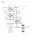
- Fig. 1 is a power transmission system diagram of a travel transmission apparatus according to the invention.
- a travel transmission apparatus 1 illustrated in this diagram changes the speed of power generated by an engine 2 and transmits the power to a left-and-right pair of drive wheels 3 and 3.
- the left-and-right pair of drive wheels 3 and 3 are a left-and-right pair of front wheels of a four wheel vehicle in an example illustrated in this diagram.
- the travel transmission apparatus 1 includes a main shaft 8, a countershaft 9, and a travel gear change mechanism (a gear change mechanism) 11.
- the power of the engine 2 is output to a crankshaft 6, which is an engine output shaft.
- the power is then transmitted from the crankshaft 6 through a main clutch 7 in a manner that allows disconnection to the main shaft 8, which is an input shaft coaxial with the crankshaft 6.
- the countershaft 9 is an output shaft arranged in parallel with the main shaft 8.
- the countershaft 9 is provided with a drive gear 12 that rotates in synchronization (or rotates in combination, to be specific) with the countershaft 9.
- the rotating power of the drive gear 12 is transmitted to a ring gear 13a of a differential 13 and then the power transmitted to the ring gear 13a is transmitted to the right and left drive wheels 3 and 3 through the differential 13.
- the main clutch 7, when connected, allows the power to be transmitted from the crankshaft 6 to the main shaft 8 , whereas, when disconnected, it interrupts the transmission of the power from the crankshaft 6 to the main shaft 8.
- the travel gear change mechanism 11 includes a first input gear 16A and a second input gear 16B provided so as to rotate in synchronization (or rotates in combination, to be specific) with the main shaft 8, a third input gear 16C and a fourth input gear 16D supported through an undepicted bearing or the like on the main shaft 8 in a manner that allows relative rotation (or in a manner that allows idling, to be specific), a fifth input gear 16E and a sixth input gear 16F supported through an undepicted bearing or the like on the main shaft 8 in a manner that allows relative rotation (or in a manner that allows idling, to be specific), a first output gear 17A and a second output gear 17B supported through an undepicted bearing or the like on the countershaft 9 in a manner that allows relative rotation (or in a manner that allows idling, to be specific), a third output gear 17C and a fourth output gear 17D provided so as to rotate in synchronization (or rotates in combination, to be specific) with the countershaft 9,
- the first to sixth input gears 16A, 16B, 16C, 16D, 16E, and 16F are arranged in the order set forth in an axial direction (a shifting direction) of the main shaft 8 toward one side (toward the right in Fig. 1 , which will be referred to as a "high speed side” herein).
- the input gears 16A, 16B, 16C, 16D, 16E, and 16F increase in diameter and the number of teeth as they are located more toward the high speed side.
- the right side in Fig. 1 is the high speed side as described above.
- the first to sixth output gears 17A, 17B, 17C, 17D, 17E, and 17F are arranged in the order set forth in the shifting direction toward the high speed side.
- the output gears 17A, 17B, 17C, 17D, 17E, and 17F decrease in diameter and the number of teeth as they are located more toward the high speed side.
- the first input gear 16A and the first output gear 17A coincide with each other at a position in the shifting direction to be in constant mesh.
- the second input gear 16B and the second output gear 17B coincide with each other at a position in the shifting direction to be in constant mesh.
- the third input gear 16C and the third output gear 17C coincide with each other at a position in the shifting direction to be in constant mesh.
- the fourth input gear 16D and the fourth output gear 17D coincide with each other at a position in the shifting direction to be in constant mesh.
- the fifth input gear 16E and the fifth output gear 17E coincide with each other at a position in the shifting direction to be in constant mesh.
- the sixth input gear 16F and the sixth output gear 17F coincide with each other at a position in the shifting direction to be in constant mesh.
- the travel gear change mechanism 11 is provided with a low-speed-side sleeve 19, a medium-speed-side sleeve 21, and a high-speed-side sleeve 22.
- the low-speed-side sleeve 19 is a synchronous mesh-type clutch arranged on the countershaft 9 between the first output gear 17A and the second output gear 17B.
- the medium-speed-side sleeve 21 is a synchronous mesh-type clutch arranged on the main shaft 8 between the third input gear 16C and the fourth input gear 16D.
- the high-speed-side sleeve 22 is a synchronous mesh-type clutch arranged on the main shaft 8 between the fifth input gear 16E and the sixth input gear 16F.
- the low-speed-side sleeve 19 is configured to be able to slide in an axial direction of the countershaft 9, which is the shifting direction, and rotate in synchronization (or rotate in combination, to be specific) with the countershaft 9.
- the first output gear 17A and the low-speed-side sleeve 19 are synchronized by a synchronizing means 19a provided therebetween to come into mesh with each other.
- a state (a first state) is achieved in which the first output gear 17A, together with the low-speed-side sleeve 19, rotates in synchronization (or rotates in combination, to be specific) with the countershaft 9.
- the second output gear 17B and the low-speed-side sleeve 19 are synchronized by a synchronizing means 19b provided therebetween to come into mesh with each other.
- a state (a second state) is achieved in which the second output gear 17B, together with the low-speed-side sleeve 19, rotates in synchronization (or rotates in combination, to be specific) with the countershaft 9.
- the medium-speed-side sleeve 21 is configured to be able to slide in the axial direction of the main shaft 8, which is the shifting direction, and rotate in synchronization (or rotate in combination, to be specific) with the main shaft 8.
- the third input gear 16C and the medium-speed-side sleeve 21 are synchronized by a synchronizing means 21a provided therebetween to come into mesh with each other.
- a state (a third state) is achieved in which the third input gear 16C, together with the medium-speed-side sleeve 21, rotates in synchronization (or rotates in combination, to be specific) with the main shaft 8.
- the fourth input gear 16D and the medium-speed-side sleeve 21 are synchronized by a synchronizing means 21b provided therebetween to come into mesh with each other.
- a state (a fourth state) is achieved in which the fourth input gear 16D, together with the medium-speed-side sleeve 21, rotates in synchronization (or rotates in combination, to be specific) with the main shaft 8.
- the high-speed-side sleeve 22 is configured to be able to slide in the axial direction of the main shaft 8, which is the shifting direction, and rotate in synchronization (or rotate in combination, to be specific) with the main shaft 8.
- the fifth input gear 16E and the high-speed-side sleeve 22 are synchronized by a synchronizing means 22a provided therebetween to come into mesh with each other.
- a state (a fifth state) is achieved in which the fifth input gear 16E, together with the high-speed-side sleeve 22, rotates in synchronization (or rotates in combination, to be specific) with the main shaft 8.
- the sixth input gear 16F and the high-speed-side sleeve 22 are synchronized by a synchronizing means 22b provided therebetween to come into mesh with each other.
- a state (a sixth state) is achieved in which the sixth input gear 16F, together with the high-speed-side sleeve 22, rotates in synchronization (or rotates in combination, to be specific) with the main shaft 8.
- the rotating speed of the power transmitted from the main shaft 8 to the countershaft 9 is set higher in the order from the first state, the second state, the third state, the fourth state, the fifth state, and then to the sixth state as a function of the numbers of teeth and the diameters of the first to sixth input gears 16A, 16B, 16C, 16D, 16E, and 17F and the first to sixth output gears 17A, 17B, 17C, 17D, 17E, and 17F.
- the travel transmission apparatus 1 is configured to allow for switching of six travel gear ratio in total for forward travel.
- the forward travel power that has undergone the travel gear ratio change in this manner is transmitted to the drive wheels 3 .
- the travel transmission apparatus 1 is also provided with a reverse rotation transmission mechanism, not shown, that transmits a reverse rotating power for reverse travel from the main shaft 8 through the countershaft 9 to the drive wheels 3.
- the travel transmission apparatus 1 is in a neutral state or in a power transmission state.
- the neutral state all the three sleeves 19, 21, and 22 are located in their neutral positions, so that the power is not transmitted to the countershaft 9 (to the drive wheels 3).
- the power transmission state any one of the three sleeves 19, 21, and 22 is operated to the high speed side or to the low speed side to achieve a state in which the power is transmitted, and the remaining two sleeves are located at their neutral positions.
- the main clutch 7 is disconnected before the speed switching to achieve a state in which the power is not transmitted to the main shaft 8. After the speed switching, the main clutch 7 is connected again.
- the three sleeves 19, 21, and 22 are provided with shift members 23, 24, and 26, respectively, for sliding the sleeves 19, 21, and 22 in the shifting direction.
- Fig. 2 is a perspective view of the shift members.
- the shift members 23, 24, and 26 include integrally fork shafts 23a, 24a, and 26a, shift forks 23b, 24b, and 26b, and manipulation plates 23c, 24c, and 26c, respectively.
- the fork shafts 23a, 24a, and 26a are formed in the shifting direction and supported slidably in their respective axial directions by a transmission casing 1a (see Fig. 5 ) that houses the travel gear change mechanism 11.
- the shift forks 23b, 24b, and 26b are provided on the fork shafts 23a, 24a, and 26a, respectively, and are each shaped like an arc when observed from each of the axial directions of the fork shafts 23a, 24a, and 26a so as to engage through the recess/protrusion structure the circumferential surfaces of the sleeves 19, 21, and 22 that are to be manipulated to slide.
- the manipulation plates 23c, 24c, and 26c are provided on the fork shafts 23a, 24a, and 26a, respectively, and protrude outward radially from the fork shafts 23a, 24a, and 26a, respectively.
- Each of the manipulation plates 23c, 24c, and 2 6c has at a radially protruding end (a distal end) thereof an engagement portion 27 having a substantially U shape and recessed toward a proximal end thereof.
- the travel transmission apparatus 1 is provided with a gear switch mechanism 28 (see Figs. 3 to 5 ) to perform selecting operation and shifting operation.
- the selecting operation is to engage with any one of the shift members 23, 24, and 26.
- the shifting operation is to allow the engaged one of the shift members 23, 24, and 26 to slide one of the sleeves 19, 21, and 22 that the engaged one of the shift members 23, 24, and 26 is engaged with in the shifting direction.
- Fig. 3 is a plan view of a configuration of a shift lever.
- Fig. 4 is a partial sectional view for describing a configuration of the gear switch mechanism observed in the shifting direction.
- Fig. 5 is a partial sectional view for describing the configuration of the gear switch mechanism observed from a side orthogonal to the shifting direction.
- a shift lever (a manipulator to change speed) 29 is manipulated to swing.
- the shift lever 29 includes at an upper end a shift knob 29a, which is a grip portion of the shift lever 29, with an intermediate portionof the shift lever 29 penetrating a guide hole 31.
- the guide hole 31 guides the swinging of the shift lever 29.
- manipulation to swing the shift lever 29 side to side is enabled from a fore-and-aft neutral position.
- the shift lever 29 When the shift lever 29 has been swung to the end at one side through the selecting manipulation, the shift lever 29 can be manipulated to swing fore and aft (shifting manipulation) .
- This shifting manipulation achieves low-speed-side shifting manipulation to switch the travel transmission apparatus 1 to any of the first state (the first speed), neutral, or the second state (a second speed) through the low-speed-side sleeve 19 and the low-speed-side shift member 23, which is the shift member engaged with the low-speed-side sleeve 19.
- the shift lever 29 When the shift lever 29 has been swung to a side-to-side neutral position through the selecting manipulation, the shift lever 29 can be manipulated to swing fore and aft (the shifting manipulation).
- This shifting manipulation achieves medium-speed-side shifting manipulation to switch the travel transmission apparatus 1 to any of the third state (a third speed), neutral, or the fourth state (a fourth speed) through the medium-speed-side sleeve 21 and the medium-speed-side shift member 24, which is the shift member engaged with the medium-speed-side sleeve 21.
- the shift lever 29 When the shift lever 29 has been swung to the end at the other side through the selecting manipulation, the shift lever 29 can be manipulated to swing fore and aft (the shifting manipulation).
- This shifting manipulation achieves high-speed-side shifting manipulation to switch the travel transmission apparatus 1 to any of the fifth state (a fifth speed), neutral, or the sixth state (the sixth speed) through the high-speed-side sleeve 22 and the high-speed-side shift member 26, which is the shift member engaged with the high-speed-side sleeve 22.
- a side-to-side swing range of the shift lever 29 for the selecting manipulation is a neutral region N.
- the gear switch mechanism 28 includes a select-and-shift shaft 32, an inner lever 33 , an interlock plate 34 , and a lock ball mechanism 36.
- the select-and-shift shaft 32 which is a horizontal shaft orthogonal to the shifting direction, turns (the shifting operation) about its axis through the selecting manipulation and moves (the selecting operation) in its axial direction (a selecting direction) through the shifting manipulation.
- the inner lever 33 which wraps the select-and-shift shaft 32, moves in the axial direction in combination with the select-and-shift shaft 32 and turns about the axis.
- the interlock plate 34 is disposed so as to hold the inner lever 33 between both sides in the selecting direction.
- the select-and-shift shaft 32 is supported on the transmission casing la so as to be able to turn about its axis and slide in the axial direction of its axis.
- the inner lever 33 includes a tubular portion 33a, a lever portion 33b, and an engagement recess portion 33c.
- the tubular portion 33a wraps the select-and-shift shaft 32.
- the lever portion 33b extends from the tubular portion 33a toward the engagement portions 27 in the manipulation plates 23c, 24c, and 26c of the shift members 23, 24, and 27 (downward to be specific) .
- the engagement recess portion 33c is a recess formed in the tubular portion 33a at a side opposite to the lever portion 33b.
- the interlock plate 34 moves in the axial direction of the select-and-shift shaft 32 in combination with the select-and-shift shaft 32, but its turning about the axis of the select-and-shift shaft 32 is blocked by the lock ball mechanism 36.
- the interlock plate 34 has at its top facing the lock ball mechanism 36 a through hole 36a and at a side opposite thereto a pair of integral lock claws 37 and 38 bent so as to have the lever portion 33b of the inner lever 33 interposed therebetween at both sides in the selecting direction.
- the lock ball mechanism 36 includes a moving member 39, a lock ball 41, and an elastic member 42.
- the moving member 39 penetrates the through hole 36a and is supported on the transmission casing la moveably toward and away from the select-and-shift shaft 32.
- the lock ball 41 is fitted in the moving member 39 at its end facing the select-and-shift shaft 32 (a distal end) and can be also fitted on the engagement recess portion 33c through the recess/protrusion structure.
- the elastic member 42 such as a compression spring, urges the moving member 39 toward the select-and-shift shaft 32.
- the interlock plate 34 and the lock ball mechanism 36 are arranged so that the moving member 39 penetrating the through hole 36a blocks the turning of the interlock plate 34 about the axis of the select-and-shift shaft 32 and that the inner lever 33 is turned to a position at which the engagement recess portion 33c is fitted through the recess/protrusion structure on the lock ball 41 when the travel transmission apparatus 1 is in the neutral state.
- the inner lever 33 is guided to turn (turning operation) to a side at which the engagement recess portion 33c is fitted through the recess/protrusion structure on the lock ball 41 due to an urging force of the elastic member 42 .
- a force which is of a magnitude to overcome the urging force of the elastic member 42 to disengage the fitting of the lock ball 41 on the engagement recess portion 33c through the recess/protrusion structure, in a direction about the axis of the select-and-shift shaft 32.
- the lever portion 33b when the low-speed-side shifting manipulation is enabled through the selecting manipulation, the lever portion 33b is engaged with the engagement portion 27 of the low-speed-side shift member 23, allowing the low-speed-side sleeve 19 to be manipulated to slide in the shifting direction in both ways through swinging of the lever portion 33b in the shifting direction in both ways. Conversely, the moving of the other shift members 24 and 26 in the shifting direction is restricted (or blocked to be specific) by the lock claw 38 being inserted into the engagement portions 27 in the selecting direction.
- the lever portion 33b When the medium-speed-side shifting manipulation is enabled through the selecting manipulation, the lever portion 33b is engaged with the engagement portion 27 of the medium-speed-side shift member 24, allowing the medium-speed-side sleeve 21 to be manipulated to slide in the shifting direction in both ways through the swinging of the lever portion 33b in the shifting direction in both ways . Conversely, the moving of the other shift members 23 and 26 in the shifting direction is restricted (or blocked to be specific) by the lock claws 37 and 38 being inserted into the engagement portions 27 in the selecting direction.
- the lever portion 33b When the high-speed-side shiftingmanipulation is enabled through the selecting manipulation, the lever portion 33b is engaged with the engagement portion 27 of the high-speed-side shift member 26, allowing the high-speed-side sleeve 22 to be manipulated to slide in the shifting direction in both ways through the swinging of the lever portion 33b in the shifting direction in both ways. Conversely, the moving of the other shift members 23 and 24 in the shifting direction is restricted (or blocked to be specific) by the lock claw 37 being inserted into the engagement portions 27 in the selecting direction.
- a neutral detection switch 43 is provided to detect the neutral state of the travel gear change mechanism 11 (see Figs. 6 and 7 ) .
- Fig. 6 is a diagram for describing a configuration of the neutral detection switch
- Fig. 7 is a diagram of a configuration of a main portion of Fig. 6 .
- the travel transmission apparatus 1 is provided with a cam member (cam-like member) 44 and a push-button neutral detection switch 43 including and a detection body 43a.
- the cam member 44 performs the turning operation in conjunction with the gear change operation of the travel gear change mechanism 11 through the gear switch mechanism 28 between the first to sixth speeds .
- the detection body 43a is operated to advance/retreat through contact with the cam member 44.
- the cam member 44 includes integrally a tubular portion 46 and a cam portion 47 (which are formed into one piece in an example illustrated in the figure) .
- the tubularportion46 wraps the select-and-shift shaft 32 to be turned about the axis of the select-and-shift shaft 32 and moved in the axial direction together with the select-and-shift shaft 32.
- the cam portion 47 protrudes radially from the tubular portion 46 toward the transmission casing 1a.
- the select-and-shift shaft 32 serves as a turning shaft for the cam member 44.
- the cam portion 47 is shaped like a plate having a thickness in the shifting direction.
- the cam portion 47 is turned in the shifting direction through the shifting operation.
- the cam portion 47 has a contact edge 48, which is a protruding end (a distal end) in contact with the detection body 43a of the neutral detection switch 43.
- the end at the contact edge 48 has an extended portion 49 elongated in a turning direction of the cam member 44 in both ways. Because of the extended portion 49, the cam member 44 forms substantially a T-shape when observed from the axial direction of the select-and-shift shaft 32, allowing a range of the contact made with the detection body 43a by the cam member 44 during the turning to be extended.
- the moving of the select-and-shift shaft 32 in the axial direction during the selecting operation entails the cam member 44 moving in the selecting direction.
- a thickness of the cam portion 47 is set to prevent the disengagement of the contact with the neutral detection switch 43 during the moving.
- the cam member 44 may be supported to allow sliding relative to the select-and-shift shaft 32 in the axial direction, so that the cam member 44 does not move in the selecting direction during the selecting operation.
- the contact edge 48 has at its middle in the turning direction an advance operation portion 48a, which is a wedge-shaped recess formed toward a turning pivot S of the cam member 44.
- the contact edge 48 also has retreat operation portions 48b, which are together shaped like an arc with the center at the turning pivot S, in areas other than the advance operation portion 48a. Due to the configuration described above, the retreat operation portions 48b are arranged at both sides of the advance operation portion 48a in the turning direction.
- a connection portion 48c between any one of the retreat operation portions 48b and the advance operation portion 48a is rounded to provide a smooth connection therebetween.
- the wedge-shaped bottom of the advance operation portion 48a may also be rounded, although the bottom is shaped to have an obtuse angle in the illustrated example.
- the neutral detection switch 43 is oriented in a radial direction of an arc-like movement track D of the cam member 44 with the detection body 43a facing the cam member 44.
- a switch body 43b of the neutral detection switch 43 is secured to the transmission casing 1a.
- the direction of reciprocating operation of the detection body 43a is directed to the radial direction of the arc-like movement track D.
- the direction of the reciprocating operation is the direction of the advancing/retreating to/from the cam member 44.
- the detection body 43a is shaped like a cylinder extending in the advancing/retreating direction.
- the detection body 43a has an end (a distal end) facing the cam member 44 and shaped like a hemisphere accommodated or substantially accommodated in the wedge-shaped recess of the advance operation portion 48a to be fitted therein. This hemispherical portion is in contact with the cam member 44.
- the advance operation portion 48a is rendered recessed in a wedge shape at the side of the advancing of the detection body 43a.
- the detection body 43a is operated to advance when in contact with the advance operation portion 48a.
- the retreat operation portions 48b are located at the side of the retreating of the detection body 43a.
- the detection body 43a is operated to retreat when in contact with any one of the retreat operation portions 48b.
- the cam member 44 and the neutral detection switch 43 are arranged so that, in the neutral state in which the selecting manipulation is enabled, the hemispherical portion of the detection body 43a achieves a maximum advance to come into contact with the bottom of the advance operation portion 48a, which is a wedge-shaped recess of the cam member 44.
- the cam member 44 and the neutral detection switch 43 are also arranged so that, after the shifting operation out of the neutral state into any other state, the hemispherical portion of the detection body 43a comes into contact with an intermediate portion of the advance operation portion 48a other than the bottom to be operated to retreat partway, or the hemispherical portion of the detection body 43a comes into contact with one of the retreat operation portions 48b to achieve a maximum retreat operation.
- the advance operation of the detection body 43a allows the neutral detection switch 43 to turn ON, whereas the retreat operation of the detection body 4 3a allows the neutral detection switch 43 to turn OFF.
- the neutral detection switch 43 By determining whether the neutral detection switch 43 is ON or OFF, it can be determined whether or not the travel gear change mechanism 11 is in the neutral state.
- Fig. 8 is a characteristic graph of a cam member to which the invention is applied, in comparison with a conventional and publicly known protruding cam member.
- the graph has a comparative example that uses the identical configuration except the cam member with a contact edge shaped to protrude like an arc.
- turning quantities (shift strokes) of the cam members during the shifting operation and moving quantities (switch strokes) of the detection bodies in the advancing/retreating direction are compared between the invention and the comparative example.
- the invention has a detection range, which is a range in which the neutral state of the travel gear change mechanism 11 is detected by the neutral detection switch 43, narrower than that of the comparative example.
- the invention can provide the detection of the neutral state with small variability and high accuracy.
- Fig. 9A is a block diagram of a control unit installed in a four wheel vehicle to which the invention is applied.
- Fig. 9B is a flowchart of processing of the control unit.
- the neutral detection switch 43 and the cam member 44 described above can be used to perform engine start control for idling stop.
- a control unit 51 which includes a microcomputer and the like, is connected at its input side to the neutral detection switch 43, an alternator state detection means 52, and a clutch pedal manipulation detection means 53.
- the alternator state detection means 52 is for detecting a power generation state with the engine 2 driven.
- the clutch pedal manipulation detection means 53 is for detecting connection/disconnection manipulation of a clutch pedal that performs the connection/disconnection manipulation of the main clutch 7.
- the control unit 51 is also connected at its output side to an engine start means 54, which includes a spark plug and the like, for starting the engine 2.
- step S1 the alternator state detection means 52 determines whether or not the alternator is in the power generation state with the engine power. If the alternator is not in the power generation state, it is assumed that the engine 2 is stopped being driven and the flowchart proceeds to step S2. Otherwise, the processing in step S1 is performed again.
- step S2 the neutral detection switch 43 determines whether or not the travel gear change mechanism 11 is in the neutral state. If the travel gear change mechanism 11 is not in the neutral state, starting the engine 2 is likely to cause the power to be transmitted to the drive wheels 3 inadvertently, and thus the flowchart reverts back to step S1. If the travel gear change mechanism 11 is in the neutral state, it is likely that the engine 2 can be started, and the flowchart proceeds to step S3.
- step S3 the clutch pedal manipulation detection means 53 detects the manipulation of the clutch pedal to determine whether or not the main clutch 7 is disconnect so that the engine power is not transmitted to the travel gear change mechanism 11. If the main clutch 7 is disconnected, it is judged that the engine 2 can be started, and the flowchart proceeds to step S4. Otherwise, it is judged that it is not desirable to start the engine 2, and the flowchart reverts back to step S1. In step S4, the engine start means 54 starts the engine 2, which finishes the processing.
- Such engine start control can be performed in a smooth and reliable manner due to the high accuracy of the neutral detection.
Applications Claiming Priority (1)
| Application Number | Priority Date | Filing Date | Title |
|---|---|---|---|
| JP2013155593A JP6231802B2 (ja) | 2013-07-26 | 2013-07-26 | 走行伝動装置 |
Publications (2)
| Publication Number | Publication Date |
|---|---|
| EP2829772A1 true EP2829772A1 (de) | 2015-01-28 |
| EP2829772B1 EP2829772B1 (de) | 2018-11-07 |
Family
ID=51225343
Family Applications (1)
| Application Number | Title | Priority Date | Filing Date |
|---|---|---|---|
| EP14178532.9A Not-in-force EP2829772B1 (de) | 2013-07-26 | 2014-07-25 | Bewegungsübertragungsvorrichtung |
Country Status (2)
| Country | Link |
|---|---|
| EP (1) | EP2829772B1 (de) |
| JP (1) | JP6231802B2 (de) |
Families Citing this family (1)
| Publication number | Priority date | Publication date | Assignee | Title |
|---|---|---|---|---|
| JP7470084B2 (ja) | 2021-09-10 | 2024-04-17 | 株式会社東芝 | 電子回路、電子システム及び駆動方法 |
Citations (4)
| Publication number | Priority date | Publication date | Assignee | Title |
|---|---|---|---|---|
| EP1152174A2 (de) * | 2000-05-05 | 2001-11-07 | Eaton Corporation | Kombination eines Rastmechanismus mit Messfühler für die Leerlaufstellung eines Getriebes |
| EP1350991A1 (de) * | 2002-03-26 | 2003-10-08 | GETRAG FORD Transmissions GmbH | Sensoranordnung zur Bestimmung der Schaltwalzenstellung |
| JP2006138345A (ja) | 2004-11-10 | 2006-06-01 | Mazda Motor Corp | 変速機 |
| FR2904395A1 (fr) * | 2006-07-31 | 2008-02-01 | Peugeot Citroen Automobiles Sa | Procede de determination de l'etat de point mort d'une boite de vitesses de vehicule automobile |
Family Cites Families (3)
| Publication number | Priority date | Publication date | Assignee | Title |
|---|---|---|---|---|
| JPS58191353A (ja) * | 1982-04-30 | 1983-11-08 | Hino Motors Ltd | 自動車用変速装置 |
| JP4004131B2 (ja) * | 1998-02-27 | 2007-11-07 | いすゞ自動車株式会社 | オートクラッチ車両 |
| JP2000088096A (ja) * | 1998-09-17 | 2000-03-28 | Aichi Mach Ind Co Ltd | ニュートラルスイッチの配設構造 |
-
2013
- 2013-07-26 JP JP2013155593A patent/JP6231802B2/ja not_active Expired - Fee Related
-
2014
- 2014-07-25 EP EP14178532.9A patent/EP2829772B1/de not_active Not-in-force
Patent Citations (4)
| Publication number | Priority date | Publication date | Assignee | Title |
|---|---|---|---|---|
| EP1152174A2 (de) * | 2000-05-05 | 2001-11-07 | Eaton Corporation | Kombination eines Rastmechanismus mit Messfühler für die Leerlaufstellung eines Getriebes |
| EP1350991A1 (de) * | 2002-03-26 | 2003-10-08 | GETRAG FORD Transmissions GmbH | Sensoranordnung zur Bestimmung der Schaltwalzenstellung |
| JP2006138345A (ja) | 2004-11-10 | 2006-06-01 | Mazda Motor Corp | 変速機 |
| FR2904395A1 (fr) * | 2006-07-31 | 2008-02-01 | Peugeot Citroen Automobiles Sa | Procede de determination de l'etat de point mort d'une boite de vitesses de vehicule automobile |
Also Published As
| Publication number | Publication date |
|---|---|
| EP2829772B1 (de) | 2018-11-07 |
| JP2015025512A (ja) | 2015-02-05 |
| JP6231802B2 (ja) | 2017-11-15 |
Similar Documents
| Publication | Publication Date | Title |
|---|---|---|
| CN107923529B (zh) | 变速装置和车辆 | |
| EP2042782B1 (de) | Fahrzeuggetriebe | |
| US8042419B2 (en) | Vehicle transmission | |
| EP2966320B1 (de) | Mehrganggetriebe für ein fahrzeug | |
| US10190678B2 (en) | Twin-clutch transmission | |
| RU2395023C2 (ru) | Система управления переключением передач в автоматической трансмиссии | |
| US20170219074A1 (en) | An overrunning transmission device convenient for switching | |
| EP3734113A1 (de) | Vorrichtung zum antrieb eines elektrofahrzeugs und verfahren zu steuerung davon | |
| EP2789878A1 (de) | Automatikgetriebe | |
| CN101660605A (zh) | 车辆变速装置 | |
| RU2395738C2 (ru) | Система управления переключением передач в автоматической трансмиссии | |
| TW201540992A (zh) | 變速控制裝置 | |
| US9976604B2 (en) | Engagement device and automatic transmission | |
| EP2829772B1 (de) | Bewegungsübertragungsvorrichtung | |
| US7775133B2 (en) | Vehicle transmission | |
| CN102996788B (zh) | 双离合器式自动变速器及其变速控制方法 | |
| JP2016191390A (ja) | 車両の変速装置 | |
| US10093319B2 (en) | Variable speed control system | |
| EP3193033B1 (de) | Steuergerät eines fahrzeugs sowie fahrzeug | |
| US11585649B2 (en) | Shift drum angle detecting device for transmission | |
| JP2016191395A (ja) | 車両の変速装置 | |
| CN108713109A (zh) | 双离合式变速器的控制装置及控制方法 | |
| KR20090095768A (ko) | 더블클러치 변속장치 | |
| US10995851B2 (en) | Gear change control device | |
| JP2014114907A (ja) | ラチェット機構及びそれを備えた変速切換装置 |
Legal Events
| Date | Code | Title | Description |
|---|---|---|---|
| 17P | Request for examination filed |
Effective date: 20140725 |
|
| AK | Designated contracting states |
Kind code of ref document: A1 Designated state(s): AL AT BE BG CH CY CZ DE DK EE ES FI FR GB GR HR HU IE IS IT LI LT LU LV MC MK MT NL NO PL PT RO RS SE SI SK SM TR |
|
| AX | Request for extension of the european patent |
Extension state: BA ME |
|
| PUAI | Public reference made under article 153(3) epc to a published international application that has entered the european phase |
Free format text: ORIGINAL CODE: 0009012 |
|
| R17P | Request for examination filed (corrected) |
Effective date: 20150728 |
|
| RBV | Designated contracting states (corrected) |
Designated state(s): AL AT BE BG CH CY CZ DE DK EE ES FI FR GB GR HR HU IE IS IT LI LT LU LV MC MK MT NL NO PL PT RO RS SE SI SK SM TR |
|
| 17Q | First examination report despatched |
Effective date: 20150902 |
|
| REG | Reference to a national code |
Ref country code: DE Ref legal event code: R079 Ref document number: 602014035468 Country of ref document: DE Free format text: PREVIOUS MAIN CLASS: F16H0059700000 Ipc: F16H0059680000 |
|
| GRAP | Despatch of communication of intention to grant a patent |
Free format text: ORIGINAL CODE: EPIDOSNIGR1 |
|
| STAA | Information on the status of an ep patent application or granted ep patent |
Free format text: STATUS: GRANT OF PATENT IS INTENDED |
|
| RIC1 | Information provided on ipc code assigned before grant |
Ipc: F16H 63/30 20060101ALI20180420BHEP Ipc: F16H 59/68 20060101AFI20180420BHEP |
|
| INTG | Intention to grant announced |
Effective date: 20180514 |
|
| GRAS | Grant fee paid |
Free format text: ORIGINAL CODE: EPIDOSNIGR3 |
|
| GRAA | (expected) grant |
Free format text: ORIGINAL CODE: 0009210 |
|
| STAA | Information on the status of an ep patent application or granted ep patent |
Free format text: STATUS: THE PATENT HAS BEEN GRANTED |
|
| AK | Designated contracting states |
Kind code of ref document: B1 Designated state(s): AL AT BE BG CH CY CZ DE DK EE ES FI FR GB GR HR HU IE IS IT LI LT LU LV MC MK MT NL NO PL PT RO RS SE SI SK SM TR |
|
| REG | Reference to a national code |
Ref country code: GB Ref legal event code: FG4D |
|
| REG | Reference to a national code |
Ref country code: CH Ref legal event code: EP Ref country code: AT Ref legal event code: REF Ref document number: 1062429 Country of ref document: AT Kind code of ref document: T Effective date: 20181115 |
|
| REG | Reference to a national code |
Ref country code: IE Ref legal event code: FG4D |
|
| REG | Reference to a national code |
Ref country code: DE Ref legal event code: R096 Ref document number: 602014035468 Country of ref document: DE |
|
| REG | Reference to a national code |
Ref country code: NL Ref legal event code: MP Effective date: 20181107 |
|
| REG | Reference to a national code |
Ref country code: LT Ref legal event code: MG4D |
|
| REG | Reference to a national code |
Ref country code: AT Ref legal event code: MK05 Ref document number: 1062429 Country of ref document: AT Kind code of ref document: T Effective date: 20181107 |
|
| PG25 | Lapsed in a contracting state [announced via postgrant information from national office to epo] |
Ref country code: AT Free format text: LAPSE BECAUSE OF FAILURE TO SUBMIT A TRANSLATION OF THE DESCRIPTION OR TO PAY THE FEE WITHIN THE PRESCRIBED TIME-LIMIT Effective date: 20181107 Ref country code: LT Free format text: LAPSE BECAUSE OF FAILURE TO SUBMIT A TRANSLATION OF THE DESCRIPTION OR TO PAY THE FEE WITHIN THE PRESCRIBED TIME-LIMIT Effective date: 20181107 Ref country code: ES Free format text: LAPSE BECAUSE OF FAILURE TO SUBMIT A TRANSLATION OF THE DESCRIPTION OR TO PAY THE FEE WITHIN THE PRESCRIBED TIME-LIMIT Effective date: 20181107 Ref country code: BG Free format text: LAPSE BECAUSE OF FAILURE TO SUBMIT A TRANSLATION OF THE DESCRIPTION OR TO PAY THE FEE WITHIN THE PRESCRIBED TIME-LIMIT Effective date: 20190207 Ref country code: HR Free format text: LAPSE BECAUSE OF FAILURE TO SUBMIT A TRANSLATION OF THE DESCRIPTION OR TO PAY THE FEE WITHIN THE PRESCRIBED TIME-LIMIT Effective date: 20181107 Ref country code: LV Free format text: LAPSE BECAUSE OF FAILURE TO SUBMIT A TRANSLATION OF THE DESCRIPTION OR TO PAY THE FEE WITHIN THE PRESCRIBED TIME-LIMIT Effective date: 20181107 Ref country code: FI Free format text: LAPSE BECAUSE OF FAILURE TO SUBMIT A TRANSLATION OF THE DESCRIPTION OR TO PAY THE FEE WITHIN THE PRESCRIBED TIME-LIMIT Effective date: 20181107 Ref country code: IS Free format text: LAPSE BECAUSE OF FAILURE TO SUBMIT A TRANSLATION OF THE DESCRIPTION OR TO PAY THE FEE WITHIN THE PRESCRIBED TIME-LIMIT Effective date: 20190307 Ref country code: NO Free format text: LAPSE BECAUSE OF FAILURE TO SUBMIT A TRANSLATION OF THE DESCRIPTION OR TO PAY THE FEE WITHIN THE PRESCRIBED TIME-LIMIT Effective date: 20190207 |
|
| PG25 | Lapsed in a contracting state [announced via postgrant information from national office to epo] |
Ref country code: RS Free format text: LAPSE BECAUSE OF FAILURE TO SUBMIT A TRANSLATION OF THE DESCRIPTION OR TO PAY THE FEE WITHIN THE PRESCRIBED TIME-LIMIT Effective date: 20181107 Ref country code: NL Free format text: LAPSE BECAUSE OF FAILURE TO SUBMIT A TRANSLATION OF THE DESCRIPTION OR TO PAY THE FEE WITHIN THE PRESCRIBED TIME-LIMIT Effective date: 20181107 Ref country code: GR Free format text: LAPSE BECAUSE OF FAILURE TO SUBMIT A TRANSLATION OF THE DESCRIPTION OR TO PAY THE FEE WITHIN THE PRESCRIBED TIME-LIMIT Effective date: 20190208 Ref country code: PT Free format text: LAPSE BECAUSE OF FAILURE TO SUBMIT A TRANSLATION OF THE DESCRIPTION OR TO PAY THE FEE WITHIN THE PRESCRIBED TIME-LIMIT Effective date: 20190307 Ref country code: AL Free format text: LAPSE BECAUSE OF FAILURE TO SUBMIT A TRANSLATION OF THE DESCRIPTION OR TO PAY THE FEE WITHIN THE PRESCRIBED TIME-LIMIT Effective date: 20181107 Ref country code: SE Free format text: LAPSE BECAUSE OF FAILURE TO SUBMIT A TRANSLATION OF THE DESCRIPTION OR TO PAY THE FEE WITHIN THE PRESCRIBED TIME-LIMIT Effective date: 20181107 |
|
| PG25 | Lapsed in a contracting state [announced via postgrant information from national office to epo] |
Ref country code: DK Free format text: LAPSE BECAUSE OF FAILURE TO SUBMIT A TRANSLATION OF THE DESCRIPTION OR TO PAY THE FEE WITHIN THE PRESCRIBED TIME-LIMIT Effective date: 20181107 Ref country code: PL Free format text: LAPSE BECAUSE OF FAILURE TO SUBMIT A TRANSLATION OF THE DESCRIPTION OR TO PAY THE FEE WITHIN THE PRESCRIBED TIME-LIMIT Effective date: 20181107 Ref country code: CZ Free format text: LAPSE BECAUSE OF FAILURE TO SUBMIT A TRANSLATION OF THE DESCRIPTION OR TO PAY THE FEE WITHIN THE PRESCRIBED TIME-LIMIT Effective date: 20181107 Ref country code: IT Free format text: LAPSE BECAUSE OF FAILURE TO SUBMIT A TRANSLATION OF THE DESCRIPTION OR TO PAY THE FEE WITHIN THE PRESCRIBED TIME-LIMIT Effective date: 20181107 |
|
| REG | Reference to a national code |
Ref country code: DE Ref legal event code: R097 Ref document number: 602014035468 Country of ref document: DE |
|
| PG25 | Lapsed in a contracting state [announced via postgrant information from national office to epo] |
Ref country code: SK Free format text: LAPSE BECAUSE OF FAILURE TO SUBMIT A TRANSLATION OF THE DESCRIPTION OR TO PAY THE FEE WITHIN THE PRESCRIBED TIME-LIMIT Effective date: 20181107 Ref country code: SM Free format text: LAPSE BECAUSE OF FAILURE TO SUBMIT A TRANSLATION OF THE DESCRIPTION OR TO PAY THE FEE WITHIN THE PRESCRIBED TIME-LIMIT Effective date: 20181107 Ref country code: EE Free format text: LAPSE BECAUSE OF FAILURE TO SUBMIT A TRANSLATION OF THE DESCRIPTION OR TO PAY THE FEE WITHIN THE PRESCRIBED TIME-LIMIT Effective date: 20181107 Ref country code: RO Free format text: LAPSE BECAUSE OF FAILURE TO SUBMIT A TRANSLATION OF THE DESCRIPTION OR TO PAY THE FEE WITHIN THE PRESCRIBED TIME-LIMIT Effective date: 20181107 |
|
| PGFP | Annual fee paid to national office [announced via postgrant information from national office to epo] |
Ref country code: FR Payment date: 20190619 Year of fee payment: 6 |
|
| PLBE | No opposition filed within time limit |
Free format text: ORIGINAL CODE: 0009261 |
|
| STAA | Information on the status of an ep patent application or granted ep patent |
Free format text: STATUS: NO OPPOSITION FILED WITHIN TIME LIMIT |
|
| 26N | No opposition filed |
Effective date: 20190808 |
|
| PG25 | Lapsed in a contracting state [announced via postgrant information from national office to epo] |
Ref country code: SI Free format text: LAPSE BECAUSE OF FAILURE TO SUBMIT A TRANSLATION OF THE DESCRIPTION OR TO PAY THE FEE WITHIN THE PRESCRIBED TIME-LIMIT Effective date: 20181107 |
|
| PGFP | Annual fee paid to national office [announced via postgrant information from national office to epo] |
Ref country code: DE Payment date: 20190710 Year of fee payment: 6 |
|
| PGFP | Annual fee paid to national office [announced via postgrant information from national office to epo] |
Ref country code: GB Payment date: 20190724 Year of fee payment: 6 |
|
| PG25 | Lapsed in a contracting state [announced via postgrant information from national office to epo] |
Ref country code: MC Free format text: LAPSE BECAUSE OF FAILURE TO SUBMIT A TRANSLATION OF THE DESCRIPTION OR TO PAY THE FEE WITHIN THE PRESCRIBED TIME-LIMIT Effective date: 20181107 |
|
| REG | Reference to a national code |
Ref country code: CH Ref legal event code: PL |
|
| PG25 | Lapsed in a contracting state [announced via postgrant information from national office to epo] |
Ref country code: TR Free format text: LAPSE BECAUSE OF FAILURE TO SUBMIT A TRANSLATION OF THE DESCRIPTION OR TO PAY THE FEE WITHIN THE PRESCRIBED TIME-LIMIT Effective date: 20181107 |
|
| REG | Reference to a national code |
Ref country code: BE Ref legal event code: MM Effective date: 20190731 |
|
| PG25 | Lapsed in a contracting state [announced via postgrant information from national office to epo] |
Ref country code: BE Free format text: LAPSE BECAUSE OF NON-PAYMENT OF DUE FEES Effective date: 20190731 Ref country code: LU Free format text: LAPSE BECAUSE OF NON-PAYMENT OF DUE FEES Effective date: 20190725 Ref country code: CH Free format text: LAPSE BECAUSE OF NON-PAYMENT OF DUE FEES Effective date: 20190731 Ref country code: LI Free format text: LAPSE BECAUSE OF NON-PAYMENT OF DUE FEES Effective date: 20190731 |
|
| PG25 | Lapsed in a contracting state [announced via postgrant information from national office to epo] |
Ref country code: IE Free format text: LAPSE BECAUSE OF NON-PAYMENT OF DUE FEES Effective date: 20190725 |
|
| REG | Reference to a national code |
Ref country code: DE Ref legal event code: R119 Ref document number: 602014035468 Country of ref document: DE |
|
| GBPC | Gb: european patent ceased through non-payment of renewal fee |
Effective date: 20200725 |
|
| PG25 | Lapsed in a contracting state [announced via postgrant information from national office to epo] |
Ref country code: GB Free format text: LAPSE BECAUSE OF NON-PAYMENT OF DUE FEES Effective date: 20200725 Ref country code: FR Free format text: LAPSE BECAUSE OF NON-PAYMENT OF DUE FEES Effective date: 20200731 |
|
| PG25 | Lapsed in a contracting state [announced via postgrant information from national office to epo] |
Ref country code: DE Free format text: LAPSE BECAUSE OF NON-PAYMENT OF DUE FEES Effective date: 20210202 Ref country code: CY Free format text: LAPSE BECAUSE OF FAILURE TO SUBMIT A TRANSLATION OF THE DESCRIPTION OR TO PAY THE FEE WITHIN THE PRESCRIBED TIME-LIMIT Effective date: 20181107 |
|
| PG25 | Lapsed in a contracting state [announced via postgrant information from national office to epo] |
Ref country code: HU Free format text: LAPSE BECAUSE OF FAILURE TO SUBMIT A TRANSLATION OF THE DESCRIPTION OR TO PAY THE FEE WITHIN THE PRESCRIBED TIME-LIMIT; INVALID AB INITIO Effective date: 20140725 Ref country code: MT Free format text: LAPSE BECAUSE OF FAILURE TO SUBMIT A TRANSLATION OF THE DESCRIPTION OR TO PAY THE FEE WITHIN THE PRESCRIBED TIME-LIMIT Effective date: 20181107 |
|
| PG25 | Lapsed in a contracting state [announced via postgrant information from national office to epo] |
Ref country code: MK Free format text: LAPSE BECAUSE OF FAILURE TO SUBMIT A TRANSLATION OF THE DESCRIPTION OR TO PAY THE FEE WITHIN THE PRESCRIBED TIME-LIMIT Effective date: 20181107 |