EP2829725B1 - Power supply system - Google Patents
Power supply system Download PDFInfo
- Publication number
- EP2829725B1 EP2829725B1 EP12872239.4A EP12872239A EP2829725B1 EP 2829725 B1 EP2829725 B1 EP 2829725B1 EP 12872239 A EP12872239 A EP 12872239A EP 2829725 B1 EP2829725 B1 EP 2829725B1
- Authority
- EP
- European Patent Office
- Prior art keywords
- power
- running
- carrier
- wind
- rail
- Prior art date
- Legal status (The legal status is an assumption and is not a legal conclusion. Google has not performed a legal analysis and makes no representation as to the accuracy of the status listed.)
- Not-in-force
Links
- 230000007246 mechanism Effects 0.000 claims description 43
- 238000010248 power generation Methods 0.000 claims description 18
- 230000005484 gravity Effects 0.000 claims description 4
- 238000005381 potential energy Methods 0.000 description 18
- 230000000694 effects Effects 0.000 description 6
- 230000008859 change Effects 0.000 description 4
- 238000000034 method Methods 0.000 description 3
- 238000006243 chemical reaction Methods 0.000 description 2
- 238000009434 installation Methods 0.000 description 2
- 230000001172 regenerating effect Effects 0.000 description 2
- 230000001174 ascending effect Effects 0.000 description 1
- 230000008901 benefit Effects 0.000 description 1
- 230000003247 decreasing effect Effects 0.000 description 1
- 230000001419 dependent effect Effects 0.000 description 1
- 238000010586 diagram Methods 0.000 description 1
- 230000005611 electricity Effects 0.000 description 1
- 239000000446 fuel Substances 0.000 description 1
- 230000006872 improvement Effects 0.000 description 1
- 239000007788 liquid Substances 0.000 description 1
- 238000004519 manufacturing process Methods 0.000 description 1
- 230000004048 modification Effects 0.000 description 1
- 238000012986 modification Methods 0.000 description 1
- 239000002994 raw material Substances 0.000 description 1
- 230000008929 regeneration Effects 0.000 description 1
- 238000011069 regeneration method Methods 0.000 description 1
Images


Classifications
-
- H—ELECTRICITY
- H02—GENERATION; CONVERSION OR DISTRIBUTION OF ELECTRIC POWER
- H02K—DYNAMO-ELECTRIC MACHINES
- H02K7/00—Arrangements for handling mechanical energy structurally associated with dynamo-electric machines, e.g. structural association with mechanical driving motors or auxiliary dynamo-electric machines
- H02K7/18—Structural association of electric generators with mechanical driving motors, e.g. with turbines
- H02K7/1807—Rotary generators
- H02K7/1846—Rotary generators structurally associated with wheels or associated parts
-
- F—MECHANICAL ENGINEERING; LIGHTING; HEATING; WEAPONS; BLASTING
- F03—MACHINES OR ENGINES FOR LIQUIDS; WIND, SPRING, OR WEIGHT MOTORS; PRODUCING MECHANICAL POWER OR A REACTIVE PROPULSIVE THRUST, NOT OTHERWISE PROVIDED FOR
- F03D—WIND MOTORS
- F03D9/00—Adaptations of wind motors for special use; Combinations of wind motors with apparatus driven thereby; Wind motors specially adapted for installation in particular locations
-
- A—HUMAN NECESSITIES
- A63—SPORTS; GAMES; AMUSEMENTS
- A63G—MERRY-GO-ROUNDS; SWINGS; ROCKING-HORSES; CHUTES; SWITCHBACKS; SIMILAR DEVICES FOR PUBLIC AMUSEMENT
- A63G7/00—Up-and-down hill tracks; Switchbacks
-
- F—MECHANICAL ENGINEERING; LIGHTING; HEATING; WEAPONS; BLASTING
- F03—MACHINES OR ENGINES FOR LIQUIDS; WIND, SPRING, OR WEIGHT MOTORS; PRODUCING MECHANICAL POWER OR A REACTIVE PROPULSIVE THRUST, NOT OTHERWISE PROVIDED FOR
- F03D—WIND MOTORS
- F03D1/00—Wind motors with rotation axis substantially parallel to the air flow entering the rotor
- F03D1/04—Wind motors with rotation axis substantially parallel to the air flow entering the rotor having stationary wind-guiding means, e.g. with shrouds or channels
-
- F—MECHANICAL ENGINEERING; LIGHTING; HEATING; WEAPONS; BLASTING
- F03—MACHINES OR ENGINES FOR LIQUIDS; WIND, SPRING, OR WEIGHT MOTORS; PRODUCING MECHANICAL POWER OR A REACTIVE PROPULSIVE THRUST, NOT OTHERWISE PROVIDED FOR
- F03D—WIND MOTORS
- F03D5/00—Other wind motors
- F03D5/04—Other wind motors the wind-engaging parts being attached to carriages running on tracks or the like
-
- F—MECHANICAL ENGINEERING; LIGHTING; HEATING; WEAPONS; BLASTING
- F03—MACHINES OR ENGINES FOR LIQUIDS; WIND, SPRING, OR WEIGHT MOTORS; PRODUCING MECHANICAL POWER OR A REACTIVE PROPULSIVE THRUST, NOT OTHERWISE PROVIDED FOR
- F03D—WIND MOTORS
- F03D9/00—Adaptations of wind motors for special use; Combinations of wind motors with apparatus driven thereby; Wind motors specially adapted for installation in particular locations
- F03D9/20—Wind motors characterised by the driven apparatus
- F03D9/25—Wind motors characterised by the driven apparatus the apparatus being an electrical generator
-
- F—MECHANICAL ENGINEERING; LIGHTING; HEATING; WEAPONS; BLASTING
- F03—MACHINES OR ENGINES FOR LIQUIDS; WIND, SPRING, OR WEIGHT MOTORS; PRODUCING MECHANICAL POWER OR A REACTIVE PROPULSIVE THRUST, NOT OTHERWISE PROVIDED FOR
- F03D—WIND MOTORS
- F03D9/00—Adaptations of wind motors for special use; Combinations of wind motors with apparatus driven thereby; Wind motors specially adapted for installation in particular locations
- F03D9/30—Wind motors specially adapted for installation in particular locations
- F03D9/32—Wind motors specially adapted for installation in particular locations on moving objects, e.g. vehicles
-
- F—MECHANICAL ENGINEERING; LIGHTING; HEATING; WEAPONS; BLASTING
- F03—MACHINES OR ENGINES FOR LIQUIDS; WIND, SPRING, OR WEIGHT MOTORS; PRODUCING MECHANICAL POWER OR A REACTIVE PROPULSIVE THRUST, NOT OTHERWISE PROVIDED FOR
- F03G—SPRING, WEIGHT, INERTIA OR LIKE MOTORS; MECHANICAL-POWER PRODUCING DEVICES OR MECHANISMS, NOT OTHERWISE PROVIDED FOR OR USING ENERGY SOURCES NOT OTHERWISE PROVIDED FOR
- F03G3/00—Other motors, e.g. gravity or inertia motors
-
- F—MECHANICAL ENGINEERING; LIGHTING; HEATING; WEAPONS; BLASTING
- F03—MACHINES OR ENGINES FOR LIQUIDS; WIND, SPRING, OR WEIGHT MOTORS; PRODUCING MECHANICAL POWER OR A REACTIVE PROPULSIVE THRUST, NOT OTHERWISE PROVIDED FOR
- F03G—SPRING, WEIGHT, INERTIA OR LIKE MOTORS; MECHANICAL-POWER PRODUCING DEVICES OR MECHANISMS, NOT OTHERWISE PROVIDED FOR OR USING ENERGY SOURCES NOT OTHERWISE PROVIDED FOR
- F03G7/00—Mechanical-power-producing mechanisms, not otherwise provided for or using energy sources not otherwise provided for
- F03G7/10—Alleged perpetua mobilia
- F03G7/104—Alleged perpetua mobilia continuously converting gravity into usable power
-
- F—MECHANICAL ENGINEERING; LIGHTING; HEATING; WEAPONS; BLASTING
- F03—MACHINES OR ENGINES FOR LIQUIDS; WIND, SPRING, OR WEIGHT MOTORS; PRODUCING MECHANICAL POWER OR A REACTIVE PROPULSIVE THRUST, NOT OTHERWISE PROVIDED FOR
- F03D—WIND MOTORS
- F03D9/00—Adaptations of wind motors for special use; Combinations of wind motors with apparatus driven thereby; Wind motors specially adapted for installation in particular locations
- F03D9/10—Combinations of wind motors with apparatus storing energy
- F03D9/11—Combinations of wind motors with apparatus storing energy storing electrical energy
-
- F—MECHANICAL ENGINEERING; LIGHTING; HEATING; WEAPONS; BLASTING
- F05—INDEXING SCHEMES RELATING TO ENGINES OR PUMPS IN VARIOUS SUBCLASSES OF CLASSES F01-F04
- F05B—INDEXING SCHEME RELATING TO WIND, SPRING, WEIGHT, INERTIA OR LIKE MOTORS, TO MACHINES OR ENGINES FOR LIQUIDS COVERED BY SUBCLASSES F03B, F03D AND F03G
- F05B2240/00—Components
- F05B2240/90—Mounting on supporting structures or systems
- F05B2240/93—Mounting on supporting structures or systems on a structure floating on a liquid surface
- F05B2240/931—Mounting on supporting structures or systems on a structure floating on a liquid surface which is a vehicle
-
- H—ELECTRICITY
- H02—GENERATION; CONVERSION OR DISTRIBUTION OF ELECTRIC POWER
- H02K—DYNAMO-ELECTRIC MACHINES
- H02K53/00—Alleged dynamo-electric perpetua mobilia
-
- Y—GENERAL TAGGING OF NEW TECHNOLOGICAL DEVELOPMENTS; GENERAL TAGGING OF CROSS-SECTIONAL TECHNOLOGIES SPANNING OVER SEVERAL SECTIONS OF THE IPC; TECHNICAL SUBJECTS COVERED BY FORMER USPC CROSS-REFERENCE ART COLLECTIONS [XRACs] AND DIGESTS
- Y02—TECHNOLOGIES OR APPLICATIONS FOR MITIGATION OR ADAPTATION AGAINST CLIMATE CHANGE
- Y02B—CLIMATE CHANGE MITIGATION TECHNOLOGIES RELATED TO BUILDINGS, e.g. HOUSING, HOUSE APPLIANCES OR RELATED END-USER APPLICATIONS
- Y02B10/00—Integration of renewable energy sources in buildings
- Y02B10/30—Wind power
-
- Y—GENERAL TAGGING OF NEW TECHNOLOGICAL DEVELOPMENTS; GENERAL TAGGING OF CROSS-SECTIONAL TECHNOLOGIES SPANNING OVER SEVERAL SECTIONS OF THE IPC; TECHNICAL SUBJECTS COVERED BY FORMER USPC CROSS-REFERENCE ART COLLECTIONS [XRACs] AND DIGESTS
- Y02—TECHNOLOGIES OR APPLICATIONS FOR MITIGATION OR ADAPTATION AGAINST CLIMATE CHANGE
- Y02E—REDUCTION OF GREENHOUSE GAS [GHG] EMISSIONS, RELATED TO ENERGY GENERATION, TRANSMISSION OR DISTRIBUTION
- Y02E10/00—Energy generation through renewable energy sources
- Y02E10/70—Wind energy
- Y02E10/72—Wind turbines with rotation axis in wind direction
-
- Y—GENERAL TAGGING OF NEW TECHNOLOGICAL DEVELOPMENTS; GENERAL TAGGING OF CROSS-SECTIONAL TECHNOLOGIES SPANNING OVER SEVERAL SECTIONS OF THE IPC; TECHNICAL SUBJECTS COVERED BY FORMER USPC CROSS-REFERENCE ART COLLECTIONS [XRACs] AND DIGESTS
- Y02—TECHNOLOGIES OR APPLICATIONS FOR MITIGATION OR ADAPTATION AGAINST CLIMATE CHANGE
- Y02P—CLIMATE CHANGE MITIGATION TECHNOLOGIES IN THE PRODUCTION OR PROCESSING OF GOODS
- Y02P70/00—Climate change mitigation technologies in the production process for final industrial or consumer products
- Y02P70/50—Manufacturing or production processes characterised by the final manufactured product
-
- Y—GENERAL TAGGING OF NEW TECHNOLOGICAL DEVELOPMENTS; GENERAL TAGGING OF CROSS-SECTIONAL TECHNOLOGIES SPANNING OVER SEVERAL SECTIONS OF THE IPC; TECHNICAL SUBJECTS COVERED BY FORMER USPC CROSS-REFERENCE ART COLLECTIONS [XRACs] AND DIGESTS
- Y02—TECHNOLOGIES OR APPLICATIONS FOR MITIGATION OR ADAPTATION AGAINST CLIMATE CHANGE
- Y02T—CLIMATE CHANGE MITIGATION TECHNOLOGIES RELATED TO TRANSPORTATION
- Y02T70/00—Maritime or waterways transport
- Y02T70/50—Measures to reduce greenhouse gas emissions related to the propulsion system
- Y02T70/5218—Less carbon-intensive fuels, e.g. natural gas, biofuels
- Y02T70/5236—Renewable or hybrid-electric solutions
Definitions
- the present invention relates to a power supply system for generating and supplying electric power by using potential energy.
- Prior art document GB 2 037 507 A discloses an apparatus for controlling the regenerative braking of a transit vehicle by sensing the operation of the power source third rail for that transit vehicle for the purpose of preventing regeneration of power by a moving vehicle into that power source rail when it has been determined that the power source third rail is not receptive during the regenerative braking effort of that vehicle.
- a wind power generator is configured to rotate a wind mill by wind force and generate electric power by a power generator connected with the wind mill.
- the wind power generator has a problem in that stable electric power cannot be obtained due to output electric power that depends on wind force.
- Patent Literature 1 a wind power generator that utilizes a head wind generated during running of a vehicle or a ship, or navigation
- Patent Literature 2 a wind power generator that utilizes running wind similarly generated during running of a vehicle
- Patent Literature 3 an attempt has been performed to avoid an unnecessary wind pressure by allowing part of generated running wind to escape
- a problem to be solved by the present invention is to increase the number of variations of local supply and local consumption of energy.
- a system is new or existing, in particular in the case of the existing system, if the minimal change in the system allows the system to generate electric power, it can contribute local supply and local consumption of energy. This is the original way of thinking of the inventors.
- a powerless carrier like a roller coaster has proper potential energy when it is located at a high place. In order to bring the roller coaster to the high place (to obtain potential energy), it is a fact that proper energy (e.g., electricity) is used.
- proper energy e.g., electricity
- running collectively referred to "running"
- a power supply system includes: a running rail having at least one low place and at least one high place located at a level higher than the low place in a gravity direction (or each may be two or more places); a powerless carrier (hereinafter, simply referred to as a carrier) placed on the running rail; transporters A and B for transporting the carrier to the high place: a wind power generating mechanism with an impeller, the mechanism being provided on the carrier; and a power output terminal provided on the wind power generating mechanism, wherein electric power generated by rotation of the impeller directly or indirectly caused by running wind generated by running of the carrier is allowed to be taken out from the power output end.
- a powerless carrier hereinafter, simply referred to as a carrier
- the low place and high place on the running rail are relative to each other.
- a place at a level higher than a certain low place is defined as a high place.
- this high place will be defined as a low place if there is another high place higher than such a high place.
- the impeller may be in the inside of the carrier or may be on the outside thereof.
- the number, installation direction, and angle of impellers, the number of wheels, the shape of a chassis, the shape of a body, and the number of rails can be flexibly determined.
- the transporter A can transport the carrier to the high place.
- the carrier at the high place acquires potential energy relative to the low place. If the carrier is released here, the carrier runs on the running rail toward the low place while converting the potential energy into kinetic energy.
- the carrier receives a resistance of the running wind when running.
- the running wind rotates the impeller. Rotation of the impeller drives the wind power generating mechanism to generate electric power.
- the electric power generated from the wind power generating mechanism can be taken out from the power output terminal.
- the electric power output from the power output terminal may be charged into a battery charger or may be supplied to the outside via the rail or the like.
- the power supply system according to the first aspect (hereinafter, appropriately referred to as a system of the first aspect) is configured such that the power output terminal is electrically connected with the running rail or a power-feeding rail (third rail) or an overhead power line arranged in parallel with the running rail and is able to take electric power from the running rail or the power-feeding rail. Since the battery charger is mounted on the carrier, the electrode of the battery charger may be connected in parallel with the running rail or the power-feeding rail.
- a power supply system is the system of the first aspect further including: a power-generation air passage having a running air intake port for allowing running wind to be incorporated into the wind power generating mechanism and a route outlet port for allowing the running wind incorporated from the running air intake port to be discharged to an outside of a vehicle; and the impeller is arranged in the power-generation air passage, and is configured to be rotated by receiving running wind incorporated from the running air intake port.
- the carrier is compactible because the power-generation air passage and the impeller are present in the inside of the carrier in addition to the operation and effects of the system described in the first aspect.
- the running wind can be centralized on the power-generation air passage.
- the energy of the running wind can be effectively utilized.
- concentrating the running wind causes an increase in wind velocity thereof, and, proportionately thereto, the impeller is allowed to rotate quickly, contributing to effective use of energy.
- a power supply system (hereinafter, appropriately referred to as a system of the third aspect) is the system of any one of the first and second aspects, wherein the powerless carrier is placed on the running rail via a plurality of wheels, at least one wheel (or the number of wheels may be two or more) among the wheels being connected to a wheel power generating mechanism to allow the wheel power generating mechanism to generate electric power, and the wheel power generating mechanism is configured to take the generated electric power from a power output terminal thereof.
- any one of the first and second aspects and in addition to electric power supply from the wind power generating mechanism in addition to operation and effects of the system any one of the first and second aspects and in addition to electric power supply from the wind power generating mechanism, the electric power supply from the wheel power generating mechanism becomes possible.
- a power supply system (hereinafter, appropriately referred to as a system of the fourth aspect) is the system of any one of the first to third aspects, wherein the powerless carrier is a roller coaster (a jet coaster).
- an advantage is gained in that the existing infrastructure can be used.
- a power generating system can be built directly utilizing the existing infrastructure by providing the wheel of the roller coaster with the wind power generating mechanism or the like described so far.
- the expense for improvement of a vehicle or manufacture of new one flexible use of an existing part such as a running rail can be sufficient without modification. It is therefore very economical.
- a power supply system includes: a running rail disposed at each of at least one low place and at least high place located at a level higher than the low place in a gravity direction; a powerless carrier placed on the running rail via wheels so as to be run on the running rail; transporters A and B for transporting the carrier to the high place; a power generator rotatably connected to the wheel, and a power output terminal provided in the power generator, wherein the power generator is rotated by rotation of the wheel to take out electric power from the power output end.
- the carrier is transported to the high place by the transporter A.
- the carrier at the high place acquires potential energy relative to the low place. If the carrier is released here, the carrier runs on the running rail toward the low place while converting the potential energy into kinetic energy.
- the power generator is driven by the wheel to generate electric power.
- the electric power generated by the power generator can be taken out from the power output terminal.
- the electric power taken out from the power output terminal may be charged into the battery charger or may be supplied to the outside via the rail or the like.
- a method for supplying electric power according to a sixth aspect including: generating electric power by running wind produced by running an impeller on a rail of a powerless carrier, the impeller being provided in an impeller-equipped wind power generating mechanism mounted on a powerless carrier running by conversion of given potential energy into kinetic energy.
- the carrier located at the high place and provided with the potential energy runs on the rail toward the low place while converting the potential energy into the kinetic energy.
- the carrier receives a resistance of the running wind when running.
- the running wind rotates the impeller.
- Rotation of the impeller drives the wind power generating mechanism to generate electric power.
- the electric power generated from the wind power generating mechanism can be taken out from the power output terminal.
- the electric power output from the power output terminal may be charged into a battery charger or may be supplied to the outside via the rail or the like.
- the present invention it is possible to increase the number of variations of local supply and local consumption of energy.
- the minimal change in the system allows the system to generate electric power to contribute local supply and local consumption of energy.
- a power supply system 1 (hereinafter, appropriately referred to as a system 1) includes a running rail 3 or a running rail 6, a powerless carrier 5, a transporter A51, a transporter B7, an impeller 9, a wind power generating mechanism 11, a power output terminal 13, a wheel power generating mechanism 11a, and a power output terminal 13a. Then, the system 1 incudes a battery charger 15 in the case that electric power cannot be supplied from the running rail.
- a power supply system 1 hereinafter, appropriately referred to as a system 1
- the system 1 incudes a battery charger 15 in the case that electric power cannot be supplied from the running rail.
- these are individually described.
- the running rail 3 or the running rail 6 are formed of two parallel rails and built on an orbit 2.
- the basic type is a two-parallel-rail system on the bottom of the carrier 5, which is comparatively easily balanced and sufficiently simple in structure. Alternatively, if required, it is unavoidably built so as to engage with wheels provided at predetermined positions of the left and right sides or roof portion of the carrier 5.
- each of the running rail 3 and the running rail 6 generically represents two rails on the bottom.
- the running rail 3 or the running rail 6 when simply representing the running rail 3 or the running rail 6 (hereinafter, appropriately abbreviated as a rail), unless otherwise specified, it includes an orbit 2 on which the rail 3 or the rail 6 is built.
- the orbit 2 illustrated in FIGS. 1 , 2 , and 6 is represented in reduced size compared with the size of the carrier 5. This is because of illustrating them to fit on the size of paper.
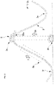
- a figure-of-eight rail 3 has at least one low place and at least one high place located at a level higher than the low place in a gravity direction between its starting and end points. Specifically, as illustrated in FIG. 1 , it is in the shape of a figure of eight in a planar view and has a difference in height as illustrated in FIG. 2 . That is, it descends to the lowest place 3f after repeating descent and ascent from the highest place 3a to the intermediate places 3e, 3b, 3e, 3c, 3e, and 3d, followed by successively extending from the lowest place 3f to the transportation starting point 3g. It further successively extends from the transportation starting point 3g to the highest place serving as a transportation end point.
- reference numeral 4 in FIG 3 denotes a power-feeding rail (indicated by a two dot chain line) constructed in parallel with the rail 3 (alternatively, it may extend along the outside of the rail 3).
- a first one of a plurality of carries 5 transported to the highest place 3a by the transporter A51 is able to run a specified lane and then sequentially move to the adjacent lane at a certain position by switching a switching point, which is used for changing the traveling direction of a train or the like. Accordingly, the transporter A51 may be provided for at least one lane.
- FIG. 6 There is also included a rail 6 along which the carrier 5, which is transported by the transporter A51 and placed in a state of being positioned at, for example, the peak (i.e., the highest place 6a) of a big screw placed upside down, runs down from the highest place 6a to the ground as the bottom along the threads of the screw while passing through points 6b, 6c, and 6d as if the carrier 5 progressively form a larger arc.
- the arc serving as an orbit becomes smaller and the speed of the carrier 5 is lowered.
- the carrier arrives at the center point 6g serving as a transportation-starting point of the transporter A51.
- the carrier 5 is transported to the highest place 6a again by the transporter A51 and then repeats its running.
- the switching point 8 allows an increase in the number of lanes. If the rail 6 is employed, there is no need of the transporter B7. For convenience, the following description is based on the rail 3.
- the transporter B7 is a device for allowing the carrier 5 located at the transportation-starting point 3g to be released to a higher place, the highest position 3a.
- the transporter B7 includes a conveyor belt driven with a battery charger or the like charged by the preceding day.
- the transporter B7 may be any of other systems.
- the wheels of the carrier 5 running on the rail 3 continue rotating while being transported by the transporter B7.
- the carrier 5 transported to the highest place 3a by the transporter B7 obtains potential energy against the low position 3e.
- the transporter B7 is configured to release the carrier 5 at the highest position 3a.
- the released carrier 5 runs on the rail 3 while converting its potential energy into kinetic energy.
- the powerless carrier 5 (hereinafter, simply referred to as a carrier 5) includes a chassis section 21 and a body section 25, which are provided as base members thereof.
- the carrier 5 does not carry any power source for running.
- kinetic energy converted from potential energy serves as energy at the time of power generation.
- the chassis member 21 is basically constructed of a head chassis section 21a and a successive chassis section 21b that follows the head chassis section 21 a. Two or more successive chassis sections 21b may be provided even though only necessary is at least one.
- the number of the successive chassis sections is three, including a successive chassis 21 b on which a wind power generating mechanism is mounted and successive chassis sections 21c to 21 d on which a wheel power generating mechanism is mounted.
- the wind power generating mechanism is only connected or the wheel power generating mechanism is only connected.
- the head section is formed in a streamline shape with a small air resistance.
- the back end of the head chassis section 21a in the travelling direction is connected to the front end of the successive chassis section 21b in the same direction via a joint 22.
- the joint 22 has a joint structure that allows, when the carrier 5 vertically or horizontally changes its travelling direction, the successive chassis section 21b to follow a change in travelling direction of the carrier 5 with respect to the head chassis section 21a.
- the above joints 22 are also used in connection between the successive chassis 21b and the successive chassis 21c and connection between the successive chassis 21c and the successive chassis 21d.
- a plurality of wheels 23 is attached to the both sides of each of the head chassis section 21a and the successive chassis sections 21b to 21 d so that these wheels can rotate on the rail 3.
- the body section 25 includes a head body part 25a and successive body parts 25b to 25d.
- the head body part 25a corresponds to the head chassis section 21a
- the successive body parts 25b to 25d correspond to the successive chassis sections 21b to 21d, respectively.
- the body parts are connected to each other via an accordion structure 26.
- the connection with the accordion structure 26 is provided so as to be allowed to follow a vertical or horizontal change in travelling direction by flexible elasticity in a manner similar to the joint 22, and so as to block a leakage of air incorporated into the body to the outside as far as possible by its airtightness.
- a wing or weight, yaw control rotary impeller, or the like for obtaining down force may be provided on the inside or outside of the body if required.
- each vehicle has four wheels. However, the number of wheels per vehicle is not limited to four.
- a wind power generating mechanism (hereinafter, referred to as a power generating mechanism 11) is illustrated in FIGS. 3 and 4 .
- the power generating mechanism 11 is mounted on each of the head chassis section 21a and the successive chassis section 21b and is configured to be able to generate electric power by running wind w (see FIG. 4 ) caused by running of the carrier 5.
- the power generating mechanism 11 mainly includes: a cannonball-shaped head section 27 mounted on the head chassis 21 a, an impeller 9 and a power generator 12 mounted on the successive chassis section 21 b, and a power-generation air passage 29 surrounded by the chassis section 21 and the body section 25. First, the power-generation air passage 29 will be illustrated.
- a running air intake port 31 is formed as a starting point and opened at the tip of a head body part 25a in a travelling direction and the back end of the successive body part 25d is formed as an end point communicated with the starting point via the successive body parts 25b and 25c.
- the running wind w incorporated from the running air intake port 31 passes through the power-generation air passage 29 and is then discharged from a route outlet port 33.
- an impeller 9 is arranged so that it can be rotated by efficiently receiving the running wind w.
- An output axis of the impeller 9 is attached to the rotor of the power generator 12 to rotate integrally with the rotor.
- the combination of these structural components allow the rotor of the power generator 12 (the rotor is located in the inside of the power generator 12) to rotate by rotation of the impeller 9 so that generated electric power can be taken out from the power output terminal 13 of the power generator 12.
- the installation direction, angle, and the like of the impeller can be flexibly defined.
- a wheel power generating mechanism 11a is mounted on each of the successive chassis sections 21c and 21d.
- the wheel power generating mechanism 11a includes a power generator 12a, a wheel 23, and a gearbox 24 disposed between the power generating mechanism 12a and the wheel 23. That is, the wheel 23 is rotationally connected to the rotor of the power generator 12a (the rotor is not shown because of being inside the power generator 12a). The rotation of the wheel 23 running on the rail 3 causes the power generator 12a to generate electric power. The electric power generated by the power generator 12a can be taken out from the power output terminal 13a.
- the battery charger 15 can be removably mounted on each of the successive chassis sections 21c and 21d.
- the electric power generated from the power generator 12 and the electric power generated from the power generator 12a can be respectively charged into the battery charger 15.
- the carrier 5 located at the highest place 3a illustrated in FIG. 1 is released from restriction with the transporter A51, the carrier 5 runs on the rail 3 toward the lowest place 3f via the intermediate points 3b to 3d while converting its potential energy into kinetic energy.
- the carrier 5 runs upward and reaches to the transportation starting point 3g while newly obtaining potential energy.
- the carrier 5 is transported by the transporter B7 to the highest place 3e. Consequently, the run of the carrier 5 is looped back to the start. If required, the same run is repeated. In this embodiment, descent and ascent are respectively repeated four times, but may be performed in other cycles.
- the running wind w is incorporated into the power-generation air passage 29 of the carrier 5.
- the incorporated running wind w rotates the impeller 9.
- the rotation of the impeller 9 causes the power generator 12 to generate electric power.
- the generated electric power is charged into the battery charger 15 via the power output terminal 13 or supplied to the outside via the power-feeding rail 4 or the like.
- the rotation of the wheel 23 accompanying the run of the carrier 5 causes the power generator 12a to generate electric power.
- the generated electric power is charged or supplied to the outside via the power output terminal 13.
- the transporter A51 generally includes a large diameter tank 53, a small diameter tank 55, an up/down arm 59, a connection tank 57 connecting between the large diameter tank 53 and the small diameter tank 55, and is filled with oil or the like.
- the up/down arm 59 is able to expand and contract (up and down) with respect to the small diameter tank 55 by means of oil pressure or the like.
- a large diameter plate 53a floats on the liquid surface of the large diameter tank 53.
- a part of small diameter plate 55a and running rail 3 (orbit) (this is called 3h) are attached to the upper bed of up/down arm 59.
- the small diameter plate 55a is made larger than the bases area of the small diameter tank so that it may not go into the ground more than needed.
- the large diameter plate 53a is configured to allow several vehicles to be parked thereon and the weight thereof can be adjusted by parking and retrieving the vehicles.
- the operation of the transporter A51 is described.
- the steady state of the transporter A51 is a state where the carrier 5 is at the same level as the ground as illustrated in FIG. 5 .
- the running rail 3 is configured such that part thereof located on the highest place 3a can be removable.
- Weight of large diameter plate 53 a ⁇ Weight of small diameter plate 55 a + Weight of part 3 h of running rail weight of large diameter plate 53 a ⁇ Weight of small diameter plate 55 a + Weight of part 3 h of running rail
- the base area of the large diameter tank 53 is several times larger than the base area of the small diameter tank 55.
- an increasing distance of the small diameter plate 55a can be several times larger than the decreasing distance of the large diameter plate 53a.
- the power supply system mentioned above can also be realized by flexible use of the existing equipment.
- a so-called roller coaster is provided with the impeller or the like which are installed in the carrier, and allowed to run on the rail to make power generation possible using potential energy.
- playground equipment such as a roller coaster is suspended, an amusement park is closed, or operation thereof is stopped, the flexible use or diversion of part or whole of the roller coaster in the power supply system of the present invention is also included.
- 1...Power supply system 2...Orbit, 3...Running rail (figure-of-eight rail), 4...Power-feeding rail, 5...Powerless carrier (carrier), 7...Transporter B, 9...Impeller, 11...Wind power generating mechanism (power generating mechanism), 11 a... Wheel power generating mechanism (power generating mechanism), 12...Power generator, 12a...
Landscapes
- Engineering & Computer Science (AREA)
- Chemical & Material Sciences (AREA)
- Combustion & Propulsion (AREA)
- Mechanical Engineering (AREA)
- General Engineering & Computer Science (AREA)
- Life Sciences & Earth Sciences (AREA)
- Sustainable Development (AREA)
- Sustainable Energy (AREA)
- Power Engineering (AREA)
- Aviation & Aerospace Engineering (AREA)
- Wind Motors (AREA)
Description
- The present invention relates to a power supply system for generating and supplying electric power by using potential energy.
- Prior
art document GB 2 037 507 A - In recent years, a wind power generator is configured to rotate a wind mill by wind force and generate electric power by a power generator connected with the wind mill. However, the wind power generator has a problem in that stable electric power cannot be obtained due to output electric power that depends on wind force. In addition, there is a disadvantage in that it cannot be always easily installed in any place because of a requirement in a large-scale propeller for conversion of wind force into rotation force. Wind power generation has been therefore considered as one that is contrary to an idea of local supply and local consumption of energy.
- Hence, there is proposed a wind power generator that utilizes a head wind generated during running of a vehicle or a ship, or navigation (Patent Literature 1) and a wind power generator that utilizes running wind similarly generated during running of a vehicle (Patent Literature 2). In a vehicle provided with a wind power generator, an attempt has been performed to avoid an unnecessary wind pressure by allowing part of generated running wind to escape [Patent Literature 3). It can be evaluated as one getting closer to local supply and local consumption of energy even though consumption of fuel or raw materials for driving or navigation is accompanied.
-
- Patent Literature 1: Japanese Laid-Open Patent Publication No.
2011-144794 - Patent Literature 2: Japanese Laid-Open Patent Publication No.
2011-157865 - Patent Literature 3: Japanese Laid-Open Patent Publication No.
2010-150986 - A problem to be solved by the present invention is to increase the number of variations of local supply and local consumption of energy. In other words, without regard to whether a system is new or existing, in particular in the case of the existing system, if the minimal change in the system allows the system to generate electric power, it can contribute local supply and local consumption of energy. This is the original way of thinking of the inventors.
- The inventors have intensively studied to increase the number of variations of local supply and local consumption of energy and thought of flexible use of a roller coaster as an embodiment of flexible use of an existing system. A powerless carrier like a roller coaster has proper potential energy when it is located at a high place. In order to bring the roller coaster to the high place (to obtain potential energy), it is a fact that proper energy (e.g., electricity) is used. However, it is possible to increase the number of variations of local supply and local consumption of energy when the case where the roller coaster falls toward a low place, the case where it falls toward another high place in an opposite direction by force of passing through the low place (hereinafter, collectively referred to "running"), or the like is seized as an opportunity of power generation. The present invention has been therefore made in consideration of such a viewpoint.
- It is the object of the present invention to provide a power supply system for generating and supplying electric power by using potential energy. According to the present invention said object is solved by a power supply system having the features of
independent claim 1 or 5. Preferred embodiments are laid down in the dependent claims. - A power supply system according to a first aspect (hereinafter, appropriately referred to as a system of the first aspect) includes: a running rail having at least one low place and at least one high place located at a level higher than the low place in a gravity direction (or each may be two or more places); a powerless carrier (hereinafter, simply referred to as a carrier) placed on the running rail; transporters A and B for transporting the carrier to the high place: a wind power generating mechanism with an impeller, the mechanism being provided on the carrier; and a power output terminal provided on the wind power generating mechanism, wherein electric power generated by rotation of the impeller directly or indirectly caused by running wind generated by running of the carrier is allowed to be taken out from the power output end. The low place and high place on the running rail are relative to each other. A place at a level higher than a certain low place is defined as a high place. Thus this high place will be defined as a low place if there is another high place higher than such a high place. As long as the impeller is located at a position where it is able to receive running wind required for power generation, the impeller may be in the inside of the carrier or may be on the outside thereof. The number, installation direction, and angle of impellers, the number of wheels, the shape of a chassis, the shape of a body, and the number of rails can be flexibly determined.
- According to the system of the first aspect, the transporter A can transport the carrier to the high place. The carrier at the high place acquires potential energy relative to the low place. If the carrier is released here, the carrier runs on the running rail toward the low place while converting the potential energy into kinetic energy. The carrier receives a resistance of the running wind when running. The running wind rotates the impeller. Rotation of the impeller drives the wind power generating mechanism to generate electric power. The electric power generated from the wind power generating mechanism can be taken out from the power output terminal. The electric power output from the power output terminal may be charged into a battery charger or may be supplied to the outside via the rail or the like.
- The power supply system according to the first aspect (hereinafter, appropriately referred to as a system of the first aspect) is configured such that the power output terminal is electrically connected with the running rail or a power-feeding rail (third rail) or an overhead power line arranged in parallel with the running rail and is able to take electric power from the running rail or the power-feeding rail. Since the battery charger is mounted on the carrier, the electrode of the battery charger may be connected in parallel with the running rail or the power-feeding rail.
- A power supply system according to a second aspect (hereinafter, appropriately referred to as a system of the second aspect) is the system of the first aspect further including: a power-generation air passage having a running air intake port for allowing running wind to be incorporated into the wind power generating mechanism and a route outlet port for allowing the running wind incorporated from the running air intake port to be discharged to an outside of a vehicle; and the impeller is arranged in the power-generation air passage, and is configured to be rotated by receiving running wind incorporated from the running air intake port.
- According to the system of the second aspect, the carrier is compactible because the power-generation air passage and the impeller are present in the inside of the carrier in addition to the operation and effects of the system described in the first aspect. In addition, the running wind can be centralized on the power-generation air passage. Thus, the energy of the running wind can be effectively utilized. In other word, concentrating the running wind causes an increase in wind velocity thereof, and, proportionately thereto, the impeller is allowed to rotate quickly, contributing to effective use of energy.
- A power supply system according to a third aspect (hereinafter, appropriately referred to as a system of the third aspect) is the system of any one of the first and second aspects, wherein the powerless carrier is placed on the running rail via a plurality of wheels, at least one wheel (or the number of wheels may be two or more) among the wheels being connected to a wheel power generating mechanism to allow the wheel power generating mechanism to generate electric power, and the wheel power generating mechanism is configured to take the generated electric power from a power output terminal thereof.
- According to the system of the third aspect, in addition to operation and effects of the system any one of the first and second aspects and in addition to electric power supply from the wind power generating mechanism, the electric power supply from the wheel power generating mechanism becomes possible.
- A power supply system according to a fourth aspect (hereinafter, appropriately referred to as a system of the fourth aspect) is the system of any one of the first to third aspects, wherein the powerless carrier is a roller coaster (a jet coaster).
- According to the system of the fourth aspect, in addition to operation and effects of the system of any one of the first to third aspects, an advantage is gained in that the existing infrastructure can be used. In other words, a power generating system can be built directly utilizing the existing infrastructure by providing the wheel of the roller coaster with the wind power generating mechanism or the like described so far. Although the expense for improvement of a vehicle or manufacture of new one, flexible use of an existing part such as a running rail can be sufficient without modification. It is therefore very economical.
- A power supply system according to a fifth aspect (hereinafter, appropriately referred to as a system of the fifth aspect) includes: a running rail disposed at each of at least one low place and at least high place located at a level higher than the low place in a gravity direction; a powerless carrier placed on the running rail via wheels so as to be run on the running rail; transporters A and B for transporting the carrier to the high place; a power generator rotatably connected to the wheel, and a power output terminal provided in the power generator, wherein the power generator is rotated by rotation of the wheel to take out electric power from the power output end.
- According to the system of the fifth aspect, the carrier is transported to the high place by the transporter A. The carrier at the high place acquires potential energy relative to the low place. If the carrier is released here, the carrier runs on the running rail toward the low place while converting the potential energy into kinetic energy. As the wheel runs, the power generator is driven by the wheel to generate electric power. The electric power generated by the power generator can be taken out from the power output terminal. The electric power taken out from the power output terminal may be charged into the battery charger or may be supplied to the outside via the rail or the like.
- A method for supplying electric power according to a sixth aspect (hereinafter, appropriately referred to as a method of the sixth aspect), including: generating electric power by running wind produced by running an impeller on a rail of a powerless carrier, the impeller being provided in an impeller-equipped wind power generating mechanism mounted on a powerless carrier running by conversion of given potential energy into kinetic energy.
- According to the method of the sixth aspect, the carrier located at the high place and provided with the potential energy runs on the rail toward the low place while converting the potential energy into the kinetic energy. The carrier receives a resistance of the running wind when running. The running wind rotates the impeller. Rotation of the impeller drives the wind power generating mechanism to generate electric power. The electric power generated from the wind power generating mechanism can be taken out from the power output terminal. The electric power output from the power output terminal may be charged into a battery charger or may be supplied to the outside via the rail or the like.
- According to the present invention, it is possible to increase the number of variations of local supply and local consumption of energy. In other words, without regard to whether a system is new or existing, in particular in the case of the existing system, the minimal change in the system allows the system to generate electric power to contribute local supply and local consumption of energy.
-
- FIG. 1
- is a schematic plan view of a power supply system (figure-of-eight rail).
- FIG. 2
- is a side view illustrating a difference in height of a running rail.
- FIG. 3
- is a plan view of a powerless carrier.
- FIG. 4
- is a side view of the powerless carrier.
- FIG. 5
- is a schematic diagram of a transporter A.
- Fig. 6
- is a schematic plan view of a power supply system.
- A mode for carrying out the invention (hereinafter, referred to as an embodiment) will be described with reference to each of the drawings. As illustrated in
FIGS. 1 ,3 , and5 , first, a power supply system 1 (hereinafter, a power supply system 1 (hereinafter, appropriately referred to as a system 1) includes a runningrail 3 or a running rail 6, apowerless carrier 5, a transporter A51, a transporter B7, animpeller 9, a windpower generating mechanism 11, apower output terminal 13, a wheel power generating mechanism 11a, and apower output terminal 13a. Then, the system 1 incudes abattery charger 15 in the case that electric power cannot be supplied from the running rail. Hereafter, these are individually described. - As illustrated in
FIGS. 1 , and2 orFIG. 6 , the runningrail 3 or the running rail 6 are formed of two parallel rails and built on anorbit 2. The basic type is a two-parallel-rail system on the bottom of thecarrier 5, which is comparatively easily balanced and sufficiently simple in structure. Alternatively, if required, it is unavoidably built so as to engage with wheels provided at predetermined positions of the left and right sides or roof portion of thecarrier 5. Hereinafter, unless otherwise specified in the following description, each of the runningrail 3 and the running rail 6 generically represents two rails on the bottom. Furthermore, when simply representing the runningrail 3 or the running rail 6 (hereinafter, appropriately abbreviated as a rail), unless otherwise specified, it includes anorbit 2 on which therail 3 or the rail 6 is built. Hereinafter, theorbit 2 illustrated inFIGS. 1 ,2 , and6 is represented in reduced size compared with the size of thecarrier 5. This is because of illustrating them to fit on the size of paper. - A figure-of-eight
rail 3 has at least one low place and at least one high place located at a level higher than the low place in a gravity direction between its starting and end points. Specifically, as illustrated inFIG. 1 , it is in the shape of a figure of eight in a planar view and has a difference in height as illustrated inFIG. 2 . That is, it descends to thelowest place 3f after repeating descent and ascent from thehighest place 3a to theintermediate places lowest place 3f to thetransportation starting point 3g. It further successively extends from thetransportation starting point 3g to the highest place serving as a transportation end point. During this interval, it is inclined in an ascending manner. Although the reason of forming an orbit 2 (rail 3) in the shape of a figure of eight in plain view is to make it possible to successively generate electric power while circulating, the shape of the orbit 2 (rail 3) is not limited to a figure of eight. Furthermore,reference numeral 4 inFIG 3 denotes a power-feeding rail (indicated by a two dot chain line) constructed in parallel with the rail 3 (alternatively, it may extend along the outside of the rail 3). A first one of a plurality of carries 5 transported to thehighest place 3a by the transporter A51 is able to run a specified lane and then sequentially move to the adjacent lane at a certain position by switching a switching point, which is used for changing the traveling direction of a train or the like. Accordingly, the transporter A51 may be provided for at least one lane. - Description will be made with reference to
FIG. 6 . There is also included a rail 6 along which thecarrier 5, which is transported by the transporter A51 and placed in a state of being positioned at, for example, the peak (i.e., the highest place 6a) of a big screw placed upside down, runs down from the highest place 6a to the ground as the bottom along the threads of the screw while passing through points 6b, 6c, and 6d as if thecarrier 5 progressively form a larger arc. Upon arriving at a pass point 6e, the arc serving as an orbit becomes smaller and the speed of thecarrier 5 is lowered. In such a state, the carrier arrives at the center point 6g serving as a transportation-starting point of the transporter A51. Subsequently, thecarrier 5 is transported to the highest place 6a again by the transporter A51 and then repeats its running. In this embodiment, theswitching point 8 allows an increase in the number of lanes. If the rail 6 is employed, there is no need of the transporter B7. For convenience, the following description is based on therail 3. - As illustrated in
FIG. 1 , the transporter B7 is a device for allowing thecarrier 5 located at the transportation-starting point 3g to be released to a higher place, thehighest position 3a. In the present embodiment, the transporter B7 includes a conveyor belt driven with a battery charger or the like charged by the preceding day. Alternatively, the transporter B7 may be any of other systems. The wheels of thecarrier 5 running on therail 3 continue rotating while being transported by the transporter B7. Thecarrier 5 transported to thehighest place 3a by the transporter B7 obtains potential energy against thelow position 3e. The transporter B7 is configured to release thecarrier 5 at thehighest position 3a. The releasedcarrier 5 runs on therail 3 while converting its potential energy into kinetic energy. - Description is made with reference to
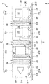
FIGS. 1 ,3 , and4 . The powerless carrier 5 (hereinafter, simply referred to as a carrier 5) includes achassis section 21 and abody section 25, which are provided as base members thereof. Thecarrier 5 does not carry any power source for running. As described later, kinetic energy converted from potential energy serves as energy at the time of power generation. Thechassis member 21 is basically constructed of ahead chassis section 21a and asuccessive chassis section 21b that follows thehead chassis section 21 a. Two or moresuccessive chassis sections 21b may be provided even though only necessary is at least one. In this embodiment, the number of the successive chassis sections is three, including asuccessive chassis 21 b on which a wind power generating mechanism is mounted andsuccessive chassis sections 21c to 21 d on which a wheel power generating mechanism is mounted. As another embodiment, the wind power generating mechanism is only connected or the wheel power generating mechanism is only connected. When connecting the wheel power generating mechanism, the head section is formed in a streamline shape with a small air resistance. The back end of thehead chassis section 21a in the travelling direction is connected to the front end of thesuccessive chassis section 21b in the same direction via a joint 22. The joint 22 has a joint structure that allows, when thecarrier 5 vertically or horizontally changes its travelling direction, thesuccessive chassis section 21b to follow a change in travelling direction of thecarrier 5 with respect to thehead chassis section 21a. The above joints 22 are also used in connection between thesuccessive chassis 21b and thesuccessive chassis 21c and connection between thesuccessive chassis 21c and thesuccessive chassis 21d. A plurality ofwheels 23 is attached to the both sides of each of thehead chassis section 21a and thesuccessive chassis sections 21b to 21 d so that these wheels can rotate on therail 3. Thebody section 25 includes ahead body part 25a andsuccessive body parts 25b to 25d. Thehead body part 25a corresponds to thehead chassis section 21a, and thesuccessive body parts 25b to 25d correspond to thesuccessive chassis sections 21b to 21d, respectively. The body parts are connected to each other via anaccordion structure 26. The connection with theaccordion structure 26 is provided so as to be allowed to follow a vertical or horizontal change in travelling direction by flexible elasticity in a manner similar to the joint 22, and so as to block a leakage of air incorporated into the body to the outside as far as possible by its airtightness. Furthermore, a wing or weight, yaw control rotary impeller, or the like for obtaining down force may be provided on the inside or outside of the body if required. InFIGS. 3 and4 , each vehicle has four wheels. However, the number of wheels per vehicle is not limited to four. - A wind power generating mechanism (hereinafter, referred to as a power generating mechanism 11) is illustrated in
FIGS. 3 and4 . Thepower generating mechanism 11 is mounted on each of thehead chassis section 21a and thesuccessive chassis section 21b and is configured to be able to generate electric power by running wind w (seeFIG. 4 ) caused by running of thecarrier 5. In other words, thepower generating mechanism 11 mainly includes: a cannonball-shapedhead section 27 mounted on thehead chassis 21 a, animpeller 9 and apower generator 12 mounted on thesuccessive chassis section 21 b, and a power-generation air passage 29 surrounded by thechassis section 21 and thebody section 25. First, the power-generation air passage 29 will be illustrated. In the power-generation air passage 29, a runningair intake port 31 is formed as a starting point and opened at the tip of ahead body part 25a in a travelling direction and the back end of thesuccessive body part 25d is formed as an end point communicated with the starting point via thesuccessive body parts air intake port 31 passes through the power-generation air passage 29 and is then discharged from aroute outlet port 33. - In the power-
generation air passage 29, animpeller 9 is arranged so that it can be rotated by efficiently receiving the running wind w. An output axis of theimpeller 9 is attached to the rotor of thepower generator 12 to rotate integrally with the rotor. The combination of these structural components allow the rotor of the power generator 12 (the rotor is located in the inside of the power generator 12) to rotate by rotation of theimpeller 9 so that generated electric power can be taken out from thepower output terminal 13 of thepower generator 12. The installation direction, angle, and the like of the impeller can be flexibly defined. - On the other hand, instead of the wind
power generating mechanism 11, a wheel power generating mechanism 11a is mounted on each of thesuccessive chassis sections power generator 12a, awheel 23, and agearbox 24 disposed between thepower generating mechanism 12a and thewheel 23. That is, thewheel 23 is rotationally connected to the rotor of thepower generator 12a (the rotor is not shown because of being inside thepower generator 12a). The rotation of thewheel 23 running on therail 3 causes thepower generator 12a to generate electric power. The electric power generated by thepower generator 12a can be taken out from thepower output terminal 13a. - If required, the
battery charger 15 can be removably mounted on each of thesuccessive chassis sections
The electric power generated from thepower generator 12 and the electric power generated from thepower generator 12a can be respectively charged into thebattery charger 15. - Referring now to
FIGS. 1 and2 , the operation and effects of the present embodiment are described. When thecarrier 5 located at thehighest place 3a illustrated inFIG. 1 is released from restriction with the transporter A51, thecarrier 5 runs on therail 3 toward thelowest place 3f via theintermediate points 3b to 3d while converting its potential energy into kinetic energy. When passing through thelowest place 3f, due to inertia, thecarrier 5 runs upward and reaches to thetransportation starting point 3g while newly obtaining potential energy. Subsequently, after passing through thetransportation starting point 3g, thecarrier 5 is transported by the transporter B7 to thehighest place 3e. Consequently, the run of thecarrier 5 is looped back to the start. If required, the same run is repeated. In this embodiment, descent and ascent are respectively repeated four times, but may be performed in other cycles. - During the run, the running wind w is incorporated into the power-
generation air passage 29 of thecarrier 5. The incorporated running wind w rotates theimpeller 9. The rotation of theimpeller 9 causes thepower generator 12 to generate electric power. Then, the generated electric power is charged into thebattery charger 15 via thepower output terminal 13 or supplied to the outside via the power-feedingrail 4 or the like. On the other hand, the rotation of thewheel 23 accompanying the run of thecarrier 5 causes thepower generator 12a to generate electric power. Likewise, the generated electric power is charged or supplied to the outside via thepower output terminal 13. - Thus, according to the power supply system 1, electric power can be generated using potential energy obtained by the
carrier 5. - Referring now to
FIG. 5 , a modified example of the transporter A51 is described. The transporter A51 generally includes alarge diameter tank 53, asmall diameter tank 55, an up/downarm 59, aconnection tank 57 connecting between thelarge diameter tank 53 and thesmall diameter tank 55, and is filled with oil or the like. The up/downarm 59 is able to expand and contract (up and down) with respect to thesmall diameter tank 55 by means of oil pressure or the like. Alarge diameter plate 53a floats on the liquid surface of thelarge diameter tank 53. A part ofsmall diameter plate 55a and running rail 3 (orbit) (this is called 3h) are attached to the upper bed of up/downarm 59. Thesmall diameter plate 55a is made larger than the bases area of the small diameter tank so that it may not go into the ground more than needed. Thelarge diameter plate 53a is configured to allow several vehicles to be parked thereon and the weight thereof can be adjusted by parking and retrieving the vehicles. - The operation of the transporter A51 is described. The steady state of the transporter A51 is a state where the
carrier 5 is at the same level as the ground as illustrated inFIG. 5 . The runningrail 3 is configured such that part thereof located on thehighest place 3a can be removable. When the up/downarm 59 of a hydraulic type or the like, which is closely attached to the lower portion of the removable part (hereinafter, referred to as aremoval part 3h), satisfies the following inequality 1, the up/downarm 59 moves upward to bring thecarrier 5 thereon up to thehighest place 3a.
carrier 5 is requested to be pulled down, or to be returned to the steady state, the followinginequality 2 should be satisfied.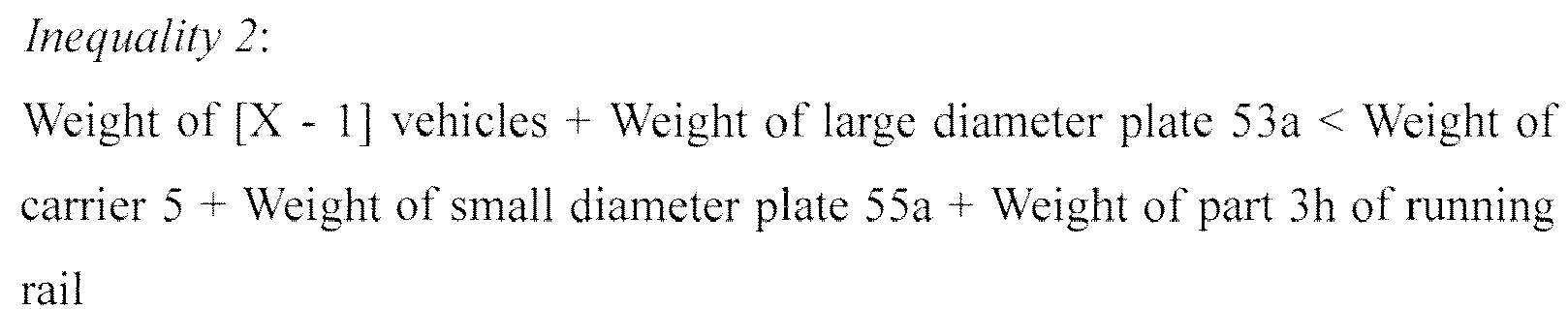
arm 59 is pulled down after releasing the carrier, the followinginequality 3 should be satisfied.
large diameter tank 53 is several times larger than the base area of thesmall diameter tank 55. Thus, an increasing distance of thesmall diameter plate 55a can be several times larger than the decreasing distance of thelarge diameter plate 53a. - The power supply system mentioned above can also be realized by flexible use of the existing equipment. In other words, a so-called roller coaster is provided with the impeller or the like which are installed in the carrier, and allowed to run on the rail to make power generation possible using potential energy. Furthermore, for example, when playground equipment such as a roller coaster is suspended, an amusement park is closed, or operation thereof is stopped, the flexible use or diversion of part or whole of the roller coaster in the power supply system of the present invention is also included.
- 1...Power supply system, 2...Orbit, 3...Running rail (figure-of-eight rail), 4...Power-feeding rail, 5...Powerless carrier (carrier), 7...Transporter B, 9...Impeller, 11...Wind power generating mechanism (power generating mechanism), 11 a... Wheel power generating mechanism (power generating mechanism), 12...Power generator, 12a... Power generator, 13...Power output terminal, 13a...Power output terminal, 15...Battery charger, 21...Chassis section, 21a...Head chassis, 21b...Successive chassis, 53a...Large diameter plate, 55a...Small diameter plate, 55...Small diameter tank, 57...Connection layer, 59...Up/down arm, W...running wind, 3h...Rail-removing portion, 21c...Successive chassis, 21d...Successive chassis, 22...Joint, 23...Wheel, 24...Gearbox, 25...Body section, 25a...Head body part, 25b to d...successive body part, 26...Accordion structure, 27...Head section, 29...power-generation air passage having, 31...Running air intake port, 33...Route outlet port, 51...Transporter A, 53...Large diameter tank, 6...Thread type rail, 8...Switching point
Claims (4)
- A power supply system comprising:a running rail having at least one low place and at least one high place located at a level higher than the low place in a gravity direction;a powerless carrier placed on the running rail so as to be run on the running rail;a powerless transporter, and if required a powered transporter, for transporting the powerless carrier to the high place;a wind power generating mechanism with an impeller, the mechanism being provided on the powerless carrier; anda power output terminal provided on the wind power generating mechanism,wherein electric power generated by rotation of the impeller directly or indirectly caused by running wind generated by running of the powerless carrier can be taken out from the running rail electrically connected to the power output terminal or taken out from a power-feeding rail or an overhead power line arranged in parallel to the running rail.
- The power supply system according to claim 1, wherein the wind power generating mechanism includes a power-generation air passage having a running air intake port for allowing running wind to be incorporated into the wind power generating mechanism and a route outlet port for allowing the running wind incorporated from the running air intake port to be discharged to an outside of a vehicle, and
wherein the impeller is arranged in the power-generation air passage and is configured to be rotated by receiving running wind incorporated from the running air intake port. - The power supply system according to claim 1 or 2, wherein the powerless carrier is placed on the running rail via a plurality of wheels, at least one wheel among the wheels being connected to a wheel power generating mechanism to allow the wheel power generating mechanism to generate electric power, and
wherein the wheel power generating mechanism is configured to take the generated electric power from a power output terminal thereof. - The power supply system according to any one of claims 1 to 3, wherein the powerless carrier is a roller coaster.
Applications Claiming Priority (2)
| Application Number | Priority Date | Filing Date | Title |
|---|---|---|---|
| JP2012085876A JP5051676B1 (en) | 2012-03-19 | 2012-03-19 | Power supply system |
| PCT/JP2012/081162 WO2013140672A1 (en) | 2012-03-19 | 2012-11-30 | Power supply system |
Publications (3)
| Publication Number | Publication Date |
|---|---|
| EP2829725A1 EP2829725A1 (en) | 2015-01-28 |
| EP2829725A4 EP2829725A4 (en) | 2015-10-28 |
| EP2829725B1 true EP2829725B1 (en) | 2017-02-01 |
Family
ID=47189490
Family Applications (1)
| Application Number | Title | Priority Date | Filing Date |
|---|---|---|---|
| EP12872239.4A Not-in-force EP2829725B1 (en) | 2012-03-19 | 2012-11-30 | Power supply system |
Country Status (8)
| Country | Link |
|---|---|
| US (1) | US20140145438A1 (en) |
| EP (1) | EP2829725B1 (en) |
| JP (1) | JP5051676B1 (en) |
| KR (1) | KR20140142713A (en) |
| CN (1) | CN103429890B (en) |
| DE (1) | DE112012006053T5 (en) |
| TW (1) | TW201339419A (en) |
| WO (1) | WO2013140672A1 (en) |
Families Citing this family (5)
| Publication number | Priority date | Publication date | Assignee | Title |
|---|---|---|---|---|
| US20120119508A1 (en) * | 2010-11-12 | 2012-05-17 | Ushijima Shiro Cresto Sparks | Gravity and Buoyancy Electricity Generation System |
| TW201525283A (en) * | 2013-12-30 | 2015-07-01 | Jun Fu Clean Energy Co Ltd | Circulating power plant |
| KR102833968B1 (en) * | 2020-08-10 | 2025-07-14 | 한국전력공사 | Energy storage apparatus, power generation system having the same and method |
| JP7377584B1 (en) * | 2023-08-14 | 2023-11-10 | 株式会社フォトラダ | Power generation equipment |
| CN117302884B (en) * | 2023-10-26 | 2025-09-09 | 湖南中矿金禾机器人研究院有限公司 | Mine solid waste gravity energy storage and bulk material rail transportation control system |
Family Cites Families (25)
| Publication number | Priority date | Publication date | Assignee | Title |
|---|---|---|---|---|
| US1670007A (en) * | 1926-01-23 | 1928-05-15 | Christian H Rasmussen | Power car |
| US4326154A (en) * | 1978-12-08 | 1982-04-20 | Westinghouse Electric Corp. | Regenerative braking control for a transit vehicle |
| JPH076944Y2 (en) * | 1988-09-12 | 1995-02-22 | 株式会社石井鐵工所 | Leisure downhill equipment |
| JPH0754762A (en) * | 1993-08-11 | 1995-02-28 | Railway Technical Res Inst | Wind turbine generator for magnetic levitation vehicle |
| US6107691A (en) * | 1995-11-14 | 2000-08-22 | Grow International Corp. | Methods for utilizing the electrical and non electrical outputs of fuel cell powered vehicles |
| DE20003950U1 (en) * | 2000-03-08 | 2001-07-19 | Spieldiener, Patrick, Schaan | Towing device for vehicles on amusement devices |
| JP2001286683A (en) * | 2000-04-05 | 2001-10-16 | Joji Taira | Vehicle for play |
| CA2357580A1 (en) * | 2001-09-21 | 2003-03-21 | Shiang-Huei Wu | Multiple installation variegated generators for fossil fuel- and electric-powered vehicles |
| US6837166B1 (en) * | 2002-07-15 | 2005-01-04 | Joop Roodenburg | Rollercoaster launch system |
| US6956300B2 (en) * | 2003-08-04 | 2005-10-18 | Andrew Roman Gizara | Gimbal-mounted hydroelectric turbine |
| US7453166B2 (en) * | 2006-06-06 | 2008-11-18 | Oceana Energy Company | System for generating electricity from fluid currents |
| US8528487B2 (en) * | 2007-08-01 | 2013-09-10 | Sandor Wayne Shapery Wayne Shapery | System and method for operating a vehicle in multiple transportation networks |
| EP2036599A1 (en) * | 2007-09-11 | 2009-03-18 | Maurer Söhne GmbH & Co. KG | Ride, safety system, method for operating a ride and method for inserting a vehicle in a ride |
| US8117968B2 (en) * | 2007-11-05 | 2012-02-21 | Disney Enterprises, Inc. | Magnetic pacer for controlling speeds in amusement park rides |
| US20110080004A1 (en) * | 2008-05-06 | 2011-04-07 | Altaf Hadi | Renewable energy generation eco system |
| KR101011756B1 (en) * | 2008-10-15 | 2011-02-07 | 정학규 | Transport device using sliding movement of heavy material by gravity action |
| JP5207957B2 (en) | 2008-12-24 | 2013-06-12 | シャープ株式会社 | Vehicle with wind power generation mechanism |
| US8640629B2 (en) * | 2009-05-01 | 2014-02-04 | Norfolk Southern Corporation | Battery-powered all-electric and/or hybrid locomotive and related locomotive and train configurations |
| RU2492072C1 (en) * | 2009-08-17 | 2013-09-10 | Мицубиси Электрик Корпорейшн | Electric rolling stock electric power converter |
| CN201526422U (en) * | 2009-11-13 | 2010-07-14 | 刘新广 | Rail wind power generator |
| JP5176244B2 (en) * | 2010-01-09 | 2013-04-03 | 正治 加藤 | On-board wind turbine generator |
| JP2011144794A (en) * | 2010-01-18 | 2011-07-28 | Haruo Shigei | Wind turbine generator using head wind to be generated in response to speed in travelling of vehicle and sailing of ship |
| JP2011157865A (en) | 2010-01-31 | 2011-08-18 | Satoshi Sasaki | Mobile wind turbine generator |
| JP2012044852A (en) * | 2010-08-23 | 2012-03-01 | Tadanori Tanaka | Method of generating electric power needed for ev vehicle and hybrid vehicle continuously by rotating motor of generator owing to energy generated naturally during traveling |
| US8505464B2 (en) * | 2011-12-01 | 2013-08-13 | Caterpillar Inc. | Control strategy for providing regenerative electrical power to trolley line in trolley capable mining truck |
-
2012
- 2012-03-19 JP JP2012085876A patent/JP5051676B1/en not_active Expired - Fee Related
- 2012-11-30 KR KR1020147027547A patent/KR20140142713A/en not_active Ceased
- 2012-11-30 EP EP12872239.4A patent/EP2829725B1/en not_active Not-in-force
- 2012-11-30 DE DE112012006053.9T patent/DE112012006053T5/en not_active Withdrawn
- 2012-11-30 WO PCT/JP2012/081162 patent/WO2013140672A1/en not_active Ceased
- 2012-11-30 CN CN201280010907.5A patent/CN103429890B/en not_active Expired - Fee Related
- 2012-11-30 US US14/234,922 patent/US20140145438A1/en not_active Abandoned
- 2012-12-25 TW TW101149911A patent/TW201339419A/en unknown
Non-Patent Citations (1)
| Title |
|---|
| None * |
Also Published As
| Publication number | Publication date |
|---|---|
| CN103429890B (en) | 2016-01-20 |
| KR20140142713A (en) | 2014-12-12 |
| JP2013194728A (en) | 2013-09-30 |
| JP5051676B1 (en) | 2012-10-17 |
| DE112012006053T5 (en) | 2015-01-15 |
| US20140145438A1 (en) | 2014-05-29 |
| WO2013140672A1 (en) | 2013-09-26 |
| EP2829725A1 (en) | 2015-01-28 |
| EP2829725A4 (en) | 2015-10-28 |
| CN103429890A (en) | 2013-12-04 |
| TW201339419A (en) | 2013-10-01 |
Similar Documents
| Publication | Publication Date | Title |
|---|---|---|
| EP2829725B1 (en) | Power supply system | |
| CN107839696B (en) | Permanent magnet shaft type direct-drive air-ground sharing three-dimensional rapid rail transit system | |
| US20100025160A1 (en) | Gravity Powered Rail, Road and Runway transportation systems | |
| CN102359044B (en) | A kind of public transportation system and its method of construction | |
| CN107554534A (en) | A kind of dual-purpose shared traffic system for overhead track in new energy vacant lot and operation method | |
| CN101200188A (en) | Bulk transport system | |
| CA2739534A1 (en) | Smart mass transit rail system | |
| US20190232796A1 (en) | Autonomous networked transportation system and method | |
| CN102224051A (en) | Vehicle, system and method for mass transit transportation | |
| CN202098411U (en) | Public traffic system for trolley hoist | |
| KR20130081565A (en) | Subway Wind Power Generator | |
| CN202577079U (en) | Public traffic system | |
| CN103129562A (en) | Monorail magnetic suspension electric car | |
| CN101992784A (en) | Novel rail transit method and system thereof | |
| CN201520295U (en) | Rail transit system | |
| CN103738342B (en) | Independent-drive cableway transport system | |
| WO2010023500A1 (en) | Gravity powered rail, road and runway transportation system | |
| CN208789668U (en) | Urban cable car transport system powered by solar, wind and gravitational potential energy | |
| CN203996235U (en) | A kind of double dynamical mass transit system | |
| US10903722B2 (en) | Gravity line power generation system including a sled mechanism to harvest kinetic energy from a wheeled vehicle moving down a slope | |
| CN102039899A (en) | Continuous conveying type urban track traffic system | |
| CN204701609U (en) | A kind of Air Traffic System | |
| RU2332311C1 (en) | Vehicle | |
| KR20130072381A (en) | Wind power generation system using wind occurred by moving body's running and methods for controlling the same | |
| CN105539459B (en) | The planer-type solid vehicles |
Legal Events
| Date | Code | Title | Description |
|---|---|---|---|
| PUAI | Public reference made under article 153(3) epc to a published international application that has entered the european phase |
Free format text: ORIGINAL CODE: 0009012 |
|
| 17P | Request for examination filed |
Effective date: 20140910 |
|
| AK | Designated contracting states |
Kind code of ref document: A1 Designated state(s): AL AT BE BG CH CY CZ DE DK EE ES FI FR GB GR HR HU IE IS IT LI LT LU LV MC MK MT NL NO PL PT RO RS SE SI SK SM TR |
|
| AX | Request for extension of the european patent |
Extension state: BA ME |
|
| DAX | Request for extension of the european patent (deleted) | ||
| RA4 | Supplementary search report drawn up and despatched (corrected) |
Effective date: 20150928 |
|
| RIC1 | Information provided on ipc code assigned before grant |
Ipc: F03D 5/04 20060101ALI20150922BHEP Ipc: F03G 3/00 20060101ALI20150922BHEP Ipc: A63G 21/00 20060101ALI20150922BHEP Ipc: H02K 53/00 20060101ALI20150922BHEP Ipc: F03D 9/00 20060101AFI20150922BHEP |
|
| GRAP | Despatch of communication of intention to grant a patent |
Free format text: ORIGINAL CODE: EPIDOSNIGR1 |
|
| INTG | Intention to grant announced |
Effective date: 20160901 |
|
| GRAS | Grant fee paid |
Free format text: ORIGINAL CODE: EPIDOSNIGR3 |
|
| STAA | Information on the status of an ep patent application or granted ep patent |
Free format text: STATUS: GRANT OF PATENT IS INTENDED |
|
| GRAA | (expected) grant |
Free format text: ORIGINAL CODE: 0009210 |
|
| STAA | Information on the status of an ep patent application or granted ep patent |
Free format text: STATUS: THE PATENT HAS BEEN GRANTED |
|
| AK | Designated contracting states |
Kind code of ref document: B1 Designated state(s): AL AT BE BG CH CY CZ DE DK EE ES FI FR GB GR HR HU IE IS IT LI LT LU LV MC MK MT NL NO PL PT RO RS SE SI SK SM TR |
|
| REG | Reference to a national code |
Ref country code: GB Ref legal event code: FG4D |
|
| REG | Reference to a national code |
Ref country code: CH Ref legal event code: EP Ref country code: AT Ref legal event code: REF Ref document number: 865827 Country of ref document: AT Kind code of ref document: T Effective date: 20170215 |
|
| REG | Reference to a national code |
Ref country code: IE Ref legal event code: FG4D |
|
| REG | Reference to a national code |
Ref country code: DE Ref legal event code: R096 Ref document number: 602012028481 Country of ref document: DE |
|
| REG | Reference to a national code |
Ref country code: NL Ref legal event code: MP Effective date: 20170201 |
|
| REG | Reference to a national code |
Ref country code: LT Ref legal event code: MG4D |
|
| REG | Reference to a national code |
Ref country code: AT Ref legal event code: MK05 Ref document number: 865827 Country of ref document: AT Kind code of ref document: T Effective date: 20170201 |
|
| PG25 | Lapsed in a contracting state [announced via postgrant information from national office to epo] |
Ref country code: HR Free format text: LAPSE BECAUSE OF FAILURE TO SUBMIT A TRANSLATION OF THE DESCRIPTION OR TO PAY THE FEE WITHIN THE PRESCRIBED TIME-LIMIT Effective date: 20170201 Ref country code: FI Free format text: LAPSE BECAUSE OF FAILURE TO SUBMIT A TRANSLATION OF THE DESCRIPTION OR TO PAY THE FEE WITHIN THE PRESCRIBED TIME-LIMIT Effective date: 20170201 Ref country code: NO Free format text: LAPSE BECAUSE OF FAILURE TO SUBMIT A TRANSLATION OF THE DESCRIPTION OR TO PAY THE FEE WITHIN THE PRESCRIBED TIME-LIMIT Effective date: 20170501 Ref country code: IS Free format text: LAPSE BECAUSE OF FAILURE TO SUBMIT A TRANSLATION OF THE DESCRIPTION OR TO PAY THE FEE WITHIN THE PRESCRIBED TIME-LIMIT Effective date: 20170601 Ref country code: GR Free format text: LAPSE BECAUSE OF FAILURE TO SUBMIT A TRANSLATION OF THE DESCRIPTION OR TO PAY THE FEE WITHIN THE PRESCRIBED TIME-LIMIT Effective date: 20170502 Ref country code: LT Free format text: LAPSE BECAUSE OF FAILURE TO SUBMIT A TRANSLATION OF THE DESCRIPTION OR TO PAY THE FEE WITHIN THE PRESCRIBED TIME-LIMIT Effective date: 20170201 |
|
| PG25 | Lapsed in a contracting state [announced via postgrant information from national office to epo] |
Ref country code: RS Free format text: LAPSE BECAUSE OF FAILURE TO SUBMIT A TRANSLATION OF THE DESCRIPTION OR TO PAY THE FEE WITHIN THE PRESCRIBED TIME-LIMIT Effective date: 20170201 Ref country code: LV Free format text: LAPSE BECAUSE OF FAILURE TO SUBMIT A TRANSLATION OF THE DESCRIPTION OR TO PAY THE FEE WITHIN THE PRESCRIBED TIME-LIMIT Effective date: 20170201 Ref country code: ES Free format text: LAPSE BECAUSE OF FAILURE TO SUBMIT A TRANSLATION OF THE DESCRIPTION OR TO PAY THE FEE WITHIN THE PRESCRIBED TIME-LIMIT Effective date: 20170201 Ref country code: NL Free format text: LAPSE BECAUSE OF FAILURE TO SUBMIT A TRANSLATION OF THE DESCRIPTION OR TO PAY THE FEE WITHIN THE PRESCRIBED TIME-LIMIT Effective date: 20170201 Ref country code: SE Free format text: LAPSE BECAUSE OF FAILURE TO SUBMIT A TRANSLATION OF THE DESCRIPTION OR TO PAY THE FEE WITHIN THE PRESCRIBED TIME-LIMIT Effective date: 20170201 Ref country code: AT Free format text: LAPSE BECAUSE OF FAILURE TO SUBMIT A TRANSLATION OF THE DESCRIPTION OR TO PAY THE FEE WITHIN THE PRESCRIBED TIME-LIMIT Effective date: 20170201 Ref country code: BG Free format text: LAPSE BECAUSE OF FAILURE TO SUBMIT A TRANSLATION OF THE DESCRIPTION OR TO PAY THE FEE WITHIN THE PRESCRIBED TIME-LIMIT Effective date: 20170501 Ref country code: PT Free format text: LAPSE BECAUSE OF FAILURE TO SUBMIT A TRANSLATION OF THE DESCRIPTION OR TO PAY THE FEE WITHIN THE PRESCRIBED TIME-LIMIT Effective date: 20170601 Ref country code: PL Free format text: LAPSE BECAUSE OF FAILURE TO SUBMIT A TRANSLATION OF THE DESCRIPTION OR TO PAY THE FEE WITHIN THE PRESCRIBED TIME-LIMIT Effective date: 20170201 |
|
| PG25 | Lapsed in a contracting state [announced via postgrant information from national office to epo] |
Ref country code: EE Free format text: LAPSE BECAUSE OF FAILURE TO SUBMIT A TRANSLATION OF THE DESCRIPTION OR TO PAY THE FEE WITHIN THE PRESCRIBED TIME-LIMIT Effective date: 20170201 Ref country code: IT Free format text: LAPSE BECAUSE OF FAILURE TO SUBMIT A TRANSLATION OF THE DESCRIPTION OR TO PAY THE FEE WITHIN THE PRESCRIBED TIME-LIMIT Effective date: 20170201 Ref country code: CZ Free format text: LAPSE BECAUSE OF FAILURE TO SUBMIT A TRANSLATION OF THE DESCRIPTION OR TO PAY THE FEE WITHIN THE PRESCRIBED TIME-LIMIT Effective date: 20170201 Ref country code: SK Free format text: LAPSE BECAUSE OF FAILURE TO SUBMIT A TRANSLATION OF THE DESCRIPTION OR TO PAY THE FEE WITHIN THE PRESCRIBED TIME-LIMIT Effective date: 20170201 Ref country code: RO Free format text: LAPSE BECAUSE OF FAILURE TO SUBMIT A TRANSLATION OF THE DESCRIPTION OR TO PAY THE FEE WITHIN THE PRESCRIBED TIME-LIMIT Effective date: 20170201 |
|
| REG | Reference to a national code |
Ref country code: DE Ref legal event code: R097 Ref document number: 602012028481 Country of ref document: DE |
|
| PG25 | Lapsed in a contracting state [announced via postgrant information from national office to epo] |
Ref country code: DK Free format text: LAPSE BECAUSE OF FAILURE TO SUBMIT A TRANSLATION OF THE DESCRIPTION OR TO PAY THE FEE WITHIN THE PRESCRIBED TIME-LIMIT Effective date: 20170201 Ref country code: SM Free format text: LAPSE BECAUSE OF FAILURE TO SUBMIT A TRANSLATION OF THE DESCRIPTION OR TO PAY THE FEE WITHIN THE PRESCRIBED TIME-LIMIT Effective date: 20170201 |
|
| PLBE | No opposition filed within time limit |
Free format text: ORIGINAL CODE: 0009261 |
|
| STAA | Information on the status of an ep patent application or granted ep patent |
Free format text: STATUS: NO OPPOSITION FILED WITHIN TIME LIMIT |
|
| 26N | No opposition filed |
Effective date: 20171103 |
|
| PG25 | Lapsed in a contracting state [announced via postgrant information from national office to epo] |
Ref country code: SI Free format text: LAPSE BECAUSE OF FAILURE TO SUBMIT A TRANSLATION OF THE DESCRIPTION OR TO PAY THE FEE WITHIN THE PRESCRIBED TIME-LIMIT Effective date: 20170201 |
|
| REG | Reference to a national code |
Ref country code: DE Ref legal event code: R119 Ref document number: 602012028481 Country of ref document: DE |
|
| PG25 | Lapsed in a contracting state [announced via postgrant information from national office to epo] |
Ref country code: MC Free format text: LAPSE BECAUSE OF FAILURE TO SUBMIT A TRANSLATION OF THE DESCRIPTION OR TO PAY THE FEE WITHIN THE PRESCRIBED TIME-LIMIT Effective date: 20170201 |
|
| GBPC | Gb: european patent ceased through non-payment of renewal fee |
Effective date: 20171130 |
|
| PG25 | Lapsed in a contracting state [announced via postgrant information from national office to epo] |
Ref country code: CH Free format text: LAPSE BECAUSE OF NON-PAYMENT OF DUE FEES Effective date: 20171130 Ref country code: LI Free format text: LAPSE BECAUSE OF NON-PAYMENT OF DUE FEES Effective date: 20171130 |
|
| PG25 | Lapsed in a contracting state [announced via postgrant information from national office to epo] |
Ref country code: LU Free format text: LAPSE BECAUSE OF NON-PAYMENT OF DUE FEES Effective date: 20171130 |
|
| REG | Reference to a national code |
Ref country code: FR Ref legal event code: ST Effective date: 20180731 Ref country code: BE Ref legal event code: MM Effective date: 20171130 |
|
| REG | Reference to a national code |
Ref country code: IE Ref legal event code: MM4A |
|
| PG25 | Lapsed in a contracting state [announced via postgrant information from national office to epo] |
Ref country code: MT Free format text: LAPSE BECAUSE OF NON-PAYMENT OF DUE FEES Effective date: 20171130 |
|
| PG25 | Lapsed in a contracting state [announced via postgrant information from national office to epo] |
Ref country code: DE Free format text: LAPSE BECAUSE OF NON-PAYMENT OF DUE FEES Effective date: 20180602 Ref country code: IE Free format text: LAPSE BECAUSE OF NON-PAYMENT OF DUE FEES Effective date: 20171130 Ref country code: FR Free format text: LAPSE BECAUSE OF NON-PAYMENT OF DUE FEES Effective date: 20171130 |
|
| PG25 | Lapsed in a contracting state [announced via postgrant information from national office to epo] |
Ref country code: GB Free format text: LAPSE BECAUSE OF NON-PAYMENT OF DUE FEES Effective date: 20171130 Ref country code: BE Free format text: LAPSE BECAUSE OF NON-PAYMENT OF DUE FEES Effective date: 20171130 |
|
| PG25 | Lapsed in a contracting state [announced via postgrant information from national office to epo] |
Ref country code: HU Free format text: LAPSE BECAUSE OF FAILURE TO SUBMIT A TRANSLATION OF THE DESCRIPTION OR TO PAY THE FEE WITHIN THE PRESCRIBED TIME-LIMIT; INVALID AB INITIO Effective date: 20121130 |
|
| PG25 | Lapsed in a contracting state [announced via postgrant information from national office to epo] |
Ref country code: CY Free format text: LAPSE BECAUSE OF FAILURE TO SUBMIT A TRANSLATION OF THE DESCRIPTION OR TO PAY THE FEE WITHIN THE PRESCRIBED TIME-LIMIT Effective date: 20170201 |
|
| PG25 | Lapsed in a contracting state [announced via postgrant information from national office to epo] |
Ref country code: MK Free format text: LAPSE BECAUSE OF FAILURE TO SUBMIT A TRANSLATION OF THE DESCRIPTION OR TO PAY THE FEE WITHIN THE PRESCRIBED TIME-LIMIT Effective date: 20170201 |
|
| PG25 | Lapsed in a contracting state [announced via postgrant information from national office to epo] |
Ref country code: TR Free format text: LAPSE BECAUSE OF FAILURE TO SUBMIT A TRANSLATION OF THE DESCRIPTION OR TO PAY THE FEE WITHIN THE PRESCRIBED TIME-LIMIT Effective date: 20170201 |
|
| PG25 | Lapsed in a contracting state [announced via postgrant information from national office to epo] |
Ref country code: AL Free format text: LAPSE BECAUSE OF FAILURE TO SUBMIT A TRANSLATION OF THE DESCRIPTION OR TO PAY THE FEE WITHIN THE PRESCRIBED TIME-LIMIT Effective date: 20170201 |