EP2829250B1 - Implant dentaire, butée, système d'implant et jeu d'implantation - Google Patents
Implant dentaire, butée, système d'implant et jeu d'implantation Download PDFInfo
- Publication number
- EP2829250B1 EP2829250B1 EP13178279.9A EP13178279A EP2829250B1 EP 2829250 B1 EP2829250 B1 EP 2829250B1 EP 13178279 A EP13178279 A EP 13178279A EP 2829250 B1 EP2829250 B1 EP 2829250B1
- Authority
- EP
- European Patent Office
- Prior art keywords
- abutment
- section
- implant
- dental implant
- cone
- Prior art date
- Legal status (The legal status is an assumption and is not a legal conclusion. Google has not performed a legal analysis and makes no representation as to the accuracy of the status listed.)
- Active
Links
- 239000007943 implant Substances 0.000 title claims description 98
- 239000004053 dental implant Substances 0.000 title claims description 64
- 238000002513 implantation Methods 0.000 title claims description 14
- -1 abutment Substances 0.000 title 1
- 238000013461 design Methods 0.000 claims description 7
- 210000002050 maxilla Anatomy 0.000 claims 1
- 238000003466 welding Methods 0.000 description 17
- 238000003780 insertion Methods 0.000 description 13
- 230000037431 insertion Effects 0.000 description 13
- 210000000988 bone and bone Anatomy 0.000 description 8
- 210000004195 gingiva Anatomy 0.000 description 8
- 238000004519 manufacturing process Methods 0.000 description 7
- 230000007704 transition Effects 0.000 description 7
- 230000001055 chewing effect Effects 0.000 description 5
- 238000005516 engineering process Methods 0.000 description 5
- 241000894006 Bacteria Species 0.000 description 4
- 238000012546 transfer Methods 0.000 description 4
- 238000011109 contamination Methods 0.000 description 3
- 239000007788 liquid Substances 0.000 description 3
- 206010065687 Bone loss Diseases 0.000 description 2
- RTAQQCXQSZGOHL-UHFFFAOYSA-N Titanium Chemical compound [Ti] RTAQQCXQSZGOHL-UHFFFAOYSA-N 0.000 description 2
- 238000005452 bending Methods 0.000 description 2
- 230000005540 biological transmission Effects 0.000 description 2
- 238000010276 construction Methods 0.000 description 2
- 230000005489 elastic deformation Effects 0.000 description 2
- 230000002349 favourable effect Effects 0.000 description 2
- 238000000227 grinding Methods 0.000 description 2
- 230000014759 maintenance of location Effects 0.000 description 2
- 239000000463 material Substances 0.000 description 2
- 238000000034 method Methods 0.000 description 2
- 229910052719 titanium Inorganic materials 0.000 description 2
- 239000010936 titanium Substances 0.000 description 2
- 229910001069 Ti alloy Inorganic materials 0.000 description 1
- 230000015572 biosynthetic process Effects 0.000 description 1
- 230000000903 blocking effect Effects 0.000 description 1
- 230000037176 bone building Effects 0.000 description 1
- 230000007423 decrease Effects 0.000 description 1
- 210000004513 dentition Anatomy 0.000 description 1
- 230000001419 dependent effect Effects 0.000 description 1
- 238000006073 displacement reaction Methods 0.000 description 1
- 238000001125 extrusion Methods 0.000 description 1
- 238000000465 moulding Methods 0.000 description 1
- 230000035515 penetration Effects 0.000 description 1
- 238000007789 sealing Methods 0.000 description 1
- 238000007493 shaping process Methods 0.000 description 1
- 238000012360 testing method Methods 0.000 description 1
- 230000036346 tooth eruption Effects 0.000 description 1
Images


Classifications
-
- A—HUMAN NECESSITIES
- A61—MEDICAL OR VETERINARY SCIENCE; HYGIENE
- A61C—DENTISTRY; APPARATUS OR METHODS FOR ORAL OR DENTAL HYGIENE
- A61C8/00—Means to be fixed to the jaw-bone for consolidating natural teeth or for fixing dental prostheses thereon; Dental implants; Implanting tools
- A61C8/0048—Connecting the upper structure to the implant, e.g. bridging bars
- A61C8/005—Connecting devices for joining an upper structure with an implant member, e.g. spacers
- A61C8/0066—Connecting devices for joining an upper structure with an implant member, e.g. spacers with positioning means
-
- A—HUMAN NECESSITIES
- A61—MEDICAL OR VETERINARY SCIENCE; HYGIENE
- A61C—DENTISTRY; APPARATUS OR METHODS FOR ORAL OR DENTAL HYGIENE
- A61C8/00—Means to be fixed to the jaw-bone for consolidating natural teeth or for fixing dental prostheses thereon; Dental implants; Implanting tools
- A61C8/0001—Impression means for implants, e.g. impression coping
-
- A—HUMAN NECESSITIES
- A61—MEDICAL OR VETERINARY SCIENCE; HYGIENE
- A61C—DENTISTRY; APPARATUS OR METHODS FOR ORAL OR DENTAL HYGIENE
- A61C8/00—Means to be fixed to the jaw-bone for consolidating natural teeth or for fixing dental prostheses thereon; Dental implants; Implanting tools
- A61C8/0018—Means to be fixed to the jaw-bone for consolidating natural teeth or for fixing dental prostheses thereon; Dental implants; Implanting tools characterised by the shape
- A61C8/0022—Self-screwing
-
- A—HUMAN NECESSITIES
- A61—MEDICAL OR VETERINARY SCIENCE; HYGIENE
- A61C—DENTISTRY; APPARATUS OR METHODS FOR ORAL OR DENTAL HYGIENE
- A61C8/00—Means to be fixed to the jaw-bone for consolidating natural teeth or for fixing dental prostheses thereon; Dental implants; Implanting tools
- A61C8/0048—Connecting the upper structure to the implant, e.g. bridging bars
- A61C8/005—Connecting devices for joining an upper structure with an implant member, e.g. spacers
- A61C8/0068—Connecting devices for joining an upper structure with an implant member, e.g. spacers with an additional screw
-
- A—HUMAN NECESSITIES
- A61—MEDICAL OR VETERINARY SCIENCE; HYGIENE
- A61C—DENTISTRY; APPARATUS OR METHODS FOR ORAL OR DENTAL HYGIENE
- A61C8/00—Means to be fixed to the jaw-bone for consolidating natural teeth or for fixing dental prostheses thereon; Dental implants; Implanting tools
- A61C8/0048—Connecting the upper structure to the implant, e.g. bridging bars
- A61C8/005—Connecting devices for joining an upper structure with an implant member, e.g. spacers
- A61C8/0069—Connecting devices for joining an upper structure with an implant member, e.g. spacers tapered or conical connection
- A61C8/0071—Connecting devices for joining an upper structure with an implant member, e.g. spacers tapered or conical connection with a self-locking taper, e.g. morse taper
-
- A—HUMAN NECESSITIES
- A61—MEDICAL OR VETERINARY SCIENCE; HYGIENE
- A61C—DENTISTRY; APPARATUS OR METHODS FOR ORAL OR DENTAL HYGIENE
- A61C8/00—Means to be fixed to the jaw-bone for consolidating natural teeth or for fixing dental prostheses thereon; Dental implants; Implanting tools
- A61C8/008—Healing caps or the like
Definitions
- the invention relates to a dental implant for insertion into a jawbone, with a receiving opening for an abutment arranged at the coronal end of the implant, the receiving opening having a cone section and an indexing section, viewed from the coronal end, the indexing section being arranged at least one along a circumference has outwardly extending groove. It also concerns an abutment, an implant system and an implementation set.
- the impression of a complete dentition can be created optically.
- the lack of teeth can also lead to physical changes such as bone loss in the area of the jaw, displacements or "wandering" of the teeth still present in the direction of the gap that has arisen, or extrusion of the opposite teeth.
- a dental implant is used as an artificial denture, it is inserted into the resulting gap in the jawbone, in particular screwed in, where it grows as firmly as possible with the bone. An abutment is taken up by the implant, which then carries the visible dentures, such as a crown.
- the interface between the abutment and the implant is usually conical in a first section.
- a subsequent area secured against rotation for example an internal hexagon of the implant, which receives an external hexagon of the abutment to form a form-fitting connection, prevents the abutment from becoming worn over time by the Forces occurring in the mouth (particularly due to chewing movements) are rotated with respect to the implant. Indexing or indexing also facilitates precise transfer of the implant orientation to a master model and thus also the exact modeling and fitting of the denture.
- a dental implant which has a conical part and an adjoining indexing part.
- the total cone angle is 6 ° to 20 °.
- a disadvantage of an overall cone angle in this size range is that, on the one hand, only a relatively small clamping path is provided when lowering the abutment into the implant when taking the function, in particular when screwing tight.
- a flat angle reduces the frictional connection and thus the hold of the abutment due to the low surface pressure and possibly leads to a tilting of the abutment in relation to the implant.
- the invention is therefore based on the object of providing a dental implant which has high overall stability, reliability and service life.
- a corresponding abutment, an implant system and an implantation set are also to be provided.
- this object is achieved according to the invention by a dental implant according to claim 1.
- this object is achieved by an abutment according to claim 6.
- the invention is based on the consideration that the longevity and reliability of the dental implant are of crucial importance in the dental care of a patient with dentures. This is based on the overall stability of the system consisting of implant and abutment.
- the forces created in the mouth by chewing, grinding or biting movements are over transfer the abutment to the implant and from there into the bone. For this reason, the interfaces or transitions from abutment to implant and from implant to bone are particularly relevant for stability.
- the chewing forces introduced via the abutment, in particular thrust loads should be introduced as deeply as possible into the implant in the vertical direction.
- the dynamic elastic load on the bones should be kept as low as possible.
- a groove defines a preferred direction and an orientation. If several grooves are provided at a regular distance from one another, a multiple symmetry is defined. Due to the large cross-section and at least one groove, a large contact area is created, through which forces can be transmitted. This comparatively large contact area between the outer geometry of the abutment and the interior of the implant and the volume of the implant resulting from the cross section of the implant reduce the bulging of the implant body. This reduces the elastic deformation of the implant body, thereby reducing the load on the bone mentioned above.
- a now proposed design of the implant opens up the possibility of achieving a particularly strong permanent load-resistant connection to an abutment due to the self-locking or cold welding of the morse taper without additional connecting elements, such as a fixing screw, without having to make a defined selection indexing directions must be dispensed with.
- additional connecting elements such as a fixing screw
- the fixation of the abutment and implant can also be carried out or supported by a connecting element, whereby the permanent load resistance can be increased even further.
- Dental dental technology requires a high level of vertical precision in the manufacture of dental technology constructions, since the chewing planes in the human jaw are finely coordinated.
- these high requirements on vertical tolerance have often stood in the way of using the so-called Morse paper or Morse cone, since the conventional view was that this type of construction cannot be easily combined with a subsequent indexing part.
- the abutment in the conical section penetrates too deeply into the implant or sinks into it, it can bump into the end in the rotation-protected area, so that the desired cold welding does not occur in the cone area.
- insufficient penetration of the abutment into the rotation-protected area leads to insufficient security against rotation.
- implant denotes the component which is anchored directly in the bone and receives an abutment which is inserted into the implant and in particular screwed to it.
- the indexing section preferably adjoins the cone section as seen from the coronal end, in particular with the formation of a step.
- a conical or cylindrical intermediate section can also be provided, which can serve as a guide section, for example.
- the cone angle is between 1 ° and 3 °, in particular 1.4 °.
- Such a steep cone promotes the tendency to cold welding and thus to mechanically strengthen the connection between the abutment and the implant in the assembled state. This also results in a particularly high level of tightness against bacteria.
- the respective groove has two side faces, each of which is perpendicular to a common end face which is perpendicular to an imaginary line radially extending from an implant center axis.
- the grooves are designed as parallel-walled prisms, the side surfaces running essentially parallel to the central axis of the implant. If an abutment is inserted into the implant with at least one cam, which can be brought into engagement with the groove designed in this way, there is no thrust friction in the case of rotational counter-movements of the implant and abutment, as occurs, for example, if the interface consists of a hexagon socket of the implant and an external hexagon of the abutment which can be brought into a form fit therein. Due to the shape of the groove provided, when the abutment and implant are rotated relative to one another, the forces which arise are introduced essentially perpendicularly into the surfaces, so that deformations of the surfaces are avoided. With high applied torques and the pressure of the outer surfaces of the abutment against the inner surfaces of the implant, the tendency towards cold welding, which is undesired in this section, is greatly reduced due to the vertical and uniform introduction of the forces.
- exactly four grooves are arranged at regular intervals along the circumference.
- Such a design corresponds to the shape of the grooves to a certain extent to the "Swiss cross".
- the ratio of a clearance angle, along the area of which no groove is arranged on the circumference of the circle, and of a slot angle, along whose area of which the area is swept on the circumference is between 1.0 and 0.5, in particular between 0.61 and 0.84.
- a ratio of 1.0 means for the four grooves provided that the two angles of relief angle and groove angle are of the same size and thus the amounts of the respective circular circumference sections that are swept over or the corresponding arc length of this circular circumference section are of the same size. If the ratio is less than 1.0, the arc length of the circumference along a groove is greater than that without a groove. The smaller the ratio, the wider the grooves with the same circumference.
- a ratio in the range of 0.61 and 0.84 is particularly advantageous, since it means the ratio of the depth of the grooves or side surface and the total distance the grooves are mechanically favorable to each other. Due to the relatively large end face width, the side face increases proportionally. The side surface should be as large as possible to transmit the necessary screw-in torques and to avoid cold welding. On the other hand, the total spacing of the grooves should be as little as possible so that the cross-sectional area of the implant body and the area moment of inertia are as large as possible under bending and torsional loads.
- the enclosed cavity is reduced, which is the volume from the enclosed arc length of the circumference between two grooves and results in the connecting straight line between the surface of the abutment and the side surface length. This minimizes the possible contamination of the interior of the implant with liquids and bacteria.
- the ratio is less than 1.0, i.e. the arc length of the circumference along a groove is greater than that without a groove, which is advantageous for the design of the indexing section of the implant-abutment interface is.
- a circular contact surface to support the threading of an abutment is advantageously formed on the indexing section. This makes it easier for the doctor or dental technician to insert and fit the abutment, since the insertion and the orientation are two movements that can be carried out separately and one behind the other.
- the abutment can first be pushed into the implant until it rests on the contact surface. Thereafter, engagement with the grooves can be achieved by rotating the abutment in one direction or the other. The abutment is then pushed or pushed further into the implant in the orientation now defined.
- an internal screw thread connects to the indexing section in a preferred embodiment. This then takes a fixing screw to screw the abutment to the implant or to fix the abutment.
- an internal screw thread can also be dispensed with, so that the mechanical connection between the implant body and an abutment is only ensured by cold welding the contact surface of the morse taper.
- a permanent load-resistant connection can be achieved due to the selected cone angle solely due to the self-locking of the steep Morse cone.
- the implant therefore has no internal screw thread. However, it is not necessary to do without a defined indexing.
- the above-mentioned object is achieved according to the invention with an abutment for insertion into a dental implant, in particular a dental implant described above, with a cone section and an indexing section, the cone section having a cone angle of less than 3 °.
- the indexing section has a number of cams arranged on a circumference, which can be brought into engagement with grooves of a dental implant. Cams and grooves form a rotation-proof connection.
- the abutment can be inserted into the implant in a number of defined orientations, the orientations being determined by the fact that the cam (s) and groove (s) engage in each other to form a positive connection.
- cams are provided, which are arranged at regular intervals along a circumference.
- the cams have a rectangular contour that conforms to the circumference of the circle and are designed as primes that extend along a central axis of the abutment.
- an internal screw thread is advantageously provided in the area of the screw channel in the abutment.
- the abutment can be detached from the implant despite the cold welding in the conical area.
- the above-mentioned object is achieved according to the invention with an above-described dental implant and an above-described abutment, the conical sections of the dental implant and abutment being dimensioned such that they touch at least partially, in particular in the assembled state, they form a self-locking connection.
- the respective cone sections and indexing sections of the implant and abutment are advantageously dimensioned and matched to one another in their shape in such a way that the largest possible contact area is created in the conical part and at the same time the indexing sections overlap as far as possible.
- the cone angles for the implant and abutment are preferably identical in each case or largely correspond. Such a configuration is made possible by the smallest possible manufacturing tolerances of the internal or external geometry of the implant or abutment.
- the abutment has a cylindrical guide section instead of an indexing section, which can be inserted into the indexing section of the dental implant.
- this indexing section is only partially used by the abutment, namely not to define a defined indexing, but rather as a guiding area when inserting the abutment into the implant, which leads to strong strength when inserted.
- a through-channel for the passage of a fixing screw is preferably provided in the abutment. The fixing screw is in the inserted state through the abutment into the implant, where it is screwed into the internal screw thread of the implant. In such a configuration, the permanent connection of the two components is realized not only by cold welding the cone sections, but also by the screw used.
- the above-mentioned object is achieved with an above-mentioned dental implant and at least one auxiliary element from the group: impression post, gingiva former, insertion post.
- the implantation set further preferably comprises an abutment described above.
- the advantages of the invention lie in particular in that an implant and an implant system with a high degree of reliability and service life are created by connecting a morse taper to a subsequent indexing section and the resulting possibilities of deep introduction of forces acting on the abutment.
- the configuration of the cone section as a morse taper or morse taper enables a high level of self-locking due to frictional engagement and the tendency towards cold welding. This creates a positive and non-positive connection between the abutment and the implant. Due to the cold welding, maximum functional sealing against contamination is also realized. In particular with an implant interface that is anchored in the implant over a length of 4 mm, only minimal expansion and bulging of the contact surfaces should occur even under dynamic loading. This ensures maximum tightness against incoming liquids and bacteria.
- a particularly advantageous shape is realized by parallel-walled side surfaces of the grooves for securing against rotation with their orientation from 0 ° to initiated torques, in which there is no thrust friction, for example would result from an oblique force transmission in a hexagon. There is therefore no tendency that high torques when screwing the implant with high surface pressure onto the transfer surfaces lead to cold welding of the retention surfaces. This means that a desired cold welding can be implemented in a targeted manner in the cone part, while at the same time an undesired cold welding in the indexing part can be avoided.
- a circular contact surface adjoining the cone allows the abutment to be supported during insertion without it being possible for it to be jammed in an intermediate position.
- the treating dental technician or doctor can find the index of the interface by rotating the abutment in any direction. The abutment glides smoothly and almost automatically with the cams into the inner contour of the implant interface.
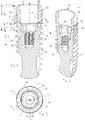
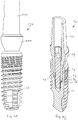
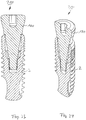
- FIG. 1 in a side cut and in FIG. 1 Dental implant 2 shown in a perspective section has an essentially pure titanium Grade 4 existing implant body 8 with an external thread 10.
- Other preferred materials are, for example, titanium grade 5 or titanium alloys.
- the dental implant 2 has a receiving opening for receiving an abutment.
- the receiving opening 20 has a cone section 26 which is rotationally symmetrical about a central axis M and an indexing section 32 which is essentially connected to form a step 28.
- a screw thread 38 which is designed as an internal screw thread and serves to receive a fixing screw, through which an abutment can be screwed to the implant.
- the dental implant 2 is designed to deflect the forces acting on the abutment or the artificial tooth replacement, which is attached to the abutment, which arise in particular through chewing, grinding and biting movements, as evenly and deeply as possible into the implant. At the same time, a deep conical connection with a tendency to cold welding is combined with a rotation-proof connection.
- a cone angle ⁇ of the cone section 26 (ie the angle between an imaginary line parallel to the central axis of the dental implant 2 and an imaginary line through the outer surface of the implant) is 1.4 °, so that the cone section 26 is thus designed as a Morse cone.
- the cone angle ⁇ corresponds to half of the so-called total cone angle.
- Such a steeply shaped cone allows a comparatively long conical section in which the abutment and implant enter into a form-fitting as well as a force-fitting connection. Due to the large contact area, forces from the abutment can be transmitted deep into the implant. Due to the subsequent rotationally secured part, forces can be introduced even more deeply, and torsional forces can also be absorbed there. Overall, a very deep power transfer is possible.
- the cone section 26 has a cone length l k of 3 mm.
- the radius of the cone section 26 tapers in a transition section 34 adjoining the indexing section 32 in the manner of a convex contour. This radially tapering region forms the rounded step 28 between the cone section 26 and the indexing section 32.
- An indexing length l i which indicates the length of the indexing section 32, is 1 mm, so that a total length l g , the sum of the cone length l k and the indexing length l i , 4 mm.
- the screw thread 38 has a screw thread length l s of 2.3 mm.
- the indexing section 32 is in a cross section in FIG. 3rd shown.
- Four grooves 56 are arranged along a circumference 50 in a configuration which is pronounced of the "Swiss cross".
- Each of the four grooves has side faces 62, which are each perpendicular to a common end face 68.
- the side surfaces 62 preferably have - in the direction of the central axis M - a length l f of 0.8 mm to 1.5 mm, in particular and in the present exemplary embodiment 1 mm.
- the length l f corresponds to the length l i of the indexing section 32.
- An end face width a is preferably 0.7 mm to 1.0 mm depending on the interface diameter, and the depth of the grooves or side face depth b is preferably 0.1 mm depending on the interface diameter up to 0.4 mm.
- the length l f is 1.0 mm
- the end face width a is 1.0 mm
- the side face depth b is 0.30 mm.
- the indexing section 32 comprises, as it were, four parallel-walled prisms arranged along the circumference 50, each of which is 1 mm high in the axial direction.
- the grooves 56 extend over the entire indexing length l i .
- Such a configuration is suitable for the highest torques and shows no tendency to cold welding, provided an abutment or screwing-in tool is used which has a shape-conforming outer contour, ie which has four cams arranged on a circumference, which can be brought into engagement in the grooves 56.
- This interface is also minimal Rotation game given.
- the interface between the implant and the abutment is designed as a groove-cam connection.
- a support surface 74 for an abutment is formed as seen from the coronal end 14 of the dental implant 2.
- An abutment which has an outer contour with four cams that is congruent to the inner shape of the indexing area 32, can first be placed on the support surface 74 before it is pushed into the dental implant 2 for final fixing.
- the desired orientation of the abutment can be found by turning the abutment clockwise or counterclockwise. As soon as this has been found, the abutment can then be pushed into the implant.
- An intermediate or intermediate position is defined by the contact surface 74 when the abutment is inserted.
- the side surfaces 62 and the end surface 68 serve as guide surfaces for the abutment when inserted.
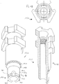
- FIG. 4th An abutment 80 in a first preferred embodiment is shown in FIG. 4th shown in perspective and has a cone section 86 and an indexing section 92.
- the cone section 86 has a cone angle ⁇ which corresponds to the cone angle ⁇ of the dental implant 2.
- the indexing section 92 of the abutment 80 has four cams 98 designed as parallel-walled prisms, which can be brought into engagement with the grooves 56 of the dental implant 2 in the assembled state, as a result of which a rotationally secured connection between the dental implant 2 and the abutment 80 is established by positive locking.
- the abutment 80 has a functional part 100 in a coronal area for fastening artificial dentures, in particular for cementing a crown.
- the cams 98 have a contour which is congruent in shape with the grooves 56 of the dental implant 2.
- the cams 98 each have one end face 106 and two side faces 108 perpendicular thereto and are arranged along an imaginary circumference.
- the abutment 80 has a gingiva section 104 which has an emergence profile for shaping the gingiva.
- a cross section through the abutment 80 is shown in FIG FIG. 6 shown.
- the abutment 80 has an internal thread 114 or internal screw thread for inserting a special tool. This makes it possible to detach the abutment 80 from a dental implant 2 again, even if the two cone sections 26, 86 are already cold-welded to one another.
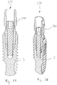
- FIG. 7 An abutment 80 that is not part of the invention is shown in FIG FIG. 7 shown in perspective.
- the abutment 80 according to FIG. 7 in contrast to the abutment 80 according to FIG. 4th no indexing section. Instead, it comprises a cylindrical guide section 112.
- An outer diameter u is dimensioned such that it corresponds to the diameter of the circumference 50 of the dental implant 2.
- the guide section 112 serves only to guide the abutment 80 while it is being lowered into the dental implant 2. This does not result in indexing.
- the attending doctor or dental technician can thus freely choose the alignment of the abutment 80 with respect to the dental implant 2 during the insertion process.
- FIG. 7 An abutment 80 that is not part of the invention is shown in perspective.
- the abutment 80 according to FIG. 7 in contrast to the abutment 80 according to FIG. 4th no indexing section. Instead, it comprises a cylindrical guide section 112.
- An outer diameter u is dimensioned such that it corresponds to
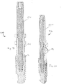
- FIG. 9 and 10 show an implant system 126 in a first preferred embodiment with a dental implant 2 shown above and an abutment 80 according to FIG FIG. 7 and 8 , which has a guide section 112 instead of an indexing section.
- the abutment 80 is completely inserted into the dental implant 2 and can be pressed onto the crown by firmly biting the patient or screwed in with a fixing screw (not shown).
- the FIG. 11 and 12 show an implant system 126 in a second preferred embodiment, in which the abutment 80, which in the FIG. 4, 5 and 6 is shown, comprises an indexing section 92 with four cams 98, so that result in four different orientations in the indexing section 32 of the dental implant 32.
- the impression post 150 shown in a first preferred embodiment has a conical insertion section 152 which is inserted into the cone section 26 of the dental implant 2 during the molding process.
- This special impression post 150 several implants or dental implants 2 which are also strongly divergent or skewed among one another can be molded. These implants are grouped together in the dental reconstruction and thus blocked together. Because of the blocking, the position and location of the index of the implants is not necessary.
- the connection design starts from the support shoulder with a short (0.3 mm long) cone 151, the angle of which follows the cone angle of the dental implant 2. This is followed by another cone 155, the angle of which is considerably larger. An angle of 25 ° to 35 ° has proven to be particularly advantageous.
- the flat cone 155 makes it easier to pull off the impression tray by means of a common pulling direction, and accordingly offers sufficient possibilities for pulling angled insertion posts out of the implants without the impression material being deformed appreciably.
- the impression post 150 shown in a second preferred embodiment has an indexing section 158, which adjoins an insertion section formed as a cylindrical transition region 153, with four cams 162, which can be brought into engagement with the grooves 56 of the dental implant in order to form a positive connection, so that the orientation or indexing of the implant in the human jaw can be transferred to a (master) model.
- the connection design starts from the support shoulder with a short (0.3 mm long) cone 151, the angle of which follows the cone angle of the implant. This is followed by another cone 155, the angle of which is considerably larger. An angle of 25 ° to 35 ° has proven to be particularly advantageous.
- the second cone opens into a cylindrical transition region 153, which represents the transition to the indexing region 158.
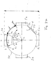
- FIG. 27th the cross section of the dental implant 2 is shown schematically.
- Four grooves 56 are arranged along the circumference 50.
- the radius of the circle defining the circumference 50 is denoted by r.
- the respective groove 56 has two points of contact p 1 , p 2 with the circumference 50.
- the section of the circle lying between these points of contact p 1 , p 2 or the angle that passes over it is a slot angle ⁇ or opening angle, the correspondingly swept slot arc length of the circle is c.
- a section of the circumference 50, the free arc length of which is designated by d is swept, an associated clearance angle being designated by ⁇ .
- the groove angle ⁇ or the opening angle is the angle between two m p through the center of the circular circumference 50 defining circuit and the contact points 1, p 2 extending imaginary lines L 1 and L2.
- the units of ⁇ and ⁇ degrees (°), c and d are each expressed as arc lengths.
- the ratio of clearance angle to slot angle, i.e. ⁇ / ⁇ or d / c, is in FIG. 1 ff. shown dental implant 2 0.61.
- a ratio in the range of 0.61 and 0.84 is particularly advantageous since the ratio of the depth of the grooves or side surface b and the total spacing of the grooves to one another is mechanically favorable. Due to the relatively wide end face width a, the side face depth b increases proportionally. The side surface depth b should be as large as possible to transmit the necessary screw-in torques and to avoid cold welding. On the other hand, the total spacing of the grooves e should be as little as possible, so that the cross-sectional area of the implant body and the area moment of inertia is as large as possible under bending and torsional loads.
- the enclosed cavity or volume f namely the cavity of the intermediate index area, which is spanned by the area between an arc length of the circumference of the circle between two grooves, which is delimited by a contact point p 2 of a groove and the Point of contact p 1 of an adjacent groove, and a secant s running through these two points, and a line perpendicular thereto with the side surface length l f .
Claims (10)
- Implant dentaire (2) à implanter dans un os maxillaire et ayant une ouverture de réception (20) pour une butée, disposée à l'extrémité coronale (14) de l'implant dentaire (2), l'ouverture de réception (20), vue de l'extrémité coronale (14), présentant une section conique (26) et une section d'indexation (32), la section d'indexation (32) présentant au moins une rainure (56) disposée le long d'une circonférence (50), s'étendant vers l'extérieur, la section conique (26) présentant un angle du cône (α) inférieur à 3°,
caractérisé en ce que
la rainure respective (56) est formée en tant que prisme aux plans parallèles et présente deux faces latérales (62), chacune perpendiculaire à une face frontale (68) commune disposée perpendiculairement sur une ligne non matérialisée s'étendant radialement à partir d'un axe central (M) de l'implant dentaire (2), un nombre exact de quatre rainures (56) étant disposé à des intervalles réguliers le long de la circonférence (50) et le rapport entre un angle libre (δ) le long duquel aucune rainure (56) n'est disposée sur la zone balayée sur la circonférence (50), et un angle de rainure (y), le long duquel une rainure (56) est disposée sur la zone balayée par la circonférence, est entre 1,0 et 0,5, notamment entre 0,61 et 0,84. - Implant dentaire (2) selon la revendication 1, l'angle du cône (α) étant entre 1° et 2°, notamment 1,4°.
- Implant dentaire (2) selon la revendication 1 ou 2, les faces latérales (62) présentant une longueur de 0,8 mm à 1,5 mm, notamment d'1 mm.
- Implant dentaire (2) selon l'une des revendications 1 à 3, une surface d'appui (74) circulaire permettant de faciliter l'enfilage pour une butée est formée à la section d'indexation (32).
- Implant dentaire (2) selon l'une des revendications 1 à 4, un filetage intérieur (38) prolonge la section d'indexation (32), vu de l'extrémité coronale (14).
- Butée (80) à implanter dans un implant dentaire (2) selon l'une des revendications 1 à 5 ayant une section conique (86) et une section d'indexation (92), la section conique (86) présentant un angle de cône (a) inférieur à 3° et la section d'indexation (92) présentant un nombre précis de quatre rainures (98) disposées à des intervalles réguliers le long d'une circonférence (110) pouvant s'engrener dans les rainures (56) épousant la forme de l'implant dentaire (2) selon l'une des revendications 1 à 5.
- Système d'implants (126), comprenant un implant dentaire (2) selon l'une des revendications 1 à 5 et une butée (80) selon la revendication 6, les sections coniques (26, 86) étant dimensionnées de sorte à ce qu'elles se contactent au moins partiellement et forment notamment une connexion autobloquante en état assemblé.
- Système d'implants (126) selon la revendication 7, la butée (80) présentant en lieu et place de la section d'indexation (92) une section cylindrique de guidage (112) implantable dans la section d'indexation (32) de l'implant dentaire (2).
- Système d'implants (126) selon la revendication 7 ou 8, un canal de passage pour le passage d'une vis de fixation étant prévu dans la butée (80).
- Jeu d'implantation (210) présentant au moins un implant dentaire (2) selon l'une des revendications 1 à 5 et au moins un élément auxiliaire du groupe : montants de moulage (150), mouleur des gencives (180), montant d'engagement (240).
Priority Applications (5)
| Application Number | Priority Date | Filing Date | Title |
|---|---|---|---|
| HUE13178279A HUE050729T2 (hu) | 2013-07-26 | 2013-07-26 | Fogászati implantátum, felépítmény, implantátum rendszer és implantációs készlet |
| ES13178279T ES2809470T3 (es) | 2013-07-26 | 2013-07-26 | Implante dental, pilar, sistema de implante y juego de implantación |
| PT131782799T PT2829250T (pt) | 2013-07-26 | 2013-07-26 | Implante dentário, pilar, sistema de implante e conjunto de implantação |
| EP13178279.9A EP2829250B1 (fr) | 2013-07-26 | 2013-07-26 | Implant dentaire, butée, système d'implant et jeu d'implantation |
| US14/341,237 US10695149B2 (en) | 2013-07-26 | 2014-07-25 | Dental implant, abutment, implant system and implant set |
Applications Claiming Priority (1)
| Application Number | Priority Date | Filing Date | Title |
|---|---|---|---|
| EP13178279.9A EP2829250B1 (fr) | 2013-07-26 | 2013-07-26 | Implant dentaire, butée, système d'implant et jeu d'implantation |
Publications (2)
| Publication Number | Publication Date |
|---|---|
| EP2829250A1 EP2829250A1 (fr) | 2015-01-28 |
| EP2829250B1 true EP2829250B1 (fr) | 2020-05-13 |
Family
ID=48874216
Family Applications (1)
| Application Number | Title | Priority Date | Filing Date |
|---|---|---|---|
| EP13178279.9A Active EP2829250B1 (fr) | 2013-07-26 | 2013-07-26 | Implant dentaire, butée, système d'implant et jeu d'implantation |
Country Status (5)
| Country | Link |
|---|---|
| US (1) | US10695149B2 (fr) |
| EP (1) | EP2829250B1 (fr) |
| ES (1) | ES2809470T3 (fr) |
| HU (1) | HUE050729T2 (fr) |
| PT (1) | PT2829250T (fr) |
Families Citing this family (11)
| Publication number | Priority date | Publication date | Assignee | Title |
|---|---|---|---|---|
| EP3095409A1 (fr) * | 2015-05-21 | 2016-11-23 | Epiphanostics GmbH | Kit d'insertion pour un implant unitaire endo-osseux |
| US11490997B2 (en) | 2015-07-24 | 2022-11-08 | Nobel Biocare Services Ag | Adapter for attaching a dental superstructure to a dental implant and dental assembly comprising the adapter |
| DE102015114449A1 (de) * | 2015-08-31 | 2017-03-02 | Jochen Rosbach | Gingivaformer |
| DE102015118285A1 (de) * | 2015-10-27 | 2017-04-27 | Heraeus Kulzer Gmbh | Scanabutment mit vergrößerter Scanfläche zur genaueren Höhenbestimmung der Implantatauflagefläche |
| GB2547191B (en) * | 2016-02-05 | 2020-01-08 | Advanced Risc Mach Ltd | An apparatus and method for supporting multiple cache features |
| ITUA20161638A1 (it) * | 2016-03-14 | 2017-09-14 | Sweden & Martina Spa | Sistema migliorato di impianto dentale |
| US10449019B2 (en) | 2016-07-20 | 2019-10-22 | Natural Dental Implants Ag | Systems and methods for securing a dental implant |
| IT201700068034A1 (it) * | 2017-06-19 | 2018-12-19 | Plan 1 Health Srl | Impianto dentale endosseo |
| JP7450540B2 (ja) * | 2017-12-22 | 2024-03-15 | イーロス メドゥテック ピノール アー/エス | デンタルインプラントアナログ |
| DE102017012134B3 (de) | 2017-12-28 | 2019-03-07 | Ljubinko Petrovic | Knochen-Implantat mit einem Verankerungsteil aus einem biokompatiblen Kunststoff |
| IT201800009288A1 (it) * | 2018-10-09 | 2020-04-09 | Ennio Calabria | Sistema di impianto dentale |
Citations (1)
| Publication number | Priority date | Publication date | Assignee | Title |
|---|---|---|---|---|
| EP2570097A1 (fr) * | 2011-09-14 | 2013-03-20 | Dentsply IH AB | Composant dentaire, fixation dentaire et implant dentaire |
Family Cites Families (23)
| Publication number | Priority date | Publication date | Assignee | Title |
|---|---|---|---|---|
| USRE38945E1 (en) * | 1995-01-30 | 2006-01-24 | Paula S. Fried | Dental implants and methods for extending service life |
| US6672871B2 (en) * | 2000-06-19 | 2004-01-06 | Nobel Biocare Ab | Coping with standoffs |
| GB0108551D0 (en) * | 2001-04-05 | 2001-05-23 | Osseobiotek Ltd | Implant |
| EP1728486A1 (fr) * | 2005-06-03 | 2006-12-06 | Straumann Holding AG | Connexion pour un système d'implant dentaire à plusieurs parties |
| EP2046238B1 (fr) * | 2006-08-01 | 2015-06-17 | BONDAR, Vitali | Système d'implant dentaire |
| US9095397B2 (en) * | 2006-12-14 | 2015-08-04 | Friadent Gmbh | Arrangement for insertion of implants |
| US8828066B2 (en) * | 2007-02-01 | 2014-09-09 | Sargon Lazarof | Securing mechanism with dual expandable ends |
| US8038442B2 (en) * | 2007-04-23 | 2011-10-18 | Nobel Biocare Services Ag | Dental implant and dental component connection |
| CA2699030A1 (fr) * | 2007-09-12 | 2009-03-19 | Vitali Bondar | Butee d'implant de capture et son procede |
| US20090111072A1 (en) * | 2007-10-30 | 2009-04-30 | Alan Lombardo | Dental implant and abutment mating system |
| US9055988B2 (en) * | 2007-11-09 | 2015-06-16 | Southern Implants (Pty) Ltd. | Dental implant adaptor |
| CN201160908Y (zh) * | 2008-03-12 | 2008-12-10 | 威海威高生物技术有限公司 | 口腔种植体装置 |
| US8029284B2 (en) * | 2008-09-29 | 2011-10-04 | Maxillent Ltd. | Implants, tools, and methods for sinus lift and lateral ridge augmentation |
| CN101732097A (zh) * | 2008-11-19 | 2010-06-16 | 威海威高生物技术有限公司 | 圆锥面加矩形键结构的口腔种植体 |
| EP2215989B8 (fr) * | 2009-02-05 | 2019-10-09 | Ivoclar Vivadent AG | Elément de montage pour un implant dentaire |
| EP2347729A1 (fr) * | 2010-01-21 | 2011-07-27 | Camlog Biotechnologies AG | Implant dentaire, butée pour un implant dentaire et combinaison des deux ainsi qu'un kit d'implantation |
| US20120077151A1 (en) * | 2010-09-24 | 2012-03-29 | Nary Filho Hugo | Morse Taper Dental Implant |
| CA2764079A1 (fr) * | 2011-01-20 | 2012-07-20 | Straumann Holding Ag | Ensemble d'implant dentaire et outil d'insertion |
| WO2012115969A2 (fr) * | 2011-02-21 | 2012-08-30 | Aeton Medical Llc | Butée et systèmes de butée à utiliser avec des implants |
| FR2972625B1 (fr) * | 2011-03-15 | 2014-02-28 | Biotech Internat | Implant dentaire |
| EP2514390B1 (fr) * | 2011-04-20 | 2023-12-13 | Dentsply IH AB | Ensemble de composants dentaires |
| EP2736446B1 (fr) * | 2011-07-27 | 2020-09-02 | Abracadabra Implants Ltd | Assemblage de restauration prosthodontique |
| US8684735B2 (en) * | 2011-12-06 | 2014-04-01 | Straumann Holding Ag | Abutment inlay |
-
2013
- 2013-07-26 ES ES13178279T patent/ES2809470T3/es active Active
- 2013-07-26 HU HUE13178279A patent/HUE050729T2/hu unknown
- 2013-07-26 EP EP13178279.9A patent/EP2829250B1/fr active Active
- 2013-07-26 PT PT131782799T patent/PT2829250T/pt unknown
-
2014
- 2014-07-25 US US14/341,237 patent/US10695149B2/en active Active
Patent Citations (1)
| Publication number | Priority date | Publication date | Assignee | Title |
|---|---|---|---|---|
| EP2570097A1 (fr) * | 2011-09-14 | 2013-03-20 | Dentsply IH AB | Composant dentaire, fixation dentaire et implant dentaire |
Also Published As
| Publication number | Publication date |
|---|---|
| US10695149B2 (en) | 2020-06-30 |
| HUE050729T2 (hu) | 2021-01-28 |
| PT2829250T (pt) | 2020-08-20 |
| US20150030993A1 (en) | 2015-01-29 |
| ES2809470T3 (es) | 2021-03-04 |
| EP2829250A1 (fr) | 2015-01-28 |
Similar Documents
| Publication | Publication Date | Title |
|---|---|---|
| EP2829250B1 (fr) | Implant dentaire, butée, système d'implant et jeu d'implantation | |
| EP2667820B1 (fr) | Système de prothèse dentaire | |
| EP3248566B1 (fr) | Pilier pour un implant dentaire, partie de tige pour un implant dentaire et implant dentaire | |
| EP1843717B1 (fr) | Implant dentaire | |
| EP3143961B1 (fr) | Implant dentaire | |
| EP3496653B1 (fr) | Implant dentaire comportant un corps de manchon et ensemble de pièces associé | |
| EP1734886B1 (fr) | Implant dentaire avec deux elements implant | |
| EP3082640B1 (fr) | Implant dentaire individuel placé à l'intérieur d'un os | |
| EP2852350B2 (fr) | Insert de rétention et dispositif de liaison pour applications dentaires | |
| EP2674127B1 (fr) | Implant | |
| EP1190682B1 (fr) | Cheville d'ancrage pour une pièce moulée dentaire | |
| EP3685795B1 (fr) | Implant unitaire endo-osseux | |
| DE102009027044B4 (de) | Mehrteiliges Zahnimplantat | |
| EP2724686B1 (fr) | Implant dentaire et système d'implant dentaire | |
| DE102008028132A1 (de) | Mehrteiliges Zahnimplantatsystem | |
| DE202010015755U1 (de) | Dentalimplantatsystem | |
| EP3666224A1 (fr) | Prothèse dentaire pourvue de manchon de raccordement | |
| WO2023222917A1 (fr) | Système d'implant | |
| WO2023242739A1 (fr) | Système de connecteur pour implant dentaire | |
| EP3595573A1 (fr) | Élément secondaire pour un implant dentaire et ensemble d'implant dentaire | |
| DE102016014348A1 (de) | Implantatpfosten und Implantatsystem | |
| DE102016000167A1 (de) | Zahnimplantat mit einem Mehrfachgewinde | |
| EP3275395A1 (fr) | Implant de vis dentaire ayant une approche axiale applicable par des os |
Legal Events
| Date | Code | Title | Description |
|---|---|---|---|
| 17P | Request for examination filed |
Effective date: 20130726 |
|
| AK | Designated contracting states |
Kind code of ref document: A1 Designated state(s): AL AT BE BG CH CY CZ DE DK EE ES FI FR GB GR HR HU IE IS IT LI LT LU LV MC MK MT NL NO PL PT RO RS SE SI SK SM TR |
|
| AX | Request for extension of the european patent |
Extension state: BA ME |
|
| PUAI | Public reference made under article 153(3) epc to a published international application that has entered the european phase |
Free format text: ORIGINAL CODE: 0009012 |
|
| R17P | Request for examination filed (corrected) |
Effective date: 20150728 |
|
| RBV | Designated contracting states (corrected) |
Designated state(s): AL AT BE BG CH CY CZ DE DK EE ES FI FR GB GR HR HU IE IS IT LI LT LU LV MC MK MT NL NO PL PT RO RS SE SI SK SM TR |
|
| STAA | Information on the status of an ep patent application or granted ep patent |
Free format text: STATUS: EXAMINATION IS IN PROGRESS |
|
| 17Q | First examination report despatched |
Effective date: 20190524 |
|
| GRAP | Despatch of communication of intention to grant a patent |
Free format text: ORIGINAL CODE: EPIDOSNIGR1 |
|
| STAA | Information on the status of an ep patent application or granted ep patent |
Free format text: STATUS: GRANT OF PATENT IS INTENDED |
|
| INTG | Intention to grant announced |
Effective date: 20191204 |
|
| GRAS | Grant fee paid |
Free format text: ORIGINAL CODE: EPIDOSNIGR3 |
|
| GRAA | (expected) grant |
Free format text: ORIGINAL CODE: 0009210 |
|
| STAA | Information on the status of an ep patent application or granted ep patent |
Free format text: STATUS: THE PATENT HAS BEEN GRANTED |
|
| AK | Designated contracting states |
Kind code of ref document: B1 Designated state(s): AL AT BE BG CH CY CZ DE DK EE ES FI FR GB GR HR HU IE IS IT LI LT LU LV MC MK MT NL NO PL PT RO RS SE SI SK SM TR |
|
| REG | Reference to a national code |
Ref country code: GB Ref legal event code: FG4D Free format text: NOT ENGLISH |
|
| REG | Reference to a national code |
Ref country code: CH Ref legal event code: EP |
|
| REG | Reference to a national code |
Ref country code: DE Ref legal event code: R096 Ref document number: 502013014705 Country of ref document: DE |
|
| REG | Reference to a national code |
Ref country code: AT Ref legal event code: REF Ref document number: 1269249 Country of ref document: AT Kind code of ref document: T Effective date: 20200615 |
|
| REG | Reference to a national code |
Ref country code: PT Ref legal event code: SC4A Ref document number: 2829250 Country of ref document: PT Date of ref document: 20200820 Kind code of ref document: T Free format text: AVAILABILITY OF NATIONAL TRANSLATION Effective date: 20200806 |
|
| REG | Reference to a national code |
Ref country code: LT Ref legal event code: MG4D |
|
| REG | Reference to a national code |
Ref country code: NL Ref legal event code: MP Effective date: 20200513 |
|
| PG25 | Lapsed in a contracting state [announced via postgrant information from national office to epo] |
Ref country code: IS Free format text: LAPSE BECAUSE OF FAILURE TO SUBMIT A TRANSLATION OF THE DESCRIPTION OR TO PAY THE FEE WITHIN THE PRESCRIBED TIME-LIMIT Effective date: 20200913 Ref country code: NO Free format text: LAPSE BECAUSE OF FAILURE TO SUBMIT A TRANSLATION OF THE DESCRIPTION OR TO PAY THE FEE WITHIN THE PRESCRIBED TIME-LIMIT Effective date: 20200813 Ref country code: SE Free format text: LAPSE BECAUSE OF FAILURE TO SUBMIT A TRANSLATION OF THE DESCRIPTION OR TO PAY THE FEE WITHIN THE PRESCRIBED TIME-LIMIT Effective date: 20200513 Ref country code: FI Free format text: LAPSE BECAUSE OF FAILURE TO SUBMIT A TRANSLATION OF THE DESCRIPTION OR TO PAY THE FEE WITHIN THE PRESCRIBED TIME-LIMIT Effective date: 20200513 Ref country code: GR Free format text: LAPSE BECAUSE OF FAILURE TO SUBMIT A TRANSLATION OF THE DESCRIPTION OR TO PAY THE FEE WITHIN THE PRESCRIBED TIME-LIMIT Effective date: 20200814 Ref country code: LT Free format text: LAPSE BECAUSE OF FAILURE TO SUBMIT A TRANSLATION OF THE DESCRIPTION OR TO PAY THE FEE WITHIN THE PRESCRIBED TIME-LIMIT Effective date: 20200513 |
|
| PG25 | Lapsed in a contracting state [announced via postgrant information from national office to epo] |
Ref country code: BG Free format text: LAPSE BECAUSE OF FAILURE TO SUBMIT A TRANSLATION OF THE DESCRIPTION OR TO PAY THE FEE WITHIN THE PRESCRIBED TIME-LIMIT Effective date: 20200813 Ref country code: RS Free format text: LAPSE BECAUSE OF FAILURE TO SUBMIT A TRANSLATION OF THE DESCRIPTION OR TO PAY THE FEE WITHIN THE PRESCRIBED TIME-LIMIT Effective date: 20200513 Ref country code: LV Free format text: LAPSE BECAUSE OF FAILURE TO SUBMIT A TRANSLATION OF THE DESCRIPTION OR TO PAY THE FEE WITHIN THE PRESCRIBED TIME-LIMIT Effective date: 20200513 Ref country code: HR Free format text: LAPSE BECAUSE OF FAILURE TO SUBMIT A TRANSLATION OF THE DESCRIPTION OR TO PAY THE FEE WITHIN THE PRESCRIBED TIME-LIMIT Effective date: 20200513 |
|
| PG25 | Lapsed in a contracting state [announced via postgrant information from national office to epo] |
Ref country code: AL Free format text: LAPSE BECAUSE OF FAILURE TO SUBMIT A TRANSLATION OF THE DESCRIPTION OR TO PAY THE FEE WITHIN THE PRESCRIBED TIME-LIMIT Effective date: 20200513 Ref country code: NL Free format text: LAPSE BECAUSE OF FAILURE TO SUBMIT A TRANSLATION OF THE DESCRIPTION OR TO PAY THE FEE WITHIN THE PRESCRIBED TIME-LIMIT Effective date: 20200513 |
|
| REG | Reference to a national code |
Ref country code: HU Ref legal event code: AG4A Ref document number: E050729 Country of ref document: HU |
|
| PG25 | Lapsed in a contracting state [announced via postgrant information from national office to epo] |
Ref country code: EE Free format text: LAPSE BECAUSE OF FAILURE TO SUBMIT A TRANSLATION OF THE DESCRIPTION OR TO PAY THE FEE WITHIN THE PRESCRIBED TIME-LIMIT Effective date: 20200513 Ref country code: SM Free format text: LAPSE BECAUSE OF FAILURE TO SUBMIT A TRANSLATION OF THE DESCRIPTION OR TO PAY THE FEE WITHIN THE PRESCRIBED TIME-LIMIT Effective date: 20200513 Ref country code: DK Free format text: LAPSE BECAUSE OF FAILURE TO SUBMIT A TRANSLATION OF THE DESCRIPTION OR TO PAY THE FEE WITHIN THE PRESCRIBED TIME-LIMIT Effective date: 20200513 Ref country code: CZ Free format text: LAPSE BECAUSE OF FAILURE TO SUBMIT A TRANSLATION OF THE DESCRIPTION OR TO PAY THE FEE WITHIN THE PRESCRIBED TIME-LIMIT Effective date: 20200513 Ref country code: RO Free format text: LAPSE BECAUSE OF FAILURE TO SUBMIT A TRANSLATION OF THE DESCRIPTION OR TO PAY THE FEE WITHIN THE PRESCRIBED TIME-LIMIT Effective date: 20200513 |
|
| REG | Reference to a national code |
Ref country code: DE Ref legal event code: R097 Ref document number: 502013014705 Country of ref document: DE |
|
| PG25 | Lapsed in a contracting state [announced via postgrant information from national office to epo] |
Ref country code: MC Free format text: LAPSE BECAUSE OF FAILURE TO SUBMIT A TRANSLATION OF THE DESCRIPTION OR TO PAY THE FEE WITHIN THE PRESCRIBED TIME-LIMIT Effective date: 20200513 Ref country code: PL Free format text: LAPSE BECAUSE OF FAILURE TO SUBMIT A TRANSLATION OF THE DESCRIPTION OR TO PAY THE FEE WITHIN THE PRESCRIBED TIME-LIMIT Effective date: 20200513 Ref country code: SK Free format text: LAPSE BECAUSE OF FAILURE TO SUBMIT A TRANSLATION OF THE DESCRIPTION OR TO PAY THE FEE WITHIN THE PRESCRIBED TIME-LIMIT Effective date: 20200513 |
|
| REG | Reference to a national code |
Ref country code: ES Ref legal event code: FG2A Ref document number: 2809470 Country of ref document: ES Kind code of ref document: T3 Effective date: 20210304 |
|
| PLBE | No opposition filed within time limit |
Free format text: ORIGINAL CODE: 0009261 |
|
| STAA | Information on the status of an ep patent application or granted ep patent |
Free format text: STATUS: NO OPPOSITION FILED WITHIN TIME LIMIT |
|
| 26N | No opposition filed |
Effective date: 20210216 |
|
| REG | Reference to a national code |
Ref country code: BE Ref legal event code: MM Effective date: 20200731 |
|
| PG25 | Lapsed in a contracting state [announced via postgrant information from national office to epo] |
Ref country code: LU Free format text: LAPSE BECAUSE OF NON-PAYMENT OF DUE FEES Effective date: 20200726 |
|
| PG25 | Lapsed in a contracting state [announced via postgrant information from national office to epo] |
Ref country code: BE Free format text: LAPSE BECAUSE OF NON-PAYMENT OF DUE FEES Effective date: 20200731 Ref country code: SI Free format text: LAPSE BECAUSE OF FAILURE TO SUBMIT A TRANSLATION OF THE DESCRIPTION OR TO PAY THE FEE WITHIN THE PRESCRIBED TIME-LIMIT Effective date: 20200513 |
|
| PG25 | Lapsed in a contracting state [announced via postgrant information from national office to epo] |
Ref country code: IE Free format text: LAPSE BECAUSE OF NON-PAYMENT OF DUE FEES Effective date: 20200726 |
|
| PG25 | Lapsed in a contracting state [announced via postgrant information from national office to epo] |
Ref country code: MT Free format text: LAPSE BECAUSE OF FAILURE TO SUBMIT A TRANSLATION OF THE DESCRIPTION OR TO PAY THE FEE WITHIN THE PRESCRIBED TIME-LIMIT Effective date: 20200513 Ref country code: CY Free format text: LAPSE BECAUSE OF FAILURE TO SUBMIT A TRANSLATION OF THE DESCRIPTION OR TO PAY THE FEE WITHIN THE PRESCRIBED TIME-LIMIT Effective date: 20200513 |
|
| PG25 | Lapsed in a contracting state [announced via postgrant information from national office to epo] |
Ref country code: MK Free format text: LAPSE BECAUSE OF FAILURE TO SUBMIT A TRANSLATION OF THE DESCRIPTION OR TO PAY THE FEE WITHIN THE PRESCRIBED TIME-LIMIT Effective date: 20200513 |
|
| PGFP | Annual fee paid to national office [announced via postgrant information from national office to epo] |
Ref country code: TR Payment date: 20220722 Year of fee payment: 10 |
|
| P01 | Opt-out of the competence of the unified patent court (upc) registered |
Effective date: 20230526 |
|
| PGFP | Annual fee paid to national office [announced via postgrant information from national office to epo] |
Ref country code: PT Payment date: 20230629 Year of fee payment: 11 |
|
| PGFP | Annual fee paid to national office [announced via postgrant information from national office to epo] |
Ref country code: IT Payment date: 20230731 Year of fee payment: 11 Ref country code: GB Payment date: 20230724 Year of fee payment: 11 Ref country code: ES Payment date: 20230821 Year of fee payment: 11 Ref country code: CH Payment date: 20230801 Year of fee payment: 11 Ref country code: AT Payment date: 20230718 Year of fee payment: 11 |
|
| PGFP | Annual fee paid to national office [announced via postgrant information from national office to epo] |
Ref country code: HU Payment date: 20230726 Year of fee payment: 11 Ref country code: FR Payment date: 20230724 Year of fee payment: 11 Ref country code: DE Payment date: 20230720 Year of fee payment: 11 |