EP2829250B1 - Dental implant, abutment, implant system and implantation set - Google Patents
Dental implant, abutment, implant system and implantation set Download PDFInfo
- Publication number
- EP2829250B1 EP2829250B1 EP13178279.9A EP13178279A EP2829250B1 EP 2829250 B1 EP2829250 B1 EP 2829250B1 EP 13178279 A EP13178279 A EP 13178279A EP 2829250 B1 EP2829250 B1 EP 2829250B1
- Authority
- EP
- European Patent Office
- Prior art keywords
- abutment
- section
- implant
- dental implant
- cone
- Prior art date
- Legal status (The legal status is an assumption and is not a legal conclusion. Google has not performed a legal analysis and makes no representation as to the accuracy of the status listed.)
- Active
Links
- 239000007943 implant Substances 0.000 title claims description 98
- 239000004053 dental implant Substances 0.000 title claims description 64
- 238000002513 implantation Methods 0.000 title claims description 14
- -1 abutment Substances 0.000 title 1
- 238000013461 design Methods 0.000 claims description 7
- 210000002050 maxilla Anatomy 0.000 claims 1
- 238000003466 welding Methods 0.000 description 17
- 238000003780 insertion Methods 0.000 description 13
- 230000037431 insertion Effects 0.000 description 13
- 210000000988 bone and bone Anatomy 0.000 description 8
- 210000004195 gingiva Anatomy 0.000 description 8
- 238000004519 manufacturing process Methods 0.000 description 7
- 230000007704 transition Effects 0.000 description 7
- 230000001055 chewing effect Effects 0.000 description 5
- 238000005516 engineering process Methods 0.000 description 5
- 241000894006 Bacteria Species 0.000 description 4
- 238000012546 transfer Methods 0.000 description 4
- 238000011109 contamination Methods 0.000 description 3
- 239000007788 liquid Substances 0.000 description 3
- 206010065687 Bone loss Diseases 0.000 description 2
- RTAQQCXQSZGOHL-UHFFFAOYSA-N Titanium Chemical compound [Ti] RTAQQCXQSZGOHL-UHFFFAOYSA-N 0.000 description 2
- 238000005452 bending Methods 0.000 description 2
- 230000005540 biological transmission Effects 0.000 description 2
- 238000010276 construction Methods 0.000 description 2
- 230000005489 elastic deformation Effects 0.000 description 2
- 230000002349 favourable effect Effects 0.000 description 2
- 238000000227 grinding Methods 0.000 description 2
- 230000014759 maintenance of location Effects 0.000 description 2
- 239000000463 material Substances 0.000 description 2
- 238000000034 method Methods 0.000 description 2
- 229910052719 titanium Inorganic materials 0.000 description 2
- 239000010936 titanium Substances 0.000 description 2
- 229910001069 Ti alloy Inorganic materials 0.000 description 1
- 230000015572 biosynthetic process Effects 0.000 description 1
- 230000000903 blocking effect Effects 0.000 description 1
- 230000037176 bone building Effects 0.000 description 1
- 230000007423 decrease Effects 0.000 description 1
- 210000004513 dentition Anatomy 0.000 description 1
- 230000001419 dependent effect Effects 0.000 description 1
- 238000006073 displacement reaction Methods 0.000 description 1
- 238000001125 extrusion Methods 0.000 description 1
- 238000000465 moulding Methods 0.000 description 1
- 230000035515 penetration Effects 0.000 description 1
- 238000007789 sealing Methods 0.000 description 1
- 238000007493 shaping process Methods 0.000 description 1
- 238000012360 testing method Methods 0.000 description 1
- 230000036346 tooth eruption Effects 0.000 description 1
Images


Classifications
-
- A—HUMAN NECESSITIES
- A61—MEDICAL OR VETERINARY SCIENCE; HYGIENE
- A61C—DENTISTRY; APPARATUS OR METHODS FOR ORAL OR DENTAL HYGIENE
- A61C8/00—Means to be fixed to the jaw-bone for consolidating natural teeth or for fixing dental prostheses thereon; Dental implants; Implanting tools
- A61C8/0048—Connecting the upper structure to the implant, e.g. bridging bars
- A61C8/005—Connecting devices for joining an upper structure with an implant member, e.g. spacers
- A61C8/0066—Connecting devices for joining an upper structure with an implant member, e.g. spacers with positioning means
-
- A—HUMAN NECESSITIES
- A61—MEDICAL OR VETERINARY SCIENCE; HYGIENE
- A61C—DENTISTRY; APPARATUS OR METHODS FOR ORAL OR DENTAL HYGIENE
- A61C8/00—Means to be fixed to the jaw-bone for consolidating natural teeth or for fixing dental prostheses thereon; Dental implants; Implanting tools
- A61C8/0001—Impression means for implants, e.g. impression coping
-
- A—HUMAN NECESSITIES
- A61—MEDICAL OR VETERINARY SCIENCE; HYGIENE
- A61C—DENTISTRY; APPARATUS OR METHODS FOR ORAL OR DENTAL HYGIENE
- A61C8/00—Means to be fixed to the jaw-bone for consolidating natural teeth or for fixing dental prostheses thereon; Dental implants; Implanting tools
- A61C8/0018—Means to be fixed to the jaw-bone for consolidating natural teeth or for fixing dental prostheses thereon; Dental implants; Implanting tools characterised by the shape
- A61C8/0022—Self-screwing
-
- A—HUMAN NECESSITIES
- A61—MEDICAL OR VETERINARY SCIENCE; HYGIENE
- A61C—DENTISTRY; APPARATUS OR METHODS FOR ORAL OR DENTAL HYGIENE
- A61C8/00—Means to be fixed to the jaw-bone for consolidating natural teeth or for fixing dental prostheses thereon; Dental implants; Implanting tools
- A61C8/0048—Connecting the upper structure to the implant, e.g. bridging bars
- A61C8/005—Connecting devices for joining an upper structure with an implant member, e.g. spacers
- A61C8/0068—Connecting devices for joining an upper structure with an implant member, e.g. spacers with an additional screw
-
- A—HUMAN NECESSITIES
- A61—MEDICAL OR VETERINARY SCIENCE; HYGIENE
- A61C—DENTISTRY; APPARATUS OR METHODS FOR ORAL OR DENTAL HYGIENE
- A61C8/00—Means to be fixed to the jaw-bone for consolidating natural teeth or for fixing dental prostheses thereon; Dental implants; Implanting tools
- A61C8/0048—Connecting the upper structure to the implant, e.g. bridging bars
- A61C8/005—Connecting devices for joining an upper structure with an implant member, e.g. spacers
- A61C8/0069—Connecting devices for joining an upper structure with an implant member, e.g. spacers tapered or conical connection
- A61C8/0071—Connecting devices for joining an upper structure with an implant member, e.g. spacers tapered or conical connection with a self-locking taper, e.g. morse taper
-
- A—HUMAN NECESSITIES
- A61—MEDICAL OR VETERINARY SCIENCE; HYGIENE
- A61C—DENTISTRY; APPARATUS OR METHODS FOR ORAL OR DENTAL HYGIENE
- A61C8/00—Means to be fixed to the jaw-bone for consolidating natural teeth or for fixing dental prostheses thereon; Dental implants; Implanting tools
- A61C8/008—Healing caps or the like
Definitions
- the invention relates to a dental implant for insertion into a jawbone, with a receiving opening for an abutment arranged at the coronal end of the implant, the receiving opening having a cone section and an indexing section, viewed from the coronal end, the indexing section being arranged at least one along a circumference has outwardly extending groove. It also concerns an abutment, an implant system and an implementation set.
- the impression of a complete dentition can be created optically.
- the lack of teeth can also lead to physical changes such as bone loss in the area of the jaw, displacements or "wandering" of the teeth still present in the direction of the gap that has arisen, or extrusion of the opposite teeth.
- a dental implant is used as an artificial denture, it is inserted into the resulting gap in the jawbone, in particular screwed in, where it grows as firmly as possible with the bone. An abutment is taken up by the implant, which then carries the visible dentures, such as a crown.
- the interface between the abutment and the implant is usually conical in a first section.
- a subsequent area secured against rotation for example an internal hexagon of the implant, which receives an external hexagon of the abutment to form a form-fitting connection, prevents the abutment from becoming worn over time by the Forces occurring in the mouth (particularly due to chewing movements) are rotated with respect to the implant. Indexing or indexing also facilitates precise transfer of the implant orientation to a master model and thus also the exact modeling and fitting of the denture.
- a dental implant which has a conical part and an adjoining indexing part.
- the total cone angle is 6 ° to 20 °.
- a disadvantage of an overall cone angle in this size range is that, on the one hand, only a relatively small clamping path is provided when lowering the abutment into the implant when taking the function, in particular when screwing tight.
- a flat angle reduces the frictional connection and thus the hold of the abutment due to the low surface pressure and possibly leads to a tilting of the abutment in relation to the implant.
- the invention is therefore based on the object of providing a dental implant which has high overall stability, reliability and service life.
- a corresponding abutment, an implant system and an implantation set are also to be provided.
- this object is achieved according to the invention by a dental implant according to claim 1.
- this object is achieved by an abutment according to claim 6.
- the invention is based on the consideration that the longevity and reliability of the dental implant are of crucial importance in the dental care of a patient with dentures. This is based on the overall stability of the system consisting of implant and abutment.
- the forces created in the mouth by chewing, grinding or biting movements are over transfer the abutment to the implant and from there into the bone. For this reason, the interfaces or transitions from abutment to implant and from implant to bone are particularly relevant for stability.
- the chewing forces introduced via the abutment, in particular thrust loads should be introduced as deeply as possible into the implant in the vertical direction.
- the dynamic elastic load on the bones should be kept as low as possible.
- a groove defines a preferred direction and an orientation. If several grooves are provided at a regular distance from one another, a multiple symmetry is defined. Due to the large cross-section and at least one groove, a large contact area is created, through which forces can be transmitted. This comparatively large contact area between the outer geometry of the abutment and the interior of the implant and the volume of the implant resulting from the cross section of the implant reduce the bulging of the implant body. This reduces the elastic deformation of the implant body, thereby reducing the load on the bone mentioned above.
- a now proposed design of the implant opens up the possibility of achieving a particularly strong permanent load-resistant connection to an abutment due to the self-locking or cold welding of the morse taper without additional connecting elements, such as a fixing screw, without having to make a defined selection indexing directions must be dispensed with.
- additional connecting elements such as a fixing screw
- the fixation of the abutment and implant can also be carried out or supported by a connecting element, whereby the permanent load resistance can be increased even further.
- Dental dental technology requires a high level of vertical precision in the manufacture of dental technology constructions, since the chewing planes in the human jaw are finely coordinated.
- these high requirements on vertical tolerance have often stood in the way of using the so-called Morse paper or Morse cone, since the conventional view was that this type of construction cannot be easily combined with a subsequent indexing part.
- the abutment in the conical section penetrates too deeply into the implant or sinks into it, it can bump into the end in the rotation-protected area, so that the desired cold welding does not occur in the cone area.
- insufficient penetration of the abutment into the rotation-protected area leads to insufficient security against rotation.
- implant denotes the component which is anchored directly in the bone and receives an abutment which is inserted into the implant and in particular screwed to it.
- the indexing section preferably adjoins the cone section as seen from the coronal end, in particular with the formation of a step.
- a conical or cylindrical intermediate section can also be provided, which can serve as a guide section, for example.
- the cone angle is between 1 ° and 3 °, in particular 1.4 °.
- Such a steep cone promotes the tendency to cold welding and thus to mechanically strengthen the connection between the abutment and the implant in the assembled state. This also results in a particularly high level of tightness against bacteria.
- the respective groove has two side faces, each of which is perpendicular to a common end face which is perpendicular to an imaginary line radially extending from an implant center axis.
- the grooves are designed as parallel-walled prisms, the side surfaces running essentially parallel to the central axis of the implant. If an abutment is inserted into the implant with at least one cam, which can be brought into engagement with the groove designed in this way, there is no thrust friction in the case of rotational counter-movements of the implant and abutment, as occurs, for example, if the interface consists of a hexagon socket of the implant and an external hexagon of the abutment which can be brought into a form fit therein. Due to the shape of the groove provided, when the abutment and implant are rotated relative to one another, the forces which arise are introduced essentially perpendicularly into the surfaces, so that deformations of the surfaces are avoided. With high applied torques and the pressure of the outer surfaces of the abutment against the inner surfaces of the implant, the tendency towards cold welding, which is undesired in this section, is greatly reduced due to the vertical and uniform introduction of the forces.
- exactly four grooves are arranged at regular intervals along the circumference.
- Such a design corresponds to the shape of the grooves to a certain extent to the "Swiss cross".
- the ratio of a clearance angle, along the area of which no groove is arranged on the circumference of the circle, and of a slot angle, along whose area of which the area is swept on the circumference is between 1.0 and 0.5, in particular between 0.61 and 0.84.
- a ratio of 1.0 means for the four grooves provided that the two angles of relief angle and groove angle are of the same size and thus the amounts of the respective circular circumference sections that are swept over or the corresponding arc length of this circular circumference section are of the same size. If the ratio is less than 1.0, the arc length of the circumference along a groove is greater than that without a groove. The smaller the ratio, the wider the grooves with the same circumference.
- a ratio in the range of 0.61 and 0.84 is particularly advantageous, since it means the ratio of the depth of the grooves or side surface and the total distance the grooves are mechanically favorable to each other. Due to the relatively large end face width, the side face increases proportionally. The side surface should be as large as possible to transmit the necessary screw-in torques and to avoid cold welding. On the other hand, the total spacing of the grooves should be as little as possible so that the cross-sectional area of the implant body and the area moment of inertia are as large as possible under bending and torsional loads.
- the enclosed cavity is reduced, which is the volume from the enclosed arc length of the circumference between two grooves and results in the connecting straight line between the surface of the abutment and the side surface length. This minimizes the possible contamination of the interior of the implant with liquids and bacteria.
- the ratio is less than 1.0, i.e. the arc length of the circumference along a groove is greater than that without a groove, which is advantageous for the design of the indexing section of the implant-abutment interface is.
- a circular contact surface to support the threading of an abutment is advantageously formed on the indexing section. This makes it easier for the doctor or dental technician to insert and fit the abutment, since the insertion and the orientation are two movements that can be carried out separately and one behind the other.
- the abutment can first be pushed into the implant until it rests on the contact surface. Thereafter, engagement with the grooves can be achieved by rotating the abutment in one direction or the other. The abutment is then pushed or pushed further into the implant in the orientation now defined.
- an internal screw thread connects to the indexing section in a preferred embodiment. This then takes a fixing screw to screw the abutment to the implant or to fix the abutment.
- an internal screw thread can also be dispensed with, so that the mechanical connection between the implant body and an abutment is only ensured by cold welding the contact surface of the morse taper.
- a permanent load-resistant connection can be achieved due to the selected cone angle solely due to the self-locking of the steep Morse cone.
- the implant therefore has no internal screw thread. However, it is not necessary to do without a defined indexing.
- the above-mentioned object is achieved according to the invention with an abutment for insertion into a dental implant, in particular a dental implant described above, with a cone section and an indexing section, the cone section having a cone angle of less than 3 °.
- the indexing section has a number of cams arranged on a circumference, which can be brought into engagement with grooves of a dental implant. Cams and grooves form a rotation-proof connection.
- the abutment can be inserted into the implant in a number of defined orientations, the orientations being determined by the fact that the cam (s) and groove (s) engage in each other to form a positive connection.
- cams are provided, which are arranged at regular intervals along a circumference.
- the cams have a rectangular contour that conforms to the circumference of the circle and are designed as primes that extend along a central axis of the abutment.
- an internal screw thread is advantageously provided in the area of the screw channel in the abutment.
- the abutment can be detached from the implant despite the cold welding in the conical area.
- the above-mentioned object is achieved according to the invention with an above-described dental implant and an above-described abutment, the conical sections of the dental implant and abutment being dimensioned such that they touch at least partially, in particular in the assembled state, they form a self-locking connection.
- the respective cone sections and indexing sections of the implant and abutment are advantageously dimensioned and matched to one another in their shape in such a way that the largest possible contact area is created in the conical part and at the same time the indexing sections overlap as far as possible.
- the cone angles for the implant and abutment are preferably identical in each case or largely correspond. Such a configuration is made possible by the smallest possible manufacturing tolerances of the internal or external geometry of the implant or abutment.
- the abutment has a cylindrical guide section instead of an indexing section, which can be inserted into the indexing section of the dental implant.
- this indexing section is only partially used by the abutment, namely not to define a defined indexing, but rather as a guiding area when inserting the abutment into the implant, which leads to strong strength when inserted.
- a through-channel for the passage of a fixing screw is preferably provided in the abutment. The fixing screw is in the inserted state through the abutment into the implant, where it is screwed into the internal screw thread of the implant. In such a configuration, the permanent connection of the two components is realized not only by cold welding the cone sections, but also by the screw used.
- the above-mentioned object is achieved with an above-mentioned dental implant and at least one auxiliary element from the group: impression post, gingiva former, insertion post.
- the implantation set further preferably comprises an abutment described above.
- the advantages of the invention lie in particular in that an implant and an implant system with a high degree of reliability and service life are created by connecting a morse taper to a subsequent indexing section and the resulting possibilities of deep introduction of forces acting on the abutment.
- the configuration of the cone section as a morse taper or morse taper enables a high level of self-locking due to frictional engagement and the tendency towards cold welding. This creates a positive and non-positive connection between the abutment and the implant. Due to the cold welding, maximum functional sealing against contamination is also realized. In particular with an implant interface that is anchored in the implant over a length of 4 mm, only minimal expansion and bulging of the contact surfaces should occur even under dynamic loading. This ensures maximum tightness against incoming liquids and bacteria.
- a particularly advantageous shape is realized by parallel-walled side surfaces of the grooves for securing against rotation with their orientation from 0 ° to initiated torques, in which there is no thrust friction, for example would result from an oblique force transmission in a hexagon. There is therefore no tendency that high torques when screwing the implant with high surface pressure onto the transfer surfaces lead to cold welding of the retention surfaces. This means that a desired cold welding can be implemented in a targeted manner in the cone part, while at the same time an undesired cold welding in the indexing part can be avoided.
- a circular contact surface adjoining the cone allows the abutment to be supported during insertion without it being possible for it to be jammed in an intermediate position.
- the treating dental technician or doctor can find the index of the interface by rotating the abutment in any direction. The abutment glides smoothly and almost automatically with the cams into the inner contour of the implant interface.
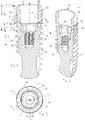
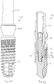
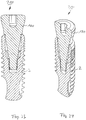
- FIG. 1 in a side cut and in FIG. 1 Dental implant 2 shown in a perspective section has an essentially pure titanium Grade 4 existing implant body 8 with an external thread 10.
- Other preferred materials are, for example, titanium grade 5 or titanium alloys.
- the dental implant 2 has a receiving opening for receiving an abutment.
- the receiving opening 20 has a cone section 26 which is rotationally symmetrical about a central axis M and an indexing section 32 which is essentially connected to form a step 28.
- a screw thread 38 which is designed as an internal screw thread and serves to receive a fixing screw, through which an abutment can be screwed to the implant.
- the dental implant 2 is designed to deflect the forces acting on the abutment or the artificial tooth replacement, which is attached to the abutment, which arise in particular through chewing, grinding and biting movements, as evenly and deeply as possible into the implant. At the same time, a deep conical connection with a tendency to cold welding is combined with a rotation-proof connection.
- a cone angle ⁇ of the cone section 26 (ie the angle between an imaginary line parallel to the central axis of the dental implant 2 and an imaginary line through the outer surface of the implant) is 1.4 °, so that the cone section 26 is thus designed as a Morse cone.
- the cone angle ⁇ corresponds to half of the so-called total cone angle.
- Such a steeply shaped cone allows a comparatively long conical section in which the abutment and implant enter into a form-fitting as well as a force-fitting connection. Due to the large contact area, forces from the abutment can be transmitted deep into the implant. Due to the subsequent rotationally secured part, forces can be introduced even more deeply, and torsional forces can also be absorbed there. Overall, a very deep power transfer is possible.
- the cone section 26 has a cone length l k of 3 mm.
- the radius of the cone section 26 tapers in a transition section 34 adjoining the indexing section 32 in the manner of a convex contour. This radially tapering region forms the rounded step 28 between the cone section 26 and the indexing section 32.
- An indexing length l i which indicates the length of the indexing section 32, is 1 mm, so that a total length l g , the sum of the cone length l k and the indexing length l i , 4 mm.
- the screw thread 38 has a screw thread length l s of 2.3 mm.
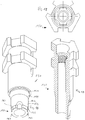
- the indexing section 32 is in a cross section in FIG. 3rd shown.
- Four grooves 56 are arranged along a circumference 50 in a configuration which is pronounced of the "Swiss cross".
- Each of the four grooves has side faces 62, which are each perpendicular to a common end face 68.
- the side surfaces 62 preferably have - in the direction of the central axis M - a length l f of 0.8 mm to 1.5 mm, in particular and in the present exemplary embodiment 1 mm.
- the length l f corresponds to the length l i of the indexing section 32.
- An end face width a is preferably 0.7 mm to 1.0 mm depending on the interface diameter, and the depth of the grooves or side face depth b is preferably 0.1 mm depending on the interface diameter up to 0.4 mm.
- the length l f is 1.0 mm
- the end face width a is 1.0 mm
- the side face depth b is 0.30 mm.
- the indexing section 32 comprises, as it were, four parallel-walled prisms arranged along the circumference 50, each of which is 1 mm high in the axial direction.
- the grooves 56 extend over the entire indexing length l i .
- Such a configuration is suitable for the highest torques and shows no tendency to cold welding, provided an abutment or screwing-in tool is used which has a shape-conforming outer contour, ie which has four cams arranged on a circumference, which can be brought into engagement in the grooves 56.
- This interface is also minimal Rotation game given.
- the interface between the implant and the abutment is designed as a groove-cam connection.
- a support surface 74 for an abutment is formed as seen from the coronal end 14 of the dental implant 2.
- An abutment which has an outer contour with four cams that is congruent to the inner shape of the indexing area 32, can first be placed on the support surface 74 before it is pushed into the dental implant 2 for final fixing.
- the desired orientation of the abutment can be found by turning the abutment clockwise or counterclockwise. As soon as this has been found, the abutment can then be pushed into the implant.
- An intermediate or intermediate position is defined by the contact surface 74 when the abutment is inserted.
- the side surfaces 62 and the end surface 68 serve as guide surfaces for the abutment when inserted.
- FIG. 4th An abutment 80 in a first preferred embodiment is shown in FIG. 4th shown in perspective and has a cone section 86 and an indexing section 92.
- the cone section 86 has a cone angle ⁇ which corresponds to the cone angle ⁇ of the dental implant 2.
- the indexing section 92 of the abutment 80 has four cams 98 designed as parallel-walled prisms, which can be brought into engagement with the grooves 56 of the dental implant 2 in the assembled state, as a result of which a rotationally secured connection between the dental implant 2 and the abutment 80 is established by positive locking.
- the abutment 80 has a functional part 100 in a coronal area for fastening artificial dentures, in particular for cementing a crown.
- the cams 98 have a contour which is congruent in shape with the grooves 56 of the dental implant 2.
- the cams 98 each have one end face 106 and two side faces 108 perpendicular thereto and are arranged along an imaginary circumference.
- the abutment 80 has a gingiva section 104 which has an emergence profile for shaping the gingiva.
- a cross section through the abutment 80 is shown in FIG FIG. 6 shown.
- the abutment 80 has an internal thread 114 or internal screw thread for inserting a special tool. This makes it possible to detach the abutment 80 from a dental implant 2 again, even if the two cone sections 26, 86 are already cold-welded to one another.
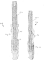
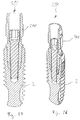
- FIG. 7 An abutment 80 that is not part of the invention is shown in FIG FIG. 7 shown in perspective.
- the abutment 80 according to FIG. 7 in contrast to the abutment 80 according to FIG. 4th no indexing section. Instead, it comprises a cylindrical guide section 112.
- An outer diameter u is dimensioned such that it corresponds to the diameter of the circumference 50 of the dental implant 2.
- the guide section 112 serves only to guide the abutment 80 while it is being lowered into the dental implant 2. This does not result in indexing.
- the attending doctor or dental technician can thus freely choose the alignment of the abutment 80 with respect to the dental implant 2 during the insertion process.
- FIG. 7 An abutment 80 that is not part of the invention is shown in perspective.
- the abutment 80 according to FIG. 7 in contrast to the abutment 80 according to FIG. 4th no indexing section. Instead, it comprises a cylindrical guide section 112.
- An outer diameter u is dimensioned such that it corresponds to
- FIG. 9 and 10 show an implant system 126 in a first preferred embodiment with a dental implant 2 shown above and an abutment 80 according to FIG FIG. 7 and 8 , which has a guide section 112 instead of an indexing section.
- the abutment 80 is completely inserted into the dental implant 2 and can be pressed onto the crown by firmly biting the patient or screwed in with a fixing screw (not shown).
- the FIG. 11 and 12 show an implant system 126 in a second preferred embodiment, in which the abutment 80, which in the FIG. 4, 5 and 6 is shown, comprises an indexing section 92 with four cams 98, so that result in four different orientations in the indexing section 32 of the dental implant 32.
- the impression post 150 shown in a first preferred embodiment has a conical insertion section 152 which is inserted into the cone section 26 of the dental implant 2 during the molding process.
- This special impression post 150 several implants or dental implants 2 which are also strongly divergent or skewed among one another can be molded. These implants are grouped together in the dental reconstruction and thus blocked together. Because of the blocking, the position and location of the index of the implants is not necessary.
- the connection design starts from the support shoulder with a short (0.3 mm long) cone 151, the angle of which follows the cone angle of the dental implant 2. This is followed by another cone 155, the angle of which is considerably larger. An angle of 25 ° to 35 ° has proven to be particularly advantageous.
- the flat cone 155 makes it easier to pull off the impression tray by means of a common pulling direction, and accordingly offers sufficient possibilities for pulling angled insertion posts out of the implants without the impression material being deformed appreciably.
- the impression post 150 shown in a second preferred embodiment has an indexing section 158, which adjoins an insertion section formed as a cylindrical transition region 153, with four cams 162, which can be brought into engagement with the grooves 56 of the dental implant in order to form a positive connection, so that the orientation or indexing of the implant in the human jaw can be transferred to a (master) model.
- the connection design starts from the support shoulder with a short (0.3 mm long) cone 151, the angle of which follows the cone angle of the implant. This is followed by another cone 155, the angle of which is considerably larger. An angle of 25 ° to 35 ° has proven to be particularly advantageous.
- the second cone opens into a cylindrical transition region 153, which represents the transition to the indexing region 158.
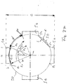
- FIG. 27th the cross section of the dental implant 2 is shown schematically.
- Four grooves 56 are arranged along the circumference 50.
- the radius of the circle defining the circumference 50 is denoted by r.
- the respective groove 56 has two points of contact p 1 , p 2 with the circumference 50.
- the section of the circle lying between these points of contact p 1 , p 2 or the angle that passes over it is a slot angle ⁇ or opening angle, the correspondingly swept slot arc length of the circle is c.
- a section of the circumference 50, the free arc length of which is designated by d is swept, an associated clearance angle being designated by ⁇ .
- the groove angle ⁇ or the opening angle is the angle between two m p through the center of the circular circumference 50 defining circuit and the contact points 1, p 2 extending imaginary lines L 1 and L2.
- the units of ⁇ and ⁇ degrees (°), c and d are each expressed as arc lengths.
- the ratio of clearance angle to slot angle, i.e. ⁇ / ⁇ or d / c, is in FIG. 1 ff. shown dental implant 2 0.61.
- a ratio in the range of 0.61 and 0.84 is particularly advantageous since the ratio of the depth of the grooves or side surface b and the total spacing of the grooves to one another is mechanically favorable. Due to the relatively wide end face width a, the side face depth b increases proportionally. The side surface depth b should be as large as possible to transmit the necessary screw-in torques and to avoid cold welding. On the other hand, the total spacing of the grooves e should be as little as possible, so that the cross-sectional area of the implant body and the area moment of inertia is as large as possible under bending and torsional loads.
- the enclosed cavity or volume f namely the cavity of the intermediate index area, which is spanned by the area between an arc length of the circumference of the circle between two grooves, which is delimited by a contact point p 2 of a groove and the Point of contact p 1 of an adjacent groove, and a secant s running through these two points, and a line perpendicular thereto with the side surface length l f .
Description
Die Erfindung betrifft ein Dentalimplantat zum Einsetzen in einen Kieferknochen, mit einer am koronalen Ende des Implantats angeordneten Aufnahmeöffnung für ein Abutment, wobei die Aufnahmeöffnung vom koronalen Ende her gesehen einen Konusabschnitt und einen Indexierungsabschnitt aufweist, wobei der Indexierungsabschnitt wenigstens eine entlang eines Kreisumfanges angeordnete, sich nach außen erstreckende Nut aufweist. Sie betrifft weiterhin ein Abutment, ein Implantatsystem und ein Implementationsset.The invention relates to a dental implant for insertion into a jawbone, with a receiving opening for an abutment arranged at the coronal end of the implant, the receiving opening having a cone section and an indexing section, viewed from the coronal end, the indexing section being arranged at least one along a circumference has outwardly extending groove. It also concerns an abutment, an implant system and an implementation set.
Die Versorgung eines Patienten mit künstlichem Zahnersatz, der anstelle des oder der vormals vorhandenen natürlichen Zähne tritt, hat gewöhnlich sowohl ästhetische als auch medizinische Hintergründe. Einerseits kann optisch der Eindruck eines vollständigen Gebisses hergestellt werden. Andererseits kann das Fehlen von Zähnen auch zu körperlichen Veränderungen wie Knochenabbau im Bereich des Kiefers, Verschiebungen bzw. "Wandern" der noch vorhandenen Zähne in Richtung der entstandenen Lücke, oder Extrudierungen der gegenüberliegenden Zähne führen.Providing a patient with artificial dentures to replace the natural tooth (s) that were previously present usually has both aesthetic and medical backgrounds. On the one hand, the impression of a complete dentition can be created optically. On the other hand, the lack of teeth can also lead to physical changes such as bone loss in the area of the jaw, displacements or "wandering" of the teeth still present in the direction of the gap that has arisen, or extrusion of the opposite teeth.
Wird als künstlicher Zahnersatz ein Dentalimplantat verwendet, wird dieses in der entstandenen Lücke in den Kieferknochen eingesetzt, insbesondere eingeschraubt, wo es möglichst fest mit dem Knochen verwächst. Von dem Implantat wird ein Abutment aufgenommen, welches dann den sichtbaren Zahnersatz, wie beispielsweise eine Krone, trägt.If a dental implant is used as an artificial denture, it is inserted into the resulting gap in the jawbone, in particular screwed in, where it grows as firmly as possible with the bone. An abutment is taken up by the implant, which then carries the visible dentures, such as a crown.
Die Schnittstelle zwischen Abutment und Implantat ist gewöhnlich in einem ersten Teil bzw. Teilabschnitt konisch ausgeführt. Ein sich daran anschließender rotationsgesicherter Bereich, beispielsweise ein Innensechskant des Implantats, der einen Außensechskant des Abutments zur Bildung einer formschlüssigen Verbindung aufnimmt, verhindert, dass sich das Abutment im Laufe der Zeit durch die im Mund auftretenden Kräfte (insbesondere aufgrund von Kaubewegungen) gegenüber dem Implantat verdreht. Eine Indizierung bzw. Indexierung erleichtert zudem eine präzise Übertragung der Implantatorientierung auf ein Meistermodell und somit auch die genaue Modellierung und Einpassung des Zahnersatzes.The interface between the abutment and the implant is usually conical in a first section. A subsequent area secured against rotation, for example an internal hexagon of the implant, which receives an external hexagon of the abutment to form a form-fitting connection, prevents the abutment from becoming worn over time by the Forces occurring in the mouth (particularly due to chewing movements) are rotated with respect to the implant. Indexing or indexing also facilitates precise transfer of the implant orientation to a master model and thus also the exact modeling and fitting of the denture.
Aus der
Nachteilig bei einem Gesamtkonuswinkel in diesem Größenbereich ist, dass zum einen nur ein relativ geringer Spannweg bei der Absenkung des Abutments in das Implantat bei der Infunktionsnahme, insbesondere beim festen Verschrauben, zur Verfügung gestellt wird. Zum anderen vermindert ein flacher Winkel aufgrund der geringen Flächenpressung den Kraftschluss und damit den Halt des Abutments und führt gegebenenfalls zu einer Abkippung des Abutments im Verhältnis zum Implantat.A disadvantage of an overall cone angle in this size range is that, on the one hand, only a relatively small clamping path is provided when lowering the abutment into the implant when taking the function, in particular when screwing tight. On the other hand, a flat angle reduces the frictional connection and thus the hold of the abutment due to the low surface pressure and possibly leads to a tilting of the abutment in relation to the implant.
Aus der
Der Erfindung liegt daher die Aufgabe zugrunde, ein Dentalimplantat bereitzustellen, welches eine hohe Gesamtstabilität, Zuverlässigkeit und Lebensdauer aufweist. Weiterhin sollen ein entsprechendes Abutment, ein Implantatsystem und ein Implantationsset bereitgestellt werden.The invention is therefore based on the object of providing a dental implant which has high overall stability, reliability and service life. A corresponding abutment, an implant system and an implantation set are also to be provided.
In Bezug auf das Implantat wird diese Aufgabe erfindungsgemäß durch ein Dentalimplantat gemäß Anspruch 1 gelöst. In Bezug auf das Abutment wird diese Aufgabe durch ein Abutment gemäß Anspruch 6 gelöst.With regard to the implant, this object is achieved according to the invention by a dental implant according to claim 1. With regard to the abutment, this object is achieved by an abutment according to claim 6.
Vorteilhafte Ausgestaltungen der Erfindung sind Gegenstand der Unteransprüche. Die Erfindung geht von der Überlegung aus, dass bei einer zahntechnischen Versorgung eines Patienten mit Zahnersatz die Langlebigkeit und Zuverlässigkeit des Dentalimplantates von entscheidender Bedeutung sind. Grundlegend dafür ist die Gesamtstabilität des Systems bestehend aus Implantat und Abutment. Die im Mund durch Kau-, Mahl oder Beißbewegungen entstehenden Kräfte werden über das Abutment an das Implantat und von dort in den Knochen übertragen. Aus diesem Grund sind für die Stabilität insbesondere auch die Schnittstellen bzw. Übergänge von Abutment zu Implantat und von Implantat zu Knochen relevant. Zur Erfüllung der oben genannten Anforderungen sollten die über das Abutment eingeleiteten Kaukräfte, insbesondere Schubbelastungen, in vertikaler Richtung möglichst tief in das Implantat eingeleitet werden. Zudem sollte die dynamische elastische Lasteinwirkung auf den Knochen möglichst gering gehalten werden.Advantageous embodiments of the invention are the subject of the dependent claims. The invention is based on the consideration that the longevity and reliability of the dental implant are of crucial importance in the dental care of a patient with dentures. This is based on the overall stability of the system consisting of implant and abutment. The forces created in the mouth by chewing, grinding or biting movements are over transfer the abutment to the implant and from there into the bone. For this reason, the interfaces or transitions from abutment to implant and from implant to bone are particularly relevant for stability. To meet the above-mentioned requirements, the chewing forces introduced via the abutment, in particular thrust loads, should be introduced as deeply as possible into the implant in the vertical direction. In addition, the dynamic elastic load on the bones should be kept as low as possible.
Die tiefe Übertragung von Schubbelastungen lässt sich mit einem eher flachen Konus nicht erreichen, da dieser aufgrund des vorgegebenen Implantataußendurchmessers nicht weit genug in vertikaler Richtung in das Implantat hinreicht. Wie aber nunmehr erkannt wurde, wird diese Aufgabe von einem steilen Konus mit Konuswinkeln im Bereich von 1° bis 3°, dem so genannten Morsekegel, erreicht. Der steile Winkel erlaubt bei vorgegebener Implantatlänge und Dicke die Realisierung einer vergleichsweise langen Schnittstelle. Durch einen sich an den steilen, konusförmigen Abschnitt anschließendes Indexierungs-bzw. Retentionsabschnitt können Kräfte noch tiefer in das Implantat eingeleitet werden. Der steile Winkel führt zudem zu einem gleichmäßigen und vergleichsweise langsamen Zuwachs der Implantatwandstärke. Daraus folgt, dass der Querschnitt mit steigender Tiefe vergleichsweise langsam abnimmt. Dadurch wird ein Retentionsabschnitt mit vergleichsweise großem Querschnitt ermöglicht, der naturgemäß nicht größer sein darf als der kleinste Durchmesser des Konusabschnittes, da ansonsten das Abutment nicht durchgeführt werden könnte.The deep transmission of shear loads cannot be achieved with a rather flat cone, because this does not reach far enough in the vertical direction into the implant due to the given implant outer diameter. However, as has now been recognized, this task is accomplished by a steep cone with cone angles in the range from 1 ° to 3 °, the so-called Morse cone. With a given implant length and thickness, the steep angle allows the realization of a comparatively long interface. By means of an indexing or subsequent to the steep, conical section. Forces can be introduced even deeper into the implant. The steep angle also leads to a steady and comparatively slow increase in the implant wall thickness. It follows that the cross section decreases comparatively slowly with increasing depth. This enables a retention section with a comparatively large cross section, which of course must not be larger than the smallest diameter of the cone section, since otherwise the abutment could not be carried out.
Eine Nut definiert eine Vorzugsrichtung und eine Ausrichtung. Sind mehrere Nuten in regelmäßigem Abstand voneinander vorgesehen, wird dadurch eine mehrzählige Symmetrie definiert. Durch den großen Querschnitt und wenigstens eine Nut entsteht eine große Kontaktfläche, über die Kräfte weitergeleitet werden können. Diese vergleichsweise große Kontaktfläche zwischen Abutmentaußen- und Implantatinnengeometrie und das sich über den Implantatquerschnitt ergebene Implantatvolumen reduzieren die Auswölbung des Implantatkörpers. Dadurch wird die elastische Verformung des Implantatkörpers verringert, wodurch die oben genannte Lasteinwirkung auf den Knochen reduziert wird.A groove defines a preferred direction and an orientation. If several grooves are provided at a regular distance from one another, a multiple symmetry is defined. Due to the large cross-section and at least one groove, a large contact area is created, through which forces can be transmitted. This comparatively large contact area between the outer geometry of the abutment and the interior of the implant and the volume of the implant resulting from the cross section of the implant reduce the bulging of the implant body. This reduces the elastic deformation of the implant body, thereby reducing the load on the bone mentioned above.
Wie darüber hinaus erkannt wurde, eröffnet eine nunmehr vorgeschlagene Ausgestaltung des Implantats die Möglichkeit, ohne zusätzliche Verbindungselemente, wie beispielsweise eine Fixierschraube, eine besonders starke dauerlastfeste Verbindung zu einem Abutment aufgrund der Selbsthemmung bzw. Kaltverschweißung des Morsekonus zu erreichen, ohne dass auf eine definierte Auswahl von Indexierungsrichtungen verzichtet werden muss. Natürlich kann zusätzlich auch die Fixierung von Abutment und Implantat durch ein Verbindungselement erfolgen bzw. unterstützt werden, wodurch die Dauerlastfestigkeit noch erhöht werden kann.As was also recognized, a now proposed design of the implant opens up the possibility of achieving a particularly strong permanent load-resistant connection to an abutment due to the self-locking or cold welding of the morse taper without additional connecting elements, such as a fixing screw, without having to make a defined selection indexing directions must be dispensed with. Of course, the fixation of the abutment and implant can also be carried out or supported by a connecting element, whereby the permanent load resistance can be increased even further.
Durch die Möglichkeit, auch ohne zusätzliches Verbindungselement eine dauerlastfeste Implantat - Abutment Verbindung herzustellen, ist die Herstellung besonders kurzer Implantate möglich, bei denen auf das Innengewinde im Implantat verzichtet wird. Diese kurzen Implantatformen sind besonders vorteilhaft im Einsatz bei geringem vertikalem Knochenangebot und zur Vermeidung von invasiven knochenaufbauenden chirurgischen Maßnahmen.The possibility of establishing a permanent load-resistant implant-abutment connection even without an additional connecting element makes it possible to produce particularly short implants without the internal thread in the implant. These short implant shapes are particularly advantageous when there is little vertical bone availability and to avoid invasive bone-building surgical measures.
Die dentale Zahntechnik erfordert in der Herstellung von zahntechnischen Konstruktionen eine hohe vertikale Präzision, da im menschlichen Kiefer die Kauebenen fein aufeinander abgestimmt sind. Diese hohen Anforderungen an die vertikale Toleranz standen bisher oft der Verwendung des so genannten Morsetapers bzw. Morsekegels entgegen, da die herkömmliche Auffassung besagte, dass sich diese Bauart nicht ohne weiteres mit einem daran anschließenden Indexierungsteil kombinieren lässt. Insbesondere wenn das Abutment im konischen Abschnitt zu tief in das Implantat eindringt bzw. in ihm versinkt, kann es im rotationsgesicherten Bereich an dessen Ende stoßen, so dass die gewollte Kaltverschweißung im Konusbereich nicht eintritt. Andererseits führt eine zu wenig starke Eindringung des Abutments in den rotationsgesicherten Bereich zu ungenügender Verdrehsicherheit.Dental dental technology requires a high level of vertical precision in the manufacture of dental technology constructions, since the chewing planes in the human jaw are finely coordinated. Up to now, these high requirements on vertical tolerance have often stood in the way of using the so-called Morse paper or Morse cone, since the conventional view was that this type of construction cannot be easily combined with a subsequent indexing part. In particular, if the abutment in the conical section penetrates too deeply into the implant or sinks into it, it can bump into the end in the rotation-protected area, so that the desired cold welding does not occur in the cone area. On the other hand, insufficient penetration of the abutment into the rotation-protected area leads to insufficient security against rotation.
Es wurde nun aber überaschenderweise erkannt, dass sich die Anforderung an geringe vertikale Toleranzen fertigungstechnisch meistern lässt und dass sich diese vertikalen Toleranzen in wirtschaftlich sinnvollen Bereichen (d. h., der Ausschuss kann klein genug gehalten werden) so gering halten lassen, dass die erfindungsgemäße Ausgestaltung technisch realisierbar ist.
Im Rahmen dieser Anmeldung bezeichnet "Implantat" die Komponente, die unmittelbar im Knochen verankert wird und ein Abutment aufnimmt, welches in das Implantat eingesetzt und insbesondere mit ihm verschraubt wird. Als Implantatsystem wird die Kombination aus Implantat, zugehörigem Abutment und gegebenenfalls weiteren Komponenten, z. B. einer Fixierschraube, bezeichnet.
Der Indexierungsabschnitt schließt sich bevorzugt vom koronalen Ende gesehen, insbesondere unter Bildung einer Stufe, direkt an den Konusabschnitt an. Alternativ dazu kann auch ein konischer oder zylindrischer Zwischenabschnitt vorgesehen sein, der beispielsweise als Führungsabschnitt dienen kann.Surprisingly, it has now been recognized that the requirement for low vertical tolerances can be mastered in terms of production technology and that this can be done keep vertical tolerances in economically reasonable areas (ie, the reject can be kept small enough) so low that the inventive design is technically feasible.
In the context of this application, “implant” denotes the component which is anchored directly in the bone and receives an abutment which is inserted into the implant and in particular screwed to it. The combination of implant, associated abutment and possibly other components, e.g. B. a fixing screw.
The indexing section preferably adjoins the cone section as seen from the coronal end, in particular with the formation of a step. Alternatively, a conical or cylindrical intermediate section can also be provided, which can serve as a guide section, for example.
Erfindungsgemäß beträgt der Konuswinkel zwischen 1° und 3°, insbesondere 1,4°. Ein derart steiler Konus fördert die Neigung zur Kaltverschweißung und damit zur mechanischen Festigung der Verbindung zwischen Abutment und Implantat im zusammengesetzten Zustand. Dadurch wird auch eine besonders hohe Dichtigkeit gegenüber Bakterien erzielt.According to the invention, the cone angle is between 1 ° and 3 °, in particular 1.4 °. Such a steep cone promotes the tendency to cold welding and thus to mechanically strengthen the connection between the abutment and the implant in the assembled state. This also results in a particularly high level of tightness against bacteria.
Erfindungsgemäß weist die jeweilige Nut zwei Seitenflächen auf, die jeweils senkrecht zu einer gemeinsamen Stirnfläche stehen, welche senkrecht auf einer radial von einer Implantatmittelachse ausgehenden gedachten Linie steht. Bei einem Eingriff einer zu dieser Nut formkongruenten Nocke eines Abutments entstehen bei gegenseitigen Verdrehungen keine Seitenreibungskräfte, und die Kräfte werden von den Flächen des Abutments im Wesentlichen in Normalrichtung an das Implantat weitergeleitet.According to the invention, the respective groove has two side faces, each of which is perpendicular to a common end face which is perpendicular to an imaginary line radially extending from an implant center axis. When a cam of an abutment, which is congruent to this groove, engages, no lateral frictional forces arise in the event of mutual twisting, and the forces are essentially transmitted from the surfaces of the abutment to the implant in the normal direction.
Die Nuten sind als parallelwandige Prismen ausgebildet, wobei die Seitenflächen im Wesentlichen parallel zur Mittelachse des Implantats verlaufen. Wird ein Abutment in das Implantat eingeführt mit wenigstens einer Nocke, die mit der auf diese Weise ausgestalteten Nut in Eingriff bringbar ist, entstehen bei rotatorischen Gegenbewegungen von Implantat und Abutment keine Schubreibungen, wie sie beispielsweise entstehen, wenn die Schnittstelle aus einem Innensechskant des Implantats und einem darin in Formschluss bringbaren Außensechskant des Abutments gebildet ist. Durch die vorgesehene Form der Nut werden bei einer gegenseitigen Verdrehung von Abutment und Implantat die dabei entstehenden Kräfte im Wesentlichen senkrecht in die Flächen eingeleitet, so dass Verformungen der Flächen vermieden werden. Bei hohen anliegenden Drehmomenten und den Anpressungen der Außenflächen des Abutments an die Innenflächen des Implantats wird aufgrund der senkrechten und gleichmäßigen Einleitung der Kräfte die - in diesem Abschnitt ungewollte - Tendenz zur Kaltverschweißung stark verringert.The grooves are designed as parallel-walled prisms, the side surfaces running essentially parallel to the central axis of the implant. If an abutment is inserted into the implant with at least one cam, which can be brought into engagement with the groove designed in this way, there is no thrust friction in the case of rotational counter-movements of the implant and abutment, as occurs, for example, if the interface consists of a hexagon socket of the implant and an external hexagon of the abutment which can be brought into a form fit therein. Due to the shape of the groove provided, when the abutment and implant are rotated relative to one another, the forces which arise are introduced essentially perpendicularly into the surfaces, so that deformations of the surfaces are avoided. With high applied torques and the pressure of the outer surfaces of the abutment against the inner surfaces of the implant, the tendency towards cold welding, which is undesired in this section, is greatly reduced due to the vertical and uniform introduction of the forces.
Erfindungsgemäß sind genau vier Nuten im regelmäßigen Abstand entlang des Kreisumfangs angeordnet. Eine derartige Ausführung entspricht in ihrer Formgestaltung der Nuten gewissermaßen dem "Schweizer Kreuz".According to the invention, exactly four grooves are arranged at regular intervals along the circumference. Such a design corresponds to the shape of the grooves to a certain extent to the "Swiss cross".
Erfindungsgemäß liegt das Verhältnis eines Freiwinkels, entlang dessen am Kreisumfang überstrichenen Bereiches keine Nut angeordnet ist und eines Nutwinkels, entlang dessen am Kreisumfang überstrichenen Bereiches eine Nut angeordnet ist, zwischen 1,0 und 0,5 insbesondere zwischen 0,61 und 0,84. Ein Verhältnis von 1,0 bedeutet bei den vier vorgesehen Nuten, dass die beiden Winkel Freiwinkel und Nutwinkel gleich groß sind und damit die Beträge der jeweils überstrichenen Kreisumfangsabschnitte beziehungsweise jeweils die entsprechende Bogenlänge dieses Kreisumfangabschnittes gleich groß sind. Ist das Verhältnis geringer als 1,0, so ist die Bogenlänge des Kreisumfanges entlang einer Nut größer als diejenige ohne Nut. Umso kleiner das Verhältnis ist, umso breiter sind die Nuten bei gleichbleibendem Kreisumfang.
Ein Verhältnis im Bereich von 0,61 und 0,84 ist dabei besonders vorteilhaft, da dadurch das Verhältnis aus Tiefe der Nuten bzw. Seitenfläche und Gesamtabstand der Nuten zueinander mechanisch günstig ist. Durch die relativ große Stirnflächenbreite erhöht sich proportional die Seitenfläche. Die Seitenfläche soll zur Übertragung der notwendigen Eindrehmomente und zur Vermeidung von einer Kaltverschweißung möglichst groß sein. Andererseits soll der Gesamtabstand der Nuten möglichst kein sein, damit die Querschnittfläche des Implantatkörpers und das Flächenträgheitsmoment unter Biege- und Torsionsbelastung möglichst groß sind.According to the invention, the ratio of a clearance angle, along the area of which no groove is arranged on the circumference of the circle, and of a slot angle, along whose area of which the area is swept on the circumference is between 1.0 and 0.5, in particular between 0.61 and 0.84. A ratio of 1.0 means for the four grooves provided that the two angles of relief angle and groove angle are of the same size and thus the amounts of the respective circular circumference sections that are swept over or the corresponding arc length of this circular circumference section are of the same size. If the ratio is less than 1.0, the arc length of the circumference along a groove is greater than that without a groove. The smaller the ratio, the wider the grooves with the same circumference.
A ratio in the range of 0.61 and 0.84 is particularly advantageous, since it means the ratio of the depth of the grooves or side surface and the total distance the grooves are mechanically favorable to each other. Due to the relatively large end face width, the side face increases proportionally. The side surface should be as large as possible to transmit the necessary screw-in torques and to avoid cold welding. On the other hand, the total spacing of the grooves should be as little as possible so that the cross-sectional area of the implant body and the area moment of inertia are as large as possible under bending and torsional loads.
Weiterhin ist fertigungstechnisch die Herstellung einer breiten Nut mit geringer Nutentiefe mit höchster Präzision besser zu gewährleisten als eine schmale tiefe Nut.In terms of manufacturing technology, the production of a wide groove with a shallow groove depth can be guaranteed with greater precision than a narrow deep groove.
Abschließend reduziert sich bei einer breiten Nut der eingeschlossene Hohlraum, der als Volumen aus eingeschlossener Bogenlänge des Kreisumfanges zwischen zwei Nuten liegt und der verbindenden Geraden der Fläche des Abutments und der Seitenflächenlänge resultiert. Damit minimiert sich die mögliche Kontamination des Implantatinnenraums mit Flüssigkeiten und Bakterien.Finally, in the case of a wide groove, the enclosed cavity is reduced, which is the volume from the enclosed arc length of the circumference between two grooves and results in the connecting straight line between the surface of the abutment and the side surface length. This minimizes the possible contamination of the interior of the implant with liquids and bacteria.
Die drei grundsätzlichen Überlegungen sowie praktische Versuchsreihen haben zu der Feststellung geführt, dass das Verhältnis geringer als 1,0, wobei also die Bogenlänge des Kreisumfanges entlang einer Nut größer ist als diejenige ohne Nut, vorteilhaft für die Ausgestaltung des Indexierungsabschnittes der Implantat-Abutment-Schnittstelle ist.The three basic considerations and practical test series have led to the conclusion that the ratio is less than 1.0, i.e. the arc length of the circumference along a groove is greater than that without a groove, which is advantageous for the design of the indexing section of the implant-abutment interface is.
Am Indexierungsabschnitt ist vorteilhafterweise eine zirkuläre Auflagefläche zur Unterstützung des Einfädelns für ein Abutment gebildet. Dies erleichtert dem Arzt oder Zahntechniker das Einbringen und das Einpassen des Abutments, da das Einbringen und das Orientieren zwei getrennt voneinander und hintereinander ausführbare Bewegungsabläufe sind. Das Abutment kann zunächst soweit in das Implantat geschoben werden, bis es auf der Auflagefläche aufliegt. Danach kann durch Drehen des Abutments in die eine oder andere Richtung der Eingriff mit den Nuten erzielt werden. Daraufhin wird das Abutment in der nun festgelegten Orientierung in das Implantat weiter hineingeschoben bzw. hineingedrückt.A circular contact surface to support the threading of an abutment is advantageously formed on the indexing section. This makes it easier for the doctor or dental technician to insert and fit the abutment, since the insertion and the orientation are two movements that can be carried out separately and one behind the other. The abutment can first be pushed into the implant until it rests on the contact surface. Thereafter, engagement with the grooves can be achieved by rotating the abutment in one direction or the other. The abutment is then pushed or pushed further into the implant in the orientation now defined.
Vom koronalen Ende des Implantates her gesehen schließt sich an den Indexierungsabschnitt in einer bevorzugten Ausgestaltung ein Innenschraubgewinde an. Dieses nimmt dann zum Verschrauben des Abutments mit dem Implantat bzw. zum Fixieren des Abutments eine Fixierschraube auf.
Bei dem beschriebenen Implantat kann allerdings auch auf ein Innenschraubgewinde verzichtet werden, so dass die mechanische Verbindung zwischen dem Implantatkörper und einem Abutment nur über die Kaltverschweißung der Kontaktfläche des Morsekonus gewährleistet wird. Eine dauerlastfeste Verbindung lässt sich aufgrund des gewählten Konuswinkel erreichen allein aufgrund der Selbsthemmung des steilen Morsekonus. In einer alternativen Ausführungsform weist das Implantat also kein Innenschraubgewinde auf. Auf eine definierte Indexierung muss aber dennoch nicht verzichtet werden.
In Bezug auf das Abutment wird die oben genannte Aufgabe erfindungsgemäß gelöst mit einem Abutment zum Einsetzen in ein Dentalimplantat, insbesondere ein oben beschriebenes Dentalimplantat, mit einem Konusabschnitt und einem Indexierungsabschnitt, wobei der Konusabschnitt einen Konuswinkel von weniger als 3° aufweist.Viewed from the coronal end of the implant, an internal screw thread connects to the indexing section in a preferred embodiment. This then takes a fixing screw to screw the abutment to the implant or to fix the abutment.
In the case of the implant described, however, an internal screw thread can also be dispensed with, so that the mechanical connection between the implant body and an abutment is only ensured by cold welding the contact surface of the morse taper. A permanent load-resistant connection can be achieved due to the selected cone angle solely due to the self-locking of the steep Morse cone. In an alternative embodiment, the implant therefore has no internal screw thread. However, it is not necessary to do without a defined indexing.
With regard to the abutment, the above-mentioned object is achieved according to the invention with an abutment for insertion into a dental implant, in particular a dental implant described above, with a cone section and an indexing section, the cone section having a cone angle of less than 3 °.
Erfindungsgemäß weist der Indexierungsabschnitt eine Anzahl an einem Kreisumfang angeordneter Nocken auf, die mit Nuten eines Dentalimplantats in Eingriff bringbar sind. Nocken und Nuten bilden dabei eine rotationsgesicherte Verbindung. In einer derartigen Konfiguration lässt sich das Abutment in einer Anzahl von definierten Orientierungen in das Implantat einsetzten, wobei die Orientierungen dadurch bestimmt sind, dass Nocke(n) und Nut(en) zur Bildung einer formschlüssigen Verbindung jeweils ineinander greifen.According to the invention, the indexing section has a number of cams arranged on a circumference, which can be brought into engagement with grooves of a dental implant. Cams and grooves form a rotation-proof connection. In such a configuration, the abutment can be inserted into the implant in a number of defined orientations, the orientations being determined by the fact that the cam (s) and groove (s) engage in each other to form a positive connection.
Erfindungsgemäß sind genau vier Nocken vorgesehen, die im regelmäßigen Abstand entlang eines Kreisumfanges angeordnet sind. Die Nocken weisen eine sich an den Kreisumfang anschmiegende rechteckige Kontur auf und sind als Primen ausgebildet, die sich entlang einer Mittelachse des Abutments erstrecken.According to the invention, exactly four cams are provided, which are arranged at regular intervals along a circumference. The cams have a rectangular contour that conforms to the circumference of the circle and are designed as primes that extend along a central axis of the abutment.
Im Abutment ist vorteilhafterweise im Bereich des Schraubenkanals ein Innenschraubgewinde vorgesehen. Durch Einschrauben eines Spezialwerkzeuges in das Abutment kann das Abutment - trotz möglicherweise erfolgter Kaltverschweißung im konischen Bereich - wieder aus dem Implantat gelöst werden.
In Bezug auf das Implantatsystem wird die oben genannte Aufgabe erfindungsgemäß gelöst mit einem oben beschriebenen Dentalimplantat und einem oben beschriebenen Abutment, wobei die Konusabschnitte von Dentalimplantat und Abutment derart bemessen sind, dass sie sich wenigstens teilweise berühren, insbesondere im zusammengesetzten Zustand eine selbsthemmende Verbindung eingehen.
Die jeweiligen Konusabschnitte und Indexierungsabschnitte von Implantat und Abutment sind dabei vorteilhafterweise derart bemessen und aufeinander in ihrer Formgebung abgestimmt, dass im konischen Teil eine möglichst große Berührungsfläche geschaffen wird und dass sich gleichzeitig die Indexierungsabschnitte möglichst weit überlappen. Insbesondere sind dabei vorzugsweise jeweils die Konuswinkel bei Implantat und Abutment identisch bzw. stimmen weitestgehend überein. Eine derartige Konfiguration wird ermöglicht durch möglichst geringe Fertigungstoleranzen der Innen- bzw. Außengeometrie von Implantat bzw. Abutment.An internal screw thread is advantageously provided in the area of the screw channel in the abutment. By screwing a special tool into the abutment, the abutment can be detached from the implant despite the cold welding in the conical area.
With regard to the implant system, the above-mentioned object is achieved according to the invention with an above-described dental implant and an above-described abutment, the conical sections of the dental implant and abutment being dimensioned such that they touch at least partially, in particular in the assembled state, they form a self-locking connection.
The respective cone sections and indexing sections of the implant and abutment are advantageously dimensioned and matched to one another in their shape in such a way that the largest possible contact area is created in the conical part and at the same time the indexing sections overlap as far as possible. In particular, the cone angles for the implant and abutment are preferably identical in each case or largely correspond. Such a configuration is made possible by the smallest possible manufacturing tolerances of the internal or external geometry of the implant or abutment.
In einem Beispiel weist das Abutment statt eines Indexierungsabschnittes einen zylindrischen Führungsabschnitt auf, der in den Indexierungsabschnitt des Dentalimplantats einsetzbar ist. Das heißt, das Implantat weist zwar weiterhin einen Indexierungsabschnitt mit wenigstens einer Nut auf. Dieser Indexierungsabschnitt wird aber durch das Abutment nur partiell genutzt, nämlich nicht zur Festlegung einer definierten Indexierung, sondern als Führungsbereich bei der Einführung des Abutments in das Implantat, was in eingesetztem Zustand zu einer starken Festigkeit führt.
In dem Abutment ist bevorzugt ein Durchgangskanal für die Durchführung einer Fixierschraube vorgesehen ist. Die Fixierschraube wird in eingesetztem Zustand durch das Abutment in das Implantat geführt, wo sie in dem Innenschraubgewinde des Implantates festgedreht wird. In einer derartigen Konfiguration wird die dauerhafte Verbindung der beiden Komponenten nicht nur durch die Kaltverschweißung der Konusabschnitte, sondern auch durch die eingesetzte Schraube realisiert.In one example, the abutment has a cylindrical guide section instead of an indexing section, which can be inserted into the indexing section of the dental implant. This means that the implant still has an indexing section with at least one groove. However, this indexing section is only partially used by the abutment, namely not to define a defined indexing, but rather as a guiding area when inserting the abutment into the implant, which leads to strong strength when inserted.
A through-channel for the passage of a fixing screw is preferably provided in the abutment. The fixing screw is in the inserted state through the abutment into the implant, where it is screwed into the internal screw thread of the implant. In such a configuration, the permanent connection of the two components is realized not only by cold welding the cone sections, but also by the screw used.
In Bezug auf das Implantationsset wird die oben genannte Aufgabe gelöst mit einem oben genannten Dentalimplantat und wenigstens einem Hilfselement aus der Gruppe: Abformpfosten, Gingiva-Former, Einbringpfosten. Das Implantationsset umfasst weiterhin bevorzugt ein oben beschriebenes Abutment.With regard to the implantation set, the above-mentioned object is achieved with an above-mentioned dental implant and at least one auxiliary element from the group: impression post, gingiva former, insertion post. The implantation set further preferably comprises an abutment described above.
Die Vorteile der Erfindung liegen insbesondere darin, dass durch eine Verbindung eines Morsekegels mit einem sich anschließenden Indexierungsabschnitt und die sich daraus ergebende Möglichkeiten der tiefen Einleitung von auf das Abutment wirkenden Kräften ein Implantat und ein Implantatsystem mit hoher Zuverlässigkeit und Lebensdauer geschaffen werden.The advantages of the invention lie in particular in that an implant and an implant system with a high degree of reliability and service life are created by connecting a morse taper to a subsequent indexing section and the resulting possibilities of deep introduction of forces acting on the abutment.
Durch die Ausgestaltung des Konusabschnittes als Morsekonus bzw. Morsekegel werden eine hohe Selbsthemmung durch Reibschluss und die Neigung zur Kaltverschweißung realisiert. Dadurch wird eine form- und kraftschlüssige Verbindung zwischen Abutment und Implantat hergestellt. Aufgrund der Kaltverschweißung wird auch eine maximale funktionale Abdichtung gegen Kontamination realisiert. Insbesondere bei einer Implantatschnittstelle, welche über eine Länge von 4 mm im Implantat verankert ist, sollten auch unter dynamischer Belastung nur eine minimale Aufweitung und Ausstulpung der Kontaktflächen auftreten. Damit ist eine maximale Dichtigkeit gegen eintretende Flüssigkeiten und Bakterien gewährleistet.The configuration of the cone section as a morse taper or morse taper enables a high level of self-locking due to frictional engagement and the tendency towards cold welding. This creates a positive and non-positive connection between the abutment and the implant. Due to the cold welding, maximum functional sealing against contamination is also realized. In particular with an implant interface that is anchored in the implant over a length of 4 mm, only minimal expansion and bulging of the contact surfaces should occur even under dynamic loading. This ensures maximum tightness against incoming liquids and bacteria.
Durch die aufgrund der Innengeometrie reduzierte elastische Verformung und damit reduzierte Lasteinwirkung auf den Knochen wird die Tendenz zum Knochenabbau verringert.Due to the reduced elastic deformation due to the internal geometry and thus the reduced load on the bone, the tendency towards bone loss is reduced.
Durch parallelwandige Seitenflächen der Nuten zur Rotationssicherung mit ihrer Ausrichtung von 0° auf eingeleitete Drehmomente wird eine besonders vorteilhafte Formgestaltung realisiert, bei der keine Schubreibungen entstehen, die beispielsweise durch eine schräge Krafteinleitung bei einem Sechskant entstehen würden. Somit besteht nicht die Neigung, dass hohe Drehmomente beim Einschrauben des Implantates mit hohen Flächenpressungen auf die Übertragungsflächen zu einer Kaltverschweißung der Retentionsflächen führen. Das heißt, im Konusteil kann eine gewollte Kaltverschweißung zielgerichtet umgesetzt werden, während gleichzeitig eine unerwünschte Kaltverschweißung im Indexierungsteil vermieden werden kann.A particularly advantageous shape is realized by parallel-walled side surfaces of the grooves for securing against rotation with their orientation from 0 ° to initiated torques, in which there is no thrust friction, for example would result from an oblique force transmission in a hexagon. There is therefore no tendency that high torques when screwing the implant with high surface pressure onto the transfer surfaces lead to cold welding of the retention surfaces. This means that a desired cold welding can be implemented in a targeted manner in the cone part, while at the same time an undesired cold welding in the indexing part can be avoided.
Durch eine sich an den Konus anschließende zirkuläre Auflagefläche kann sich das Abutment beim Eingliedern abstützen, ohne dass es zu einem Verkannten in einer Zwischenposition kommen kann. Der behandelnde Zahntechniker oder Arzt kann durch Drehen des Abutments in eine beliebige Richtung den Index der Schnittstelle finden. Dabei gleitet das Abutment sanft und quasi automatisch mit den Nocken in die Innenkontur der Implantatschnittstelle.A circular contact surface adjoining the cone allows the abutment to be supported during insertion without it being possible for it to be jammed in an intermediate position. The treating dental technician or doctor can find the index of the interface by rotating the abutment in any direction. The abutment glides smoothly and almost automatically with the cams into the inner contour of the implant interface.
Ein Ausführungsbeispiel der Erfindung wird anhand einer Zeichnung näher erläutert. Darin zeigen in stark schematischer Darstellung:
- FIG. 1
- ein Dentalimplantat mit einem Konusabschnitt und einem Indexierungsabschnitt in einer bevorzugten Ausführungsform in einem seitlichen Schnitt,
- FIG. 2
- das Dentalimplantat gemäß
FIG. 1 in einem perspektivischen Schnitt, - FIG. 3
- den Innenbereich des Dentalimplantat gemäß
FIG. 1 und 2 in einem Querschnitt, - FIG. 4
- ein Abutment in einer ersten bevorzugten Ausführungsform in einer perspektivischen Darstellung,
- FIG. 5
- das Abutment gemäß
FIG. 4 in einem seitlichen Schnitt, - FIG. 6
- das Abutment gemäß
FIG. 4 und 5 in einem Querschnitt, - FIG. 7
- ein Abutment, das in ein erfindungsgemäßes Dentalimplantat eingesetzt werden kann, in einer perspektivischen Darstellung,
- FIG. 8
- das Abutment gemäß
FIG. 7 in einem seitlichen Schnitt, - FIG. 9
- ein Implantatsystem mit einem Dentalimplantat gemäß der
FIG. 1 bis 3 und einem Abutment gemäß derFIG. 7 und 8 , - FIG. 10
- das Implantatsystem nach
FIG. 9 in einem seitlich-perspektivischen Schnitt, - FIG. 11
- ein Implantatsystem mit einem Dentalimplantat gemäß der
FIG. 1 bis 3 und einem Abutment gemäß derFIG. 4 bis 6 in einer perspektivischen Darstellung von außen, - FIG. 12
- das Implantatsystem gemäß
FIG. 11 in einem perspektivischen Schnitt, - FIG. 13
- einen Abformpfosten für ein Implantationsset in einer ersten bevorzugten Ausführungsform in einer perspektivischen Darstellung,
- FIG. 14
- den Abformpfosten gemäß
FIG. 13 in einem seitlichen Schnitt, - FIG. 15
- den Abformpfosten gemäß
FIG. 13 und 14 in einem Querschnitt, - FIG. 16
- einen Abformpfosten für ein Implantationsset in einer zweiten bevorzugten Ausführungsform in einer perspektivischen Darstellung,
- FIG. 17
- den Abformpfosten gemäß
FIG. 16 in einem seitlichen Schnitt, - FIG. 18
- den Abformpfosten gemäß
FIG. 16 und 17 in einem Querschnitt, - FIG. 19
- ein Implantationsset mit einem Abformpfosten gemäß der
FIG. 16 , einer Fixierungsschraube und einem Dentalimplantat gemäß derbis 18FIG. 1 bis 3 in einer bevorzugten Ausführungsform in einem seitlichen Schnitt, - FIG. 20
- das Implantationsset gemäß
FIG. 19 in einem perspektivischen Schnitt, - FIG. 21
- einen Gingiva-Former für ein Implantations-Set in einer bevorzugten Ausführungsform in einem seitlichen Schnitt,
- FIG. 22
- den Gingiva-Former gemäß
FIG. 21 in einer perspektivischen Darstellung, - FIG. 23
- ein Implantationsset mit einem Gingiva-Former gemäß der
FIG. 21 und 22 und einem Dentalimplantat gemäß derFIG. 1 bis 3 in einer bevorzugten Ausführungsform in einem seitlichen Schnitt, - FIG. 24
- das Implantationsset gemäß
FIG. 23 in einem perspektivischen Schnitt, - FIG. 25
- ein Implantationsset mit einem Einbringpfosten und einem Dentalimplantat gemäß der
FIG. 1 bis 3 in einer bevorzugten Ausführungsform in einem seitlichen Schnitt, - FIG. 26
- das Implantationsset gemäß
FIG. 25 in einem perspektivischen Schnitt, und - FIG. 27
- eine Darstellung des Querschnitts eines Dentalimplantats zur Erläuterung des Freiwinkels und des Nutwinkels.
- FIG. 1
- a dental implant with a cone section and an indexing section in a preferred embodiment in a lateral section,
- FIG. 2nd
- the dental implant according to
FIG. 1 in a perspective section, - FIG. 3rd
- the interior of the dental implant according to
FIG. 1 and 2 in a cross section, - FIG. 4th
- an abutment in a first preferred embodiment in a perspective view,
- FIG. 5
- the abutment according to
FIG. 4th in a side cut, - FIG. 6
- the abutment according to
FIG. 4 and 5 in a cross section, - FIG. 7
- an abutment that can be inserted into a dental implant according to the invention in a perspective view,
- FIG. 8th
- the abutment according to
FIG. 7 in a side cut, - FIG. 9
- an implant system with a dental implant according to the
FIG. 1 to 3 and an abutment according to theFIG. 7 and 8 , - FIG. 10th
- the implant system
FIG. 9 in a side perspective cut, - FIG. 11
- an implant system with a dental implant according to the
FIG. 1 to 3 and an abutment according to theFIG. 4 to 6 in a perspective view from the outside, - FIG. 12th
- the implant system according to
FIG. 11 in a perspective section, - FIG. 13
- an impression post for an implantation set in a first preferred embodiment in a perspective view,
- FIG. 14
- according to the impression post
FIG. 13 in a side cut, - FIG. 15
- according to the impression post
FIG. 13 and 14 in a cross section, - FIG. 16
- an impression post for an implantation set in a second preferred embodiment in a perspective view,
- FIG. 17th
- according to the impression post
FIG. 16 in a side cut, - FIG. 18th
- according to the impression post
FIG. 16 and 17 in a cross section, - FIG. 19th
- an implantation set with an impression post according to the
FIG. 16 to 18 , a fixation screw and a dental implant according to theFIG. 1 to 3 in a preferred embodiment in a lateral section, - FIG. 20th
- the implantation set according to
FIG. 19th in a perspective section, - FIG. 21st
- a gingiva former for an implantation set in a preferred embodiment in a lateral section,
- FIG. 22
- according to the gingiva former
FIG. 21st in a perspective view, - FIG. 23
- an implantation set with a gingiva former according to the
FIG. 21 and 22 and a dental implant according to theFIG. 1 to 3 in a preferred embodiment in a lateral section, - FIG. 24th
- the implantation set according to
FIG. 23 in a perspective section, - FIG. 25th
- an implantation set with an insertion post and a dental implant according to the
FIG. 1 to 3 in a preferred embodiment in a lateral section, - FIG. 26
- the implantation set according to
FIG. 25th in a perspective section, and - FIG. 27th
- a representation of the cross section of a dental implant to explain the clearance angle and the groove angle.
Gleiche Teile sind in allen Figuren mit denselben Bezugszeichen versehen.Identical parts are provided with the same reference symbols in all figures.
Ein in
An einem koronalen Ende 14 weist das Dentalimplantat 2 eine 20 Aufnahmeöffnung zur Aufnahme eines Abutments auf. Aus Richtung des koronalen Endes 14 gesehen weist die Aufnahmeöffnung 20 einen um eine Mittelachse M rotationssymmetrischen Konusabschnitt 26 und einen - unter Bildung einer Stufe 28 - sich im Wesentlichen anschließenden Indexierungsabschnitt 32 auf. Daran schließt sich ein Schraubgewinde 38 an, welches als Innenschraubgewinde ausgebildet ist und zur Aufnahme einer Fixierschraube dient, durch die ein Abutment mit dem Implantat verschraubt werden kann.At a
Das Dentalimplantat 2 ist dazu ausgebildet, die auf das Abutment bzw. den künstlichen Zahnersatz, welcher an dem Abutment befestigt wird, wirkenden Kräfte, die insbesondere durch Kau-, Mahl- und Beißbewegungen entstehen, möglichst gleichmäßig und tief in das Implantat abzuleiten. Dazu wird gleichzeitig eine tiefe konische Verbindung mit Neigung zur Kaltverschweißung kombiniert mit einer rotationsgesicherten Verbindung.The
Ein Konuswinkel α des Konusabschnittes 26 (d. h. der Winkel zwischen einer gedachten Linie parallel zur Mittelachse des Dentalimplantats 2 und einer gedachten Linie durch die Außenfläche des Implantats) beträgt 1,4°, so dass der Konusabschnitt 26 somit als Morsekonus ausgebildet ist. Der Konuswinkel α entspricht dabei der Hälfte des so genannten Gesamtkonuswinkels. Ein derart steil ausgebildeter Konus erlaubt einen vergleichsweise lang ausgebildeten konischen Abschnitt, in dem Abutment und Implantat eine sowohl form- als auch kraftschlüssige Verbindung eingehen. Aufgrund der großen Berührungsfläche können Kräfte vom Abutment tief in das Implantat weitergeleitet werden. Aufgrund des sich anschließenden rotationsgesicherten Teils können Kräfte noch tiefer eingeleitet werden, wobei dort auch Drehkräfte abgefangen werden. Es ist insgesamt also ein sehr tiefer Kraftübergang möglich.A cone angle α of the cone section 26 (ie the angle between an imaginary line parallel to the central axis of the
Der Konusabschnitt 26 hat im vorliegenden Ausführungsbeispiel eine Konuslänge lk von 3 mm. Der Radius des Konusabschnittes 26 verjüngt sich in einem an den Indexierungsabschnitt 32 angrenzenden Übergangsabschnitt 34 in der Art einer konvexen Kontur. Dieser sich radial verjüngende Bereich bildet die abgerundete Stufe 28 zwischen dem Konusabschnitt 26 und dem Indexierungsabschnitt 32.In the present exemplary embodiment, the
Eine Indexierungslänge li, die die Länge des Indexierungsabschnittes 32 angibt, beträgt 1 mm, so dass eine Gesamtlänge lg, die Summe aus Konuslänge lk und Indexierungslänge li, 4 mm beträgt. Das Schraubgewinde 38 weist eine Schraubgewindenlänge ls von 2,3 mm auf.An indexing length l i , which indicates the length of the
Der Indexierungsabschnitt 32 ist in einem Querschnitt in
Die Seitenflächen 62 haben bevorzugt - in Richtung der Mittelachse M - eine Länge lf von 0,8 mm bis 1,5 mm, insbesondere und im vorliegenden Ausführungsbeispiel 1 mm. Die Länge lf entspricht hierbei der Länge li des Indexierungsabschnittes 32. Eine Stirnflächenbreite a beträgt bevorzugt je nach Schnittstellendurchmesser 0,7 mm bis 1,0 mm, und die Tiefe der Nuten bzw. Seitenflächentiefe b beträgt bevorzugt je nach Schnittstellendurchmesser 0,1 mm bis 0,4 mm. Im dargestellten Ausführungsbeispiel beträgt die Länge lf 1,0 mm, Die Stirnflächenbreite a ist 1,0 mm und die Seitenflächentiefe b beträgt 0,30 mm.The side surfaces 62 preferably have - in the direction of the central axis M - a length l f of 0.8 mm to 1.5 mm, in particular and in the present exemplary embodiment 1 mm. The length l f corresponds to the length l i of the
Der Indexierungsabschnitt 32 umfasst gewissermaßen vier entlang des Kreisumfanges 50 angeordnete parallelwandige Prismen, die in axialer Richtung jeweils 1 mm hoch sind. Die Nuten 56 erstrecken sich dabei über die ganze Indexierungslänge li. Eine derartige Konfiguration ist geeignet für höchste Drehmomente und zeitigt keine Neigung zur Kaltverschweißung, sofern ein Abutment oder Eindrehwerkzeug eingesetzt wird, welches eine formkongruente Außenkontur aufweist, d. h., welches vier an einem Kreisumfang angeordnete Nocken aufweist, welche in die Nuten 56 in Eingriff bringbar sind. Zudem ist durch diese Schnittstelle ein minimales Rotationsspiel gegeben. Die Schnittstelle zwischen Implantat und Abutment ist als Nut-Nockenverbindung ausgebildet.The
Durch die Ausnehmung von parallelwandigen Prismen bzw. Nuten 56 ist vom koronalen Ende 14 des Dentalimplantats 2 aus gesehen eine Auflagefläche 74 für ein Abutment gebildet. Ein Abutment, welches eine zur Innenform des Indexierungsbereiches 32 formkongruente Außenkontur mit vier Nocken aufweist, kann, bevor es zur endgültigen Fixierung in das Dentalimplantat 2 hingeschoben wird, auf der Auflagefläche 74 zunächst aufgesetzt werden. Durch Drehen des Abutments im oder entgegen zum Uhrzeigersinn kann die gewünschte Orientierung des Abutments gesucht werden. Sobald diese gefunden wurde, kann das Abutment dann in das Implantat geschoben werden. Durch die Auflagefläche 74 wird beim Einsetzen des Abutments eine intermediäre bzw. Zwischenposition definiert. Die Seitenflächen 62 und die Stirnfläche 68 dienen beim Einsetzen als Führungsflächen für das Abutment.Through the recess of parallel-walled prisms or
Ein Abutment 80 in einer ersten bevorzugten Ausführungsform ist in
Der Indexierungsabschnitt 92 des Abutments 80 weist vier als parallelwandige Prismen ausgebildete Nocken 98 auf, die mit den Nuten 56 des Dentalimplantats 2 im zusammengesetzten Zustand in Eingriff bringbar sind, wodurch durch Formschluss eine rotationsgesicherte Verbindung zwischen Dentalimplantat 2 und Abutment 80 hergestellt wird. Das Abutment 80 weist in einem koronalen Bereich ein Funktionsteil 100 zur Befestigung von künstlichem Zahnersatz, insbesondere zur Zementierung einer Krone, auf. Die Nocken 98 weisen eine zu den Nuten 56 des Dentalimplantats 2 formkongruente Kontur auf. Die Nocken 98 haben jeweils eine Stirnfläche 106 und zwei dazu senkrechte Seitenflächen 108 und sind entlang eines gedachten Kreisumfanges angeordnet. Zwischen dem Funktionsteil 100 und dem Konusabschnitt 86 weist das Abutment 80 einen Gingivaabschnitt 104 auf, welcher ein Emergenzprofil zur Ausformung der Gingiva aufweist. Ein Querschnitt durch das Abutment 80 ist in
Ein Abutment 80, das nicht Teil der Erfindung ist, ist in
Die
Die
The
The
Ein in den
Ein in den 
![]()
![]()
Dabei sind die Einheiten von γ und δ Grad (°), c und d sind jeweils als Bogenlängen ausgedrückt. Das Verhältnis von Freiwinkel zu Nutwinkel, also δ/γ bzw. d/c, beträgt bei dem in
Ein Verhältnis im Bereich von 0,61 und 0,84 ist dabei besonders vorteilhaft, da dadurch das Verhältnis aus Tiefe der Nuten bzw. Seitenfläche b und Gesamtabstand der Nuten zueinander mechanisch günstig ist. Durch die relativ breite Stirnflächenbreite a erhöht sich proportional die Seitenflächentiefe b. Die Seitenflächentiefe b soll zur Übertragung der notwendigen Eindrehmomente und zur Vermeidung von einer Kaltverschweißung möglichst groß sein. Andererseits soll der Gesamtabstand der Nuten e möglichst kein sein, damit die Querschnittfläche des Implantatkörpers und das Flächenträgheitsmoment unter Biege- und Torsionsbelastung möglichst groß sind.A ratio in the range of 0.61 and 0.84 is particularly advantageous since the ratio of the depth of the grooves or side surface b and the total spacing of the grooves to one another is mechanically favorable. Due to the relatively wide end face width a, the side face depth b increases proportionally. The side surface depth b should be as large as possible to transmit the necessary screw-in torques and to avoid cold welding. On the other hand, the total spacing of the grooves e should be as little as possible, so that the cross-sectional area of the implant body and the area moment of inertia is as large as possible under bending and torsional loads.
Weiterhin ist fertigungstechnisch die Herstellung einer breiten Nut (Stirnflächenbreite a) mit geringer Nutentiefe (Seitenflächentiefe b) mit höchster Präzision besser zu gewährleisten als eine schmale tiefe Nut.In terms of manufacturing technology, the production of a wide groove (face width a) with a shallow groove depth (side surface depth b) can be ensured with the greatest precision with greater precision than a narrow deep groove.
Abschließend reduziert sich bei einer breiten Nut der eingeschlossene Hohlraum bzw. ein Volumen f, nämlich gewissermaßen der Hohlraum des Indexzwischenbereichs, der aufgespannt wird von der Fläche zwischen einer Bogenlänge des Kreisumfanges zwischen zwei Nuten, die begrenzt wird von einem Berührungspunkt p2 einer Nut und dem Berührungspunkt p1 einer benachbarten Nut, und einer durch diese beiden Punkte verlaufenden Sekante s, und einer dazu senkrecht stehenden Linie mit der Seitenflächenlänge lf. Damit minimiert sich die mögliche Kontamination des Implantatinnenraums mit Flüssigkeiten und Bakterien.Finally, in the case of a wide groove, the enclosed cavity or volume f, namely the cavity of the intermediate index area, which is spanned by the area between an arc length of the circumference of the circle between two grooves, which is delimited by a contact point p 2 of a groove and the Point of contact p 1 of an adjacent groove, and a secant s running through these two points, and a line perpendicular thereto with the side surface length l f . This minimizes the possible contamination of the interior of the implant with liquids and bacteria.
- 22nd
- DentalimplantatDental implant
- 88th
- ImplantatkörperImplant body
- 1010th
- AußengewindeExternal thread
- 1414
- koronales Endecoronal end
- 2020th
- AufnahmeöffnungReceiving opening
- 2626
- KonusabschnittCone section
- 2828
- Stufestep
- 3232
- IndexierungsabschnittIndexing section
- 3434
- ÜbergangsabschnittTransition section
- 3838
- SchraubgewindeScrew thread
- 5050
- KreisumfangCircumference
- 5656
- NutGroove
- 6262
- SeitenflächeSide surface
- 6868
- StirnflächeFace
- 7474
- AuflageflächeContact surface
- 8080
- AbutmentAbutment
- 8686
- KonusabschnittCone section
- 9292
- IndexierungsabschnittIndexing section
- 9898
- Nockencam
- 100100
- FunktionsteilFunctional part
- 104104
- GingivaabschnittGingiva section
- 106106
- StirnflächeFace
- 108108
- SeitenflächeSide surface
- 110110
- KreisumfangCircumference
- 112112
- FührungsabschnittGuide section
- 114114
- Innengewindeinner thread
- 126126
- ImplantatsystemImplant system
- 150150
- AbformpfostenImpression post
- 151151
- Konuscone
- 152152
- EinsetzabschnittInsertion section
- 153153
- zylindrischer Übergangsbereichcylindrical transition area
- 155155
- Konuscone
- 158158
- IndexierungsabschnittIndexing section
- 162162
- Nockencam
- 152152
- EinsetzabschnittInsertion section
- 171171
- FixierungsschraubeFixing screw
- 180180
- Gingiva-FormerGingiva former
- 210210
- ImplementationssetImplementation set
- 240240
- EinbringpfostenInsertion post
- αα
- KonuswinkelCone angle
- lk l k
- KonuslängeCone length
- li l i
- IndexierungslängeIndexing length
- lg l g
- Gesamtlängeoverall length
- ls l s
- SchraubengewindelängeScrew thread length
- MM
- MittelachseCentral axis
- lf l f
- SeitenflächenlängeSide face length
- aa
- StirnflächenbreiteFace width
- bb
- SeitenflächentiefeSide surface depth
- uu
- Durchmesserdiameter
- cc
- NutbogenlängeGroove arc length
- dd
- FreibogenlängeFree arc length
- ee
- Gesamtabstand der NutenTotal spacing of the grooves
- ff
- Volumenvolume
- γγ
- NutwinkelSlot angle
- δδ
- FreiwinkelClearance angle
- rr
- Radiusradius
- p1 p 1
- BerührungspunktPoint of contact
- p2 p 2
- BerührungspunktPoint of contact
- l1 l 1
- Linieline
- l2 l 2
- Linieline
- mm
- MittelpunktFocus
- ss
- Sekantesecant
Claims (10)
- A dental implant (2) to be implanted into a maxillary bone, having a reception opening (20) for an abutment arranged at a coronal extremity (14) of said dental implant (2), wherein said reception opening (20) having a cone section (26) and an indexation section (32), viewed from said coronal extremity (14), said indexation section (32) having at least one notch (56) arranged alongside a circumference (50) and extending outwards, said cone section (26) having a cone angle (α) of less than 3°,
characterised in that
said respective notch (56) is formed as a parallel-faced prism and has two lateral faces (62) which are each perpendicular with respect to a common abutting face (68), which is perpendicular on an imaginary line radially extending from a central axis (M) of said dental implant (2), precisely four notches (56) being arranged in regular intervals alongside said circumference (50) and where the ratio between a clearance angle (δ) alongside with no notch (56) is disposed in the area scanned at said circumference (50), and a notch angle (y) along which a notch (56) is disposed in the area scanned at said circumference, is between 1.0 and 0,5, in particular between 0.61 and 0,84. - The dental implant (2) according to claim 1, wherein said cone angle (α) is between 1° and 2°, in particular 1.4°.
- The dental implant (2) according to claim 1 or 2, wherein said lateral faces (62) have a length between 0.8 mm and 1.5 mm, in particular 1 mm.
- The dental implant (2) according to any one of claim 1 to 3, wherein a circular bearing surface (74) supporting threading for an abutment is formed on indexation section (32).
- The dental implant (2) according to any one of claims 1 to 4, wherein an internal screw thread (38) prolongs said indexation section (32) viewed from said coronal extremity (14).
- The abutment (80) to be implanted into a dental implant (2) according to any one of claims 1 to 5, having a cone section (86) and an indexation section (92), wherein said cone section (86) having a cone angle (α) of less than 3° and wherein said indexation section (92) has precisely four notches (98) arranged in regular intervals alongside a circumference (110) and which can be engaged in notches (56) matching the design of said dental implant (2) according to any one of claims 1 to 5.
- An implant system (126), comprising a dental implant (2) according to any one of claims 1 to 5 and an abutment (80) according to claim (6), wherein said cone sections (26, 86) are dimensioned such that they are at least partially in contact and forming a self-locking connection, in particular when assembled.
- The implant system (126) according to claim 7, wherein said abutment (80) has, instead of said indexation section (92), a cylindrical guiding section (112) which is implantable in said indexation section (32) of said dental implant (2).
- The implant system (126) according to any one claim 7 or 8, wherein a through channel enabling passing of a fixing screw is provided in said abutment (80).
- An implantation set (210) having at least one dental implant (2) according to any one of claims 1 to 5 and having at least one auxiliary element from the group: Impression post (150), gingivia former (180), implant adapter (240).
Priority Applications (5)
| Application Number | Priority Date | Filing Date | Title |
|---|---|---|---|
| HUE13178279A HUE050729T2 (en) | 2013-07-26 | 2013-07-26 | Dental implant, abutment, implant system and implantation set |
| ES13178279T ES2809470T3 (en) | 2013-07-26 | 2013-07-26 | Dental implant, abutment, implant system and implantation set |
| EP13178279.9A EP2829250B1 (en) | 2013-07-26 | 2013-07-26 | Dental implant, abutment, implant system and implantation set |
| PT131782799T PT2829250T (en) | 2013-07-26 | 2013-07-26 | Dental implant, abutment, implant system and implantation set |
| US14/341,237 US10695149B2 (en) | 2013-07-26 | 2014-07-25 | Dental implant, abutment, implant system and implant set |
Applications Claiming Priority (1)
| Application Number | Priority Date | Filing Date | Title |
|---|---|---|---|
| EP13178279.9A EP2829250B1 (en) | 2013-07-26 | 2013-07-26 | Dental implant, abutment, implant system and implantation set |
Publications (2)
| Publication Number | Publication Date |
|---|---|
| EP2829250A1 EP2829250A1 (en) | 2015-01-28 |
| EP2829250B1 true EP2829250B1 (en) | 2020-05-13 |
Family
ID=48874216
Family Applications (1)
| Application Number | Title | Priority Date | Filing Date |
|---|---|---|---|
| EP13178279.9A Active EP2829250B1 (en) | 2013-07-26 | 2013-07-26 | Dental implant, abutment, implant system and implantation set |
Country Status (5)
| Country | Link |
|---|---|
| US (1) | US10695149B2 (en) |
| EP (1) | EP2829250B1 (en) |
| ES (1) | ES2809470T3 (en) |
| HU (1) | HUE050729T2 (en) |
| PT (1) | PT2829250T (en) |
Families Citing this family (11)
| Publication number | Priority date | Publication date | Assignee | Title |
|---|---|---|---|---|
| EP3095409A1 (en) * | 2015-05-21 | 2016-11-23 | Epiphanostics GmbH | Insertion set for an enossal single-tooth implant |
| CA2985446A1 (en) | 2015-07-24 | 2017-02-02 | Nobel Biocare Services Ag | Adapter for attaching a dental superstructure to a dental implant and dental assembly comprising the adapter |
| DE202015009362U1 (en) * | 2015-08-31 | 2017-04-03 | Jochen Rosbach | gingivaformer |
| DE102015118285A1 (en) * | 2015-10-27 | 2017-04-27 | Heraeus Kulzer Gmbh | Scan abutment with enlarged scan area for more precise height determination of the implant support surface |
| GB2547191B (en) * | 2016-02-05 | 2020-01-08 | Advanced Risc Mach Ltd | An apparatus and method for supporting multiple cache features |
| ITUA20161638A1 (en) * | 2016-03-14 | 2017-09-14 | Sweden & Martina Spa | IMPROVED DENTAL PLANT SYSTEM |
| US10449019B2 (en) | 2016-07-20 | 2019-10-22 | Natural Dental Implants Ag | Systems and methods for securing a dental implant |
| IT201700068034A1 (en) * | 2017-06-19 | 2018-12-19 | Plan 1 Health Srl | ENDOSSEO DENTAL PLANT |
| EP3727186B1 (en) * | 2017-12-22 | 2022-02-02 | Elos Medtech Pinol A/S | A dental implant analog |
| DE102017012134B3 (en) | 2017-12-28 | 2019-03-07 | Ljubinko Petrovic | Bone implant with an anchoring part made of a biocompatible plastic |
| IT201800009288A1 (en) * | 2018-10-09 | 2020-04-09 | Ennio Calabria | DENTAL IMPLANT SYSTEM |
Citations (1)
| Publication number | Priority date | Publication date | Assignee | Title |
|---|---|---|---|---|
| EP2570097A1 (en) * | 2011-09-14 | 2013-03-20 | Dentsply IH AB | A dental component, a dental fixture and a dental implant |
Family Cites Families (23)
| Publication number | Priority date | Publication date | Assignee | Title |
|---|---|---|---|---|
| USRE38945E1 (en) * | 1995-01-30 | 2006-01-24 | Paula S. Fried | Dental implants and methods for extending service life |
| US6672871B2 (en) * | 2000-06-19 | 2004-01-06 | Nobel Biocare Ab | Coping with standoffs |
| GB0108551D0 (en) * | 2001-04-05 | 2001-05-23 | Osseobiotek Ltd | Implant |
| EP2260788B1 (en) * | 2005-06-03 | 2024-03-13 | Straumann Holding AG | Improved coupling for a multi-part dental implant system |
| AU2007281254A1 (en) * | 2006-08-01 | 2008-02-07 | Vitali Bondar | Dental implant system and method |
| US9095397B2 (en) * | 2006-12-14 | 2015-08-04 | Friadent Gmbh | Arrangement for insertion of implants |
| US8828066B2 (en) * | 2007-02-01 | 2014-09-09 | Sargon Lazarof | Securing mechanism with dual expandable ends |
| US8038442B2 (en) * | 2007-04-23 | 2011-10-18 | Nobel Biocare Services Ag | Dental implant and dental component connection |
| CA2699030A1 (en) * | 2007-09-12 | 2009-03-19 | Vitali Bondar | Pick-up implant abutment and method |
| US20090111072A1 (en) * | 2007-10-30 | 2009-04-30 | Alan Lombardo | Dental implant and abutment mating system |
| US9055988B2 (en) * | 2007-11-09 | 2015-06-16 | Southern Implants (Pty) Ltd. | Dental implant adaptor |
| CN201160908Y (en) * | 2008-03-12 | 2008-12-10 | 威海威高生物技术有限公司 | Oral cavity Implant apparatus |
| US8029284B2 (en) * | 2008-09-29 | 2011-10-04 | Maxillent Ltd. | Implants, tools, and methods for sinus lift and lateral ridge augmentation |
| CN101732097A (en) * | 2008-11-19 | 2010-06-16 | 威海威高生物技术有限公司 | Oral implant with conical surface and rectangular key structure |
| DK2215989T3 (en) * | 2009-02-05 | 2019-09-23 | Ivoclar Vivadent Ag | Structural part for a dental implant |
| EP2347729A1 (en) | 2010-01-21 | 2011-07-27 | Camlog Biotechnologies AG | Dental implant, abutment for a dental implant, combination of the same and an implantation set |
| US20120077151A1 (en) * | 2010-09-24 | 2012-03-29 | Nary Filho Hugo | Morse Taper Dental Implant |
| CA2764079A1 (en) * | 2011-01-20 | 2012-07-20 | Straumann Holding Ag | Assembly of a dental implant and an insertion tool |
| US8920170B2 (en) * | 2011-02-21 | 2014-12-30 | Aeton Medical Llc | Abutment and abutment systems for use with implants |
| FR2972625B1 (en) * | 2011-03-15 | 2014-02-28 | Biotech Internat | DENTAL IMPLANT |
| EP2514390B1 (en) * | 2011-04-20 | 2023-12-13 | Dentsply IH AB | A set of dental components |
| BR112014001962B1 (en) * | 2011-07-27 | 2020-12-15 | Iulian Honig | SET OF PIVOTS FOR DENTAL IMPLANT |
| US8684735B2 (en) * | 2011-12-06 | 2014-04-01 | Straumann Holding Ag | Abutment inlay |
-
2013
- 2013-07-26 EP EP13178279.9A patent/EP2829250B1/en active Active
- 2013-07-26 PT PT131782799T patent/PT2829250T/en unknown
- 2013-07-26 HU HUE13178279A patent/HUE050729T2/en unknown
- 2013-07-26 ES ES13178279T patent/ES2809470T3/en active Active
-
2014
- 2014-07-25 US US14/341,237 patent/US10695149B2/en active Active
Patent Citations (1)
| Publication number | Priority date | Publication date | Assignee | Title |
|---|---|---|---|---|
| EP2570097A1 (en) * | 2011-09-14 | 2013-03-20 | Dentsply IH AB | A dental component, a dental fixture and a dental implant |
Also Published As
| Publication number | Publication date |
|---|---|
| EP2829250A1 (en) | 2015-01-28 |
| US20150030993A1 (en) | 2015-01-29 |
| US10695149B2 (en) | 2020-06-30 |
| HUE050729T2 (en) | 2021-01-28 |
| ES2809470T3 (en) | 2021-03-04 |
| PT2829250T (en) | 2020-08-20 |
Similar Documents
| Publication | Publication Date | Title |
|---|---|---|
| EP2829250B1 (en) | Dental implant, abutment, implant system and implantation set | |
| EP2667820B1 (en) | Denture system | |
| EP3248566B1 (en) | Abutment for a dental implant, post part for a dental implant and dental implant | |
| EP1843717B1 (en) | Dental implant | |
| EP3143961B1 (en) | Dental implant | |
| EP3496653B1 (en) | Dental implant having a socket body, and kit for said dental implant | |
| EP1734886B1 (en) | Dental implant with two implant parts | |
| EP3082640B1 (en) | Enossal single tooth implant | |
| EP2852350B2 (en) | Retention insert and connection device for dental applications | |
| EP2674127B1 (en) | Implant | |
| EP1190682B1 (en) | Dowel pin for dental working model | |
| EP3685795B1 (en) | Enossal single-tooth implant | |
| DE102009027044B4 (en) | Multi-part dental implant | |
| EP2724686B1 (en) | Dental implant and dental implant system | |
| DE102008028132A1 (en) | Multi-part system for tooth implant has angled sliding surfaces on engaging sides of cylindrical regions of implant body and abutment | |
| DE202010015755U1 (en) | Dental Implant System | |
| EP3666224A1 (en) | Dental prosthesis with connection sleeve | |
| WO2023222917A1 (en) | Implant system | |
| WO2023242739A1 (en) | Connector system for a dental implant | |
| WO2018167124A1 (en) | Secondary part for a dental implant and dental implant set | |
| DE102016014348A1 (en) | Implant post and implant system | |
| DE102016000167A1 (en) | Dental implant with a multiple thread | |
| EP3275395A1 (en) | Screw-in dental implant with attachment which can be applied axially to the bone |
Legal Events
| Date | Code | Title | Description |
|---|---|---|---|
| 17P | Request for examination filed |
Effective date: 20130726 |
|
| AK | Designated contracting states |
Kind code of ref document: A1 Designated state(s): AL AT BE BG CH CY CZ DE DK EE ES FI FR GB GR HR HU IE IS IT LI LT LU LV MC MK MT NL NO PL PT RO RS SE SI SK SM TR |
|
| AX | Request for extension of the european patent |
Extension state: BA ME |
|
| PUAI | Public reference made under article 153(3) epc to a published international application that has entered the european phase |
Free format text: ORIGINAL CODE: 0009012 |
|
| R17P | Request for examination filed (corrected) |
Effective date: 20150728 |
|
| RBV | Designated contracting states (corrected) |
Designated state(s): AL AT BE BG CH CY CZ DE DK EE ES FI FR GB GR HR HU IE IS IT LI LT LU LV MC MK MT NL NO PL PT RO RS SE SI SK SM TR |
|
| STAA | Information on the status of an ep patent application or granted ep patent |
Free format text: STATUS: EXAMINATION IS IN PROGRESS |
|
| 17Q | First examination report despatched |
Effective date: 20190524 |
|
| GRAP | Despatch of communication of intention to grant a patent |
Free format text: ORIGINAL CODE: EPIDOSNIGR1 |
|
| STAA | Information on the status of an ep patent application or granted ep patent |
Free format text: STATUS: GRANT OF PATENT IS INTENDED |
|
| INTG | Intention to grant announced |
Effective date: 20191204 |
|
| GRAS | Grant fee paid |
Free format text: ORIGINAL CODE: EPIDOSNIGR3 |
|
| GRAA | (expected) grant |
Free format text: ORIGINAL CODE: 0009210 |
|
| STAA | Information on the status of an ep patent application or granted ep patent |
Free format text: STATUS: THE PATENT HAS BEEN GRANTED |
|
| AK | Designated contracting states |
Kind code of ref document: B1 Designated state(s): AL AT BE BG CH CY CZ DE DK EE ES FI FR GB GR HR HU IE IS IT LI LT LU LV MC MK MT NL NO PL PT RO RS SE SI SK SM TR |
|
| REG | Reference to a national code |
Ref country code: GB Ref legal event code: FG4D Free format text: NOT ENGLISH |
|
| REG | Reference to a national code |
Ref country code: CH Ref legal event code: EP |
|
| REG | Reference to a national code |
Ref country code: DE Ref legal event code: R096 Ref document number: 502013014705 Country of ref document: DE |
|
| REG | Reference to a national code |
Ref country code: AT Ref legal event code: REF Ref document number: 1269249 Country of ref document: AT Kind code of ref document: T Effective date: 20200615 |
|
| REG | Reference to a national code |
Ref country code: PT Ref legal event code: SC4A Ref document number: 2829250 Country of ref document: PT Date of ref document: 20200820 Kind code of ref document: T Free format text: AVAILABILITY OF NATIONAL TRANSLATION Effective date: 20200806 |
|
| REG | Reference to a national code |
Ref country code: LT Ref legal event code: MG4D |
|
| REG | Reference to a national code |
Ref country code: NL Ref legal event code: MP Effective date: 20200513 |
|
| PG25 | Lapsed in a contracting state [announced via postgrant information from national office to epo] |
Ref country code: IS Free format text: LAPSE BECAUSE OF FAILURE TO SUBMIT A TRANSLATION OF THE DESCRIPTION OR TO PAY THE FEE WITHIN THE PRESCRIBED TIME-LIMIT Effective date: 20200913 Ref country code: NO Free format text: LAPSE BECAUSE OF FAILURE TO SUBMIT A TRANSLATION OF THE DESCRIPTION OR TO PAY THE FEE WITHIN THE PRESCRIBED TIME-LIMIT Effective date: 20200813 Ref country code: SE Free format text: LAPSE BECAUSE OF FAILURE TO SUBMIT A TRANSLATION OF THE DESCRIPTION OR TO PAY THE FEE WITHIN THE PRESCRIBED TIME-LIMIT Effective date: 20200513 Ref country code: FI Free format text: LAPSE BECAUSE OF FAILURE TO SUBMIT A TRANSLATION OF THE DESCRIPTION OR TO PAY THE FEE WITHIN THE PRESCRIBED TIME-LIMIT Effective date: 20200513 Ref country code: GR Free format text: LAPSE BECAUSE OF FAILURE TO SUBMIT A TRANSLATION OF THE DESCRIPTION OR TO PAY THE FEE WITHIN THE PRESCRIBED TIME-LIMIT Effective date: 20200814 Ref country code: LT Free format text: LAPSE BECAUSE OF FAILURE TO SUBMIT A TRANSLATION OF THE DESCRIPTION OR TO PAY THE FEE WITHIN THE PRESCRIBED TIME-LIMIT Effective date: 20200513 |
|
| PG25 | Lapsed in a contracting state [announced via postgrant information from national office to epo] |
Ref country code: BG Free format text: LAPSE BECAUSE OF FAILURE TO SUBMIT A TRANSLATION OF THE DESCRIPTION OR TO PAY THE FEE WITHIN THE PRESCRIBED TIME-LIMIT Effective date: 20200813 Ref country code: RS Free format text: LAPSE BECAUSE OF FAILURE TO SUBMIT A TRANSLATION OF THE DESCRIPTION OR TO PAY THE FEE WITHIN THE PRESCRIBED TIME-LIMIT Effective date: 20200513 Ref country code: LV Free format text: LAPSE BECAUSE OF FAILURE TO SUBMIT A TRANSLATION OF THE DESCRIPTION OR TO PAY THE FEE WITHIN THE PRESCRIBED TIME-LIMIT Effective date: 20200513 Ref country code: HR Free format text: LAPSE BECAUSE OF FAILURE TO SUBMIT A TRANSLATION OF THE DESCRIPTION OR TO PAY THE FEE WITHIN THE PRESCRIBED TIME-LIMIT Effective date: 20200513 |
|
| PG25 | Lapsed in a contracting state [announced via postgrant information from national office to epo] |
Ref country code: AL Free format text: LAPSE BECAUSE OF FAILURE TO SUBMIT A TRANSLATION OF THE DESCRIPTION OR TO PAY THE FEE WITHIN THE PRESCRIBED TIME-LIMIT Effective date: 20200513 Ref country code: NL Free format text: LAPSE BECAUSE OF FAILURE TO SUBMIT A TRANSLATION OF THE DESCRIPTION OR TO PAY THE FEE WITHIN THE PRESCRIBED TIME-LIMIT Effective date: 20200513 |
|
| REG | Reference to a national code |
Ref country code: HU Ref legal event code: AG4A Ref document number: E050729 Country of ref document: HU |
|
| PG25 | Lapsed in a contracting state [announced via postgrant information from national office to epo] |
Ref country code: EE Free format text: LAPSE BECAUSE OF FAILURE TO SUBMIT A TRANSLATION OF THE DESCRIPTION OR TO PAY THE FEE WITHIN THE PRESCRIBED TIME-LIMIT Effective date: 20200513 Ref country code: SM Free format text: LAPSE BECAUSE OF FAILURE TO SUBMIT A TRANSLATION OF THE DESCRIPTION OR TO PAY THE FEE WITHIN THE PRESCRIBED TIME-LIMIT Effective date: 20200513 Ref country code: DK Free format text: LAPSE BECAUSE OF FAILURE TO SUBMIT A TRANSLATION OF THE DESCRIPTION OR TO PAY THE FEE WITHIN THE PRESCRIBED TIME-LIMIT Effective date: 20200513 Ref country code: CZ Free format text: LAPSE BECAUSE OF FAILURE TO SUBMIT A TRANSLATION OF THE DESCRIPTION OR TO PAY THE FEE WITHIN THE PRESCRIBED TIME-LIMIT Effective date: 20200513 Ref country code: RO Free format text: LAPSE BECAUSE OF FAILURE TO SUBMIT A TRANSLATION OF THE DESCRIPTION OR TO PAY THE FEE WITHIN THE PRESCRIBED TIME-LIMIT Effective date: 20200513 |
|
| REG | Reference to a national code |
Ref country code: DE Ref legal event code: R097 Ref document number: 502013014705 Country of ref document: DE |
|
| PG25 | Lapsed in a contracting state [announced via postgrant information from national office to epo] |
Ref country code: MC Free format text: LAPSE BECAUSE OF FAILURE TO SUBMIT A TRANSLATION OF THE DESCRIPTION OR TO PAY THE FEE WITHIN THE PRESCRIBED TIME-LIMIT Effective date: 20200513 Ref country code: PL Free format text: LAPSE BECAUSE OF FAILURE TO SUBMIT A TRANSLATION OF THE DESCRIPTION OR TO PAY THE FEE WITHIN THE PRESCRIBED TIME-LIMIT Effective date: 20200513 Ref country code: SK Free format text: LAPSE BECAUSE OF FAILURE TO SUBMIT A TRANSLATION OF THE DESCRIPTION OR TO PAY THE FEE WITHIN THE PRESCRIBED TIME-LIMIT Effective date: 20200513 |
|
| REG | Reference to a national code |
Ref country code: ES Ref legal event code: FG2A Ref document number: 2809470 Country of ref document: ES Kind code of ref document: T3 Effective date: 20210304 |
|
| PLBE | No opposition filed within time limit |
Free format text: ORIGINAL CODE: 0009261 |
|
| STAA | Information on the status of an ep patent application or granted ep patent |
Free format text: STATUS: NO OPPOSITION FILED WITHIN TIME LIMIT |
|
| 26N | No opposition filed |
Effective date: 20210216 |
|
| REG | Reference to a national code |
Ref country code: BE Ref legal event code: MM Effective date: 20200731 |
|
| PG25 | Lapsed in a contracting state [announced via postgrant information from national office to epo] |
Ref country code: LU Free format text: LAPSE BECAUSE OF NON-PAYMENT OF DUE FEES Effective date: 20200726 |
|
| PG25 | Lapsed in a contracting state [announced via postgrant information from national office to epo] |
Ref country code: BE Free format text: LAPSE BECAUSE OF NON-PAYMENT OF DUE FEES Effective date: 20200731 Ref country code: SI Free format text: LAPSE BECAUSE OF FAILURE TO SUBMIT A TRANSLATION OF THE DESCRIPTION OR TO PAY THE FEE WITHIN THE PRESCRIBED TIME-LIMIT Effective date: 20200513 |
|
| PG25 | Lapsed in a contracting state [announced via postgrant information from national office to epo] |
Ref country code: IE Free format text: LAPSE BECAUSE OF NON-PAYMENT OF DUE FEES Effective date: 20200726 |
|
| PG25 | Lapsed in a contracting state [announced via postgrant information from national office to epo] |
Ref country code: MT Free format text: LAPSE BECAUSE OF FAILURE TO SUBMIT A TRANSLATION OF THE DESCRIPTION OR TO PAY THE FEE WITHIN THE PRESCRIBED TIME-LIMIT Effective date: 20200513 Ref country code: CY Free format text: LAPSE BECAUSE OF FAILURE TO SUBMIT A TRANSLATION OF THE DESCRIPTION OR TO PAY THE FEE WITHIN THE PRESCRIBED TIME-LIMIT Effective date: 20200513 |
|
| PG25 | Lapsed in a contracting state [announced via postgrant information from national office to epo] |
Ref country code: MK Free format text: LAPSE BECAUSE OF FAILURE TO SUBMIT A TRANSLATION OF THE DESCRIPTION OR TO PAY THE FEE WITHIN THE PRESCRIBED TIME-LIMIT Effective date: 20200513 |
|
| PGFP | Annual fee paid to national office [announced via postgrant information from national office to epo] |
Ref country code: TR Payment date: 20220722 Year of fee payment: 10 |
|
| P01 | Opt-out of the competence of the unified patent court (upc) registered |
Effective date: 20230526 |
|
| PGFP | Annual fee paid to national office [announced via postgrant information from national office to epo] |
Ref country code: PT Payment date: 20230629 Year of fee payment: 11 |
|
| PGFP | Annual fee paid to national office [announced via postgrant information from national office to epo] |
Ref country code: IT Payment date: 20230731 Year of fee payment: 11 Ref country code: GB Payment date: 20230724 Year of fee payment: 11 Ref country code: ES Payment date: 20230821 Year of fee payment: 11 Ref country code: CH Payment date: 20230801 Year of fee payment: 11 Ref country code: AT Payment date: 20230718 Year of fee payment: 11 |
|
| PGFP | Annual fee paid to national office [announced via postgrant information from national office to epo] |
Ref country code: HU Payment date: 20230726 Year of fee payment: 11 Ref country code: FR Payment date: 20230724 Year of fee payment: 11 Ref country code: DE Payment date: 20230720 Year of fee payment: 11 |