EP2829235B1 - Procédé de fabrication d'un filet de correction cardiaque - Google Patents
Procédé de fabrication d'un filet de correction cardiaque Download PDFInfo
- Publication number
- EP2829235B1 EP2829235B1 EP13758185.6A EP13758185A EP2829235B1 EP 2829235 B1 EP2829235 B1 EP 2829235B1 EP 13758185 A EP13758185 A EP 13758185A EP 2829235 B1 EP2829235 B1 EP 2829235B1
- Authority
- EP
- European Patent Office
- Prior art keywords
- heart
- circumferential direction
- divided regions
- correction
- range
- Prior art date
- Legal status (The legal status is an assumption and is not a legal conclusion. Google has not performed a legal analysis and makes no representation as to the accuracy of the status listed.)
- Active
Links
- 238000012937 correction Methods 0.000 title claims description 118
- 238000004519 manufacturing process Methods 0.000 title claims description 26
- 238000009940 knitting Methods 0.000 claims description 49
- 238000011161 development Methods 0.000 claims description 28
- 210000005240 left ventricle Anatomy 0.000 claims description 19
- 210000005241 right ventricle Anatomy 0.000 claims description 18
- 238000000034 method Methods 0.000 claims description 15
- 238000000926 separation method Methods 0.000 claims description 3
- 230000018109 developmental process Effects 0.000 description 21
- 238000002595 magnetic resonance imaging Methods 0.000 description 14
- -1 polytetrafluoroethylene Polymers 0.000 description 11
- 230000000747 cardiac effect Effects 0.000 description 8
- 239000000463 material Substances 0.000 description 7
- 238000012545 processing Methods 0.000 description 7
- 238000002591 computed tomography Methods 0.000 description 6
- 238000003384 imaging method Methods 0.000 description 4
- 230000009466 transformation Effects 0.000 description 4
- 238000005481 NMR spectroscopy Methods 0.000 description 3
- 238000006243 chemical reaction Methods 0.000 description 3
- 230000000694 effects Effects 0.000 description 3
- 239000004744 fabric Substances 0.000 description 3
- 239000012467 final product Substances 0.000 description 3
- 210000004115 mitral valve Anatomy 0.000 description 3
- 229920001343 polytetrafluoroethylene Polymers 0.000 description 3
- 239000004810 polytetrafluoroethylene Substances 0.000 description 3
- 238000001356 surgical procedure Methods 0.000 description 3
- 208000020446 Cardiac disease Diseases 0.000 description 2
- 208000006029 Cardiomegaly Diseases 0.000 description 2
- 206010019280 Heart failures Diseases 0.000 description 2
- 229920000954 Polyglycolide Polymers 0.000 description 2
- 229920001710 Polyorthoester Polymers 0.000 description 2
- 230000002411 adverse Effects 0.000 description 2
- 238000013461 design Methods 0.000 description 2
- 239000000835 fiber Substances 0.000 description 2
- 208000019622 heart disease Diseases 0.000 description 2
- 238000005259 measurement Methods 0.000 description 2
- 210000003540 papillary muscle Anatomy 0.000 description 2
- 229920000747 poly(lactic acid) Polymers 0.000 description 2
- 239000002745 poly(ortho ester) Substances 0.000 description 2
- 238000010992 reflux Methods 0.000 description 2
- 230000002861 ventricular Effects 0.000 description 2
- OQMIRQSWHKCKNJ-UHFFFAOYSA-N 1,1-difluoroethene;1,1,2,3,3,3-hexafluoroprop-1-ene Chemical compound FC(F)=C.FC(F)=C(F)C(F)(F)F OQMIRQSWHKCKNJ-UHFFFAOYSA-N 0.000 description 1
- 206010003402 Arthropod sting Diseases 0.000 description 1
- 206010052337 Diastolic dysfunction Diseases 0.000 description 1
- KRHYYFGTRYWZRS-UHFFFAOYSA-M Fluoride anion Chemical compound [F-] KRHYYFGTRYWZRS-UHFFFAOYSA-M 0.000 description 1
- AEMRFAOFKBGASW-UHFFFAOYSA-N Glycolic acid Polymers OCC(O)=O AEMRFAOFKBGASW-UHFFFAOYSA-N 0.000 description 1
- 206010027727 Mitral valve incompetence Diseases 0.000 description 1
- 229930182556 Polyacetal Natural products 0.000 description 1
- 239000004952 Polyamide Substances 0.000 description 1
- 239000002202 Polyethylene glycol Substances 0.000 description 1
- 229920000331 Polyhydroxybutyrate Polymers 0.000 description 1
- 239000004743 Polypropylene Substances 0.000 description 1
- 239000000560 biocompatible material Substances 0.000 description 1
- 238000013184 cardiac magnetic resonance imaging Methods 0.000 description 1
- 239000003086 colorant Substances 0.000 description 1
- 238000004891 communication Methods 0.000 description 1
- 150000001875 compounds Chemical class 0.000 description 1
- 208000016569 congenital mitral valve insufficiency Diseases 0.000 description 1
- 229920001577 copolymer Polymers 0.000 description 1
- RKTYLMNFRDHKIL-UHFFFAOYSA-N copper;5,10,15,20-tetraphenylporphyrin-22,24-diide Chemical compound [Cu+2].C1=CC(C(=C2C=CC([N-]2)=C(C=2C=CC=CC=2)C=2C=CC(N=2)=C(C=2C=CC=CC=2)C2=CC=C3[N-]2)C=2C=CC=CC=2)=NC1=C3C1=CC=CC=C1 RKTYLMNFRDHKIL-UHFFFAOYSA-N 0.000 description 1
- 230000007423 decrease Effects 0.000 description 1
- 230000002950 deficient Effects 0.000 description 1
- 230000006866 deterioration Effects 0.000 description 1
- 238000003745 diagnosis Methods 0.000 description 1
- 238000010586 diagram Methods 0.000 description 1
- 229920000295 expanded polytetrafluoroethylene Polymers 0.000 description 1
- 238000000605 extraction Methods 0.000 description 1
- 230000012447 hatching Effects 0.000 description 1
- 208000005907 mitral valve insufficiency Diseases 0.000 description 1
- 239000000203 mixture Substances 0.000 description 1
- 229920001308 poly(aminoacid) Polymers 0.000 description 1
- 239000005015 poly(hydroxybutyrate) Substances 0.000 description 1
- 229920000218 poly(hydroxyvalerate) Polymers 0.000 description 1
- 229920000141 poly(maleic anhydride) Polymers 0.000 description 1
- 229920002627 poly(phosphazenes) Polymers 0.000 description 1
- 229920002432 poly(vinyl methyl ether) polymer Polymers 0.000 description 1
- 229920001281 polyalkylene Polymers 0.000 description 1
- 229920002647 polyamide Polymers 0.000 description 1
- 229920001610 polycaprolactone Polymers 0.000 description 1
- 239000004632 polycaprolactone Substances 0.000 description 1
- 229920000515 polycarbonate Polymers 0.000 description 1
- 239000004417 polycarbonate Substances 0.000 description 1
- 229920000728 polyester Polymers 0.000 description 1
- 229920006149 polyester-amide block copolymer Polymers 0.000 description 1
- 229920001223 polyethylene glycol Polymers 0.000 description 1
- 239000004633 polyglycolic acid Substances 0.000 description 1
- 229920001855 polyketal Polymers 0.000 description 1
- 239000004626 polylactic acid Substances 0.000 description 1
- 229920006324 polyoxymethylene Polymers 0.000 description 1
- 229920001155 polypropylene Polymers 0.000 description 1
- 229920002635 polyurethane Polymers 0.000 description 1
- 239000004814 polyurethane Substances 0.000 description 1
- 238000002360 preparation method Methods 0.000 description 1
- 239000000047 product Substances 0.000 description 1
- 238000007634 remodeling Methods 0.000 description 1
- 239000000126 substance Substances 0.000 description 1
- KDYFGRWQOYBRFD-UHFFFAOYSA-L succinate(2-) Chemical compound [O-]C(=O)CCC([O-])=O KDYFGRWQOYBRFD-UHFFFAOYSA-L 0.000 description 1
Images


Classifications
-
- D—TEXTILES; PAPER
- D04—BRAIDING; LACE-MAKING; KNITTING; TRIMMINGS; NON-WOVEN FABRICS
- D04B—KNITTING
- D04B15/00—Details of, or auxiliary devices incorporated in, weft knitting machines, restricted to machines of this kind
- D04B15/66—Devices for determining or controlling patterns ; Programme-control arrangements
-
- A—HUMAN NECESSITIES
- A61—MEDICAL OR VETERINARY SCIENCE; HYGIENE
- A61F—FILTERS IMPLANTABLE INTO BLOOD VESSELS; PROSTHESES; DEVICES PROVIDING PATENCY TO, OR PREVENTING COLLAPSING OF, TUBULAR STRUCTURES OF THE BODY, e.g. STENTS; ORTHOPAEDIC, NURSING OR CONTRACEPTIVE DEVICES; FOMENTATION; TREATMENT OR PROTECTION OF EYES OR EARS; BANDAGES, DRESSINGS OR ABSORBENT PADS; FIRST-AID KITS
- A61F2/00—Filters implantable into blood vessels; Prostheses, i.e. artificial substitutes or replacements for parts of the body; Appliances for connecting them with the body; Devices providing patency to, or preventing collapsing of, tubular structures of the body, e.g. stents
- A61F2/02—Prostheses implantable into the body
-
- A—HUMAN NECESSITIES
- A61—MEDICAL OR VETERINARY SCIENCE; HYGIENE
- A61B—DIAGNOSIS; SURGERY; IDENTIFICATION
- A61B17/00—Surgical instruments, devices or methods, e.g. tourniquets
-
- A—HUMAN NECESSITIES
- A61—MEDICAL OR VETERINARY SCIENCE; HYGIENE
- A61F—FILTERS IMPLANTABLE INTO BLOOD VESSELS; PROSTHESES; DEVICES PROVIDING PATENCY TO, OR PREVENTING COLLAPSING OF, TUBULAR STRUCTURES OF THE BODY, e.g. STENTS; ORTHOPAEDIC, NURSING OR CONTRACEPTIVE DEVICES; FOMENTATION; TREATMENT OR PROTECTION OF EYES OR EARS; BANDAGES, DRESSINGS OR ABSORBENT PADS; FIRST-AID KITS
- A61F2/00—Filters implantable into blood vessels; Prostheses, i.e. artificial substitutes or replacements for parts of the body; Appliances for connecting them with the body; Devices providing patency to, or preventing collapsing of, tubular structures of the body, e.g. stents
- A61F2/02—Prostheses implantable into the body
- A61F2/24—Heart valves ; Vascular valves, e.g. venous valves; Heart implants, e.g. passive devices for improving the function of the native valve or the heart muscle; Transmyocardial revascularisation [TMR] devices; Valves implantable in the body
- A61F2/2478—Passive devices for improving the function of the heart muscle, i.e. devices for reshaping the external surface of the heart, e.g. bags, strips or bands
- A61F2/2481—Devices outside the heart wall, e.g. bags, strips or bands
-
- A—HUMAN NECESSITIES
- A61—MEDICAL OR VETERINARY SCIENCE; HYGIENE
- A61B—DIAGNOSIS; SURGERY; IDENTIFICATION
- A61B17/00—Surgical instruments, devices or methods, e.g. tourniquets
- A61B2017/00526—Methods of manufacturing
-
- A—HUMAN NECESSITIES
- A61—MEDICAL OR VETERINARY SCIENCE; HYGIENE
- A61B—DIAGNOSIS; SURGERY; IDENTIFICATION
- A61B34/00—Computer-aided surgery; Manipulators or robots specially adapted for use in surgery
- A61B34/10—Computer-aided planning, simulation or modelling of surgical operations
- A61B2034/108—Computer aided selection or customisation of medical implants or cutting guides
-
- A—HUMAN NECESSITIES
- A61—MEDICAL OR VETERINARY SCIENCE; HYGIENE
- A61F—FILTERS IMPLANTABLE INTO BLOOD VESSELS; PROSTHESES; DEVICES PROVIDING PATENCY TO, OR PREVENTING COLLAPSING OF, TUBULAR STRUCTURES OF THE BODY, e.g. STENTS; ORTHOPAEDIC, NURSING OR CONTRACEPTIVE DEVICES; FOMENTATION; TREATMENT OR PROTECTION OF EYES OR EARS; BANDAGES, DRESSINGS OR ABSORBENT PADS; FIRST-AID KITS
- A61F2240/00—Manufacturing or designing of prostheses classified in groups A61F2/00 - A61F2/26 or A61F2/82 or A61F9/00 or A61F11/00 or subgroups thereof
- A61F2240/001—Designing or manufacturing processes
- A61F2240/002—Designing or making customized prostheses
-
- G—PHYSICS
- G16—INFORMATION AND COMMUNICATION TECHNOLOGY [ICT] SPECIALLY ADAPTED FOR SPECIFIC APPLICATION FIELDS
- G16H—HEALTHCARE INFORMATICS, i.e. INFORMATION AND COMMUNICATION TECHNOLOGY [ICT] SPECIALLY ADAPTED FOR THE HANDLING OR PROCESSING OF MEDICAL OR HEALTHCARE DATA
- G16H50/00—ICT specially adapted for medical diagnosis, medical simulation or medical data mining; ICT specially adapted for detecting, monitoring or modelling epidemics or pandemics
- G16H50/50—ICT specially adapted for medical diagnosis, medical simulation or medical data mining; ICT specially adapted for detecting, monitoring or modelling epidemics or pandemics for simulation or modelling of medical disorders
Definitions
- the present invention relates to a manufacturing method for a heart correction net that is externally fitted to the outside of a heart for cardiac disease treatment.
- a heart correction net that is fitted to the outside of a heart has been proposed (see, for example, Patent Document 1).
- This heart correction net is formed with a mesh-structured fabric into a cup-like shape.
- Such heart correction net is fitted to the outside of a heart of a patient with cardiac failure in order to inhibit further cardiac dilatation (cardiac remodeling) and to prevent deterioration of cardiac failure.
- the net is configured based on the size of a relatively large heart so that the net can be fitted to a heart irrespective of the size thereof. Due to such configuration, an excess portion of the net needs to be removed while in surgery according to the size of the patient's heart, and, subsequently, the portion from which the excess portion is removed needs to be sutured.
- the removal amount of the excess portion may become too large for the heart. In this case, the effect to inhibit cardiac dilatation becomes deficient.
- the removal amount is unnecessarily large, the heart correction net may become too small for the heart, which may cause diastolic dysfunction. Therefore, the removal amount has to be appropriately determined.
- no standard has been available regarding the removal amount decisions have been left to surgeons' subjective views. This has been causing variation in treatment results.
- removal and suture procedures require time, which places a burden on patients as much as the length of the time the procedures take.
- the heart correction net manufactured with such technique, is fitted to a heart only by covering. Unlike a large general-purpose heart correction net, an unnecessary portion of the net does not have to be removed in a surgery in order to adjust the heart correction net to the size of a patient's heart. Therefore, surgery can be performed faster for not removing the unnecessary portion, which can considerably shorten surgical time and reduce the burden on patients.
- a manufacturing method of a heart correction net is preferably provided in which the shape of the heart correction nets is suitably simplified and the productivity of the net is improved.
- a manufacturing method provides a heart correction net that is fitted to an outside of a heart and inhibits excessive expansion of the heart.
- the method includes: a first step wherein a direction, in which an apex and a base of the heart are connected, is defined as a layer direction, a cross-sectional image of a cross-section intersecting with the layer direction of the heart is taken with a tomographic device at a plurality of spots spaced apart in the layer direction; a second step wherein an outline of the heart is extracted from each of a plurality of the cross-sectional images taken in the first step; a third step wherein a direction along an outline of the cross-section intersecting with the layer direction of the heart is defined as a circumferential direction, with respect to a three-dimensional shape reconstructed based on a plurality of the outlines extracted in the second step, a dividing point is defined at a plurality of spots spaced apart in the circumferential direction; a fourth step wherein, based
- a contour of the heart represented based on a plurality of the dividing points in the three-dimensional space is divided into divided regions, each of the divided region is surrounded by dividing lines connecting the plurality of the dividing points. While an approximate shape of each of the divided regions is maintained, each of the divided regions is developed on a two-dimensional plane. Maintaining the approximate shapes of the divided regions, which is mentioned here, means that slight deformation is tolerated as long as the deformation does not adversely affect the property of the final product of the heart correction net.
- each divided region can be developed on a two-dimensional plane while the approximate shape of the divided region is maintained.
- the paper-pattern data required when the heart correction net is knitted with the computerized knitting machine, is created based on the development data containing positional information of the dividing points after the development, the paper-pattern data can be more easily prepared after the two-dimensionalization of the dividing points, which is originally three-dimensional data. Therefore, as compared to a case in which paper-pattern data is prepared directly from three-dimensional data, work for preparing paper-pattern data can be reduced, which similarly reduces the manufacturing cost of the heart correction net.
- the shape of the final product of the heart correction net can be a suitable resemblance/reproduction to/of the contour of the heart.
- Such heart correction net can sufficiently fit to a patient's heart.
- such heart correction net is not simplified in the shape thereof for the purpose of simplifying the paper-pattern data. Therefore, there is no chance for a portion of a heart being excessively constrained by the heart correction net, or for constraining force applied to one portion of the heart in the heart correction net becoming excessively weak.
- a line segment connecting the plurality of the dividing points adjacently disposed along the circumferential direction is defined as a line segment in the circumferential direction
- a line segment connecting the plurality of the dividing points having a proximate positional relation between the plurality of the outlines adjacently disposed is each defined as a line segment in the layer direction
- the fourth step while an entire length in the circumferential direction is maintained, further correction is performed in the circumferential direction so that a range, corresponding to an anterior surface of the heart, and a range, corresponding to a posterior surface of the heart, become isomeric by enlarging/reducing the respective ranges in the circumferential direction.
- the range, corresponding to the anterior surface of the heart, and the range, corresponding to the posterior surface of the heart can be isometric, which makes preparation of the paper-pattern data easy. Moreover, knitting the heart correction net with the computerized knitting machine becomes easy, and knitting can be done in a neat manner.
- the fourth step while the entire length in the circumferential direction is maintained, further correction is performed so that a range, corresponding to an anterior surface of a right ventricle of the heart, and a range, corresponding to a posterior surface of the right ventricle of the heart, become isomeric, a range, corresponding to the anterior surface of a left ventricle of the heart, and a range, corresponding to the posterior surface of the left ventricle of the heart, become isometric, and a ratio of the lengths in the circumferential direction of a range, corresponding to the right ventricle of the heart, and a range, corresponding to the left ventricle of the heart, becomes equivalent to the ratio prior to the correction, the correction is performed by enlarging/reducing each of the range in the circumferential direction.
- the boundaries of the anterior surface of the right ventricle, the posterior surface of the right ventricle, the anterior surface of the left ventricle, and the posterior surface of the left ventricle of the heart can be aligned with the boundaries in the layer direction in the development view.
- knitting the heart correction net with the computerized knitting machine becomes easy, and knitting can be done in a neat manner.
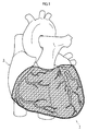
- a heart correction net 1 is a medical equipment, as shown in Fig. 1 , that is fitted to the outside of a heart 3 and inhibits the heart 3 from excessively expanding.
- This heart correction net 1 is knitted by a computerized knitting machine that is capable of knitting a knitting thread into a multidimensional shape.
- the heart correction net 1 is formed by taking images of the multidimensional shape of the heart 3 of each patient with a tomographic apparatus, such as MRI, and by using paper-pattern data created based on the tomographic images.
- the shape of the heart correction net 1 consequently coincides with the multidimensional shape of the heart 3, which snugly conforms to the heart 3 of each patient irrespective of the size and shape differences. It is to be noted that, although knitted fabric of the heart correction net 1 is illustrated so as to have tetragonal stiches in Fig. 1 , this is merely descriptive for simplification of the drawing and does not show any specific shape of the actual stitches.
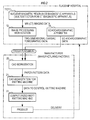
- the manufacturing system of the heart correction net 1 includes, as shown in Fig. 2 , a nuclear magnetic resonance diagnostic apparatus 11 (to be also referred to as MRI 11) (or to be alternatively referred to as a multi-detector CT 11') (to be also referred to as MDCT 11'), an image processing workstation 12 (to be also referred to as a workstation 12), an echocardiographic apparatus 14 (to be also referred to as an examination apparatus 14), a CAD workstation 20 (to be also referred to as a workstation 20), a CAD workstation for knitting 21 (to be also referred to as a workstation 21), and a computerized knitting machine for weft knitting 22 (to be also referred to as a knitting machine 22).
- MRI 11 nuclear magnetic resonance diagnostic apparatus 11
- MDCT 11' multi-detector CT 11'
- MDCT 11' multi-detector CT 11'
- an image processing workstation 12 to be also referred to as a workstation 12
- an echocardiographic apparatus 14
- the MRI 11 (or MDCT 11'), the workstation 12, and the examination apparatus 14 are installed at mini hospitals, from which orders for the heart correction net 1 are placed, whereas the workstation 20, the workstation 21, and the knitting machine 22 are installed at a manufacturer (at a manufacturing factory) of the heart correction net 1.
- the MRI 11 takes tomographic images of human bodies with nuclear magnetic resonance
- the MDCT 11' takes tomographic images of human bodies with x-rays. Either of the MRI 11 and the MDCT 11' may be employed.
- the workstation 12 performs data processing with respect to tomographic imaging data (MRI scan data or contrast enhanced CT data) taken by the MRI 11 (or the MDCT 11').
- cardiac tomographic data cardiac MRI imaging data or cardiac CT images
- end-diastole and end-systole is extracted in the workstation 12.
- 30 images/second are taken in the imaging process, and that the data in the end-diastole is specified in electrocardiographic data and only the imaging data in the end-diastole is extracted.
- the examination apparatus 14 exams the configuration of a heart based on the reflection of ultrasonic waves, and obtains more accurate configuration of the heart when used together with the MRI 11 (or the MDCT 11'). Moreover, by using the examination apparatus 14 and accurately diagnosing the clinical condition of each patient with mitral insufficiency, diagnosis can be made whether a treatment with the heart correction net 1 is applicable. Moreover, the amount of reefing of a mitral valve with the heart correction net 1 and the amount of reefing in the short diameter of a heart with the heart correction net 1 in the papillary muscle level can be determined.
- the workstation 20 performs data processing based on data sent from the workstation 12 and the examination apparatus 14.
- the workstation 20 includes data processing software, such as three-dimensional image construction software, general-purpose CAD software, and paper-pattern creating software.
- the three-dimensional image construction software in the above-described workstation 20 is utilized so as to conduct a process in which, from thresholds of two-dimensional tomographic data (DICOM data), obtained from the workstation 12, outlines of a heart is extracted for defining dividing points, for developing the data on a plane, and for providing various types of corrections, which will be explained later.
- DICOM data two-dimensional tomographic data
- correction values can be set, for example, for adjusting the amount of reefing.
- the data that is required for setting correction values includes: left ventricular end-diastolic dimension (LVDd), left ventricular end-systolic dimension (LVDs), long axis dimension of left ventricle, mitral annulus dimension (short diameter, long diameter), adhered position of papillary muscle, deviation amount in the position of mitral valve in systole (which is called tethering or tenting and indicates the vertical distance between a line connecting the anterior and posterior annulus and the leaflet junction of mitral valve), amount of mitral reflux (evaluated in long-axis image), and reflux region (evaluated in short-axis image).
- correction based on echocardiographic data is not performed.
- measurement is conducted based on the MD-CT images. That is to say that optimal data is constructed by utilizing the advantageous characteristics of the MRI 11 (or MDCT 11') and the examination apparatus 14. Issues, such as whether to conduct correction based on echocardiographic data, if such correction is adopted, the optimal degree of the correction, and so on are cooperatively considered between, for example, a cardiac surgeon and a person in charge of image processing in the manufacturer side. If necessary, such issues can be discussed with an orderer (a cardiac surgeon in the mini hospital side) so as to eventually complete data that is potentially optimal for each individual case.
- paper-pattern data is created in which a three-dimensional heart shape, corrected after extraction, is two-dimensionally developed for knitting the heart correction net 1.
- the workstation 21 controls the knitting machine 22 based on the paper-pattern data in two-dimensions (a bitmap format file) that is transmitted from the workstation 20.
- the knitting machine 22 knits a knitting thread into a knitted fabric having a multidimensional shape based on instruction from the workstation 22.
- a computerized weft knitting machine product name: SWG041, manufactured by SHIMA SEIKI MFG., LTD.
- WHOLEGARMENT registered trademark
- the knitting thread used herein is made with biocompatible materials.
- the quality and the thickness of the knitting thread is not particularly limited as long as the materials have properties (such as mechanical strength, chemical strength, and elastic properties) suitable for the intended purpose of the heart correction net 1.
- One example of such material includes a material made by twisting a single non-absorbable fiber such as polyester, polytetrafluoroethylene, foamed polytetrafluoroethylene (foamed PTFE, ePTFE), polypropylene, polydiethylene fluoride (hexafluoropropylene-vinylidene fluoride), and a material made by twisting a single absorbable fiber such as poly-glactin, polyglycolic acid, polyethylene glycol, polylactic acid, polylactide, polyglycolide, polycaprolactone, multianhydride, polyamide, polyurethane, polyester amide, polyorthoester, polydioxane, polyacetal, polyketal, polycarbonate,
- the MRI 11 (or MDCT 11'), the workstation 12, and the examination apparatus 14 are operated by a cardiac surgeon, cardiologist, or radiologist in a subsidiary hospital side so that cardiac tomographic data in two-dimension (DICOM data) and echocardiographic data are prepared in the subsidiary hospital side.
- the two-dimensional tomographic data and the echocardiographic data are transmitted through a communication line to the manufacturer (the manufacturing factory).
- the above-described data processing in the workstation 20 is performed.
- the knitting data is transmitted to the workstation 21.
- the workstation 21 and the knitting machine 22 are operated by persons in charge in the manufacturer side. By knitting the thread based on the above-described knitting data, the heart correction net 1 is manufactured so as to have the configuration represented by the knitting data. The manufactured heart correction net 1 is immediately delivered to the subsidiary hospital and used.
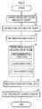
- outlines of the heart are respectively extracted with the workstation 20 (S2).
- a plurality of dividing points (16 points in the present embodiment) are defined (S3), in which a direction along the outline of a cross-section intersecting with the above-mentioned layer direction of the heart is defined as a circumferential direction.
- the dividing points are disposed on the outlines and spaced apart in the circumferential direction.
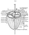
- FIG. 4 shows the outlines extracted in S2 and the dividing points defined in S3.
- a coordinate system is defined while the cross-sections of the heart are viewed from above.
- the x-axis extends in the long axial direction of the cross-section, and the positive direction of the x-axis direction is defined toward the left ventricle and the negative direction is defined toward the right ventricle.
- the y-axis extends in the short axial direction of the cross-section, and the positive direction of the y-axis is defined toward the posterior surface of the heart and the negative direction is defined toward the anterior surface of the heart.
- the positive direction of the z-axis is directed upward. According to this coordinate system, various setting and conversion of coordinates are conducted.
- the positions of layers #1 to #8 shown in Fig. 4 are image-taking positions for cross-sections.
- the eight outlines extracted in S2 are extracted from the cross-sectional images taken at these image-taking positions.
- the respective positions (of layers #1 to #8) in the layer direction are aligned from the layer #0, which is the point of origin disposed on the tip of the apex of the heart, in the order of layer #1 to #8 toward the base of the heart.
- the dividing points are defined in S3 so that 16 points are defined on each of the outlines.
- the dividing points are defined on each of the outlines in a counterclockwise around the z-axis along the outlines in the order of the dividing points #0 to #15.
- the dividing points #0 and #8 are disposed on the intersecting points of the cross-section and the x-axis (that is, on the both end positions in the long diameter of the cross-section of the heart), which are shown in the figure.
- the dividing points #4 and #12 are defined on a boundary between the left ventricle and the right ventricle. In Fig.
- the y-axis is shown so as to extend via the dividing points #4 and #12, it is only for convenience of illustration and the boundary between the left ventricle and the right ventricle are not necessarily located on the y-axis.
- the dividing points #4 and #12 may be disposed away from the y-axis.
- the remaining dividing points #1 to #3, #5 to #7, #9 to #11, #13 to #15 are arbitrarily disposed so as to be spaced apart as much as necessary to represent the contour of a heart.
- a larger number of the dividing points can more accurately represents the contour of a heart, which, however, increases the amount of data.
- the number of dividing points is preferably kept within a range necessary to represent the feature of the contour of the heart without increase the number to an excessive extent.
- three dividing points are respectively disposed between the above-described dividing points #0, #4, #8, #12 in the present embodiment. As a result, 16 dividing points are disposed on each of the outlines.
- the three-dimensional contour of the heart is divided into a plurality of divided regions, each of which is surrounded by dividing lines connecting the dividing points along the surface of the heart, and the divided regions are developed on a two-dimensional plane (S4).
- a line segment connecting the plurality of the dividing points adjacently disposed along the circumferential direction is referred to as a line segment in the circumferential direction.
- the line segment in the circumferential direction is disposed on a position so as to substantially coincide with the above-described outline.
- a line segment connecting the plurality of the dividing points having a proximate positional relation between the plurality of the outlines adjacently disposed, and a line segment connecting the tip of the apex of the heart and the dividing point disposed on the outline located proximate to the apex are each referred to as a line segment in the layer direction.
- the divided regions become either one of quadrangular regions, each having vertexes, consisting of four dividing points, and four sides, consisting of two line segments in the circumferential direction and two line segments in the layer direction, or triangular regions, each having vertexes, consisting of two dividing points and the tip, and three sides, consisting of one line segment in the circumferential direction, and two line segments in the layer direction.
- quadrangular divided regions are respectively developed into divided regions in isosceles trapezoidal shapes on the two-dimensional plane.
- a quadrangular divided region PQRS defined by the dividing points P, Q, R, and S, has four sides L1, L2, L3, and L4. These four points in three-dimensional space do not often exist in a same plane.
- a triangle PQR and a triangle PRS exist on separate planes that intersect with the line segment PR.
- coordinate transformation is performed so as to approximate the shape of the divided region PQRS with an isosceles trapezoid and to develop the approximated shape on a two-dimensional plane. Specifically, when the above-described divided region PQRS is transformed into an isosceles trapezoid, as shown in Fig.
- the line segments in the circumferential direction PQ and SR are changed so as to be parallel to the lateral axis of the two-dimensional plane, the lengths L1 and L3 of the respective line segments in the circumferential direction PQ and RS remain to be the identical lengths L1 and L3 of the line segments in the circumferential direction PQ and RS prior to the development, and the height of the isosceles trapezoid is changed to the average length of the line segments in the layer direction L2 and L4 prior to the development, i.e., (L2+L4)/2.
- the divided regions in triangular shapes are developed into divided regions in isosceles triangular shapes on a two-dimensional plane.
- Fig. 5C shows an example of divided regions transformed into an isosceles trapezoid or an isosceles triangle by the above-described technique.
- such divided regions are aligned in the layer direction making 16 rows.
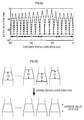
- Fig. 6A shows all the 16 rows of the divided regions.
- the ranges shown with A, B, C, and D in Fig. 6A respectively correspond to the ranges A, B, C, and D in Fig. 4 .
- the range A corresponds to the contour of the rear surface of the left ventricle developed on a two-dimensional plane.
- the range B corresponds to the posterior surface of the right ventricle
- the range C corresponds to the anterior surface of the right ventricle
- the range D corresponds to the anterior surface of the left ventricle respectively.
- the 16 rows of the divided regions shown in Fig. 6A are divided regions developed on a two-dimensional plane, in which a separation created between each of the divided regions along the line segment in the layer direction is tolerated and an approximate shape of each divided region is maintained.
- a first correction in the circumferential direction is performed in which, while the entire length in the circumferential direction is maintained, coordinates are transformed by enlarging/reducing respective ranges so that the lengths of the ranges C+D, corresponding to the anterior surface of the heart, and the ranges A+B, corresponding to the posterior surface of the heart, become isometric.
- the ranges C+D corresponding to the anterior surface of the heart
- the ranges A+B corresponding to the posterior surface of the heart
- the ranges C+D, corresponding to the anterior surface of the heart is enlarged, whereas the ranges A+B, corresponding to the posterior surface of the heart, is reduced.
- the boundary between the range B and the range C is brought to the middle point of the entire length in the circumferential direction.
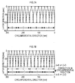
- a second correction in the circumferential direction is performed in which, while the entire length in the circumferential direction is maintained, coordinates are transformed by enlarging/reducing the respective ranges in the circumferential direction so that the range C, corresponding to the anterior surface of the right ventricle of the heart, and the range B, corresponding to the posterior surface of the right ventricle of the heart, become isometric, the range D, corresponding to the anterior surface of the left ventricle of the heart, and the range, corresponding to the posterior surface of the left ventricle A of the heart, become isometric, and the ratio of the lengths in the circumferential direction of the ranges B+C, corresponding to the right ventricle of the heart, and the ranges A+D, corresponding to the left ventricle of the heart, becomes equivalent to the ratio prior to the enlarging/reducing correction in the circumferential direction (at the point in time shown in Fig. 6A or Fig. 7A ).
- the divided regions in the 16 rows are respectively formed as shown with black lines in Fig. 8A , in which the ranges B and C become isometric, and the ranges A and D also become isometric. Moreover, with respect to the ranges B+C and the ranges A+D, the ratio of the lengths in the circumferential direction become equivalent to the ratio prior to the correction.
- the isosceles trapezoidal divided regions are processed similarly to isosceles trapezoidal divided regions having equivalent lengths of the lower and upper bases.
- the ability of the heart correction net to fit to a heart decreases if the opening portion of the final product has a narrowing shape.
- the circumferential length of the heart correction net becomes shorter than the maximum circumferential length of the heart, which makes it difficult for the heart correction net to pass through the maximum circumferential portion of the heart.
- the opening portion of the heart correction net is enlarged and the ability to fit to a heart is improved. It is to be noted that such enlargement is made only in one portion in the side of the base, and that, in the range from the maximum circumferential portion of a heart to the apex of the heart, the heart correction net can be easily fitted to the outer surface of a heart without any problems.
- paper-pattern data is subsequently created (S5).
- S5 based on the development data shown with black lines in Fig. 8A , conversion is conducted for an input to the knitting machine 22, in which coordinates are transformed in a manner shown with double lines in Fig. 8A . Specifically, the double lines fill up a gap between each row by gathering the coordinates shown with black lines to the dividing points #0 and #8 in the circumferential direction.
- numeric conversion is performed both in the circumferential direction and the layer direction so that the number of knitting stitches becomes a unit of measurement.
- the length in millimeter of one stitch varies depending on the type of a knitting thread and gauges (the interval between knitting needles) of a knitting machine.
- a sample of an actual net is made so as to obtain the scales in the circumferential direction and the layer direction.
- the relation between the number of stitches and the length is specified, for example, 1.9 mm/stitch in the circumferential direction and 0.9 mm/stitch in the layer direction.
- Fig. 8B One example of the paper-pattern data created as above is shown in Fig. 8B .
- the original image is a bitmap image in which one dot corresponds to one knitting stitch.
- the linear portion, extending in the layer direction between the posterior surface of the left ventricle and the posterior surface of the right ventricle, and the linear portion, extending in the layer direction between the anterior surface of the left ventricle and the anterior surface of the right ventricle, are both added for convenience in order to knit the boundary between the range A and range B and the boundary between the range C and the range D.
- the paper-pattern data is created as described above, the paper-pattern data is provided (inputted) to the knitting machine 22 so as to knit a heart correction net (S6). As a result, a heart correction net, having the shape according to the paper-pattern data, is knitted.
- the heart correction net knitted here does not completely conform to the contour of the heart in a strict sense, since the shapes of individual dividing regions are slightly corrected.
- the shape of the heart correction net is particularly similar to the shape of a patient's heart. Therefore, the effect is expected to be the same as the effect of the technique disclosed in the above-described Patent Document 2.
- the slight correction with respect to the shapes of the individual dividing regions can make the shape of the paper-pattern data, created in S5, remarkably simplified, which can also reduce the amount of data processing necessary for manufacturing a heart correction net. Therefore, the practical advantage becomes extremely large.
- the present invention is not limited to one particular embodiment described above.
- the present invention may be carried out in various ways.
- outlines of eight layers are extracted and 16 dividing points are defined on each of the outlines.
- the number of outlines to be extracted, and the number of dividing points to be defined, for example, may be arbitrary determined respectively.
- correction in the circumferential direction and correction in the layer direction are performed in order to improve the productivity. If, for example, no problem is caused by the manufacturing process being complicated, paper-pattern data may be created from the development view shown in Fig. 6A , or from the development view shown in Fig. 7A in which only the correction in the layer direction is performed.
- paper-pattern data obtained after correction which is shown in Fig. 8A , may be directly created from the lengths of the line segments in the circumferential direction and the lengths of the line segments in the layer direction respectively.
Claims (3)
- Un procédé de fabrication d'un filet (1) de correction cardiaque qui est apte à être monté sur un côté extérieur d'un coeur et qui empêche une dilatation excessive du coeur, le procédé comprenant :une première étape, dans laquelle une direction selon laquelle un sommet et une base du coeur sont reliés, est définie comme étant une direction de couche, une image en coupe transversale d'une coupe transversale se trouvant en intersection avec la direction de couche de coeur étant prise avec un dispositif tomographique en une pluralité de points espacés dans la direction de couche ;une deuxième étape dans laquelle un contour du coeur est extrait à partir de chacune des images en coupe transversale faisant partie d'une pluralité d'images prises dans la première étape ;une troisième étape dans laquelle une direction s'étendant le long d'un contour de la coupe transversale venant en intersection avec la direction de couche du coeur est définie comme étant une direction circonférentielle, par rapport à une forme tridimensionnelle reconstruite sur la base d'une pluralité des contours extraits dans la deuxième étape, un point de division étant défini au niveau d'une pluralité de points espacés dans la direction circonférentielle ;une quatrième étape dans laquelle, sur la base d'une pluralité des points de division définis dans la troisième étape, un contour du coeur en trois dimensions est divisé en des zones divisées, chacune des zones divisées étant entourée par des lignes de séparation reliant la pluralité de points de division, tandis qu'une forme approximative de chacune des zones divisées est maintenue, chacune des zones divisées étant développée sur un plan à deux dimensions, une division partielle entre chacune des zones divisées étant tolérée, et des données de développement étant créées, lesquelles comprennent des informations de positionnement après développement en rapport à la pluralité de points de division sur le plan en deux dimensions ;une cinquième étape, dans laquelle, sur la base des données de développement créées dans la quatrième étape, des données de motif-papier sont créées, qui sont nécessaires lorsque le filet de correction de coeur est tricoté avec une machine à tricoter informatisée ; etune sixième étape dans laquelle, sur la base des données de motif-papier créées dans la cinquième étape, le filet de correction de coeur est tricoté avec la machine à tricoter informatisée (22),dans la quatrième étape, un "segment de ligne reliant la pluralité des points de division disposés de façon adjacente le long de la direction circonférentielle" est défini comme étant un segment de droite s'étendant dans la direction circonférentielle, "un segment de ligne reliant la pluralité de points de division ayant une relation de positionnement de proximité entre la pluralité de contours disposés de façon adjacente", "un segment de ligne reliant une extrémité de la pointe du coeur et le point de division disposé sur le contour qui est situé à proximité du sommet" sont chacun définis comme étant un segment de ligne s'étendant dans la direction de couche, et "des zones quadrangulaires ayant chacune des sommets, composées de quatre points de division faisant partie de la pluralité de ces points, et quatre côtés, consistant en deux segments de ligne faisant partie d'une pluralité de segments de ligne s'étendant dans la direction circonférentielle et en deux segments de ligne faisant partie d'une pluralité de segments de ligne s'étendant dans la direction de couche" et "des zones triangulaires ayant chacune des sommets, constituées par deux points de division de la pluralité de points de division et par la pointe, et trois côtés, constitués du segment de ligne s'étendant dans la direction circonférentielle et de deux segments de ligne faisant partie de la pluralité de segments de ligne s'étendant dans la direction de couche" sont définies comme étant les zones divisées,lorsque les zones divisées sont développées sur un plan en deux dimensions, les zones quadrangulaires divisées sont chacune développées en une forme trapézoïdale isocèle, tandis que les zones triangulaires divisées sont chacune développées en une forme triangulaire isocèle, etdans les zones divisées ayant chacune la forme trapézoïdale isocèle, la pluralité de segments de ligne s'étendant dans la direction circonférentielle est modifiée de façon à être parallèle à un axe latéral du plan à deux dimensions, des longueurs de la pluralité de segments de ligne s'étendant dans la direction circonférentielle restant identiques à des longueurs de la pluralité de segments de ligne s'étendant dans la direction circonférentielle avant le développement, et une hauteur de la forme trapézoïdale isocèle est changée en une longueur moyenne de la pluralité de segments de ligne s'étendant dans la direction de couche avant le développement, tandis que, dans les zones divisées ayant chacune la forme triangulaire isocèle, le segment de ligne s'étendant dans la direction circonférentielle est modifié de manière à être parallèle à l'axe latéral du plan à deux dimensions, une longueur du segment de ligne s'étendant dans la direction circonférentielle restant identique à la longueur du segment de ligne s'étendant dans la direction circonférentielle avant le développement, et une hauteur de la forme triangulaire isocèle étant modifiée en la longueur moyenne de la pluralité de segments de ligne s'étendant dans la direction de couche avant le développement.
- Le procédé de fabrication du filet de correction cardiaque selon la revendication 1,dans lequel, dans la quatrième étape, tandis qu'une longueur entière dans la direction circonférentielle est maintenue, une correction supplémentaire est réalisée dans la direction circonférentielle de telle sorte qu'une distance, qui correspond à une surface antérieure du coeur, et une distance correspondant à une surface postérieure de le coeur, deviennent isométriques en agrandissant / réduisant les distances respectives dans la direction circonférentielle.
- Le procédé de fabrication du filet de correction cardiaque selon la revendication 2,dans lequel, dans la quatrième étape, tandis que la totalité de la longueur dans la direction circonférentielle est maintenue, une correction supplémentaire est réalisée de telle sorte qu'une distance correspondant à une surface antérieure d'un ventricule droit du coeur, et une distance correspondant à une surface postérieure du ventricule droit du coeur, deviennent isométriques, une distance, correspondant à la surface antérieure d'un ventricule gauche du coeur, et une distance, correspondant à la surface postérieure du ventricule gauche du coeur, deviennent isométriques, et un rapport des longueurs dans la direction circonférentielle d'une distance correspondant au ventricule droit du coeur, et une distance correspondant au ventricule gauche du coeur, devient égal au rapport existant avant la correction, la correction étant effectuée en agrandissant / réduisant chacune des distances dans la direction circonférentielle.
Applications Claiming Priority (2)
| Application Number | Priority Date | Filing Date | Title |
|---|---|---|---|
| JP2012053366A JP6001280B2 (ja) | 2012-03-09 | 2012-03-09 | 心臓矯正ネットの製造方法 |
| PCT/JP2013/056513 WO2013133426A1 (fr) | 2012-03-09 | 2013-03-08 | Procédé de fabrication d'un filet de correction cardiaque |
Publications (3)
| Publication Number | Publication Date |
|---|---|
| EP2829235A1 EP2829235A1 (fr) | 2015-01-28 |
| EP2829235A4 EP2829235A4 (fr) | 2015-12-02 |
| EP2829235B1 true EP2829235B1 (fr) | 2016-08-17 |
Family
ID=49116893
Family Applications (1)
| Application Number | Title | Priority Date | Filing Date |
|---|---|---|---|
| EP13758185.6A Active EP2829235B1 (fr) | 2012-03-09 | 2013-03-08 | Procédé de fabrication d'un filet de correction cardiaque |
Country Status (5)
| Country | Link |
|---|---|
| US (1) | US9702067B2 (fr) |
| EP (1) | EP2829235B1 (fr) |
| JP (1) | JP6001280B2 (fr) |
| CN (1) | CN104220008B (fr) |
| WO (1) | WO2013133426A1 (fr) |
Cited By (13)
| Publication number | Priority date | Publication date | Assignee | Title |
|---|---|---|---|---|
| US10856984B2 (en) | 2017-08-25 | 2020-12-08 | Neovasc Tiara Inc. | Sequentially deployed transcatheter mitral valve prosthesis |
| US10940001B2 (en) | 2012-05-30 | 2021-03-09 | Neovasc Tiara Inc. | Methods and apparatus for loading a prosthesis onto a delivery system |
| US11311376B2 (en) | 2019-06-20 | 2022-04-26 | Neovase Tiara Inc. | Low profile prosthetic mitral valve |
| US11357622B2 (en) | 2016-01-29 | 2022-06-14 | Neovase Tiara Inc. | Prosthetic valve for avoiding obstruction of outflow |
| US11389291B2 (en) | 2013-04-04 | 2022-07-19 | Neovase Tiara Inc. | Methods and apparatus for delivering a prosthetic valve to a beating heart |
| US11413139B2 (en) | 2011-11-23 | 2022-08-16 | Neovasc Tiara Inc. | Sequentially deployed transcatheter mitral valve prosthesis |
| US11419720B2 (en) | 2010-05-05 | 2022-08-23 | Neovasc Tiara Inc. | Transcatheter mitral valve prosthesis |
| US11464631B2 (en) | 2016-11-21 | 2022-10-11 | Neovasc Tiara Inc. | Methods and systems for rapid retraction of a transcatheter heart valve delivery system |
| US11491006B2 (en) | 2019-04-10 | 2022-11-08 | Neovasc Tiara Inc. | Prosthetic valve with natural blood flow |
| US11497602B2 (en) | 2012-02-14 | 2022-11-15 | Neovasc Tiara Inc. | Methods and apparatus for engaging a valve prosthesis with tissue |
| US11602429B2 (en) | 2019-04-01 | 2023-03-14 | Neovasc Tiara Inc. | Controllably deployable prosthetic valve |
| US11737872B2 (en) | 2018-11-08 | 2023-08-29 | Neovasc Tiara Inc. | Ventricular deployment of a transcatheter mitral valve prosthesis |
| US11779742B2 (en) | 2019-05-20 | 2023-10-10 | Neovasc Tiara Inc. | Introducer with hemostasis mechanism |
Families Citing this family (7)
| Publication number | Priority date | Publication date | Assignee | Title |
|---|---|---|---|---|
| JP6001280B2 (ja) | 2012-03-09 | 2016-10-05 | 学校法人金沢医科大学 | 心臓矯正ネットの製造方法 |
| CN105616036B (zh) * | 2015-12-23 | 2017-05-10 | 南京航空航天大学 | 基于医学断层图像直接3d打印实体的方法 |
| CA3055394C (fr) * | 2017-03-07 | 2024-01-02 | Cd Med S.R.L. | Procede de generation d'un anneau de reparation mitrale, et anneau de reparation mitrale |
| KR102128033B1 (ko) * | 2018-05-03 | 2020-06-29 | 울산대학교 산학협력단 | 이첨판막의 판막륜 크기 결정 방법 |
| WO2020044523A1 (fr) * | 2018-08-30 | 2020-03-05 | オリンパス株式会社 | Dispositif d'enregistrement, dispositif d'observation d'images, système d'observation, procédé de commande de système d'observation, et programme de fonctionnement de système d'observation |
| WO2020096815A1 (fr) * | 2018-11-06 | 2020-05-14 | Capsulacare Llc | Dispositif de capsule pour envelopper un organe corporel ou une masse corporelle et son utilisation |
| CN113256486A (zh) * | 2021-05-25 | 2021-08-13 | 深圳市博克时代科技开发有限公司 | 三维箱包二维化方法、装置、计算机设备及存储介质 |
Family Cites Families (13)
| Publication number | Priority date | Publication date | Assignee | Title |
|---|---|---|---|---|
| AU2001238383A1 (en) * | 2000-03-10 | 2001-09-24 | Paracor Surgical, Inc. | Expandable cardiac harness for treating congestive heart failure |
| US6425856B1 (en) | 2000-05-10 | 2002-07-30 | Acorn Cardiovascular, Inc. | Cardiac disease treatment and device |
| US7174896B1 (en) * | 2002-01-07 | 2007-02-13 | Paracor Medical, Inc. | Method and apparatus for supporting a heart |
| US20040176658A1 (en) * | 2003-03-03 | 2004-09-09 | Mcmurray Brian | Warp knit fabrics useful for medical articles and methods of making same |
| US7871366B2 (en) * | 2005-04-06 | 2011-01-18 | The Texas A&M University System | Device for the modulation of cardiac end diastolic volume |
| US20060241445A1 (en) * | 2005-04-26 | 2006-10-26 | Altmann Andres C | Three-dimensional cardial imaging using ultrasound contour reconstruction |
| US20090267941A1 (en) * | 2005-04-29 | 2009-10-29 | Koninklijke Philips Electronics N. V. | Multi-surface modelling |
| US20080172073A1 (en) * | 2006-06-16 | 2008-07-17 | Searete Llc, A Limited Liability Corporation Of The State Of Delaware | Active blood vessel sleeve |
| JP4582549B2 (ja) | 2006-12-27 | 2010-11-17 | 株式会社東海メディカルプロダクツ | 心臓形態矯正ネット、およびその製造方法 |
| JP5558931B2 (ja) * | 2010-06-16 | 2014-07-23 | 日立アロカメディカル株式会社 | 超音波診断装置 |
| CN102397070B (zh) * | 2011-01-26 | 2013-06-19 | 嘉兴医孚软件有限公司 | 一种全自动分割量化心脏磁共振图像左心室的方法 |
| JP6001280B2 (ja) | 2012-03-09 | 2016-10-05 | 学校法人金沢医科大学 | 心臓矯正ネットの製造方法 |
| EP2906143A4 (fr) * | 2012-10-12 | 2016-07-13 | Mardil Inc | Système et procédé de traitement cardiaque |
-
2012
- 2012-03-09 JP JP2012053366A patent/JP6001280B2/ja active Active
-
2013
- 2013-03-08 US US14/383,919 patent/US9702067B2/en active Active
- 2013-03-08 WO PCT/JP2013/056513 patent/WO2013133426A1/fr active Application Filing
- 2013-03-08 CN CN201380013207.6A patent/CN104220008B/zh active Active
- 2013-03-08 EP EP13758185.6A patent/EP2829235B1/fr active Active
Cited By (17)
| Publication number | Priority date | Publication date | Assignee | Title |
|---|---|---|---|---|
| US11419720B2 (en) | 2010-05-05 | 2022-08-23 | Neovasc Tiara Inc. | Transcatheter mitral valve prosthesis |
| US11413139B2 (en) | 2011-11-23 | 2022-08-16 | Neovasc Tiara Inc. | Sequentially deployed transcatheter mitral valve prosthesis |
| US11497602B2 (en) | 2012-02-14 | 2022-11-15 | Neovasc Tiara Inc. | Methods and apparatus for engaging a valve prosthesis with tissue |
| US10940001B2 (en) | 2012-05-30 | 2021-03-09 | Neovasc Tiara Inc. | Methods and apparatus for loading a prosthesis onto a delivery system |
| US11617650B2 (en) | 2012-05-30 | 2023-04-04 | Neovasc Tiara Inc. | Methods and apparatus for loading a prosthesis onto a delivery system |
| US11389294B2 (en) | 2012-05-30 | 2022-07-19 | Neovasc Tiara Inc. | Methods and apparatus for loading a prosthesis onto a delivery system |
| US11389291B2 (en) | 2013-04-04 | 2022-07-19 | Neovase Tiara Inc. | Methods and apparatus for delivering a prosthetic valve to a beating heart |
| US11357622B2 (en) | 2016-01-29 | 2022-06-14 | Neovase Tiara Inc. | Prosthetic valve for avoiding obstruction of outflow |
| US11464631B2 (en) | 2016-11-21 | 2022-10-11 | Neovasc Tiara Inc. | Methods and systems for rapid retraction of a transcatheter heart valve delivery system |
| US10856984B2 (en) | 2017-08-25 | 2020-12-08 | Neovasc Tiara Inc. | Sequentially deployed transcatheter mitral valve prosthesis |
| US11793640B2 (en) | 2017-08-25 | 2023-10-24 | Neovasc Tiara Inc. | Sequentially deployed transcatheter mitral valve prosthesis |
| US11737872B2 (en) | 2018-11-08 | 2023-08-29 | Neovasc Tiara Inc. | Ventricular deployment of a transcatheter mitral valve prosthesis |
| US11602429B2 (en) | 2019-04-01 | 2023-03-14 | Neovasc Tiara Inc. | Controllably deployable prosthetic valve |
| US11491006B2 (en) | 2019-04-10 | 2022-11-08 | Neovasc Tiara Inc. | Prosthetic valve with natural blood flow |
| US11779742B2 (en) | 2019-05-20 | 2023-10-10 | Neovasc Tiara Inc. | Introducer with hemostasis mechanism |
| US11311376B2 (en) | 2019-06-20 | 2022-04-26 | Neovase Tiara Inc. | Low profile prosthetic mitral valve |
| US11931254B2 (en) | 2019-06-20 | 2024-03-19 | Neovasc Tiara Inc. | Low profile prosthetic mitral valve |
Also Published As
| Publication number | Publication date |
|---|---|
| US20150020547A1 (en) | 2015-01-22 |
| EP2829235A1 (fr) | 2015-01-28 |
| EP2829235A4 (fr) | 2015-12-02 |
| JP2013183995A (ja) | 2013-09-19 |
| WO2013133426A1 (fr) | 2013-09-12 |
| CN104220008A (zh) | 2014-12-17 |
| JP6001280B2 (ja) | 2016-10-05 |
| CN104220008B (zh) | 2016-12-21 |
| US9702067B2 (en) | 2017-07-11 |
Similar Documents
| Publication | Publication Date | Title |
|---|---|---|
| EP2829235B1 (fr) | Procédé de fabrication d'un filet de correction cardiaque | |
| US10016277B2 (en) | Heart correction net | |
| US9808213B2 (en) | Image processing apparatus, image processing method, medical image diagnostic system, and storage medium | |
| JP5738279B2 (ja) | 医用画像診断装置及び、医用画像の計測値再入力方法 | |
| CN104219997B (zh) | 医用图像诊断装置以及图像显示装置 | |
| US20130257910A1 (en) | Apparatus and method for lesion diagnosis | |
| WO2014081021A1 (fr) | Dispositif de traitement d'image, appareil d'imagerie par résonance magnétique, et procédé de traitement d'image | |
| JP2005160503A (ja) | 医用画像表示装置 | |
| US8340375B2 (en) | Medical diagnostic imaging apparatus, medical image processing method, and computer program product | |
| JP4582549B2 (ja) | 心臓形態矯正ネット、およびその製造方法 | |
| WO2013133427A1 (fr) | Procédé de fabrication d'un filet de correction cardiaque | |
| JP5100041B2 (ja) | 画像処理装置及び画像処理プログラム | |
| EP2480133B1 (fr) | Appareil et procédé pour l'acquisition d'informations de diagnostic | |
| JP6433190B2 (ja) | 画像処理装置、画像処理方法、およびプログラム | |
| JP6583722B2 (ja) | 心臓サポーターの設計方法、心臓サポーターの製造方法 | |
| JP2017202307A (ja) | 医用画像診断装置及び医用情報管理装置 | |
| TWI788065B (zh) | 骨頭切割修補輔助系統、方法及電腦程式產品 | |
| US8744150B2 (en) | Method for determining a layer orientation for a 2D layer image | |
| JP6433189B2 (ja) | 画像処理装置、画像処理方法、およびプログラム | |
| KR20220087874A (ko) | 의료영상 정합 방법 및 그 장치 | |
| JP5879098B2 (ja) | 体内臓器の動画像生成装置および体内臓器の動画像生成方法 | |
| CN115517762A (zh) | 手术路径处理方法、系统、可读存储介质和手术系统 | |
| Nieuwenhuis | Image guided left ventricular lead-implantation for cardiac resynchronization therapy: assessment of the left phrenic nerve and coronary sinus. | |
| JP2001170072A (ja) | 定位脳手術支援システム |
Legal Events
| Date | Code | Title | Description |
|---|---|---|---|
| PUAI | Public reference made under article 153(3) epc to a published international application that has entered the european phase |
Free format text: ORIGINAL CODE: 0009012 |
|
| 17P | Request for examination filed |
Effective date: 20141008 |
|
| AK | Designated contracting states |
Kind code of ref document: A1 Designated state(s): AL AT BE BG CH CY CZ DE DK EE ES FI FR GB GR HR HU IE IS IT LI LT LU LV MC MK MT NL NO PL PT RO RS SE SI SK SM TR |
|
| AX | Request for extension of the european patent |
Extension state: BA ME |
|
| DAX | Request for extension of the european patent (deleted) | ||
| RA4 | Supplementary search report drawn up and despatched (corrected) |
Effective date: 20151102 |
|
| RIC1 | Information provided on ipc code assigned before grant |
Ipc: A61B 17/00 20060101AFI20151027BHEP Ipc: A61F 2/02 20060101ALI20151027BHEP |
|
| RAP1 | Party data changed (applicant data changed or rights of an application transferred) |
Owner name: KANAZAWA INSTITUTE OF TECHNOLOGY Owner name: KANAZAWA MEDICAL UNIVERSITY Owner name: TOKAI MEDICAL PRODUCTS, INC. |
|
| RIN1 | Information on inventor provided before grant (corrected) |
Inventor name: SUZUKI, TORU Inventor name: SETO, MASAHIRO Inventor name: YAMABE, MASASHI Inventor name: AKITA, TOSHIAKI Inventor name: TAKESUE, NAOYUKI |
|
| GRAP | Despatch of communication of intention to grant a patent |
Free format text: ORIGINAL CODE: EPIDOSNIGR1 |
|
| INTG | Intention to grant announced |
Effective date: 20160329 |
|
| RAP1 | Party data changed (applicant data changed or rights of an application transferred) |
Owner name: KANAZAWA INSTITUTE OF TECHNOLOGY Owner name: TOKAI MEDICAL PRODUCTS, INC. Owner name: KANAZAWA MEDICAL UNIVERSITY |
|
| GRAS | Grant fee paid |
Free format text: ORIGINAL CODE: EPIDOSNIGR3 |
|
| GRAA | (expected) grant |
Free format text: ORIGINAL CODE: 0009210 |
|
| AK | Designated contracting states |
Kind code of ref document: B1 Designated state(s): AL AT BE BG CH CY CZ DE DK EE ES FI FR GB GR HR HU IE IS IT LI LT LU LV MC MK MT NL NO PL PT RO RS SE SI SK SM TR |
|
| REG | Reference to a national code |
Ref country code: GB Ref legal event code: FG4D |
|
| REG | Reference to a national code |
Ref country code: CH Ref legal event code: EP |
|
| REG | Reference to a national code |
Ref country code: IE Ref legal event code: FG4D |
|
| REG | Reference to a national code |
Ref country code: AT Ref legal event code: REF Ref document number: 820271 Country of ref document: AT Kind code of ref document: T Effective date: 20160915 |
|
| REG | Reference to a national code |
Ref country code: DE Ref legal event code: R096 Ref document number: 602013010433 Country of ref document: DE |
|
| REG | Reference to a national code |
Ref country code: NL Ref legal event code: MP Effective date: 20160817 |
|
| REG | Reference to a national code |
Ref country code: LT Ref legal event code: MG4D |
|
| REG | Reference to a national code |
Ref country code: AT Ref legal event code: MK05 Ref document number: 820271 Country of ref document: AT Kind code of ref document: T Effective date: 20160817 |
|
| PG25 | Lapsed in a contracting state [announced via postgrant information from national office to epo] |
Ref country code: FI Free format text: LAPSE BECAUSE OF FAILURE TO SUBMIT A TRANSLATION OF THE DESCRIPTION OR TO PAY THE FEE WITHIN THE PRESCRIBED TIME-LIMIT Effective date: 20160817 Ref country code: RS Free format text: LAPSE BECAUSE OF FAILURE TO SUBMIT A TRANSLATION OF THE DESCRIPTION OR TO PAY THE FEE WITHIN THE PRESCRIBED TIME-LIMIT Effective date: 20160817 Ref country code: HR Free format text: LAPSE BECAUSE OF FAILURE TO SUBMIT A TRANSLATION OF THE DESCRIPTION OR TO PAY THE FEE WITHIN THE PRESCRIBED TIME-LIMIT Effective date: 20160817 Ref country code: NL Free format text: LAPSE BECAUSE OF FAILURE TO SUBMIT A TRANSLATION OF THE DESCRIPTION OR TO PAY THE FEE WITHIN THE PRESCRIBED TIME-LIMIT Effective date: 20160817 Ref country code: NO Free format text: LAPSE BECAUSE OF FAILURE TO SUBMIT A TRANSLATION OF THE DESCRIPTION OR TO PAY THE FEE WITHIN THE PRESCRIBED TIME-LIMIT Effective date: 20161117 Ref country code: LT Free format text: LAPSE BECAUSE OF FAILURE TO SUBMIT A TRANSLATION OF THE DESCRIPTION OR TO PAY THE FEE WITHIN THE PRESCRIBED TIME-LIMIT Effective date: 20160817 |
|
| PG25 | Lapsed in a contracting state [announced via postgrant information from national office to epo] |
Ref country code: PL Free format text: LAPSE BECAUSE OF FAILURE TO SUBMIT A TRANSLATION OF THE DESCRIPTION OR TO PAY THE FEE WITHIN THE PRESCRIBED TIME-LIMIT Effective date: 20160817 Ref country code: SE Free format text: LAPSE BECAUSE OF FAILURE TO SUBMIT A TRANSLATION OF THE DESCRIPTION OR TO PAY THE FEE WITHIN THE PRESCRIBED TIME-LIMIT Effective date: 20160817 Ref country code: AT Free format text: LAPSE BECAUSE OF FAILURE TO SUBMIT A TRANSLATION OF THE DESCRIPTION OR TO PAY THE FEE WITHIN THE PRESCRIBED TIME-LIMIT Effective date: 20160817 Ref country code: ES Free format text: LAPSE BECAUSE OF FAILURE TO SUBMIT A TRANSLATION OF THE DESCRIPTION OR TO PAY THE FEE WITHIN THE PRESCRIBED TIME-LIMIT Effective date: 20160817 Ref country code: LV Free format text: LAPSE BECAUSE OF FAILURE TO SUBMIT A TRANSLATION OF THE DESCRIPTION OR TO PAY THE FEE WITHIN THE PRESCRIBED TIME-LIMIT Effective date: 20160817 Ref country code: PT Free format text: LAPSE BECAUSE OF FAILURE TO SUBMIT A TRANSLATION OF THE DESCRIPTION OR TO PAY THE FEE WITHIN THE PRESCRIBED TIME-LIMIT Effective date: 20161219 Ref country code: GR Free format text: LAPSE BECAUSE OF FAILURE TO SUBMIT A TRANSLATION OF THE DESCRIPTION OR TO PAY THE FEE WITHIN THE PRESCRIBED TIME-LIMIT Effective date: 20161118 |
|
| REG | Reference to a national code |
Ref country code: FR Ref legal event code: PLFP Year of fee payment: 5 |
|
| PG25 | Lapsed in a contracting state [announced via postgrant information from national office to epo] |
Ref country code: RO Free format text: LAPSE BECAUSE OF FAILURE TO SUBMIT A TRANSLATION OF THE DESCRIPTION OR TO PAY THE FEE WITHIN THE PRESCRIBED TIME-LIMIT Effective date: 20160817 Ref country code: EE Free format text: LAPSE BECAUSE OF FAILURE TO SUBMIT A TRANSLATION OF THE DESCRIPTION OR TO PAY THE FEE WITHIN THE PRESCRIBED TIME-LIMIT Effective date: 20160817 |
|
| REG | Reference to a national code |
Ref country code: DE Ref legal event code: R097 Ref document number: 602013010433 Country of ref document: DE |
|
| PG25 | Lapsed in a contracting state [announced via postgrant information from national office to epo] |
Ref country code: SM Free format text: LAPSE BECAUSE OF FAILURE TO SUBMIT A TRANSLATION OF THE DESCRIPTION OR TO PAY THE FEE WITHIN THE PRESCRIBED TIME-LIMIT Effective date: 20160817 Ref country code: DK Free format text: LAPSE BECAUSE OF FAILURE TO SUBMIT A TRANSLATION OF THE DESCRIPTION OR TO PAY THE FEE WITHIN THE PRESCRIBED TIME-LIMIT Effective date: 20160817 Ref country code: SK Free format text: LAPSE BECAUSE OF FAILURE TO SUBMIT A TRANSLATION OF THE DESCRIPTION OR TO PAY THE FEE WITHIN THE PRESCRIBED TIME-LIMIT Effective date: 20160817 Ref country code: CZ Free format text: LAPSE BECAUSE OF FAILURE TO SUBMIT A TRANSLATION OF THE DESCRIPTION OR TO PAY THE FEE WITHIN THE PRESCRIBED TIME-LIMIT Effective date: 20160817 Ref country code: BG Free format text: LAPSE BECAUSE OF FAILURE TO SUBMIT A TRANSLATION OF THE DESCRIPTION OR TO PAY THE FEE WITHIN THE PRESCRIBED TIME-LIMIT Effective date: 20161117 Ref country code: BE Free format text: LAPSE BECAUSE OF FAILURE TO SUBMIT A TRANSLATION OF THE DESCRIPTION OR TO PAY THE FEE WITHIN THE PRESCRIBED TIME-LIMIT Effective date: 20160817 |
|
| PLBE | No opposition filed within time limit |
Free format text: ORIGINAL CODE: 0009261 |
|
| STAA | Information on the status of an ep patent application or granted ep patent |
Free format text: STATUS: NO OPPOSITION FILED WITHIN TIME LIMIT |
|
| 26N | No opposition filed |
Effective date: 20170518 |
|
| PG25 | Lapsed in a contracting state [announced via postgrant information from national office to epo] |
Ref country code: SI Free format text: LAPSE BECAUSE OF FAILURE TO SUBMIT A TRANSLATION OF THE DESCRIPTION OR TO PAY THE FEE WITHIN THE PRESCRIBED TIME-LIMIT Effective date: 20160817 |
|
| REG | Reference to a national code |
Ref country code: CH Ref legal event code: PL |
|
| PG25 | Lapsed in a contracting state [announced via postgrant information from national office to epo] |
Ref country code: MC Free format text: LAPSE BECAUSE OF FAILURE TO SUBMIT A TRANSLATION OF THE DESCRIPTION OR TO PAY THE FEE WITHIN THE PRESCRIBED TIME-LIMIT Effective date: 20160817 |
|
| REG | Reference to a national code |
Ref country code: IE Ref legal event code: MM4A |
|
| PG25 | Lapsed in a contracting state [announced via postgrant information from national office to epo] |
Ref country code: LU Free format text: LAPSE BECAUSE OF NON-PAYMENT OF DUE FEES Effective date: 20170308 |
|
| PG25 | Lapsed in a contracting state [announced via postgrant information from national office to epo] |
Ref country code: IE Free format text: LAPSE BECAUSE OF NON-PAYMENT OF DUE FEES Effective date: 20170308 Ref country code: CH Free format text: LAPSE BECAUSE OF NON-PAYMENT OF DUE FEES Effective date: 20170331 Ref country code: LI Free format text: LAPSE BECAUSE OF NON-PAYMENT OF DUE FEES Effective date: 20170331 |
|
| REG | Reference to a national code |
Ref country code: FR Ref legal event code: PLFP Year of fee payment: 6 |
|
| REG | Reference to a national code |
Ref country code: GB Ref legal event code: 732E Free format text: REGISTERED BETWEEN 20180517 AND 20180523 |
|
| REG | Reference to a national code |
Ref country code: DE Ref legal event code: R082 Ref document number: 602013010433 Country of ref document: DE Representative=s name: SEEMANN & PARTNER PATENTANWAELTE MBB, DE Ref country code: DE Ref legal event code: R081 Ref document number: 602013010433 Country of ref document: DE Owner name: ICORNET LABORATORY CO., LTD., NAGOYA-SHI, JP Free format text: FORMER OWNERS: KANAZAWA INSTITUTE OF TECHNOLOGY, NONOICHI-SHI, ISHIKAWA, JP; KANAZAWA MEDICAL UNIVERSITY, ISHIKAWA, JP; TOKAI MEDICAL PRODUCTS, INC., KASUGAI-SHI, AICHI, JP |
|
| PG25 | Lapsed in a contracting state [announced via postgrant information from national office to epo] |
Ref country code: MT Free format text: LAPSE BECAUSE OF NON-PAYMENT OF DUE FEES Effective date: 20170308 |
|
| REG | Reference to a national code |
Ref country code: FR Ref legal event code: TP Owner name: ICORNET LABORATORY CO., LTD., JP Effective date: 20180824 |
|
| PG25 | Lapsed in a contracting state [announced via postgrant information from national office to epo] |
Ref country code: AL Free format text: LAPSE BECAUSE OF FAILURE TO SUBMIT A TRANSLATION OF THE DESCRIPTION OR TO PAY THE FEE WITHIN THE PRESCRIBED TIME-LIMIT Effective date: 20160817 |
|
| PG25 | Lapsed in a contracting state [announced via postgrant information from national office to epo] |
Ref country code: HU Free format text: LAPSE BECAUSE OF FAILURE TO SUBMIT A TRANSLATION OF THE DESCRIPTION OR TO PAY THE FEE WITHIN THE PRESCRIBED TIME-LIMIT; INVALID AB INITIO Effective date: 20130308 |
|
| PG25 | Lapsed in a contracting state [announced via postgrant information from national office to epo] |
Ref country code: CY Free format text: LAPSE BECAUSE OF FAILURE TO SUBMIT A TRANSLATION OF THE DESCRIPTION OR TO PAY THE FEE WITHIN THE PRESCRIBED TIME-LIMIT Effective date: 20160817 |
|
| PG25 | Lapsed in a contracting state [announced via postgrant information from national office to epo] |
Ref country code: MK Free format text: LAPSE BECAUSE OF FAILURE TO SUBMIT A TRANSLATION OF THE DESCRIPTION OR TO PAY THE FEE WITHIN THE PRESCRIBED TIME-LIMIT Effective date: 20160817 |
|
| PG25 | Lapsed in a contracting state [announced via postgrant information from national office to epo] |
Ref country code: TR Free format text: LAPSE BECAUSE OF FAILURE TO SUBMIT A TRANSLATION OF THE DESCRIPTION OR TO PAY THE FEE WITHIN THE PRESCRIBED TIME-LIMIT Effective date: 20160817 |
|
| PG25 | Lapsed in a contracting state [announced via postgrant information from national office to epo] |
Ref country code: IS Free format text: LAPSE BECAUSE OF FAILURE TO SUBMIT A TRANSLATION OF THE DESCRIPTION OR TO PAY THE FEE WITHIN THE PRESCRIBED TIME-LIMIT Effective date: 20161217 |
|
| PGFP | Annual fee paid to national office [announced via postgrant information from national office to epo] |
Ref country code: FR Payment date: 20230324 Year of fee payment: 11 |
|
| PGFP | Annual fee paid to national office [announced via postgrant information from national office to epo] |
Ref country code: GB Payment date: 20230322 Year of fee payment: 11 Ref country code: DE Payment date: 20230321 Year of fee payment: 11 |
|
| PGFP | Annual fee paid to national office [announced via postgrant information from national office to epo] |
Ref country code: IT Payment date: 20230328 Year of fee payment: 11 |
|
| PGFP | Annual fee paid to national office [announced via postgrant information from national office to epo] |
Ref country code: DE Payment date: 20240320 Year of fee payment: 12 Ref country code: GB Payment date: 20240320 Year of fee payment: 12 |