EP2829191B1 - Weicher einziehbarer Griff - Google Patents
Weicher einziehbarer Griff Download PDFInfo
- Publication number
- EP2829191B1 EP2829191B1 EP14175324.4A EP14175324A EP2829191B1 EP 2829191 B1 EP2829191 B1 EP 2829191B1 EP 14175324 A EP14175324 A EP 14175324A EP 2829191 B1 EP2829191 B1 EP 2829191B1
- Authority
- EP
- European Patent Office
- Prior art keywords
- handle
- grip
- loop
- slot
- retractable handle
- Prior art date
- Legal status (The legal status is an assumption and is not a legal conclusion. Google has not performed a legal analysis and makes no representation as to the accuracy of the status listed.)
- Active
Links
Images


Classifications
-
- A—HUMAN NECESSITIES
- A45—HAND OR TRAVELLING ARTICLES
- A45C—PURSES; LUGGAGE; HAND CARRIED BAGS
- A45C13/00—Details; Accessories
- A45C13/26—Special adaptations of handles
-
- A—HUMAN NECESSITIES
- A45—HAND OR TRAVELLING ARTICLES
- A45C—PURSES; LUGGAGE; HAND CARRIED BAGS
- A45C3/00—Flexible luggage; Handbags
- A45C3/06—Ladies' handbags
Definitions
- the present application relates to a retractable handle.
- a retractable handle for a leather goods or luggage This is for example a leather goods flexible luggage type, for example a bag, including a handbag.
- At least one handle can retract to take the least possible space, visually and / or physically.
- the handle remains strong enough to support the article and, where appropriate, its contents.
- This aspect is particularly important for leather goods, fabrics or similar materials for which a tear is, for example, often irremediable, especially in the sense that the sewing would leave a trace that not only from an aesthetic point of view would be intolerable but, in addition, from a point of view of the strength of the article would create a local weakness that could lead more easily to a new tear.
- This handle 1 comprises a handle 2 capable of sliding in loops, such as the loop 4, fixed on a support 5.
- the handle 2 can adopt a retracted position in which it marries at least in part a surface of the support 5.
- the present invention aims at solving at least in part the aforementioned drawbacks, further leading to other advantages.
- Such a handle is thus able to slide easily while remaining solid. It also makes it possible to prevent one end of the handle from being re-usable.
- a stop makes it possible to form an end of the race for the passerby, especially when the handle is in the carrying position.
- Such an abutment is also preferably formed on the side of the inner face of the support.
- the guide lug is for example fixed to the support by a seam, a rivet, a nail or glue.
- the guide tab In a case where the guide tab is rigid, it is possibly fixed by only one of its ends. In a case where the guide tab is flexible, it is preferably fixed by its two ends.
- the at least one stop is formed at least in part by the at least one slot.
- the at least one stop is formed at least in part by a protuberance of the at least one guide lug, for example in the form of a cocked hat. This makes it possible in particular to avoid pulling on the slot, which could risk tearing it, especially if the article for which the handle is intended is very heavy.
- the protuberance of the at least one guide lug is formed near the at least one slot. This closes a day that would be formed by the slot, and makes the handle more aesthetic.
- At least a portion of the at least one guide tab, cooperating with the at least one passer, is parallel to at least the inner face of the support.
- At least one of the loop, the support and the at least one guide lug is at least partially made of leather.
- an at least partially flexible bag comprising at least one retractable handle having all or some of the features described above is also proposed.
- the at least one retractable handle forms a first retractable handle positioned on a first side of an opening for accessing a content of the bag, the bag further comprising at least one second retractable handle having all or some of the previously described features positioned on a second side of the opening.
- the first retractable handle and the second retractable handle are each parallel to an edge of the opening. Such a position allows to structure the edges of the opening, especially so that they remain against each other to close the opening when the bag is worn.
- the bag further comprises two additional handles, called third handle and fourth handle. This allows to have a bag with four handles to wear it differently as needed.
- the retractable handles then form so-called internal handles and the additional handles form so-called external handles.
- internal is meant here the fact that the handle is positioned between another handle and the opening of the bag (and not the fact that the handle would be located inside the bag).
- the internal handles are thus high handles and the external handles of the low handles.
- first retractable handle is located between the third handle and the opening and the second retractable handle is located between the fourth handle and the opening.
- the handle of the first retractable handle and the handle of the second retractable handle (in the carrying position) have a length equal to or greater than a length of a handle of the third handle and a handle of the fourth handle.
- the length of the internal handles allows in particular a worn "hollow arm”.
- the handle of the first retractable handle and the handle of the second retractable handle take the retracted position in a position of the bag carried by the third handle and the fourth handle.
- the retractable handles thus contribute to the closure of the opening, for example, and do not hinder the wearing of the bag.
- the fact that the internal handles are retractable responds to an aesthetic concern: the beauty of the top of the bag when it is not held by the internal handles.
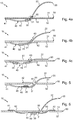
- Figures 2 to 6 have only one end of a retractable handle according to one embodiment of the invention, for example the left end.
- the other end is for example fixed or retractable thanks to any system. It can in particular be identical to the end described below.
- a retractable handle 10 according to one embodiment of the invention comprises in particular a support 50, a handle 20 and a guide lug 40.
- the support 50 has an outer face 51, an inner face 52 and a through slot 60 through which the handle 20 passes.
- the slot 60 here has a half-moon shape, to form a tongue 61 covering a part of the 20. It facilitates and guide a sliding of the handle 20 in the slot 60 and prevent a day does not appear, which improves the aesthetics.
- outside and inside are of course used here by convention, according to a normal mode of use, to facilitate the description which follows.
- the face of the support described as being the outer face is thus typically oriented on the side of the article where is the portion of the handle to be input, that is to say generally the central portion of the handle.
- the loop 20, here flexible, comprises a first portion 21 located on the side of the inner face 52 of the support 50 and a second portion 22 located on the side of the outer face 51 of the support 50.
- the second portion 22 forms, at least partially , the part of the handle to be seized.
- the first portion 21 of the loop 20 has a loop 30 which surrounds here the guide lug 40.
- the loop 30 is here located at a free end of the first portion 21 of the loop 20. This allows in particular to save the material, to offer a long run to the handle 20 and / or to avoid that a portion of the handle 20 which extends beyond the loop 30 does not rebel or interfere with the sliding of the handle 20
- the loop 30 is wider than the first portion 21 of the loop 20. It is also preferably wider than the slot 60 to prevent it from passing through.
- the handle 20 is widened towards a central zone with respect to its ends, that is to say typically in its second part 22. Such widening allows a better ergonomics. This also makes it possible to brake a passage of the handle 20 through the slot 60, or even to prevent the handle 20 from passing entirely through the slot 60, in particular when the handle is not yet connected by at least one of its ends to another element, such as a guide lug.
- the guide tab 40 is here disposed on the side of the inner face 52 of the support 50.
- the guide tab 40 is sewn on the inner face 52 of the support 50 by its first end 41 and by its second end 42. It is for example made at least partially leather which gives it a certain strength and flexibility. In another embodiment not shown, if the guide tab was made for example by a metal rod, a fixation by a single end could be sufficient.
- the guide lug 40 is here substantially parallel to the inner face 52 of the support 50. It is for example pressed against the inner face 52 of the support 50 when the support 50 is stretched or laid flat.
- the guide lug 40 has at least one portion 45 between its two ends 41 and 42.
- the width of this portion is here constant and cooperates with the passage 30 of the first portion 21 of the handle 20 to allow the passer 30 to slide freely on it.
- the portion 45 of the guide tab 40 may have an oblong shape (in its width) or curved (in its thickness), substantially widened towards its center, so as to form a brake for promote the maintenance of the handle 20 in the carrying position or in the retracted position.
- the second end 42 here has a protuberance 43 in the form of a gendarme cap which serves as a stop for a running of the passer 30 when it slides on the portion 45 of the guide tab 40.
- the second end 42 is here sewn on the inner face 52 of the support 50, close to the slot 60, so that the protrusion 43 covers at least part of the slot 60 on the side of the inner face 52. This allows in particular to hide the slot 60 on one side to prevent a day from appearing. This is reinforced by the presence of the tongue 61 of the slot 60.
- the protuberance 43 is thus located upstream of the slot 60 relative to the travel of the passer 30 on the guide lug 40, which allows to prevent the loop 30 from coming into abutment with the slot 60 and pulling it, which could damage or tear it.
- the portion 45 of the guide lug 40 extends from the protrusion 43 to the first end 41.
- the first end 41 is preferably of rounded, ogival or rectangular shape with cut sides. It can have any other form.
- the retractable handle 10 thus comprises a stop formed here by the protuberance 43. However, it could however be formed differently, for example by a periphery of the slot 60 or by any added element.
- the stop generally makes it possible to form a limit switch for the passer 30 when the handle 20 is in the carrying position. It is preferably formed on the side of the inner face 52 of the support 50.
- the guide lug 40 is positioned parallel to an edge 53 of the support 50. Such an arrangement makes it possible in particular to structure the edge 53.
- a cooperation between the passer 30 and the guide lug 40 makes it possible in particular to prevent the end of the handle 20 from becoming worn again. Indeed, it is guided (and therefore constrained) by the guide lug 40 which follows (at least by its portion 45) the inner face 52 of the support 50.
- the portion 45 of the guide lug 40 which follows the inner face 52 support 50 a preferably, a length equal to or greater than a travel of the passer defined between the carrying position and the retracted position of the handle 20.
- the figure 4a shows the carrying position. In this position, the loop 30 of the first portion 21 of the loop 20 is in contact with the stop which is formed here by the protuberance 43 of the guide lug 40.
- the stop which is formed here by the protuberance 43 of the guide lug 40.
- Such a protrusion 43 is formed at the end 42 of the guide lug 40 and thus avoids pulling on the slot 60 during the port, which could damage it, for example tear if the object to wear is very heavy.
- the loop 30 is limited in its displacement in the retracted position by the length of the loop 20 with respect to the length and position of the guide lug 40.
- the loop 30 comes, in the retracted position, against another stop, for example formed by another protuberance which would be formed near the end 41 of the guide tab 40.
- the embodiment of the figure 5 differs in that the second end 42 of the guide tab 40 is here positioned and fixed, for example sewn, on the outer face 51 of the support 50.
- the guide lug 40 passes through the slot 60.
- the stop is then here formed by a periphery of the slot 60 as well as by a fold 44 formed by the guide lug 40.
- the portion 45 of the guide lug 40 parallel to the inner face 52 of the support 50 and plated against the inner face 52 of the support 50 when the support 50 is stretched or laid flat, is formed by a portion of the guide lug 40 between the first end 41 and the fold 44.
- the portion 45 of the guide lug 40 as before has a constant width and cooperates with the loop 30 of the first portion 21 of the loop 20 to allow the passer 30 to slide on.
- the portion 45 of the guide tab 40 has a length at least equal to the travel of the passer 30.
- the embodiment of the figure 6 differs, meanwhile, in that the first end 41 and the second end 42 of the guide tab 40 are here positioned and fixed, for example sewn, on the outer face 51 of the support 50.
- the first end 41 of the guide tab 40 passes through a second slot 62 and the second end 42 of the guide tab 40 passes through a third slot 63.
- the third slot 63 through which the second end 42 of the guide tab 40 passes may, according to a particular embodiment, be confused with the slot 60.
- the stop is here also formed by a periphery of the slot 60.
- the portion 45 of the guide tab 40, parallel to the inner face 52 of the support 50 and pressed against the inner face 52 of the support 50 when the support 50 is stretched or laid flat, is, according to this embodiment, formed by a portion of the guide tab 40 which extends from the second slot 62 to at least the slot 60, or even the third slot 63 since it is here positioned after the slot 60 according to the stroke of the passer 30 of the retracted position at the carrying position.
- the portion 45 of the guide lug 40 has a length greater than the travel of the loop 30 and advantageously has a constant width to allow the loop 30 of the first portion 21 of the loop 20 to slide freely on.
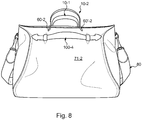
- FIGS 7 to 11 represent an example of a bag comprising a retractable handle such as that described above, with two identical ends. It more specifically comprises a first retractable handle, referenced 10-1 on a first blank 71-1, and a second retractable handle, referenced 10-2 on a second blank 71-2.
- the second retractable handle 10-2 is thus visible from an outside face of the blank 71-2 and the first retractable handle 10-1 is visible from an inner face of the first blank 71-1, opposite the second blank 71-2, through an opening 70 of the bag revealing the sliding system.
- the bag is largely flexible.
- the bottom may be flexible, rigid, or semi-rigid. It is mainly composed of the first blank 71-1 and the second blank 71-2, preferably identical, each having an edge 72-1, 72-2 defining an opening 70 through which it is possible to access a contents of the bag .
- first retractable handle 10-1 is positioned on a first side of the opening 70 to access a contents of the bag and the second retractable handle 10-2 is positioned on a second side of the opening 70 .
- the elements relating to the first retractable handle 10-1 are indicated by the same reference numerals as those used for the description of the elements represented on the Figures 2 to 6 , with the suffix "-1", and the elements relating to the second retractable handle 10-2 are indicated by the same numerical references as before with the suffix "-2".
- the description applies generically to an element, whatever the retractable handle to which it belongs, it is indicated without suffix.
- the first blank 71-1 thus forms the support 50-1 of the first retractable handle 10-1.
- the first blank 71-1 has a first slot 60-1, and a second slot 60'-1.
- the flexible loop 20-1 passes through the first slot 60-1 on the one hand and the second slot 60'-1 on the other hand. It comprises the first part 21-1 on the inner side 52-1 of the support 50-1 within the first slot 60-1, the second part 22-1 on the outer face 51-1 of the support 50-1 between the first slot 60-1 and the second slot 60'-1 and a third portion 21'-1 inner side 52-1 of the support 50-1 below the second slot 60'-1.
- the first portion 21-1 of the loop 20-1 comprises a first loop 30-1 and the second portion 21'-1 of the loop 20-1 has a second loop 30'-1.
- a first guide lug 40-1 and a second guide lug 40'-1 are arranged at least partly on the inner face 52-1 of the support 50-1.
- the first guide lug 40-1 passes through the first passer 30-1 of the first portion 21-1 of the handle 20-1 and the second guide lug 40'-1 passes through the second lead 30'-1 of the third part 21'-1 of Cove 20-1.
- the first retractable handle 10-1 comprises a first stop which is here formed by a protrusion 43-1 of the first guide lug 40-1 and a second abutment which is here formed by a protuberance 43 ' -1 of the second guide lug 40'-1.
- the handle 20-1 is configured to take either a carry position or a retracted position.
- the first passer 30-1 of the first portion 21-1 of the handle 20-1 is in contact with the first stop and the second pass 30'-1 of the third portion 21'-1 of the loop 20-1 is in contact with the second stop.
- the second portion 22-1 of the handle 20-1 substantially matches the outer face 51-1 of the support 50-1.
- the handle 20-1 then moves from the carrying position to the retracted position by a sliding of the handle 20-1 in the first slot 60-1 and the second slot 60'-1 and a sliding of the first passer 30- 1 of the first portion 21-1 of the loop 20-1 on the first guide lug 40-1 and the second loop 30'-1 of the third portion 21'-1 of the loop 20-1 on the second guide tab 40'-1.
- the first guide lug 40-1 and the second guide lug 40'-1 of the first retractable handle 10-1 are preferably positioned in the extension of one another so that the handle 20-1 retains a same longitudinal axis as it moves from the carrying position to the retracted position. In addition, they are advantageously positioned parallel to the edge 72-1 of the blank 71-1, which makes it possible to structure the edge 72-1 of the opening 70.
- the second retractable handle 10-2 is here identical to the first retractable handle 10-1 (the description thereof therefore applies to the retractable handle 10-2 by replacing the suffix "-1" by the suffix "-2 ").
- a positioning of the retractable handles 10 parallel to each of the edges 72 of the opening 70, in particular in the retracted position, makes it possible to structure the edges 72 and thus to contribute to maintaining the opening 70 in the closed position.
- the bag further comprises a third additional handle 100-3 and a fourth additional handle 100-4.
- the third additional handle 100-3 has a handle 200-3 and the fourth additional handle 100-4 has a handle 200-4.
- the additional handles 100 may be standard handles, for example similar to that illustrated on the figure 1 . However, they can be of any type, in particular according to the retractable handle according to embodiments of the invention, similar or different.
- each of the additional handles 100 is disposed on a blank 71 so that on each blank 71 a retractable handle 10 is located between an additional handle 100 and an edge 72 of the opening 70.
- the retractable handles 10 form so-called internal handles and the additional handles 100 form so-called external handles.
- internal is meant here the fact that the handle is positioned between another handle and the opening of the bag (and not the fact that the handle would be located inside the bag).
- the inner handles are thus high handles and the outer handles of the low handles when the bag is carried by the internal handles.
- the length of the outer part of the handles of the internal handles (in the carrying position) is advantageously greater than the length of the handles of the external handles, especially for ergonomic reasons.
- the length of the internal handles allows in particular a worn "hollow arm”.
- the illustrated bag thus has four handles, two internal and two external. It is thus configured to have a volume, said large volume, when the bag is carried by the internal handles, and a volume, said small volume, when the bag is carried by the external handles.
- the volume of the bag is thus adjustable according to the needs.
- a bag as described above is made at least partially of leather, imitation leather, fabric or any other flexible material or in any assembly of such materials.
- it further comprises a shoulder strap 80 conferring another option to carry the bag.
Landscapes
- Purses, Travelling Bags, Baskets, Or Suitcases (AREA)
Claims (14)
- Einschiebbarer Griff (10) für einen Lederwaren- oder Gepäckartikel umfassend:- einen Träger (50), der eine Außenseite (51), eine Innenseite (52) und mindestens einen durchquerenden Schlitz (60) umfasst,- einen weichen Henkel (20), der den mindestens einen Schlitz (60) durchquert und mindestens einen ersten Teil (21) an der Innenseite (52) des Trägers (50) und einen zweiten Teil (22) an der Außenseite (51) des Trägers (50) umfasst, wobei der erste Teil (21) des Henkels (20) mindestens eine Schlaufe (30) umfasst, wobei die Schlaufe (30) an einem freien Ende des ersten Teils (21) des Henkels (20) angeordnet ist,- mindestens eine zumindest teilweise an der Innenseite (52) des Trägers (50) angeordnete mit der mindestens einen Schlaufe (30) des ersten Teils (21) des Henkels (20) zusammenwirkende Führungslasche (40), und- mindestens einen Anschlag,wobei der Henkel (20) ausgebildet ist, einen von mindestens zwei Positionen einzunehmen:- eine Trageposition, in welcher die mindestens eine Schlaufe (30) des ersten Teils (21) des Henkels (20) in Kontakt mit dem mindestens einen Anschlag ist, und- eine eingeschobene Position, in der sich der zweite Teil (22) des Henkels (20) im Wesentlichen an die Außenseite (51) des Trägers (50) anschmiegt,wobei der Henkel (20) von der Trageposition zur eingeschobenen Position durch Einschieben der mindestens einen Schlaufe (30) des ersten Teils (21) des Henkels (20) auf der mindestens einen Führungslasche (40) wechselt,
dadurch gekennzeichnet, dass die Schlaufe (30) die Führungslasche (40) umgibt. - Einschiebbarer Griff (10) nach Anspruch 1, wobei der mindestens eine Anschlag zumindest teilweise durch den mindestens einen Schlitz (60) ausgebildet ist.
- Einschiebbarer Griff (10) nach Anspruch 1, wobei der mindestens eine Anschlag zumindest teilweise durch einen Vorsprung (43) der mindestens einen Führungslasche (40) ausgebildet ist.
- Einschiebbarer Griff (10) nach Anspruch 3, wobei der Vorsprung (43) der mindestens einen Führungslasche (40) in der Nähe des mindestens einen Schlitzes (60) ausgebildet ist.
- Einschiebbarer Griff (10) nach einem der Ansprüche 1 bis 4, wobei mindestens ein Teil (45) der mindestens einen Führungslasche (40), welcher mit der mindestens einen Schlaufe (30) zusammenwirkt, parallel zur mindestens einen Innenseite (52) des Trägers (50) ist.
- Einschiebbarer Griff (10) nach einem der Ansprüche 1 bis 5, wobei der Henkel (20), der Träger (50) und der mindestens eine Führungslasche (40) zumindest teilweise aus Leder bestehen.
- Einschiebbarer Griff (10) nach einem der Ansprüche 1 bis 6, wobei:- der Träger (50) mindestens einen durchquerenden Schlitz (60), welcher einen ersten Schlitz bildet, und einen zweiten durchquerenden Schlitz (60') umfasst,- der weiche Henkel (20) einerseits den ersten Schlitz (60) und andererseits den zweiten Schlitz (60') durchquert und einen ersten Teil (21) an der Innenseite (52) des Trägers (50) unterhalb des ersten Schlitzes (60), einen zweiten Teil (22) an der Außenseite (51) des Trägers (50) zwischen dem ersten Schlitz (60) und dem zweiten Schlitz (60') und einen ersten Teil (21') an der Innenseite (52) des Trägers (50) unterhalb des zweiten Schlitzes (60') umfasst, wobei der erste Teil (21) des Henkels (20) mindestens eine eine erste Schlaufe (30) bildende Schlaufe (30) umfasst, und wobei der dritte Teil (21') des Henkels (20) mindestens eine eine zweite Schlaufe (30') bildende Schlaufe (30') umfasst,- wobei die mindestens eine zumindest teilweise an der Innenseite (52) des Trägers (50) angeordnete Führungslasche (40) eine erste Führungslasche (40) bildet und eine zweite Führungslasche (40') zumindest teilweise an der Innenseite (52) des Trägers (50) angeordnet ist, wobei die erste Führungslasche (40) mit der ersten Schlaufe (30) des ersten Teils (21) des Henkels (20) zusammenwirkt, und wobei die zweite Führungslasche (40') mit der zweiten Schlaufe (30') des dritten Teils (21') des Henkels (20) zusammenwirkt, und- wobei der mindestens eine Anschlag einen ersten Anschlag und einen zweiten Anschlag bildet, wobei der Henkel (20) ausgebildet ist, einen von mindestens zwei Positionen einzunehmen:- die Trageposition, in der die erste Schlaufe (30) des ersten Teils (21) des Henkels (20) in Kontakt mit dem ersten Anschlag ist und in der die zweite Schlaufe (30') des dritten Teils (21') des Henkels (20) in Kontakt mit dem zweiten Anschlag ist, und- die eingeschobene Position, in der sich der zweite Teil (22) des Henkels (20) im Wesentlichen an die Außenseite (51) des Trägers (50) anschmiegt,wobei der Henkel (20) von der Trageposition zur eingeschobenen Position durch Einschieben der ersten Schlaufe (30) des ersten Teils (21) des Henkels (20) auf der ersten Führungslasche (40) und der zweiten Schlaufe (30') des dritten Teils (21') des Henkels (20) auf der zweiten Führungslasche (40') wechselt.
- Tasche, welche zumindest teilweise weich ist, umfassend wenigstens einen einschiebbaren Griff (10) nach einem der Ansprüche 1 bis 7.
- Tasche nach Anspruch 8, wobei mindestens ein einschiebbarer Griff (10) einen auf einer ersten Seite einer Öffnung (70) angeordneten ersten einschiebbaren Griff (10-1) bildet, welcher den Zugriff auf einen Inhalt der Tasche ermöglicht, wobei die Tasche ferner mindestens einen auf einer zweiten Seite der Öffnung (70) angeordneten zweiten einschiebbaren Griff (10-2) nach einem der Ansprüche 1 bis 7 umfasst.
- Tasche nach Anspruch 9, wobei der erste einschiebbare Griff (10-1) und der zweite einschiebbare Griff (10-2) jeweils parallel zu einem Rand (72-1, 72-2) der Öffnung (70) sind.
- Tasche nach einem der Ansprüche 8 bis 10, ferner umfassend zwei zusätzliche Griffe (100), die als dritter Griff (100-3) und vierter Griff (100-4) bezeichnet werden.
- Tasche nach dem von Anspruch 9 abhängigen Anspruch 11, wobei der erste einschiebbare Griff (10-1) zwischen dem dritten Griff (100-3) und der Öffnung (70) angeordnet ist, und der zweite einschiebbare Griff (10-2) zwischen dem vierten Griff (100-4) und der Öffnung (70) angeordnet ist.
- Tasche nach Anspruch 12, wobei der Henkel (20-1) des ersten einschiebbaren Griffs (10-1) und der Henkel (20-2) des zweiten einschiebbaren Griffs (10-2) eine Länge größer oder gleich einer Länge eines Henkels (200-3) des dritten Griffs (100-3) und eines Henkels des vierten Griffs (100-4) aufweisen.
- Tasche nach einem der Ansprüche 12 und 13, wobei der Henkel (20-1) des ersten einschiebbaren Griffs (10-1) und der Henkel (20-2) des zweiten einschiebbaren Griffs (10-2) die eingeschobene Position in einer Position der vom dritten Griff (100-3) und vierten Griff (100-4) getragenen Tasche einnehmen.
Applications Claiming Priority (1)
| Application Number | Priority Date | Filing Date | Title |
|---|---|---|---|
| FR1356498A FR3007950B1 (fr) | 2013-07-03 | 2013-07-03 | Poignee souple retractable |
Publications (3)
| Publication Number | Publication Date |
|---|---|
| EP2829191A2 EP2829191A2 (de) | 2015-01-28 |
| EP2829191A3 EP2829191A3 (de) | 2015-08-12 |
| EP2829191B1 true EP2829191B1 (de) | 2018-04-11 |
Family
ID=49212906
Family Applications (1)
| Application Number | Title | Priority Date | Filing Date |
|---|---|---|---|
| EP14175324.4A Active EP2829191B1 (de) | 2013-07-03 | 2014-07-01 | Weicher einziehbarer Griff |
Country Status (5)
| Country | Link |
|---|---|
| US (1) | US9924771B2 (de) |
| EP (1) | EP2829191B1 (de) |
| JP (1) | JP6510190B2 (de) |
| CN (1) | CN104273907B (de) |
| FR (1) | FR3007950B1 (de) |
Families Citing this family (2)
| Publication number | Priority date | Publication date | Assignee | Title |
|---|---|---|---|---|
| KR101672670B1 (ko) * | 2016-02-15 | 2016-11-03 | 김상윤 | 낚시용 가방 |
| CN210461278U (zh) * | 2019-05-24 | 2020-05-05 | 富港电子(昆山)有限公司 | 手部固定带 |
Family Cites Families (21)
| Publication number | Priority date | Publication date | Assignee | Title |
|---|---|---|---|---|
| US1587982A (en) * | 1925-10-28 | 1926-06-08 | Nover Morris | Hand-bag handle |
| GB329504A (en) * | 1929-05-15 | 1930-05-22 | Walter James Hill | Improvements relating to handles for bags and like portable articles |
| US1958587A (en) * | 1929-11-13 | 1934-05-15 | Columbia Phonograph Co Inc | Carrying handle for portable gramophones or the like |
| US2011880A (en) * | 1934-06-14 | 1935-08-20 | Stein Leo | Disappearing handle |
| FR850259A (fr) * | 1938-03-18 | 1939-12-12 | Perfectionnements aux poignées pour sacs, valises, etc. | |
| US2195028A (en) * | 1939-01-21 | 1940-03-26 | Finkelstein William | Handle and loop |
| US2248328A (en) * | 1939-05-19 | 1941-07-08 | Bechik Michael | Flexible mattress handle |
| US2987151A (en) * | 1959-09-14 | 1961-06-06 | Philadelphia Brief Case Compan | Collapsible flat-lying handle |
| US3113651A (en) * | 1962-11-20 | 1963-12-10 | Philadelphia Handle Company | Collapsible flush-lying handle |
| US3340563A (en) * | 1965-01-29 | 1967-09-12 | Gen Electric | Retractable handle for portable television receiver |
| US4435029A (en) * | 1981-07-06 | 1984-03-06 | Rockwell International Corporation | Slide lock handle |
| GB2214490B (en) * | 1988-01-09 | 1991-09-18 | Spartan Luggage Co Ltd | Improvements relating to handles of luggage cases |
| US4825506A (en) * | 1988-07-14 | 1989-05-02 | Nathan Weltz | Biblecase and bookcover |
| US6536078B2 (en) * | 2001-07-18 | 2003-03-25 | James Tsai | Retractable handle for a case |
| US6585090B2 (en) * | 2001-10-26 | 2003-07-01 | Stephen C. Harvey | Stackable interlocking carrying case for a portable computer |
| CN2855170Y (zh) * | 2005-12-23 | 2007-01-10 | 刘轶杰 | 一种拎包 |
| CN201384157Y (zh) * | 2009-01-16 | 2010-01-20 | 冯俊 | 便携式购物袋 |
| US7708141B1 (en) * | 2009-08-07 | 2010-05-04 | Huang James C | File holder with hanging mechanism |
| GB2479718B (en) * | 2010-04-13 | 2014-11-19 | Guy Francis Charles Cowdry | A carrying bag |
| US8439174B1 (en) * | 2011-01-26 | 2013-05-14 | Susan L. Miranda | Combined suitcase and cushion apparatus |
| US8950638B2 (en) * | 2012-09-25 | 2015-02-10 | Loopy Cases Llc | Finger loop for portable electronic device case |
-
2013
- 2013-07-03 FR FR1356498A patent/FR3007950B1/fr active Active
-
2014
- 2014-07-01 EP EP14175324.4A patent/EP2829191B1/de active Active
- 2014-07-02 US US14/322,071 patent/US9924771B2/en active Active
- 2014-07-02 CN CN201410312197.2A patent/CN104273907B/zh active Active
- 2014-07-02 JP JP2014137170A patent/JP6510190B2/ja active Active
Non-Patent Citations (1)
| Title |
|---|
| None * |
Also Published As
| Publication number | Publication date |
|---|---|
| US20150013860A1 (en) | 2015-01-15 |
| JP2015013120A (ja) | 2015-01-22 |
| CN104273907B (zh) | 2018-06-29 |
| CN104273907A (zh) | 2015-01-14 |
| EP2829191A2 (de) | 2015-01-28 |
| EP2829191A3 (de) | 2015-08-12 |
| FR3007950A1 (fr) | 2015-01-09 |
| JP6510190B2 (ja) | 2019-05-08 |
| US9924771B2 (en) | 2018-03-27 |
| FR3007950B1 (fr) | 2018-03-30 |
Similar Documents
| Publication | Publication Date | Title |
|---|---|---|
| FR2825589A1 (fr) | Gant de protection ambidextre | |
| EP1506724B1 (de) | Rucksack mit winkelbeweglichem Hüftgurt | |
| EP2829191B1 (de) | Weicher einziehbarer Griff | |
| EP1779744A2 (de) | Zusammenlegbarer Gebrauchsgegenstand | |
| FR2859358A1 (fr) | Ensemble formant bagage a roulettes | |
| EP3447002B1 (de) | Universal-verpackungsbahn | |
| EP3266332A1 (de) | Armbanduhr | |
| FR3022126B1 (fr) | Sac a dos | |
| EP2807943B1 (de) | Befestigungsvorrichtung eines Schulterriemens und einer Lasche am Körper einer Handtasche, Tasche, die eine solche Vorrichtung umfasst, und Herstellungsverfahren | |
| EP1428682B1 (de) | Bucheinband, -bindung oder -halter mit griff und/oder riemen | |
| EP3309410B1 (de) | Sack mit aufsatzverlängerung und verschlussklemme für sack mit aufsatzverlängerung | |
| FR2967709A1 (fr) | Conteneur, notamment de type tente ou abri, a double enveloppes souples reliees par un dispositif de liaison, et dispositif de liaison correspondant | |
| EP4230081B1 (de) | Schulterriemen für einen lederwarenartikel, lederwarenartikel mit dem schulterriemen und anordnung mit einem träger und dem daran befestigten artikel | |
| FR2868396A1 (fr) | Dispositif de conditionnement d'un article | |
| FR3001869A1 (fr) | Accessoire de maroquinerie montable et demontable | |
| EP1773153B1 (de) | Aufbewahrungsbeutel | |
| FR3115019A1 (fr) | Contenant portatif a ouverture amelioree | |
| CH712654A2 (fr) | Montre bracelet. | |
| FR2806890A1 (fr) | Bagage comportant au moins une poche accessible de l'exterieur | |
| WO2003078269A1 (fr) | Emballage pour la presentation d'un vetement et flan permettant la realisation d'un tel emballage______________________ | |
| FR2926243A1 (fr) | Dossier de classement | |
| FR3010419A1 (fr) | Dispositif pour la formation d'un noeud decoratif | |
| FR3039751A1 (fr) | Enveloppe de rangement d'un dispositif de protection contre le soleil ou les intemperies | |
| CA2908604A1 (fr) | Sac a provisions parallelepipedique rectangle repliable comportant des moyens de maintien dans son etat ouvert | |
| EP2756775A1 (de) | Schutzschale für tragbares Datenendgerät |
Legal Events
| Date | Code | Title | Description |
|---|---|---|---|
| 17P | Request for examination filed |
Effective date: 20140701 |
|
| AK | Designated contracting states |
Kind code of ref document: A2 Designated state(s): AL AT BE BG CH CY CZ DE DK EE ES FI FR GB GR HR HU IE IS IT LI LT LU LV MC MK MT NL NO PL PT RO RS SE SI SK SM TR |
|
| AX | Request for extension of the european patent |
Extension state: BA ME |
|
| PUAI | Public reference made under article 153(3) epc to a published international application that has entered the european phase |
Free format text: ORIGINAL CODE: 0009012 |
|
| PUAL | Search report despatched |
Free format text: ORIGINAL CODE: 0009013 |
|
| AK | Designated contracting states |
Kind code of ref document: A3 Designated state(s): AL AT BE BG CH CY CZ DE DK EE ES FI FR GB GR HR HU IE IS IT LI LT LU LV MC MK MT NL NO PL PT RO RS SE SI SK SM TR |
|
| AX | Request for extension of the european patent |
Extension state: BA ME |
|
| RIC1 | Information provided on ipc code assigned before grant |
Ipc: A45C 13/26 20060101ALI20150706BHEP Ipc: B65D 25/28 20060101ALI20150706BHEP Ipc: A45C 3/06 20060101AFI20150706BHEP |
|
| R17P | Request for examination filed (corrected) |
Effective date: 20160128 |
|
| RBV | Designated contracting states (corrected) |
Designated state(s): AL AT BE BG CH CY CZ DE DK EE ES FI FR GB GR HR HU IE IS IT LI LT LU LV MC MK MT NL NO PL PT RO RS SE SI SK SM TR |
|
| STAA | Information on the status of an ep patent application or granted ep patent |
Free format text: STATUS: EXAMINATION IS IN PROGRESS |
|
| 17Q | First examination report despatched |
Effective date: 20170117 |
|
| GRAP | Despatch of communication of intention to grant a patent |
Free format text: ORIGINAL CODE: EPIDOSNIGR1 |
|
| STAA | Information on the status of an ep patent application or granted ep patent |
Free format text: STATUS: GRANT OF PATENT IS INTENDED |
|
| INTG | Intention to grant announced |
Effective date: 20171108 |
|
| GRAS | Grant fee paid |
Free format text: ORIGINAL CODE: EPIDOSNIGR3 |
|
| GRAA | (expected) grant |
Free format text: ORIGINAL CODE: 0009210 |
|
| STAA | Information on the status of an ep patent application or granted ep patent |
Free format text: STATUS: THE PATENT HAS BEEN GRANTED |
|
| AK | Designated contracting states |
Kind code of ref document: B1 Designated state(s): AL AT BE BG CH CY CZ DE DK EE ES FI FR GB GR HR HU IE IS IT LI LT LU LV MC MK MT NL NO PL PT RO RS SE SI SK SM TR |
|
| REG | Reference to a national code |
Ref country code: GB Ref legal event code: FG4D Free format text: NOT ENGLISH |
|
| REG | Reference to a national code |
Ref country code: CH Ref legal event code: EP |
|
| REG | Reference to a national code |
Ref country code: AT Ref legal event code: REF Ref document number: 987055 Country of ref document: AT Kind code of ref document: T Effective date: 20180415 |
|
| REG | Reference to a national code |
Ref country code: IE Ref legal event code: FG4D Free format text: LANGUAGE OF EP DOCUMENT: FRENCH |
|
| REG | Reference to a national code |
Ref country code: DE Ref legal event code: R096 Ref document number: 602014023597 Country of ref document: DE |
|
| REG | Reference to a national code |
Ref country code: FR Ref legal event code: PLFP Year of fee payment: 5 |
|
| REG | Reference to a national code |
Ref country code: NL Ref legal event code: MP Effective date: 20180411 |
|
| REG | Reference to a national code |
Ref country code: LT Ref legal event code: MG4D |
|
| PG25 | Lapsed in a contracting state [announced via postgrant information from national office to epo] |
Ref country code: NL Free format text: LAPSE BECAUSE OF FAILURE TO SUBMIT A TRANSLATION OF THE DESCRIPTION OR TO PAY THE FEE WITHIN THE PRESCRIBED TIME-LIMIT Effective date: 20180411 |
|
| PG25 | Lapsed in a contracting state [announced via postgrant information from national office to epo] |
Ref country code: NO Free format text: LAPSE BECAUSE OF FAILURE TO SUBMIT A TRANSLATION OF THE DESCRIPTION OR TO PAY THE FEE WITHIN THE PRESCRIBED TIME-LIMIT Effective date: 20180711 Ref country code: FI Free format text: LAPSE BECAUSE OF FAILURE TO SUBMIT A TRANSLATION OF THE DESCRIPTION OR TO PAY THE FEE WITHIN THE PRESCRIBED TIME-LIMIT Effective date: 20180411 Ref country code: LT Free format text: LAPSE BECAUSE OF FAILURE TO SUBMIT A TRANSLATION OF THE DESCRIPTION OR TO PAY THE FEE WITHIN THE PRESCRIBED TIME-LIMIT Effective date: 20180411 Ref country code: BG Free format text: LAPSE BECAUSE OF FAILURE TO SUBMIT A TRANSLATION OF THE DESCRIPTION OR TO PAY THE FEE WITHIN THE PRESCRIBED TIME-LIMIT Effective date: 20180711 Ref country code: PL Free format text: LAPSE BECAUSE OF FAILURE TO SUBMIT A TRANSLATION OF THE DESCRIPTION OR TO PAY THE FEE WITHIN THE PRESCRIBED TIME-LIMIT Effective date: 20180411 Ref country code: ES Free format text: LAPSE BECAUSE OF FAILURE TO SUBMIT A TRANSLATION OF THE DESCRIPTION OR TO PAY THE FEE WITHIN THE PRESCRIBED TIME-LIMIT Effective date: 20180411 Ref country code: SE Free format text: LAPSE BECAUSE OF FAILURE TO SUBMIT A TRANSLATION OF THE DESCRIPTION OR TO PAY THE FEE WITHIN THE PRESCRIBED TIME-LIMIT Effective date: 20180411 Ref country code: AL Free format text: LAPSE BECAUSE OF FAILURE TO SUBMIT A TRANSLATION OF THE DESCRIPTION OR TO PAY THE FEE WITHIN THE PRESCRIBED TIME-LIMIT Effective date: 20180411 |
|
| PG25 | Lapsed in a contracting state [announced via postgrant information from national office to epo] |
Ref country code: RS Free format text: LAPSE BECAUSE OF FAILURE TO SUBMIT A TRANSLATION OF THE DESCRIPTION OR TO PAY THE FEE WITHIN THE PRESCRIBED TIME-LIMIT Effective date: 20180411 Ref country code: LV Free format text: LAPSE BECAUSE OF FAILURE TO SUBMIT A TRANSLATION OF THE DESCRIPTION OR TO PAY THE FEE WITHIN THE PRESCRIBED TIME-LIMIT Effective date: 20180411 Ref country code: GR Free format text: LAPSE BECAUSE OF FAILURE TO SUBMIT A TRANSLATION OF THE DESCRIPTION OR TO PAY THE FEE WITHIN THE PRESCRIBED TIME-LIMIT Effective date: 20180712 Ref country code: HR Free format text: LAPSE BECAUSE OF FAILURE TO SUBMIT A TRANSLATION OF THE DESCRIPTION OR TO PAY THE FEE WITHIN THE PRESCRIBED TIME-LIMIT Effective date: 20180411 |
|
| REG | Reference to a national code |
Ref country code: AT Ref legal event code: MK05 Ref document number: 987055 Country of ref document: AT Kind code of ref document: T Effective date: 20180411 |
|
| PG25 | Lapsed in a contracting state [announced via postgrant information from national office to epo] |
Ref country code: PT Free format text: LAPSE BECAUSE OF FAILURE TO SUBMIT A TRANSLATION OF THE DESCRIPTION OR TO PAY THE FEE WITHIN THE PRESCRIBED TIME-LIMIT Effective date: 20180813 |
|
| REG | Reference to a national code |
Ref country code: DE Ref legal event code: R097 Ref document number: 602014023597 Country of ref document: DE |
|
| PG25 | Lapsed in a contracting state [announced via postgrant information from national office to epo] |
Ref country code: DK Free format text: LAPSE BECAUSE OF FAILURE TO SUBMIT A TRANSLATION OF THE DESCRIPTION OR TO PAY THE FEE WITHIN THE PRESCRIBED TIME-LIMIT Effective date: 20180411 Ref country code: SK Free format text: LAPSE BECAUSE OF FAILURE TO SUBMIT A TRANSLATION OF THE DESCRIPTION OR TO PAY THE FEE WITHIN THE PRESCRIBED TIME-LIMIT Effective date: 20180411 Ref country code: CZ Free format text: LAPSE BECAUSE OF FAILURE TO SUBMIT A TRANSLATION OF THE DESCRIPTION OR TO PAY THE FEE WITHIN THE PRESCRIBED TIME-LIMIT Effective date: 20180411 Ref country code: RO Free format text: LAPSE BECAUSE OF FAILURE TO SUBMIT A TRANSLATION OF THE DESCRIPTION OR TO PAY THE FEE WITHIN THE PRESCRIBED TIME-LIMIT Effective date: 20180411 Ref country code: EE Free format text: LAPSE BECAUSE OF FAILURE TO SUBMIT A TRANSLATION OF THE DESCRIPTION OR TO PAY THE FEE WITHIN THE PRESCRIBED TIME-LIMIT Effective date: 20180411 Ref country code: AT Free format text: LAPSE BECAUSE OF FAILURE TO SUBMIT A TRANSLATION OF THE DESCRIPTION OR TO PAY THE FEE WITHIN THE PRESCRIBED TIME-LIMIT Effective date: 20180411 |
|
| PLBE | No opposition filed within time limit |
Free format text: ORIGINAL CODE: 0009261 |
|
| STAA | Information on the status of an ep patent application or granted ep patent |
Free format text: STATUS: NO OPPOSITION FILED WITHIN TIME LIMIT |
|
| PG25 | Lapsed in a contracting state [announced via postgrant information from national office to epo] |
Ref country code: SM Free format text: LAPSE BECAUSE OF FAILURE TO SUBMIT A TRANSLATION OF THE DESCRIPTION OR TO PAY THE FEE WITHIN THE PRESCRIBED TIME-LIMIT Effective date: 20180411 |
|
| REG | Reference to a national code |
Ref country code: CH Ref legal event code: PL |
|
| 26N | No opposition filed |
Effective date: 20190114 |
|
| PG25 | Lapsed in a contracting state [announced via postgrant information from national office to epo] |
Ref country code: LU Free format text: LAPSE BECAUSE OF NON-PAYMENT OF DUE FEES Effective date: 20180701 Ref country code: MC Free format text: LAPSE BECAUSE OF FAILURE TO SUBMIT A TRANSLATION OF THE DESCRIPTION OR TO PAY THE FEE WITHIN THE PRESCRIBED TIME-LIMIT Effective date: 20180411 |
|
| REG | Reference to a national code |
Ref country code: BE Ref legal event code: MM Effective date: 20180731 |
|
| REG | Reference to a national code |
Ref country code: IE Ref legal event code: MM4A |
|
| PG25 | Lapsed in a contracting state [announced via postgrant information from national office to epo] |
Ref country code: IE Free format text: LAPSE BECAUSE OF NON-PAYMENT OF DUE FEES Effective date: 20180701 Ref country code: CH Free format text: LAPSE BECAUSE OF NON-PAYMENT OF DUE FEES Effective date: 20180731 Ref country code: LI Free format text: LAPSE BECAUSE OF NON-PAYMENT OF DUE FEES Effective date: 20180731 |
|
| PG25 | Lapsed in a contracting state [announced via postgrant information from national office to epo] |
Ref country code: SI Free format text: LAPSE BECAUSE OF FAILURE TO SUBMIT A TRANSLATION OF THE DESCRIPTION OR TO PAY THE FEE WITHIN THE PRESCRIBED TIME-LIMIT Effective date: 20180411 Ref country code: BE Free format text: LAPSE BECAUSE OF NON-PAYMENT OF DUE FEES Effective date: 20180731 |
|
| PG25 | Lapsed in a contracting state [announced via postgrant information from national office to epo] |
Ref country code: MT Free format text: LAPSE BECAUSE OF FAILURE TO SUBMIT A TRANSLATION OF THE DESCRIPTION OR TO PAY THE FEE WITHIN THE PRESCRIBED TIME-LIMIT Effective date: 20180411 |
|
| PG25 | Lapsed in a contracting state [announced via postgrant information from national office to epo] |
Ref country code: TR Free format text: LAPSE BECAUSE OF FAILURE TO SUBMIT A TRANSLATION OF THE DESCRIPTION OR TO PAY THE FEE WITHIN THE PRESCRIBED TIME-LIMIT Effective date: 20180411 |
|
| PG25 | Lapsed in a contracting state [announced via postgrant information from national office to epo] |
Ref country code: HU Free format text: LAPSE BECAUSE OF FAILURE TO SUBMIT A TRANSLATION OF THE DESCRIPTION OR TO PAY THE FEE WITHIN THE PRESCRIBED TIME-LIMIT; INVALID AB INITIO Effective date: 20140701 |
|
| PG25 | Lapsed in a contracting state [announced via postgrant information from national office to epo] |
Ref country code: MK Free format text: LAPSE BECAUSE OF NON-PAYMENT OF DUE FEES Effective date: 20180411 Ref country code: CY Free format text: LAPSE BECAUSE OF FAILURE TO SUBMIT A TRANSLATION OF THE DESCRIPTION OR TO PAY THE FEE WITHIN THE PRESCRIBED TIME-LIMIT Effective date: 20180411 |
|
| PG25 | Lapsed in a contracting state [announced via postgrant information from national office to epo] |
Ref country code: IS Free format text: LAPSE BECAUSE OF FAILURE TO SUBMIT A TRANSLATION OF THE DESCRIPTION OR TO PAY THE FEE WITHIN THE PRESCRIBED TIME-LIMIT Effective date: 20180811 |
|
| P01 | Opt-out of the competence of the unified patent court (upc) registered |
Effective date: 20230512 |
|
| PGFP | Annual fee paid to national office [announced via postgrant information from national office to epo] |
Ref country code: DE Payment date: 20250728 Year of fee payment: 12 |
|
| PGFP | Annual fee paid to national office [announced via postgrant information from national office to epo] |
Ref country code: IT Payment date: 20250728 Year of fee payment: 12 |
|
| PGFP | Annual fee paid to national office [announced via postgrant information from national office to epo] |
Ref country code: GB Payment date: 20250703 Year of fee payment: 12 |
|
| PGFP | Annual fee paid to national office [announced via postgrant information from national office to epo] |
Ref country code: FR Payment date: 20250707 Year of fee payment: 12 |