EP2828943B1 - Leitungsaufnahmeelement - Google Patents
Leitungsaufnahmeelement Download PDFInfo
- Publication number
- EP2828943B1 EP2828943B1 EP13715126.2A EP13715126A EP2828943B1 EP 2828943 B1 EP2828943 B1 EP 2828943B1 EP 13715126 A EP13715126 A EP 13715126A EP 2828943 B1 EP2828943 B1 EP 2828943B1
- Authority
- EP
- European Patent Office
- Prior art keywords
- pipe
- receiving element
- cover
- base
- webs
- Prior art date
- Legal status (The legal status is an assumption and is not a legal conclusion. Google has not performed a legal analysis and makes no representation as to the accuracy of the status listed.)
- Active
Links
Images


Classifications
-
- H—ELECTRICITY
- H02—GENERATION; CONVERSION OR DISTRIBUTION OF ELECTRIC POWER
- H02G—INSTALLATION OF ELECTRIC CABLES OR LINES, OR OF COMBINED OPTICAL AND ELECTRIC CABLES OR LINES
- H02G3/00—Installations of electric cables or lines or protective tubing therefor in or on buildings, equivalent structures or vehicles
- H02G3/02—Details
- H02G3/04—Protective tubing or conduits, e.g. cable ladders or cable troughs
- H02G3/0462—Tubings, i.e. having a closed section
- H02G3/0487—Tubings, i.e. having a closed section with a non-circular cross-section
-
- H—ELECTRICITY
- H02—GENERATION; CONVERSION OR DISTRIBUTION OF ELECTRIC POWER
- H02G—INSTALLATION OF ELECTRIC CABLES OR LINES, OR OF COMBINED OPTICAL AND ELECTRIC CABLES OR LINES
- H02G3/00—Installations of electric cables or lines or protective tubing therefor in or on buildings, equivalent structures or vehicles
- H02G3/02—Details
- H02G3/04—Protective tubing or conduits, e.g. cable ladders or cable troughs
- H02G3/0437—Channels
-
- F—MECHANICAL ENGINEERING; LIGHTING; HEATING; WEAPONS; BLASTING
- F16—ENGINEERING ELEMENTS AND UNITS; GENERAL MEASURES FOR PRODUCING AND MAINTAINING EFFECTIVE FUNCTIONING OF MACHINES OR INSTALLATIONS; THERMAL INSULATION IN GENERAL
- F16L—PIPES; JOINTS OR FITTINGS FOR PIPES; SUPPORTS FOR PIPES, CABLES OR PROTECTIVE TUBING; MEANS FOR THERMAL INSULATION IN GENERAL
- F16L3/00—Supports for pipes, cables or protective tubing, e.g. hangers, holders, clamps, cleats, clips, brackets
- F16L3/08—Supports for pipes, cables or protective tubing, e.g. hangers, holders, clamps, cleats, clips, brackets substantially surrounding the pipe, cable or protective tubing
- F16L3/12—Supports for pipes, cables or protective tubing, e.g. hangers, holders, clamps, cleats, clips, brackets substantially surrounding the pipe, cable or protective tubing comprising a member substantially surrounding the pipe, cable or protective tubing
- F16L3/13—Supports for pipes, cables or protective tubing, e.g. hangers, holders, clamps, cleats, clips, brackets substantially surrounding the pipe, cable or protective tubing comprising a member substantially surrounding the pipe, cable or protective tubing and engaging it by snap action
-
- H—ELECTRICITY
- H02—GENERATION; CONVERSION OR DISTRIBUTION OF ELECTRIC POWER
- H02G—INSTALLATION OF ELECTRIC CABLES OR LINES, OR OF COMBINED OPTICAL AND ELECTRIC CABLES OR LINES
- H02G3/00—Installations of electric cables or lines or protective tubing therefor in or on buildings, equivalent structures or vehicles
- H02G3/02—Details
- H02G3/04—Protective tubing or conduits, e.g. cable ladders or cable troughs
- H02G3/0437—Channels
- H02G3/045—Channels provided with perforations or slots permitting introduction or exit of wires
-
- H—ELECTRICITY
- H02—GENERATION; CONVERSION OR DISTRIBUTION OF ELECTRIC POWER
- H02G—INSTALLATION OF ELECTRIC CABLES OR LINES, OR OF COMBINED OPTICAL AND ELECTRIC CABLES OR LINES
- H02G3/00—Installations of electric cables or lines or protective tubing therefor in or on buildings, equivalent structures or vehicles
- H02G3/02—Details
- H02G3/04—Protective tubing or conduits, e.g. cable ladders or cable troughs
- H02G3/0456—Ladders or other supports
Definitions
- the invention consists of a cable receiving element with a base, at least two side parts extending from the base in the same direction, and with a cover closing at least the free ends of the side parts to form at least one chamber receiving a conduit.
- Cable receiving elements are off FR 1352504 A and WO 2009/073765 A1 known.
- the invention is therefore an object of the invention to provide a cable receiving element of the type mentioned above, with the simplest technical means on the spot in the equipment of racks, tables or the like allows an adjustment of the cable receiving elements with very little effort and at the same time the creation time for such buildings significantly reduce.
- the gist of the invention is to secure the required line receiving elements in place to allow the preferably electrical, pneumatic or liquid conducting lines or the like by simply forcing these lines into the chamber due to the opening capacity of the two lips.
- these cable receiving elements can be easily cut to length with a pair of scissors.
- the fastening device is an adhesive layer, with which the line receiving element can be attached at any desired locations.
- a particularly strong and simple way of fixing the cable receiving element is quite easy for profile bars with undercut grooves.
- the at least one projection on the cable receiving element runs on the base in such a way that the cable receiving element is adapted to the outer contour of a profile bar.
- profiled bars with undercut grooves which have a rectangular shape. It is then possible to provide at least two projections on the longitudinal side of these profiles. If this is the case, it is particularly advantageous if at least two projections are arranged on the base.
- the base, the webs, the cover and the projection are integrally made of an elastic material.
- the base, lands, cover and protrusion are integrally formed of different materials, with the covering material and the protruding material being more elastic than the web material.
- the covering material at the beginning of the web has the greatest thickness, which becomes ever smaller in the direction of the base in relation to the thickness of the web.
- the cover material also encloses this on the outer surfaces of the two outer webs. Mainly in dependence on the applied pressure for fastening the line receiving elements, it is advantageous if the thickness of the webs deviates from the strengths of the cover and the base.
- FIG. 4 a base 12 on. From this base 12 extending in this embodiment in the same direction four side parts 14 which form three chambers 18 for receiving a respective line 16 in this constellation.
- the three chambers 18 are closed on the base 12 opposite side with a so-called cover 20.
- the areas of the chambers 18 are provided with movable lips 26. Since the material for the line receiving elements 10 consists of at least one plastic, these lips 26 are movable both in the direction of the chamber 18 and to the outside.
- the base 12 may be provided with an adhesive strip for attaching the cable receiving element 10 in order to attach this cable receiving element 10 at the desired position, which of course must be suitable for an adhesive connection, another mounting option has been selected.
- connection possibility which are introduced in this case in undercut grooves 34 of a profile bar 32.
- This type of connection is a projection 28 which, due to its cross-sectional shape in the longitudinal direction, holds elastically latching on the undercut 30 of the undercut groove 34.
- lines 16 which are electrical lines in this case, can be pressed in the direction of the chambers 18 by attaching the line receiving elements or the line receiving element 10 by placing on a longitudinal slot 24 and firm impressions by displacing the lips 26.
- the inserted cable 16 can easily be removed and replaced by a new or different cable 16.
- FIG. 2 shown cross-section but also on the basis of in FIG. 4 shown cross-section of the second embodiment, it can be seen that by varying the individual wall thicknesses different spring voltages or so-called spring constants in particular for the lips 26 by varying the wall thicknesses is possible.
- the thicknesses of the outer webs 14 are less than those of the two inner ones.
- the cover 20 In order to come back to a uniform thickness ratio seen in cross section, is in the second embodiment according to FIG. 4 the cover 20 also arranged on the outer surfaces of the two outermost webs 14 enveloping to the base. This not only serves to protect the surface of the line receiving element 10, but also a uniform visual appearance.
- the cover material at the beginning of the web 14 has the greatest strength, which is in the direction of the base 12 in relation to the thickness of the web 14 is always lower. This has no optical cause, but serves to better adjust the spring constant of the webs 14 in interaction with the lips 26th
- the force on the lips 24 at the point at which a line 16 had emerged for a long time clearly increased.
- the reinforcements extend into the chambers 18 so as not to disturb the visual appearance. But it can also be arranged above the webs and outside on the cover 20, this reinforcement.
Landscapes
- Engineering & Computer Science (AREA)
- Architecture (AREA)
- Civil Engineering (AREA)
- Structural Engineering (AREA)
- General Engineering & Computer Science (AREA)
- Mechanical Engineering (AREA)
- Details Of Indoor Wiring (AREA)
- Laying Of Electric Cables Or Lines Outside (AREA)
- Insulating Bodies (AREA)
- Shaping Of Tube Ends By Bending Or Straightening (AREA)
- Lining Or Joining Of Plastics Or The Like (AREA)
- Infusion, Injection, And Reservoir Apparatuses (AREA)
Description
- Die Erfindung besteht aus einem Leitungsaufnahmeelement mit einer Basis, mindestens zwei sich von der Basis in gleicher Richtung erstreckenden Seitenteilen und mit einer mindestens die freien Enden der Seitenteile schließenden Abdeckung zur Ausbildung mindestens einer eine Leitung aufnehmenden Kammer.
- Im Zusammenhang mit dem Arbeitsplatzsystem der Anmelder ist ein Bedarf an Lösungen zum einfachen und optisch sauberen Verlegen von elektrischen, pneumatischen etc. Leitungen entstanden.
- Zwar bieten die Anmelder bereits verschiedene (Aluminium) Kabelkanäle und auch ein modulares System für Kabelkanäle an, nur bedürfen diese Produkte einer detaillierten Planung. Dies liegt daran, dass die starren Aluminiumkanäle nur auf einer entsprechenden Säge verarbeitet werden können, die auch zum Ablängen von Konstruktionsprofilen dient.
- Zusätzlich müssen zur Montage Bohrungen angebracht oder aufwendige Verbindungstechniken eingesetzt werden. Die gesägten Enden der Profile sind steif und scharfkantig, was zusätzliche Bauelemente, wie zum Beispiel Kantenband oder Kabeldurchlässe oder ähnliches zum Schutz der ein- und austretenden Leitungen erforderlich macht.
- Leitungsaufnahmeelemente sind aus
FR 1352504 A WO 2009/073765 A1 bekannt. - Dieses deckt sich zwar mit den Wünschen der Kunden der Anmelder, nur entsteht der präzise Bedarf an Leitungsführungen üblicherweise erst bei Ausrüstung der Gestelle, Tische oder ähnliches. Somit müsste nach dem Bau des Grundgerüsts sozusagen "nachprojektiert" und die entsprechenden Kanäle anschließend zugeschnitten und bearbeitet werden.
- Dies erzeugt zusammen mit den qualitativ hochwertigen Produkten sehr hohe Kosten, welche erfahrungsgemäß von den meisten Anwendern gemieden werden. Nach derzeitigem Kenntnisstand ist aus dem allgemeinen Stand der Technik keine Lösung bekannt.
- Der Erfindung liegt daher die Aufgabe zugrunde, ein Leitungsaufnahmeelement der eingangs genannten Art anzugeben, das mit einfachsten technischen Mitteln an Ort und Stelle bei der Ausrüstung von Gestellen, Tische oder ähnlichem eine Anpassung der Leitungsaufnahmeelemente mit sehr geringem Aufwand ermöglicht und gleichzeitig die Erstellungszeit für derartige Bauten deutlich zu reduzieren.
- Diese Aufgabe wird bei einem Leitungsaufnahmeelement der eingangs genannt Art erfindungsgemäß durch die Merkmale des Anspruchs 1 gelöst.
- Der Kern der Erfindung besteht darin, die benötigten Leitungsaufnahmeelemente an Ort und Stelle zu befestigen, um die vorzugsweise elektrischen, pneumatischen oder Flüssigkeit führenden Leitungen oder ähnliches durch einfaches Eindrücken dieser Leitungen in die Kammer aufgrund des Öffnungsvermögens der beiden Lippen zu ermöglichen. Außerdem können diese Leitungsaufnahmeelemente einfach mit einer Schere abgelängt werden.
- Auf diese Art und Weise werden mehrere Punkte der Aufgabenstellung hier am Beispiel eines Aluminiumprofils mit hinterschnittenen Nuten gelöst:
- die Leitungen werden unsichtbar in einem geschlossenen Profil entlang der Gerüststreben geführt;
- die Befestigung erfolgt durch Aufkleben bzw. durch Eindrückung eines Vorsprunges in eine Nut des Aluminiumprofils ohne weitere Bearbeitung;
- die Leitungen können an beliebigen Stellen des Profils einund austreten, ohne das Profil zu beschädigen oder auch gar zu bearbeiten, wodurch diese Veränderungen der Ausrüstung einfacher und sauberer durchführbar sind;
- die Enden des Profils können - wie die Lippen - elastisch sein und daher die Notwendigkeit eines zusätzlichen Leitungsschutzes vermeiden;
- das Zuschneiden der erforderlichen Stücke kann von einem Handwerker während der Ausrüstung am Arbeitsort erfolgen, da keine Säge mehr erforderlich ist;
- die Verarbeitung ist spanlos und daher äußerst sauber;
- flache Winkel können auch durch die Elastizität des Werkstoffes überbrückt werden, ohne das Profil zu trennen; und
- die Leitungen werden in den getrennten Hohlräumen einzeln geführt, so dass sie jederzeit auch einzeln entfernt bzw. getauscht werden können, sie verheddern sich daher nicht ineinander wie in einem einzelnen Kanal.
- Wie bereits oben schon angedeutet, ist es möglich, dass die Befestigungseinrichtung eine Klebeschicht ist, mit der das Leitungsaufnahmeelement an beliebigen Stellen anbringbar ist.
- Erfindungsgemäß ist die Verwendung von entsprechenden Profilen, wenn die Befestigungseinrichtung mindestens ein an der Basis angeordneter und den Seitenteilen oder Stegen entgegengesetzt sich erstreckender Vorsprung ist, dessen Querschnittsform in Längsrichtung gesehen an mindestens einem Hinterschnitt mindestens einer in einem Profilstab angeordneten Hinterschnittnut in Eingriff bringbar ist.
- Eine besonders feste und aber auch einfache Befestigungsart des Leitungsaufnahmeelements ist für Profilstäbe mit hinterschnittenen Nuten schon ganz einfach möglich. Dazu ist es vorteilhaft, wenn der mindestens eine Vorsprung an dem Leitungsaufnahmeelement in Längsrichtung gesehen derart an der Basis verläuft, dass das Leitungsaufnahmeelement an die Außenkontur eines Profilstabes angepasst ist.
- Es gibt auch Profilstäbe mit hinterschnittenen Nuten, die eine rechteckförmige Form aufweisen. Dabei ist es dann möglich, an der Längsseite dieser Profile mindestens zwei Vorsprünge vorzusehen. Wenn dies der Fall ist, ist es besonders vorteilhaft, wenn mindestens zwei Vorsprünge an der Basis angeordnet sind.
- Erfindungsgemäß bestehen die Basis, die Stege, die Abdeckung und der Vorsprung einstückig aus einem elastischen Material.
- Zur besseren Anpassung der Federeigenschaften der verschiedenen Elemente sind die Basis, die Stege, die Abdeckung und der Vorsprung einstückig aus unterschiedlichen Materialien bestehen, wobei das Abdeckungsmaterial und das Vorsprungsmaterial elastischer als das Stegmaterial.
- Eine besonders gute Anpassung der Federeigenschaften der Stege ist dann gegeben, wenn die Stege aus dem Abdeckungsmaterial und dem Basismaterial ungemischt, aber einstückig ausgebildet sind.
- Das ist zum Beispiel dadurch möglich, dass das Abdeckungsmaterial zu Beginn des Steges die größte Stärke aufweist, die in Richtung der Basis ein Verhältnis zur Stärke des Steges immer geringer wird.
- Als besonderen Schutz, aber auch für eine optisch schöne Form ist es vorteilhaft, wenn das Abdeckungsmaterial auch an den Außenflächen der beiden äußeren Stege diese umhüllt. Hauptsächlich in Abhängigkeit von dem aufzubringenden Druck zur Befestigung der Leitungsaufnahmeelemente ist es vorteilhaft, wenn die Stärke der Stege von den Stärken der Abdeckung und der Basis abweicht.
- Dabei ist es möglich, dass die Stege unterschiedliche Stärken aufweisen.
- Damit eine noch größere Sicherheit gegeben ist, dass nach einem längeren Gebrauch die Lippen wieder in ihre ursprüngliche Form zurückgehen, ist es vorteilhaft, wenn die Anschlüsse der Übergänge von den Seitenteilen oder Stegen mit der Abdeckung entweder mit dem Stegmaterial oder mit dem Abdeckungsmaterial oder mit einer Kombination beider Materialien verstärkt sind.
- Weitere Vorteile und Merkmale der Erfindung ergeben sich aus der folgenden Beschreibung mehrerer Ausführungsbeispiele sowie aus den Figuren auf die Bezug genommen wird. Es zeigen:
- Fig.1
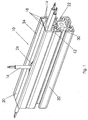
- eine perspektivische Darstellung eines ersten Ausführungsbeispieles eines Leitungsaufnahmeelements hier in Verbindung mit einem Profilstab;
- Fig.2
- den Querschnitt des Leitungsaufnahmeelements gemäß
Fig.1 ; - Fig.3
- den Querschnitt der Anordnung gemäß
Fig.1 ; und - Fig.4
- ein weiteres Ausführungsbeispiel eines Leitungsaufnahmeelementes mit unterschiedlichen Materialien.
- Anhand der
Figuren 1 bis 4 werden nunmehr zwei Ausführungsbeispiele eines Leitungsaufnahmeelements 10 näher beschrieben. Dabei bedeuten gleiche Bezugsziffern gleiche Merkmale, soweit nichts anderes ausgesägt ist. - Das erste Ausführungsbeispiel, das in den
Figuren 1 bis 3 dargestellt ist, weist auch wie das Ausführungsbeispiel gem.Figur 4 eine Basis 12 auf. Von dieser Basis 12 erstrecken sich bei diesem Ausführungsbeispiel in gleicher Richtung vier Seitenteile 14, die bei dieser Konstellation drei Kammern 18 zur Aufnahme jeweils einer Leitung 16 bilden. - Die drei Kammern 18 werden auf der der Basis 12 entgegen gesetzten Seite mit einer sogenannten Abdeckung 20 verschlossen.
- Die Besonderheit bei allen Ausführungsbeispielen besteht dann nun darin, dass diese Abdeckung 20 jeweils etwa in der Mitte der Kammerlängsachse jeweils mit einem Längsschlitz 24 versehen sind.
- Aufgrund dieses Längsschlitzes 24 sind die Bereiche der Kammern 18 mit beweglichen Lippen 26 versehen. Da das Material für die Leitungsaufnahmeelemente 10 aus mindestens einem Kunststoff besteht, sind diese Lippen 26 sowohl in Richtung der Kammer 18 als auch nach außen bewegbar.
- Obwohl zur Befestigung des Leitungsaufnahmeelements 10 die Basis 12 mit einem Klebestreifen versehen werden kann, um dieses Leitungsaufnahmeelement 10 an gewünschter Position, die selbstverständlich für eine Klebeverbindung geeignet sein muss, anzubringen, ist eine andere Befestigungsmöglichkeit ausgewählt worden.
- Die gezeigten Ausführungsbeispiele weisen diese andere Verbindungsmöglichkeit auf, die in diesem Falle in Hinterschnittnuten 34 eines Profilstabes 32 eingebracht sind. Bei dieser Verbindungsart handelt es sich um einen Vorsprung 28, der aufgrund seiner Querschnittsform in Längsrichtung gesehen an den Hinterschnitt 30 der Hinterschnittnut 34 elastisch einrastend hält.
- Wie sich aus den
Figuren 1 und3 ergibt, können Leitungen 16, die in diesem Fall elektrische Leitungen sind, nach Anbringung der Leitungsaufnahmeelemente bzw. des Leitungsaufnahmeelements 10 durch Auflegen auf einen Längsschlitz 24 und festes Eindrücken durch Verdrängen der Lippen 26 in Richtung der Kammern 18 eingedrückt werden kann. - Außerdem ist in den beiden Figuren gezeigt, wie an beliebiger Stelle eine Leitung 16 wieder aus der Kammer 18 heraustritt, und zwar unter Ausbildung einer lang gestreckten Öffnung der beiden Lippen 26.
- In umgekehrter Weise kann ganz einfach das eingelegte Kabel 16 auch wieder entfernt und durch ein neues oder anderes Kabel 16 ersetzt werden. Anhand des in
Figur 2 gezeigten Querschnittes, aber auch anhand des inFigur 4 gezeigten Querschnittes des zweiten Ausführungsbeispiels, ist erkennbar, dass durch Variieren der einzelnen Wandstärken unterschiedliche Federspannungen bzw. sogenannte Federkonstanten insbesondere für die Lippen 26 durch Variieren der Wandstärken möglich ist. - Diese Variation der unterschiedlichen Federkräfte zum Zurückführen der Lippen 26 in ihre Ursprungsposition ist noch deutlicher entnehmbar aus dem Querschnitt von
Figur 4 , welche das zweite Ausführungsbeispiel zeigt. Hier bestehen die Basis 12 und die Stege 14 aus einem Kunststoffmaterial, wohingegen das Material der Abdeckung 20 und des Vorsprungs 28 nicht nur untereinander sondern auch noch zu dem Basisstegkomplex unterschiedliches Material aufweist. - Gemäß
Figur 4 sind die Stärken der äußeren Stege 14 geringer als die derjenigen der beiden inneren. - Um wieder im Querschnitt gesehen zu einem einheitlichen Dickenverhältnis zu kommen, ist bei dem zweiten Ausführungsbeispiel gemäß
Figur 4 die Abdeckung 20 auch an den Außenoberflächen der beiden äußersten Stege 14 umhüllend bis zur Basis angeordnet. Dies dient nicht nur zum Schutz der Oberfläche des Leitungsaufnahmeelements 10, sondern auch einem einheitlichen optischen Erscheinungsbild. - Was in den Figuren nicht gezeigt, aber auch noch möglich ist, besteht darin, dass das Abdeckungsmaterial zu Beginn des Steges 14 die größte Stärke aufweist, die in Richtung der Basis 12 im Verhältnis zur Stärke des Steges 14 immer geringer wird. Dies hat keine optische Ursache, sondern dient der besseren Einstellung der Federkonstante der Stege 14 im Zusammenspiel mit den Lippen 26.
- Eine weitere nicht dargestellte Möglichkeit besteht auch noch darin, die Anschlüsse oder Übergänge der Seitenteile bzw. Stege 14 mit der Abdeckung 20 entweder mit dem Stegmaterial oder mit dem Abdeckungsmaterial oder mit einer Kombination beider Materialien zu verstärken. Dadurch wird die Kraft auf die Lippen 24 an der Stelle, an der eine Leitung 16 lange herausgetreten war, deutlich erhöht. Dabei ist zu bemerken, dass die Verstärkungen sich in die Kammern 18 hineinerstrecken, um das optische Erscheinungsbild nicht zu stören. Es kann aber auch oberhalb der Stege und außerhalb auf der Abdeckung 20 diese Verstärkung angeordnet werden.
- Des weiteren ist es selbstverständlich möglich, weniger, aber auch mehr als die dargestellten Kammern 18 für das Leitungsaufnahmeelement vorzusehen. Die Anzahl der Vorsprünge 28 ist nicht abhängig von der Anzahl der Kammern 18. Bei großen Leitungsaufnahmeelementen 10 können mehrere Vorsprünge 28 sinnvoll sein.
-
- 10
- Leitungsaufnahmeelement
- 12
- Basis
- 14
- Seitenteil, Steg
- 16
- Leitung
- 18
- Kammer
- 20
- Abdeckung
- 22
- Befestigungseinrichtung
- 24
- Längsschlitz
- 26
- Lippe
- 28
- Vorsprung
- 30
- Hinterschnitt
- 32
- Profilstab
- 34
- Hinterschnittnut
Claims (11)
- Leitungsaufnahmeelement (10) mit einer Basis (12), mindestens zwei sich von der Basis (12) In glelcher Richtung erstreckenden Seitenteilen oder Stegen (14) und mit einer mindestens die freien Enden der Seitenteile oder Stege (14) schließenden Abdeckung (20) zur Ausbildung mindestens einer eine Leitung (16) aufnehmenden Kammer (18), dadurch gekennzeichnet, dass die Basis (12) auf der der Abdeckung (20) abgewandten Selte mit einer Befestigungseinrichtung (22) versehen ist, die Befestigungseinrichtung mindestens ein an der Basis (12) angeordneter und den Seitenteilen oder Stegen (14) entgegengesetzt sich erstreckender Vorsprung (28) ist, dessen Querschnittsform in Längsrichtung gesehen an mindestens einem Hinterschnitt (30) mindestens einer in einem Profilstab (32) angeordneten Hinterschnittnut (34) in Eingriff bringbar ist, alle Bestandteile aus mindestens einem Kunststoffmaterial bestehen und dass die mindestens eine Abdeckung (20) mit mindestens einem in Längsrichtung der Kammer (18) verlaufenden Längsschlitz (24) versehen ist, wodurch die Abdeckung (20) pro Kammer (18) aus zwei bewegbaren Lippen (26) besteht und dass die Basis (12), die Stege (14), die Abdeckung (20) und der Vorsprung (28) einstückig aus unterschiedlichen Materiallen bestehen, wobei das Abdeckungsmaterial und das Vorsprungsmaterial elastischer sind als das Stegmaterial.
- Leitungsaufnahmeelement (10) nach Anspruch 1, dadurch gekennzeichnet, dass eine von der mindestens einen Kammer (18) aufzunehmbare Leitung (16) eine elektrische, pneumatische oder eine Flüssigkeit führende Leitung (16) Ist.
- Leitungsaufnahmeelement (10) nach Anspruch 1, dadurch gekennzeichnet, dass der mindestens eine Vorsprung (28) an dem Leitungsaufnahmeelement (10) in Längsrichtung gesehen derart an der Basis (12) verläuft, dass das Leitungsaufnahmeelement (10) an die Außenkontur eines Profilstabes (32) angepasst Ist.
- Leitungsaufnahmeelement (10) nach Anspruch 1 oder 2, dadurch gekennzeichnet, dass mindestens zwei Vorsprünge (28) an der Basis (12) angeordnet sind.
- Leitungsaufnahmeelement (10) nach einem der Ansprüche 1 bis 4, dadurch gekennzeichnet, dass die Basis (12), die Stege (14), die Abdeckung (20) und der Vorsprung (28) einstückig aus einem elastischen Material bestehen.
- Leitungsaufnahmeelement (10) nach einem der Ansprüche 1 bis 5, dadurch gekennzeichnet, dass die Stege (14) aus dem Abdeckungsmaterial und dem Basismaterial ungemischt, aber einstückig ausgebildet sind.
- Leitungsaufnahmeelement (10) nach einem der Ansprüche 1 bis 6, dadurch gekennzeichnet, dass das Abdeckungsmaterial zu Beginn des Seitenteils oder Steges (14) die größte Stärke aufweist, die in Richtung der Basis (12) im Verhältnis zur Stärke des Steges (14) immer geringer wird.
- Leitungsaufnahmeelement (10) nach einem der Ansprüche 1 bis 7, dadurch gekennzeichnet, dass das Abdeckungsmaterial auch an den Außenflächen der beiden äußeren Stege (14) diese umhüllt.
- Leitungsaufnahmeelement (10) nach einem der Ansprüche 1 bis 8, dadurch gekennzeichnet, dass die Stärke der Stege (14) von den Stärken der Abdeckung (20) und der Basis (12) abweicht.
- Leitungsaufnahmeelement (10) nach Anspruch 8 oder 9, dadurch gekennzeichnet, dass die Stege (14) unterschiedliche Stärken aufweisen.
- Leitungsaufnahmeelement (10) nach einem der Ansprüche 8 bis 10, dadurch gekennzeichnet, dass die Anschlüsse der Übergänge von den Seitenteilen (14) oder Stegen (14) mit der Abdeckung (20) entweder mit dem Stegmaterial oder mit dem Abdeckungsmaterial oder mit einer Kombination beider Materialien verstärkt sind.
Applications Claiming Priority (2)
| Application Number | Priority Date | Filing Date | Title |
|---|---|---|---|
| DE202012002733U DE202012002733U1 (de) | 2012-03-19 | 2012-03-19 | Leitungsaufnahmeelement |
| PCT/EP2013/000736 WO2013139449A2 (de) | 2012-03-19 | 2013-03-13 | Leitungsaufnahmeelement |
Publications (2)
| Publication Number | Publication Date |
|---|---|
| EP2828943A2 EP2828943A2 (de) | 2015-01-28 |
| EP2828943B1 true EP2828943B1 (de) | 2016-08-24 |
Family
ID=46635471
Family Applications (1)
| Application Number | Title | Priority Date | Filing Date |
|---|---|---|---|
| EP13715126.2A Active EP2828943B1 (de) | 2012-03-19 | 2013-03-13 | Leitungsaufnahmeelement |
Country Status (4)
| Country | Link |
|---|---|
| US (1) | US20160043536A1 (de) |
| EP (1) | EP2828943B1 (de) |
| DE (1) | DE202012002733U1 (de) |
| WO (1) | WO2013139449A2 (de) |
Families Citing this family (4)
| Publication number | Priority date | Publication date | Assignee | Title |
|---|---|---|---|---|
| DE102015206181B4 (de) * | 2015-04-08 | 2016-10-20 | Festo Ag & Co. Kg | Leitungsverlegesystem |
| US9750156B2 (en) * | 2015-05-22 | 2017-08-29 | Drop Point Systems, Inc. | Device and system for the distribution of cabling in data center environments |
| MX2024008121A (es) * | 2023-10-27 | 2025-05-02 | Furukawa Electric Latam S A | Cable mensajero |
| EP4651324A1 (de) * | 2024-05-13 | 2025-11-19 | Alcom International GmbH | Kabelkanal |
Family Cites Families (6)
| Publication number | Priority date | Publication date | Assignee | Title |
|---|---|---|---|---|
| FR1352504A (fr) * | 1963-03-30 | 1964-02-14 | Goulottes guide-fils destinées au câblage d'installations électriques | |
| GB2130022B (en) * | 1982-09-27 | 1986-02-19 | Scott Howard Associates Limite | Cable ducting |
| US5791607A (en) * | 1997-02-13 | 1998-08-11 | Thibault; Jean Pierre | Pipe support system |
| US6476327B1 (en) * | 2000-06-01 | 2002-11-05 | Panduit Corp. | Split fiber cover and raceway fitting |
| FR2833771B1 (fr) * | 2001-12-14 | 2004-07-30 | Planet Wattohm Sa | Goulotte electrique a moyens de retenue de cables ou de conducteurs electriques |
| US7673835B2 (en) * | 2007-12-07 | 2010-03-09 | Adc Telecommunications, Inc. | Telescoping cover for cable trough system |
-
2012
- 2012-03-19 DE DE202012002733U patent/DE202012002733U1/de not_active Expired - Lifetime
-
2013
- 2013-03-13 WO PCT/EP2013/000736 patent/WO2013139449A2/de not_active Ceased
- 2013-03-13 US US14/386,348 patent/US20160043536A1/en not_active Abandoned
- 2013-03-13 EP EP13715126.2A patent/EP2828943B1/de active Active
Also Published As
| Publication number | Publication date |
|---|---|
| EP2828943A2 (de) | 2015-01-28 |
| US20160043536A1 (en) | 2016-02-11 |
| WO2013139449A2 (de) | 2013-09-26 |
| DE202012002733U1 (de) | 2012-07-05 |
| WO2013139449A3 (de) | 2013-11-14 |
Similar Documents
| Publication | Publication Date | Title |
|---|---|---|
| AT509796B1 (de) | Hohlprofil | |
| EP1833133B1 (de) | Montagevorrichtung für einen Kabelkanal und Kabelkanal | |
| DE10002075A1 (de) | Profilrahmen | |
| DE202007016585U1 (de) | Profilschienensystem | |
| EP2631414B1 (de) | Führungsschiene für Senkrechtmarkise und Senkrechtmarkise | |
| DE202012104033U1 (de) | Haltevorrichtung für eine Brüstungs- oder Geländerplatte sowie Geländer oder Brüstung mit Scheibe | |
| EP2828943A2 (de) | Leitungsaufnahmeelement | |
| DE9207859U1 (de) | Glasscheibenhalter | |
| CH653873A5 (de) | Duschtrennwand. | |
| EP2357367A1 (de) | Montagesysteme für Platten und Rohre | |
| DE19719013C2 (de) | Mit einem Wandhalter versehenes, im Querschnitt U-förmiges Halteprofil für eine Trennwand | |
| DE29518779U1 (de) | Gurtdurchführung sowie Rolladenkasten mit einer solchen Durchführung | |
| DE29718854U1 (de) | Profilrahmen, insbesondere U-Profilrahmen zur Halterung von Flächenelementen wie Glasscheiben, Kunststoffplatten o.dgl. | |
| DE3733359C2 (de) | ||
| DE202005008668U1 (de) | Leitungsführungseinrichtung für biegbare elektrische oder fluidische Leitungen | |
| EP0470603A1 (de) | Dichtungsleiste zum Abdichten von Tür- und Fensterrahmen oder dgl. Bauteilen | |
| CH435396A (de) | Leitungskanal zur Verlegung und Montage von elektrischen Leitungen, Kabeln und Anschlussapparaten an Wänden und Brüstungen, insbesondere Fensterbrüstungen | |
| AT520997B1 (de) | Montagehalter | |
| WO1996018018A1 (de) | Befestigungseinrichtung | |
| EP4174242B1 (de) | Dichtungsanordnung zur abdichtung des übergangs zwischen fassadenelementen einer elementfassade | |
| DE202007003873U1 (de) | Dichtungsprofil und Riegel-Pfosten Konstruktion | |
| EP3867463B1 (de) | Rastverbindungsanordnung und montageverfahren | |
| DE9303155U1 (de) | Duschkabine | |
| DE29511635U1 (de) | Einfaßprofil zur Klemmbefestigung von Folien und Dachbahnen am Mauerwerk | |
| DE29603258U1 (de) | Metallprofil für die Bildung von Rahmenwerken mit Eckverbindungen |
Legal Events
| Date | Code | Title | Description |
|---|---|---|---|
| PUAI | Public reference made under article 153(3) epc to a published international application that has entered the european phase |
Free format text: ORIGINAL CODE: 0009012 |
|
| 17P | Request for examination filed |
Effective date: 20141010 |
|
| AK | Designated contracting states |
Kind code of ref document: A2 Designated state(s): AL AT BE BG CH CY CZ DE DK EE ES FI FR GB GR HR HU IE IS IT LI LT LU LV MC MK MT NL NO PL PT RO RS SE SI SK SM TR |
|
| AX | Request for extension of the european patent |
Extension state: BA ME |
|
| DAX | Request for extension of the european patent (deleted) | ||
| GRAP | Despatch of communication of intention to grant a patent |
Free format text: ORIGINAL CODE: EPIDOSNIGR1 |
|
| INTG | Intention to grant announced |
Effective date: 20160301 |
|
| GRAS | Grant fee paid |
Free format text: ORIGINAL CODE: EPIDOSNIGR3 |
|
| GRAA | (expected) grant |
Free format text: ORIGINAL CODE: 0009210 |
|
| AK | Designated contracting states |
Kind code of ref document: B1 Designated state(s): AL AT BE BG CH CY CZ DE DK EE ES FI FR GB GR HR HU IE IS IT LI LT LU LV MC MK MT NL NO PL PT RO RS SE SI SK SM TR |
|
| REG | Reference to a national code |
Ref country code: GB Ref legal event code: FG4D Free format text: NOT ENGLISH |
|
| REG | Reference to a national code |
Ref country code: CH Ref legal event code: EP |
|
| REG | Reference to a national code |
Ref country code: AT Ref legal event code: REF Ref document number: 823840 Country of ref document: AT Kind code of ref document: T Effective date: 20160915 |
|
| REG | Reference to a national code |
Ref country code: IE Ref legal event code: FG4D Free format text: LANGUAGE OF EP DOCUMENT: GERMAN |
|
| REG | Reference to a national code |
Ref country code: DE Ref legal event code: R096 Ref document number: 502013004168 Country of ref document: DE |
|
| REG | Reference to a national code |
Ref country code: LT Ref legal event code: MG4D |
|
| REG | Reference to a national code |
Ref country code: NL Ref legal event code: MP Effective date: 20160824 |
|
| PG25 | Lapsed in a contracting state [announced via postgrant information from national office to epo] |
Ref country code: IT Free format text: LAPSE BECAUSE OF FAILURE TO SUBMIT A TRANSLATION OF THE DESCRIPTION OR TO PAY THE FEE WITHIN THE PRESCRIBED TIME-LIMIT Effective date: 20160824 Ref country code: RS Free format text: LAPSE BECAUSE OF FAILURE TO SUBMIT A TRANSLATION OF THE DESCRIPTION OR TO PAY THE FEE WITHIN THE PRESCRIBED TIME-LIMIT Effective date: 20160824 Ref country code: NO Free format text: LAPSE BECAUSE OF FAILURE TO SUBMIT A TRANSLATION OF THE DESCRIPTION OR TO PAY THE FEE WITHIN THE PRESCRIBED TIME-LIMIT Effective date: 20161124 Ref country code: HR Free format text: LAPSE BECAUSE OF FAILURE TO SUBMIT A TRANSLATION OF THE DESCRIPTION OR TO PAY THE FEE WITHIN THE PRESCRIBED TIME-LIMIT Effective date: 20160824 Ref country code: FI Free format text: LAPSE BECAUSE OF FAILURE TO SUBMIT A TRANSLATION OF THE DESCRIPTION OR TO PAY THE FEE WITHIN THE PRESCRIBED TIME-LIMIT Effective date: 20160824 Ref country code: NL Free format text: LAPSE BECAUSE OF FAILURE TO SUBMIT A TRANSLATION OF THE DESCRIPTION OR TO PAY THE FEE WITHIN THE PRESCRIBED TIME-LIMIT Effective date: 20160824 Ref country code: LT Free format text: LAPSE BECAUSE OF FAILURE TO SUBMIT A TRANSLATION OF THE DESCRIPTION OR TO PAY THE FEE WITHIN THE PRESCRIBED TIME-LIMIT Effective date: 20160824 |
|
| PG25 | Lapsed in a contracting state [announced via postgrant information from national office to epo] |
Ref country code: SE Free format text: LAPSE BECAUSE OF FAILURE TO SUBMIT A TRANSLATION OF THE DESCRIPTION OR TO PAY THE FEE WITHIN THE PRESCRIBED TIME-LIMIT Effective date: 20160824 Ref country code: LV Free format text: LAPSE BECAUSE OF FAILURE TO SUBMIT A TRANSLATION OF THE DESCRIPTION OR TO PAY THE FEE WITHIN THE PRESCRIBED TIME-LIMIT Effective date: 20160824 Ref country code: ES Free format text: LAPSE BECAUSE OF FAILURE TO SUBMIT A TRANSLATION OF THE DESCRIPTION OR TO PAY THE FEE WITHIN THE PRESCRIBED TIME-LIMIT Effective date: 20160824 Ref country code: GR Free format text: LAPSE BECAUSE OF FAILURE TO SUBMIT A TRANSLATION OF THE DESCRIPTION OR TO PAY THE FEE WITHIN THE PRESCRIBED TIME-LIMIT Effective date: 20161125 Ref country code: PT Free format text: LAPSE BECAUSE OF FAILURE TO SUBMIT A TRANSLATION OF THE DESCRIPTION OR TO PAY THE FEE WITHIN THE PRESCRIBED TIME-LIMIT Effective date: 20161226 |
|
| REG | Reference to a national code |
Ref country code: FR Ref legal event code: PLFP Year of fee payment: 5 |
|
| PG25 | Lapsed in a contracting state [announced via postgrant information from national office to epo] |
Ref country code: EE Free format text: LAPSE BECAUSE OF FAILURE TO SUBMIT A TRANSLATION OF THE DESCRIPTION OR TO PAY THE FEE WITHIN THE PRESCRIBED TIME-LIMIT Effective date: 20160824 Ref country code: RO Free format text: LAPSE BECAUSE OF FAILURE TO SUBMIT A TRANSLATION OF THE DESCRIPTION OR TO PAY THE FEE WITHIN THE PRESCRIBED TIME-LIMIT Effective date: 20160824 |
|
| REG | Reference to a national code |
Ref country code: DE Ref legal event code: R097 Ref document number: 502013004168 Country of ref document: DE |
|
| PG25 | Lapsed in a contracting state [announced via postgrant information from national office to epo] |
Ref country code: CZ Free format text: LAPSE BECAUSE OF FAILURE TO SUBMIT A TRANSLATION OF THE DESCRIPTION OR TO PAY THE FEE WITHIN THE PRESCRIBED TIME-LIMIT Effective date: 20160824 Ref country code: PL Free format text: LAPSE BECAUSE OF FAILURE TO SUBMIT A TRANSLATION OF THE DESCRIPTION OR TO PAY THE FEE WITHIN THE PRESCRIBED TIME-LIMIT Effective date: 20160824 Ref country code: SK Free format text: LAPSE BECAUSE OF FAILURE TO SUBMIT A TRANSLATION OF THE DESCRIPTION OR TO PAY THE FEE WITHIN THE PRESCRIBED TIME-LIMIT Effective date: 20160824 Ref country code: BG Free format text: LAPSE BECAUSE OF FAILURE TO SUBMIT A TRANSLATION OF THE DESCRIPTION OR TO PAY THE FEE WITHIN THE PRESCRIBED TIME-LIMIT Effective date: 20161124 Ref country code: DK Free format text: LAPSE BECAUSE OF FAILURE TO SUBMIT A TRANSLATION OF THE DESCRIPTION OR TO PAY THE FEE WITHIN THE PRESCRIBED TIME-LIMIT Effective date: 20160824 Ref country code: SM Free format text: LAPSE BECAUSE OF FAILURE TO SUBMIT A TRANSLATION OF THE DESCRIPTION OR TO PAY THE FEE WITHIN THE PRESCRIBED TIME-LIMIT Effective date: 20160824 |
|
| PLBE | No opposition filed within time limit |
Free format text: ORIGINAL CODE: 0009261 |
|
| STAA | Information on the status of an ep patent application or granted ep patent |
Free format text: STATUS: NO OPPOSITION FILED WITHIN TIME LIMIT |
|
| 26N | No opposition filed |
Effective date: 20170526 |
|
| PG25 | Lapsed in a contracting state [announced via postgrant information from national office to epo] |
Ref country code: SI Free format text: LAPSE BECAUSE OF FAILURE TO SUBMIT A TRANSLATION OF THE DESCRIPTION OR TO PAY THE FEE WITHIN THE PRESCRIBED TIME-LIMIT Effective date: 20160824 |
|
| REG | Reference to a national code |
Ref country code: CH Ref legal event code: PL |
|
| PG25 | Lapsed in a contracting state [announced via postgrant information from national office to epo] |
Ref country code: MC Free format text: LAPSE BECAUSE OF FAILURE TO SUBMIT A TRANSLATION OF THE DESCRIPTION OR TO PAY THE FEE WITHIN THE PRESCRIBED TIME-LIMIT Effective date: 20160824 |
|
| REG | Reference to a national code |
Ref country code: IE Ref legal event code: MM4A |
|
| PG25 | Lapsed in a contracting state [announced via postgrant information from national office to epo] |
Ref country code: LU Free format text: LAPSE BECAUSE OF NON-PAYMENT OF DUE FEES Effective date: 20170313 |
|
| PG25 | Lapsed in a contracting state [announced via postgrant information from national office to epo] |
Ref country code: LI Free format text: LAPSE BECAUSE OF NON-PAYMENT OF DUE FEES Effective date: 20170331 Ref country code: CH Free format text: LAPSE BECAUSE OF NON-PAYMENT OF DUE FEES Effective date: 20170331 Ref country code: IE Free format text: LAPSE BECAUSE OF NON-PAYMENT OF DUE FEES Effective date: 20170313 |
|
| REG | Reference to a national code |
Ref country code: BE Ref legal event code: MM Effective date: 20170331 |
|
| REG | Reference to a national code |
Ref country code: FR Ref legal event code: PLFP Year of fee payment: 6 |
|
| PG25 | Lapsed in a contracting state [announced via postgrant information from national office to epo] |
Ref country code: BE Free format text: LAPSE BECAUSE OF NON-PAYMENT OF DUE FEES Effective date: 20170331 |
|
| PG25 | Lapsed in a contracting state [announced via postgrant information from national office to epo] |
Ref country code: MT Free format text: LAPSE BECAUSE OF FAILURE TO SUBMIT A TRANSLATION OF THE DESCRIPTION OR TO PAY THE FEE WITHIN THE PRESCRIBED TIME-LIMIT Effective date: 20160824 |
|
| PG25 | Lapsed in a contracting state [announced via postgrant information from national office to epo] |
Ref country code: AL Free format text: LAPSE BECAUSE OF FAILURE TO SUBMIT A TRANSLATION OF THE DESCRIPTION OR TO PAY THE FEE WITHIN THE PRESCRIBED TIME-LIMIT Effective date: 20160824 |
|
| REG | Reference to a national code |
Ref country code: DE Ref legal event code: R082 Ref document number: 502013004168 Country of ref document: DE Ref country code: DE Ref legal event code: R082 Ref document number: 502013004168 Country of ref document: DE Representative=s name: BRP RENAUD UND PARTNER MBB RECHTSANWAELTE PATE, DE |
|
| REG | Reference to a national code |
Ref country code: AT Ref legal event code: MM01 Ref document number: 823840 Country of ref document: AT Kind code of ref document: T Effective date: 20180313 |
|
| PG25 | Lapsed in a contracting state [announced via postgrant information from national office to epo] |
Ref country code: HU Free format text: LAPSE BECAUSE OF FAILURE TO SUBMIT A TRANSLATION OF THE DESCRIPTION OR TO PAY THE FEE WITHIN THE PRESCRIBED TIME-LIMIT; INVALID AB INITIO Effective date: 20130313 |
|
| PG25 | Lapsed in a contracting state [announced via postgrant information from national office to epo] |
Ref country code: CY Free format text: LAPSE BECAUSE OF FAILURE TO SUBMIT A TRANSLATION OF THE DESCRIPTION OR TO PAY THE FEE WITHIN THE PRESCRIBED TIME-LIMIT Effective date: 20160824 Ref country code: AT Free format text: LAPSE BECAUSE OF NON-PAYMENT OF DUE FEES Effective date: 20180313 |
|
| PG25 | Lapsed in a contracting state [announced via postgrant information from national office to epo] |
Ref country code: MK Free format text: LAPSE BECAUSE OF FAILURE TO SUBMIT A TRANSLATION OF THE DESCRIPTION OR TO PAY THE FEE WITHIN THE PRESCRIBED TIME-LIMIT Effective date: 20160824 |
|
| PG25 | Lapsed in a contracting state [announced via postgrant information from national office to epo] |
Ref country code: TR Free format text: LAPSE BECAUSE OF FAILURE TO SUBMIT A TRANSLATION OF THE DESCRIPTION OR TO PAY THE FEE WITHIN THE PRESCRIBED TIME-LIMIT Effective date: 20160824 |
|
| PG25 | Lapsed in a contracting state [announced via postgrant information from national office to epo] |
Ref country code: IS Free format text: LAPSE BECAUSE OF FAILURE TO SUBMIT A TRANSLATION OF THE DESCRIPTION OR TO PAY THE FEE WITHIN THE PRESCRIBED TIME-LIMIT Effective date: 20161224 |
|
| P01 | Opt-out of the competence of the unified patent court (upc) registered |
Effective date: 20230628 |
|
| PGFP | Annual fee paid to national office [announced via postgrant information from national office to epo] |
Ref country code: GB Payment date: 20260122 Year of fee payment: 14 |
|
| PGFP | Annual fee paid to national office [announced via postgrant information from national office to epo] |
Ref country code: DE Payment date: 20260226 Year of fee payment: 14 |
|
| PGFP | Annual fee paid to national office [announced via postgrant information from national office to epo] |
Ref country code: FR Payment date: 20260323 Year of fee payment: 14 |