EP2828839B1 - Interference detection in a network of active sensors - Google Patents
Interference detection in a network of active sensors Download PDFInfo
- Publication number
- EP2828839B1 EP2828839B1 EP13722531.4A EP13722531A EP2828839B1 EP 2828839 B1 EP2828839 B1 EP 2828839B1 EP 13722531 A EP13722531 A EP 13722531A EP 2828839 B1 EP2828839 B1 EP 2828839B1
- Authority
- EP
- European Patent Office
- Prior art keywords
- timeslot
- active sensor
- control system
- sensor
- active
- Prior art date
- Legal status (The legal status is an assumption and is not a legal conclusion. Google has not performed a legal analysis and makes no representation as to the accuracy of the status listed.)
- Active
Links
- 238000001514 detection method Methods 0.000 title description 11
- 239000000523 sample Substances 0.000 claims description 66
- 238000012545 processing Methods 0.000 claims description 15
- 238000000034 method Methods 0.000 claims description 8
- 230000004044 response Effects 0.000 claims description 5
- 238000002604 ultrasonography Methods 0.000 claims description 5
- 238000005259 measurement Methods 0.000 description 7
- 238000002592 echocardiography Methods 0.000 description 4
- 230000008901 benefit Effects 0.000 description 3
- 230000005540 biological transmission Effects 0.000 description 3
- 230000003068 static effect Effects 0.000 description 3
- 238000013459 approach Methods 0.000 description 2
- 238000013461 design Methods 0.000 description 2
- 230000006870 function Effects 0.000 description 2
- 238000005286 illumination Methods 0.000 description 2
- 230000006872 improvement Effects 0.000 description 2
- 239000011159 matrix material Substances 0.000 description 2
- 230000000737 periodic effect Effects 0.000 description 2
- 230000008569 process Effects 0.000 description 2
- 238000009877 rendering Methods 0.000 description 2
- 230000003044 adaptive effect Effects 0.000 description 1
- 238000004891 communication Methods 0.000 description 1
- 230000001143 conditioned effect Effects 0.000 description 1
- 238000011217 control strategy Methods 0.000 description 1
- 238000005265 energy consumption Methods 0.000 description 1
- 238000012986 modification Methods 0.000 description 1
- 230000004048 modification Effects 0.000 description 1
- 230000001360 synchronised effect Effects 0.000 description 1
Images

Classifications
-
- G—PHYSICS
- G08—SIGNALLING
- G08C—TRANSMISSION SYSTEMS FOR MEASURED VALUES, CONTROL OR SIMILAR SIGNALS
- G08C15/00—Arrangements characterised by the use of multiplexing for the transmission of a plurality of signals over a common path
- G08C15/06—Arrangements characterised by the use of multiplexing for the transmission of a plurality of signals over a common path successively, i.e. using time division
-
- G—PHYSICS
- G08—SIGNALLING
- G08B—SIGNALLING OR CALLING SYSTEMS; ORDER TELEGRAPHS; ALARM SYSTEMS
- G08B5/00—Visible signalling systems, e.g. personal calling systems, remote indication of seats occupied
- G08B5/22—Visible signalling systems, e.g. personal calling systems, remote indication of seats occupied using electric transmission; using electromagnetic transmission
- G08B5/36—Visible signalling systems, e.g. personal calling systems, remote indication of seats occupied using electric transmission; using electromagnetic transmission using visible light sources
-
- G—PHYSICS
- G08—SIGNALLING
- G08C—TRANSMISSION SYSTEMS FOR MEASURED VALUES, CONTROL OR SIMILAR SIGNALS
- G08C23/00—Non-electrical signal transmission systems, e.g. optical systems
- G08C23/02—Non-electrical signal transmission systems, e.g. optical systems using infrasonic, sonic or ultrasonic waves
-
- H—ELECTRICITY
- H04—ELECTRIC COMMUNICATION TECHNIQUE
- H04W—WIRELESS COMMUNICATION NETWORKS
- H04W84/00—Network topologies
- H04W84/18—Self-organising networks, e.g. ad-hoc networks or sensor networks
Definitions
- the present invention generally relates to the field of control systems, and in particular to a control system comprising a first active sensor and a second active sensor and methods corresponding thereto.
- Office lighting constitutes almost 30% of the electrical consumption in buildings.
- LED light-emitting-diode
- they are becoming viable alternatives for fluorescent lamps, further offering the advantage of color control.
- lighting control strategies based on occupant presence information are very effective in reducing energy consumption. For example, in unoccupied areas the illumination may be dimmed or extinguished.
- the design of green buildings may benefit from presence-adaptive lighting control systems.
- active sensors such as ultrasound based sensors
- An ultrasonic array sensor has been described in WO 2011/151796 A1 for reliable presence sensing that, when interfaced with a lighting control system, provides reliable illumination rendering.
- cross-interference across active sensors is a problem in indoor as well as outdoor sensing applications.
- Cross-interference across active sensors generally depends on the dimensions of the monitored space and presence/absence of objects therein. For instance, when an object is moved (or added/removed) the cross-interference pattern across sensors tends to vary. This affects proper operation of the presence sensing systems.
- the presence sensing system When presence sensing systems are deployed, it may be necessary to avoid potential cross-interference across active transmissions.
- the presence sensing system as a whole needs to function properly, with each individual presence sensor being able to determine presence-related information in its coverage area. It is an object of the present invention to overcome these problems, and to provide a control system comprising a number of active sensors that are arranged to detect, mitigate and use the cross-interference to improve the system performance.
- a control system comprising a first active sensor comprising a transmitter arranged to in a first timeslot transmit a first probe signal comprising two non-zero pulses transmitted in respective parts of the first timeslot; and a second active sensor comprising a receiving sensor array arranged to receive the first probe signal; and a processing unit arranged to, in a second timeslot, determine a difference between signals received in a first part of the second timeslot and signals received in a second part of the second timeslot, the processing unit thereby being arranged to detect cross-interference between the active sensors, cross-interference being detected if the power in the difference signal has an absolute value that is larger than a predefined threshold value.
- the first aspect allows for detection of cross-interference, particularly in varying environments.
- the cross-interference may vary in time, inter alia due to addition, removal, or moving of objects placed between the active sensors of the control system.
- this may enable improvement in performance of presence detection.
- the second active sensor is able to detect interference without needing to transmit a probe signal of its own.
- the second active sensor further comprises a transmitter arranged to in the second timeslot transmit a second probe signal comprising two non-zero pulses transmitted in respective parts of the second timeslot, wherein the receiving sensor array further is arranged to receive an echo of the second probe signal, and wherein the processing unit, by determining the difference, is arranged to cancel the two non-zero pulses of the second probe signal.
- the second active sensor further comprises a transmitter arranged to in the second timeslot and in response to the receiving sensor array receiving the first probe signal transmit an announcing signal pertaining to the second active sensor being added to the control system, and wherein the first active sensor further comprises a receiving sensor array arranged to receive the announcing signal.
- a new active sensor (in the claim language: the second active sensor) may thereby be added to an existing control system already comprising one or more active sensors (in the claim language: the first active sensor).
- the detected cross-interference may thereby facilitate the addition of a new active sensor into the control system.
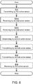
- the objective is achieved by a method of detecting interference in a control system, comprising transmitting, by a first active sensor, in a first timeslot a first probe signal comprising two non-zero pulses transmitted in respective parts of the first timeslot; receiving, by a second active sensor, the first probe signal; and determining, by the second active sensor, in a second timeslot a difference between signals received in a first part of the second timeslot and signals received in a second part of the second timeslot, the second active sensor thereby being arranged to detect cross-interference between the active sensors, cross-interference being detected if the power in the difference signal has an absolute value that is larger than a predefined threshold value.
- Embodiments of the present invention may be applied to improvements of localized lighting rendering in a location with a fixed sensor infrastructure.
- the next tasking sensor for the next time step is scheduled according to predicted tracking accuracy which is derived from the trace of the covariance matrix of the state estimation. It is therefore conditioned that each sensor knows the measurement characteristic of the other sensors (such as their locations, orientations and measurement functions).
- the current sensor can calculate the predicted covariance matrix for any other sensor without the real measurement is taken using that sensor. The sensor with the best tracking accuracy is selected as the next tasking sensor. Then the current sensor shall forward its own measurement time and estimation result to the selected sensor.
- Fig. 1 schematically illustrates a control system 1 according to the present invention.
- the control system 1 is according to the schematic example of Fig. 1 placed in a room, the inner walls of which are denoted by reference numeral 15.
- the room is a room of a building.
- the control system 1 comprises a number of active sensors 2a, 2b, 2c, 2d, one of which herein is denoted as a first active sensor, for example sensor 2a, another of which herein is denoted a second active sensor, for example sensor 2b, another of which herein is denoted a third active sensor, for example sensor 2c, and another of which herein is denoted a fourth active sensor, for example sensor 2d.
- control system 1 comprises at least two active sensors but may in general comprise a plurality of active sensors.
- An object 7 symbolizes a static object present in the room. For example, when the room is an office the object 7 may be a desk.
- the control system 1 may further comprise at least one light source (not shown), other sensors, etc.
- Fig. 2 illustrates an active sensor 2a, 2b, 2c, 2d according to embodiments of the present invention.
- the active sensor 2a, 2b, 2c, 2d may comprise a transmitter 3, a receiver 4, and a processing unit 5.
- the receiver 4 is preferably a receiver sensor array and thus preferably comprises one or more receiver elements in an array.
- the active sensor 2a, 2b, 2c, 2d may further comprise or be operatively coupled to a light source 6.
- the active sensor 2a, 2b, 2c, 2d and one or more light sources 6 are part of a luminaire.
- the active sensors 2a, 2b, 2c, 2d of the control system 1 may thereby provide presence detection information to a distributed lighting system which may include the one or more light sources 6.
- each active sensor 2a, 2b, 2c, 2d may be arranged to transmit a waveform (schematically illustrated by arrows 11, 12a, 13, 14) over an area defined by the directivity of the transmitter 3.
- a waveform (schematically illustrated by arrows 11, 12a, 13, 14) over an area defined by the directivity of the transmitter 3.
- Fig. 1 only signals received by the active sensor 2b are illustrated.
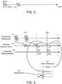
- Fig. 3 illustrates one example of a transmitted waveform in the form of a probe signal.
- the parameter T defines a length over which the waveform is non-zero in each pulse repetition interval (PRI) and is chosen as per the spatial resolution required.
- PRI pulse repetition interval
- the PRI is generally chosen to accommodate the largest expected range in time before an echo (such as the echo 12b) of the transmitted probe signal (such as the probe signal 12a) is expected to be received by the receiver 4.
- each active sensor currently deployed in the control system 1 is assigned to a timeslot wherein it is arranged to transmit its probe signal. Such timeslots will be further disclosed below with references to Figs. 4-7 .
- the probe signals 11, 12a, 13, 14 are received by the receiver 4 of the active sensor 2a, 2b, 2c, 2d. At the receiver side, the received signals are then processed, for example in order to derive presence-related sensing information.
- Each active sensor currently deployed in the control system 1 is assigned to a timeslot wherein it is arranged to receive the echo of its probe signal.
- the assigned timeslot for transmitting its own probe signal and the assigned timeslot for receiving the echo thereof is one and the same timeslot.
- each active sensor currently deployed in the control system 1 is assigned to a unique timeslot.
- the timeslots are adjacent and nonoverlapping.
- the timeslots may be randomly reassigned for several instances.
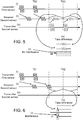
- the active sensor 2a (the first active sensor) and the active sensor 2b (the second active sensor) are assigned timeslots TS1 and TS2, respectively.
- each active sensor is arranged to transmit two consecutive pulses and to listen to the echoes thereof.
- the transmitter 3 of the first active sensor 2a is, in a step S02 as at (i) in Fig. 4 , arranged to in a first timeslot TS1 transmit a first probe signal 11, as represented by the waveform illustrated in Fig.
- the first probe signal 11 comprises two non-zero pulses transmitted in respective parts of the first timeslot TS1.
- the first probe signal 11 is at (ii) in Fig. 4 received by the receiver 4 of the second active sensor 2b, step S04a.
- the transmitter 3 of the second active sensor 2b may, in a step S08 as at (iii) in Fig. 4 , be arranged to in a second timeslot TS2 transmit a second probe signal 12a, as represented by the waveform illustrated in Fig. 3 , over an area defined by the directivity (i.e. field-of-view) of the transmitter 3 of the second active sensor 2b.
- the second probe signal 12a comprises two non-zero pulses transmitted in respective parts of the second timeslot TS2.
- An echo 12b of the second probe signal 12a is at (ii) in Fig. 4 received by the receiver 4 of the second active sensor 2b, step S04b.
- the processing unit 5 of the second active sensor 2b in a step S06 as at (iv) in Fig. 4 , in the second timeslot TS2 determines a difference between signals received in a first part of the second timeslot and signals received in a second part of the second timeslot TS2.
- a difference signal is thereby obtained by taking the difference of echo signals corresponding to two PRIs. Subtraction may involve time shift and/or scaling of the signals in the two PRIs.
- the first part corresponds to the first half of the second timeslot TS2 and the second part corresponds to the second half of the second timeslot TS2.
- a static object results in a corresponding (almost) zero difference signal component at the related time-of-flight, whereas a moving object results in a non-zero signal component at the related time-of-flight.
- the power in the difference signal at different time-of-flight windows can thus be used to, by means of the second probe signal 12a and its echo 12b, detect human presence in the room 15. Echoes from static objects (e.g. the object 7) generally result in the same contribution in received signals and so are cancelled out.
- the processing unit 5 is thereby arranged to detect interference. Interference may be detected when the difference has an absolute value that is larger than a predetermined threshold.
- the processing unit 4 may also perform correlation in order to detect interference.
- the waveform of the first probe signal 11 may then preferably be uncorrelated to the waveform of the second probe signal 12a (and the echo 12b thereof).
- the second active sensor 2b and the third active sensor 2c are assigned timeslots TS3 and TS2, respectively.
- no object is present between the second active sensor 2b and the third active sensor 2c, so no additional interference originating from the third active sensor 2c to the second active sensor 2b is received, as illustrated in Fig. 5 .
- the third active sensor 2c in timeslot TS2 transmits a third probe signal 13.
- the second active sensor 2b receives the third probe signal 13.
- in timeslot TS3 the second active sensor 2b transmits a second probe signal 12a.
- the second active sensor 2b receives an echo 12b of the second probe signal 12a.
- the processing unit 4 is thereby arranged to cancel the two non-zero pulses of the second probe signal by subtracting the non-zero pulse received in the first part of in timeslot TS3 from the non-zero pulse received in the second part of in timeslot TS3 (or vice versa).
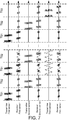
- one or more of the active sensors may skip from time to time the transmission of a probe signal in its assigned slot, say timeslot TS2, as shown in Fig. 6 .
- the first active sensor 2a transmits a first probe signal 11.
- the second active sensor 2b receives (parts of) the first probe signal 11.
- in timeslot TS2 the second active sensor 2b does not transmits any probe signal (i.e., the second active sensor 2b is silent in its allocated timeslot TS2).
- any echo received during timeslot TS2 will thus have originated from a neighbor active sensor, i.e., the first active sensor 2a, and thus be determined by the processing unit 4 of the second active sensor 2b at (v) as interference.
- This interference knowledge may be used in a similar way as according to the previous embodiment to improve the control system 1.
- the active sensors 2a, 2b may thus discard those parts (ranges) of timeslot TS2 where interference has been detected, set a higher threshold for echo detection (i.e. increase the predetermined threshold) or be re-assigned (thereby reallocated) to timeslots with minimum interference from others active sensors.
- the control system 1 comprises the active sensors 2a and 2b (i.e., the first and second active sensors).
- a new active sensor say, the active sensor 2c (the third active sensor)
- the new active sensor 2c detects that all the timeslot are occupied
- it may transmit an announcement signal, for example a probe signal in a frequency different from the above disclosed first and second probe signals or a strong continuous sinusoidal signal for a few cycles, which may be one or more whole timeslots, in order to signal the active sensors 2a, 2b currently in the control system 1 that an additional timeslot should be inserted and thus also that the currently assigned timeslots should be reassigned.
- the first active sensor 2a is assigned timeslot TS1 and the second active sensor 2b is assigned timeslot TS2.
- the first active sensor 2a transmits its first probe signal 11 which is received by the second active sensor 2b and the new active sensor 2c and the echo of the first probe signal is received by the first active sensor 2a.
- the second active sensor 2b transmits its second probe signal 12a which is received by the first active sensor 2a and the new active sensor 2c and the echo 12b of the second probe signal is received by the second active sensor 2b.
- the new active sensor 2c in a step S10, transmits an announcement signal pertaining to the third active sensor 2c being added to the control system 1.
- in timeslot TS1 (and/or in addition to receiving the second probe signal of the second active sensor 2b also the announcement signal of the new active sensor 2c is received in timeslot TS2).
- the active sensors 2a, 2b currently in the control system 1 would thus detect the announcement signal as interference in all the timeslots (as disclosed above with references to Figs. 4-6 ) and would hence realize that a new active sensor 2c is in the process of being added to the control system 1 and thus that a new timeslot is required.
- a new timeslot TS3 is then added and the timeslots TS1, TS2, TS3 are re-allocated to the active sensor 2a, 2b, 2c in the control system 1.
- the first active sensor 2a is assigned timeslot TS1
- the second active sensor 2b is assigned timeslot TS2
- the newly added third active sensor 2c is assigned timeslot TS3.
- the third active sensor 2c transmits its probe signal which is received by the first active sensor 2a and the second active sensor 2b and the echo of the probe signal is received by the third active sensor 2c.
- Other assignments of the timeslots TS1, TS2, TS3 are equally possible.
- the above probe signals and announcement signal have a carrier frequency of approximately 30-50 kHz, preferably 25-45 kHz, even more preferably 40 kHz and a bandwidth of approximately 1-5 kHz, preferably 1-3 kHz, even more preferably 2 kHz.
- a commercial off-the-shelf transmitter with a carrier frequency of 40 kHz having a typical bandwidth of 2 kHz may be used.
- the active sensors which may be fixed-infrastructure sensors, provide presence detection information to a distributed lighting system.
- the active sensors communicate by transmitting probe signals.
- the communication of probe signals may result in cross-interference which may vary in time. Cross-interference is detected, and can later be avoided, by determining a difference between signals received in a first part of a timeslot and signals received in a second part of the timeslot.
- probe signals comprising two non-zero pulses are transmitted in respective parts of the timeslot.
- the number of non-zero pulses in each probe signal may not be limited to two.
- the number of non-zero pulses in each probe signal corresponds to the number of parts that each timeslot is divided into for purposes of detecting interference.
- each timeslot is divided into an even number of parts, and thus preferably the number of non-zero pulses in each probe signal is then also even.
Landscapes
- Physics & Mathematics (AREA)
- General Physics & Mathematics (AREA)
- Electromagnetism (AREA)
- Measurement Of Velocity Or Position Using Acoustic Or Ultrasonic Waves (AREA)
- Geophysics And Detection Of Objects (AREA)
Applications Claiming Priority (2)
| Application Number | Priority Date | Filing Date | Title |
|---|---|---|---|
| US201261613135P | 2012-03-20 | 2012-03-20 | |
| PCT/IB2013/051971 WO2013140303A1 (en) | 2012-03-20 | 2013-03-13 | Interference detection in a network of active sensors |
Publications (2)
| Publication Number | Publication Date |
|---|---|
| EP2828839A1 EP2828839A1 (en) | 2015-01-28 |
| EP2828839B1 true EP2828839B1 (en) | 2017-10-25 |
Family
ID=48430863
Family Applications (1)
| Application Number | Title | Priority Date | Filing Date |
|---|---|---|---|
| EP13722531.4A Active EP2828839B1 (en) | 2012-03-20 | 2013-03-13 | Interference detection in a network of active sensors |
Country Status (6)
| Country | Link |
|---|---|
| US (1) | US9245426B2 (ja) |
| EP (1) | EP2828839B1 (ja) |
| JP (1) | JP6198809B2 (ja) |
| CN (1) | CN104205182B (ja) |
| RU (1) | RU2617324C2 (ja) |
| WO (1) | WO2013140303A1 (ja) |
Families Citing this family (15)
| Publication number | Priority date | Publication date | Assignee | Title |
|---|---|---|---|---|
| EP2837270B1 (en) * | 2012-04-10 | 2020-06-17 | Signify Holding B.V. | Fault detection, localization and performance monitoring of photosensors for lighting controls |
| EP2850453B1 (en) * | 2012-05-15 | 2019-09-25 | Signify Holding B.V. | Control of lighting devices |
| US10361585B2 (en) | 2014-01-27 | 2019-07-23 | Ivani, LLC | Systems and methods to allow for a smart device |
| US10121470B2 (en) * | 2014-06-11 | 2018-11-06 | Honeywell International Inc. | Computer-generated speech device for site survey and maintenance |
| US9474042B1 (en) | 2015-09-16 | 2016-10-18 | Ivani, LLC | Detecting location within a network |
| US10325641B2 (en) | 2017-08-10 | 2019-06-18 | Ivani, LLC | Detecting location within a network |
| US11533584B2 (en) | 2015-09-16 | 2022-12-20 | Ivani, LLC | Blockchain systems and methods for confirming presence |
| US10382893B1 (en) | 2015-09-16 | 2019-08-13 | Ivani, LLC | Building system control utilizing building occupancy |
| US10321270B2 (en) | 2015-09-16 | 2019-06-11 | Ivani, LLC | Reverse-beacon indoor positioning system using existing detection fields |
| US10455357B2 (en) | 2015-09-16 | 2019-10-22 | Ivani, LLC | Detecting location within a network |
| US11350238B2 (en) | 2015-09-16 | 2022-05-31 | Ivani, LLC | Systems and methods for detecting the presence of a user at a computer |
| US10665284B2 (en) | 2015-09-16 | 2020-05-26 | Ivani, LLC | Detecting location within a network |
| CN107623551B (zh) * | 2016-07-13 | 2021-08-06 | 意法半导体国际有限公司 | 用于检测邻近有源近场通信设备的方法及电路装置 |
| CN107015241B (zh) * | 2017-04-14 | 2020-07-17 | 北京佳讯飞鸿电气股份有限公司 | 一种多雷达探测方法及装置 |
| CN110531428B (zh) * | 2019-07-08 | 2021-09-28 | 山东省地质矿产勘查开发局八〇一水文地质工程地质大队 | 一种地下水探测监控系统及探测监控方法 |
Citations (2)
| Publication number | Priority date | Publication date | Assignee | Title |
|---|---|---|---|---|
| US20040066323A1 (en) | 2000-12-01 | 2004-04-08 | Karl-Heinz Richter | Pulse radar method, pulse radar sensor and corresponding system |
| US20090203320A1 (en) | 2008-02-07 | 2009-08-13 | Qualcomm Incorporated | Asynchronous interference management based on timeslot overlap |
Family Cites Families (21)
| Publication number | Priority date | Publication date | Assignee | Title |
|---|---|---|---|---|
| US5194847A (en) * | 1991-07-29 | 1993-03-16 | Texas A & M University System | Apparatus and method for fiber optic intrusion sensing |
| JP3302830B2 (ja) * | 1994-05-19 | 2002-07-15 | 本田技研工業株式会社 | 時分割多重型マルチチャネル・レーダ装置 |
| GB9805860D0 (en) * | 1998-03-20 | 1998-05-13 | Philips Electronics Nv | Timing control of transmission time slot |
| RU2145735C1 (ru) * | 1999-02-16 | 2000-02-20 | Военная академия Ракетных войск стратегического назначения им.Петра Великого | Способ контроля и оценки технического состояния многопараметрического объекта диагностики по данным измерительной информации |
| US6414955B1 (en) | 1999-03-23 | 2002-07-02 | Innovative Technology Licensing, Llc | Distributed topology learning method and apparatus for wireless networks |
| DE19941846C1 (de) * | 1999-09-02 | 2000-11-23 | Siemens Ag | Verfahren zur Messung von Interzell-Interferenz in einem Frequenzkanal |
| JP2001177464A (ja) * | 1999-12-20 | 2001-06-29 | Nec Corp | 無線中継装置 |
| IL134026A (en) * | 2000-01-13 | 2005-11-20 | Visonic Ltd | Circuitry for signal measurement |
| US6933845B2 (en) * | 2003-04-08 | 2005-08-23 | Lockheed Martin Corporation | Photon intrusion detector |
| US7286624B2 (en) * | 2003-07-03 | 2007-10-23 | Navcom Technology Inc. | Two-way RF ranging system and method for local positioning |
| JP2006317238A (ja) * | 2005-05-11 | 2006-11-24 | Keyence Corp | 多光軸光電式安全装置 |
| US8299900B2 (en) * | 2006-09-27 | 2012-10-30 | Alcatel Lucent | Anonymous tracking using a set of wireless devices |
| GB2445364B (en) * | 2006-12-29 | 2010-02-17 | Schlumberger Holdings | Fault-tolerant distributed fiber optic intrusion detection |
| US20080169132A1 (en) * | 2007-01-03 | 2008-07-17 | Yao Ding | Multiple styli annotation system |
| JP4921562B2 (ja) * | 2007-01-12 | 2012-04-25 | インターデイジタル テクノロジー コーポレーション | 無線基地局における干渉を測定する方法および装置 |
| EP2053755A1 (en) * | 2007-10-25 | 2009-04-29 | Commissariat A L'energie Atomique | Method of and apparatus for synchronisation |
| WO2011151796A1 (en) | 2010-06-03 | 2011-12-08 | Koninklijke Philips Electronics N.V. | System and method for lighting control |
| US8320403B2 (en) * | 2010-06-29 | 2012-11-27 | Excelitas Canada, Inc. | Multiplexed sensor array |
| RU2439812C1 (ru) * | 2010-10-22 | 2012-01-10 | Сергей Юрьевич Подлесный | Способ развертывания сенсорной сети и самоконфигурируемая сенсорная сеть |
| CN102033222B (zh) * | 2010-11-17 | 2013-02-13 | 吉林大学 | 大范围多目标超声跟踪定位系统和方法 |
| CN102137051B (zh) * | 2011-03-10 | 2013-03-20 | 上海交通大学 | 用于无线传感器网络的干扰检测方法及其检测装置 |
-
2013
- 2013-03-13 CN CN201380015386.7A patent/CN104205182B/zh active Active
- 2013-03-13 WO PCT/IB2013/051971 patent/WO2013140303A1/en active Application Filing
- 2013-03-13 RU RU2014142070A patent/RU2617324C2/ru active
- 2013-03-13 EP EP13722531.4A patent/EP2828839B1/en active Active
- 2013-03-13 US US14/386,596 patent/US9245426B2/en active Active
- 2013-03-13 JP JP2015501019A patent/JP6198809B2/ja not_active Expired - Fee Related
Patent Citations (2)
| Publication number | Priority date | Publication date | Assignee | Title |
|---|---|---|---|---|
| US20040066323A1 (en) | 2000-12-01 | 2004-04-08 | Karl-Heinz Richter | Pulse radar method, pulse radar sensor and corresponding system |
| US20090203320A1 (en) | 2008-02-07 | 2009-08-13 | Qualcomm Incorporated | Asynchronous interference management based on timeslot overlap |
Non-Patent Citations (6)
| Title |
|---|
| ABBASI ET AL.: "A survey on clustering algorithms for wireless sensor networks", COMPUTER COMMUNICATIONS, vol. 30, no. 14-15, 2007, pages 2826 - 2841, XP022267724 |
| HEALE ET AL.: "Fast Target Classification Using Sonar", IEEE /RSJ INTERNATIONAL CONFERENCE ON INTELLIGENT ROBOTS AND SYSTEMS, EXPANDING THE SOCIETAL ROLE OF ROBOTICS IN THE THE NEXT MILLENNIUM, vol. 3, 29 October 2001 (2001-10-29), pages 1446 - 1451, XP010573777 |
| KLEEMAN L.: "Fast and Accurate Sonar Trackers using Double Pulse Coding", IEEE /RSJ INTERNATIONAL CONFERENCE ON INTELLIGENT ROBOTS AND SYSTEMS, HUMAN AND ENVIRONMENT FRIENDLY ROBOTS WITH HIGH INTELLIGENCE AND EMOTIONAL QUOTIENTS, vol. 2, 17 October 1999 (1999-10-17), pages 1185 - 1190, XP010362470 |
| PAPER: "Review of outcome of ITU working Parties and Tasks Froups(8B, 8D, (F & 1/5)", AERONAUTICAL MOBILE COMMUNICATIONS PANEL WORKING GROUP F, 27 March 2001 (2001-03-27), XP055506472 |
| XIAO ET AL.: "Sensor Scheduling for Target Tracking in Networks of Active Sensors", ACTA AUTOMATICA SINICA, vol. 32, no. 6, November 2006 (2006-11-01), pages 922 - 928, XP055506454 |
| YE ET AL.: "An Energy-Efficient MAC Protocol for Wireless Sensor Networks", IEEE COMPUTER AND COMMUNICATIONS SOCIETIES, 2002, pages 1567 - 1576, XP055506478 |
Also Published As
| Publication number | Publication date |
|---|---|
| JP6198809B2 (ja) | 2017-09-20 |
| US20150048954A1 (en) | 2015-02-19 |
| CN104205182B (zh) | 2018-03-09 |
| RU2617324C2 (ru) | 2017-04-24 |
| RU2014142070A (ru) | 2016-05-10 |
| JP2015517096A (ja) | 2015-06-18 |
| CN104205182A (zh) | 2014-12-10 |
| WO2013140303A1 (en) | 2013-09-26 |
| US9245426B2 (en) | 2016-01-26 |
| EP2828839A1 (en) | 2015-01-28 |
Similar Documents
| Publication | Publication Date | Title |
|---|---|---|
| EP2828839B1 (en) | Interference detection in a network of active sensors | |
| US10444334B2 (en) | Controlling transmission of pulses from a sensor | |
| EP2936940B1 (en) | Controlling transmission of pulses from a sensor | |
| EP2891140B1 (en) | Presence detector and method of operating a presence detector | |
| EP2992740B1 (en) | Mitigating disturbance in sensing. | |
| JP2021512307A (ja) | 車両の複数のセンサを動作させるための方法および装置 | |
| Caicedo et al. | Distributed ultrasonic zoned presence sensing system | |
| KR101042365B1 (ko) | 초광대역 레이더 센서 및 중첩 영역을 가지는 초광대역 레이더 센서들 간의 동작 동기화 방법 | |
| JP4098294B2 (ja) | 位置検出システム、発信装置、サーバならびに同システムにおける無線信号の衝突回避方法 | |
| Srinivasan et al. | Self-configuring scheduling protocol for ultrasonic sensor systems | |
| EP2850453B1 (en) | Control of lighting devices | |
| JP7483147B2 (ja) | 対象物の動きを検出するための検出システム及び方法 | |
| KR101052025B1 (ko) | 주파수 변조 연속파 레이더의 분산 동기화 방법 및 이를 이용한 주파수 변조 연속파 레이더 시스템 | |
| CN116685265A (zh) | 用于检测对象的运动的检测系统和方法 |
Legal Events
| Date | Code | Title | Description |
|---|---|---|---|
| PUAI | Public reference made under article 153(3) epc to a published international application that has entered the european phase |
Free format text: ORIGINAL CODE: 0009012 |
|
| 17P | Request for examination filed |
Effective date: 20141020 |
|
| AK | Designated contracting states |
Kind code of ref document: A1 Designated state(s): AL AT BE BG CH CY CZ DE DK EE ES FI FR GB GR HR HU IE IS IT LI LT LU LV MC MK MT NL NO PL PT RO RS SE SI SK SM TR |
|
| AX | Request for extension of the european patent |
Extension state: BA ME |
|
| DAX | Request for extension of the european patent (deleted) | ||
| RAP1 | Party data changed (applicant data changed or rights of an application transferred) |
Owner name: PHILIPS LIGHTING HOLDING B.V. |
|
| STAA | Information on the status of an ep patent application or granted ep patent |
Free format text: STATUS: EXAMINATION IS IN PROGRESS |
|
| 17Q | First examination report despatched |
Effective date: 20161213 |
|
| GRAP | Despatch of communication of intention to grant a patent |
Free format text: ORIGINAL CODE: EPIDOSNIGR1 |
|
| STAA | Information on the status of an ep patent application or granted ep patent |
Free format text: STATUS: GRANT OF PATENT IS INTENDED |
|
| INTG | Intention to grant announced |
Effective date: 20170524 |
|
| RIN1 | Information on inventor provided before grant (corrected) |
Inventor name: PASVEER, WILLEM FRANKE Inventor name: CAICEDO FERNANDEZ, DAVID RICARDO Inventor name: DELNOIJ, ROGER PETER ANNA Inventor name: VANGEEL, JURGEN MARIO Inventor name: SREEDHARAN NAIR, BIJU KUMAR Inventor name: NEUTTIENS, GEERT BART Inventor name: RIETMANN, WIJNAND JOHANNES Inventor name: PANDHARIPANDE, ASHISH VIJAY Inventor name: KLEIN SWORMINK, MICHEL ALBERTUS THEODORUS Inventor name: MATOVINA, JELENA |
|
| GRAS | Grant fee paid |
Free format text: ORIGINAL CODE: EPIDOSNIGR3 |
|
| GRAA | (expected) grant |
Free format text: ORIGINAL CODE: 0009210 |
|
| STAA | Information on the status of an ep patent application or granted ep patent |
Free format text: STATUS: THE PATENT HAS BEEN GRANTED |
|
| AK | Designated contracting states |
Kind code of ref document: B1 Designated state(s): AL AT BE BG CH CY CZ DE DK EE ES FI FR GB GR HR HU IE IS IT LI LT LU LV MC MK MT NL NO PL PT RO RS SE SI SK SM TR |
|
| REG | Reference to a national code |
Ref country code: GB Ref legal event code: FG4D |
|
| REG | Reference to a national code |
Ref country code: CH Ref legal event code: EP |
|
| REG | Reference to a national code |
Ref country code: AT Ref legal event code: REF Ref document number: 940587 Country of ref document: AT Kind code of ref document: T Effective date: 20171115 |
|
| REG | Reference to a national code |
Ref country code: IE Ref legal event code: FG4D |
|
| REG | Reference to a national code |
Ref country code: DE Ref legal event code: R096 Ref document number: 602013028375 Country of ref document: DE |
|
| REG | Reference to a national code |
Ref country code: NL Ref legal event code: MP Effective date: 20171025 |
|
| REG | Reference to a national code |
Ref country code: LT Ref legal event code: MG4D |
|
| REG | Reference to a national code |
Ref country code: AT Ref legal event code: MK05 Ref document number: 940587 Country of ref document: AT Kind code of ref document: T Effective date: 20171025 |
|
| REG | Reference to a national code |
Ref country code: FR Ref legal event code: PLFP Year of fee payment: 6 |
|
| PG25 | Lapsed in a contracting state [announced via postgrant information from national office to epo] |
Ref country code: NL Free format text: LAPSE BECAUSE OF FAILURE TO SUBMIT A TRANSLATION OF THE DESCRIPTION OR TO PAY THE FEE WITHIN THE PRESCRIBED TIME-LIMIT Effective date: 20171025 |
|
| PG25 | Lapsed in a contracting state [announced via postgrant information from national office to epo] |
Ref country code: NO Free format text: LAPSE BECAUSE OF FAILURE TO SUBMIT A TRANSLATION OF THE DESCRIPTION OR TO PAY THE FEE WITHIN THE PRESCRIBED TIME-LIMIT Effective date: 20180125 Ref country code: LT Free format text: LAPSE BECAUSE OF FAILURE TO SUBMIT A TRANSLATION OF THE DESCRIPTION OR TO PAY THE FEE WITHIN THE PRESCRIBED TIME-LIMIT Effective date: 20171025 Ref country code: ES Free format text: LAPSE BECAUSE OF FAILURE TO SUBMIT A TRANSLATION OF THE DESCRIPTION OR TO PAY THE FEE WITHIN THE PRESCRIBED TIME-LIMIT Effective date: 20171025 Ref country code: FI Free format text: LAPSE BECAUSE OF FAILURE TO SUBMIT A TRANSLATION OF THE DESCRIPTION OR TO PAY THE FEE WITHIN THE PRESCRIBED TIME-LIMIT Effective date: 20171025 Ref country code: SE Free format text: LAPSE BECAUSE OF FAILURE TO SUBMIT A TRANSLATION OF THE DESCRIPTION OR TO PAY THE FEE WITHIN THE PRESCRIBED TIME-LIMIT Effective date: 20171025 |
|
| PG25 | Lapsed in a contracting state [announced via postgrant information from national office to epo] |
Ref country code: LV Free format text: LAPSE BECAUSE OF FAILURE TO SUBMIT A TRANSLATION OF THE DESCRIPTION OR TO PAY THE FEE WITHIN THE PRESCRIBED TIME-LIMIT Effective date: 20171025 Ref country code: RS Free format text: LAPSE BECAUSE OF FAILURE TO SUBMIT A TRANSLATION OF THE DESCRIPTION OR TO PAY THE FEE WITHIN THE PRESCRIBED TIME-LIMIT Effective date: 20171025 Ref country code: HR Free format text: LAPSE BECAUSE OF FAILURE TO SUBMIT A TRANSLATION OF THE DESCRIPTION OR TO PAY THE FEE WITHIN THE PRESCRIBED TIME-LIMIT Effective date: 20171025 Ref country code: GR Free format text: LAPSE BECAUSE OF FAILURE TO SUBMIT A TRANSLATION OF THE DESCRIPTION OR TO PAY THE FEE WITHIN THE PRESCRIBED TIME-LIMIT Effective date: 20180126 Ref country code: BG Free format text: LAPSE BECAUSE OF FAILURE TO SUBMIT A TRANSLATION OF THE DESCRIPTION OR TO PAY THE FEE WITHIN THE PRESCRIBED TIME-LIMIT Effective date: 20180125 Ref country code: AT Free format text: LAPSE BECAUSE OF FAILURE TO SUBMIT A TRANSLATION OF THE DESCRIPTION OR TO PAY THE FEE WITHIN THE PRESCRIBED TIME-LIMIT Effective date: 20171025 Ref country code: IS Free format text: LAPSE BECAUSE OF FAILURE TO SUBMIT A TRANSLATION OF THE DESCRIPTION OR TO PAY THE FEE WITHIN THE PRESCRIBED TIME-LIMIT Effective date: 20180225 |
|
| REG | Reference to a national code |
Ref country code: DE Ref legal event code: R026 Ref document number: 602013028375 Country of ref document: DE |
|
| PG25 | Lapsed in a contracting state [announced via postgrant information from national office to epo] |
Ref country code: CZ Free format text: LAPSE BECAUSE OF FAILURE TO SUBMIT A TRANSLATION OF THE DESCRIPTION OR TO PAY THE FEE WITHIN THE PRESCRIBED TIME-LIMIT Effective date: 20171025 Ref country code: EE Free format text: LAPSE BECAUSE OF FAILURE TO SUBMIT A TRANSLATION OF THE DESCRIPTION OR TO PAY THE FEE WITHIN THE PRESCRIBED TIME-LIMIT Effective date: 20171025 Ref country code: CY Free format text: LAPSE BECAUSE OF FAILURE TO SUBMIT A TRANSLATION OF THE DESCRIPTION OR TO PAY THE FEE WITHIN THE PRESCRIBED TIME-LIMIT Effective date: 20171025 Ref country code: DK Free format text: LAPSE BECAUSE OF FAILURE TO SUBMIT A TRANSLATION OF THE DESCRIPTION OR TO PAY THE FEE WITHIN THE PRESCRIBED TIME-LIMIT Effective date: 20171025 Ref country code: SK Free format text: LAPSE BECAUSE OF FAILURE TO SUBMIT A TRANSLATION OF THE DESCRIPTION OR TO PAY THE FEE WITHIN THE PRESCRIBED TIME-LIMIT Effective date: 20171025 |
|
| PLBI | Opposition filed |
Free format text: ORIGINAL CODE: 0009260 |
|
| PLAX | Notice of opposition and request to file observation + time limit sent |
Free format text: ORIGINAL CODE: EPIDOSNOBS2 |
|
| PG25 | Lapsed in a contracting state [announced via postgrant information from national office to epo] |
Ref country code: IT Free format text: LAPSE BECAUSE OF FAILURE TO SUBMIT A TRANSLATION OF THE DESCRIPTION OR TO PAY THE FEE WITHIN THE PRESCRIBED TIME-LIMIT Effective date: 20171025 Ref country code: SM Free format text: LAPSE BECAUSE OF FAILURE TO SUBMIT A TRANSLATION OF THE DESCRIPTION OR TO PAY THE FEE WITHIN THE PRESCRIBED TIME-LIMIT Effective date: 20171025 Ref country code: RO Free format text: LAPSE BECAUSE OF FAILURE TO SUBMIT A TRANSLATION OF THE DESCRIPTION OR TO PAY THE FEE WITHIN THE PRESCRIBED TIME-LIMIT Effective date: 20171025 Ref country code: PL Free format text: LAPSE BECAUSE OF FAILURE TO SUBMIT A TRANSLATION OF THE DESCRIPTION OR TO PAY THE FEE WITHIN THE PRESCRIBED TIME-LIMIT Effective date: 20171025 |
|
| 26 | Opposition filed |
Opponent name: MOLNIA, DAVID Effective date: 20180725 |
|
| REG | Reference to a national code |
Ref country code: CH Ref legal event code: PL |
|
| PLBB | Reply of patent proprietor to notice(s) of opposition received |
Free format text: ORIGINAL CODE: EPIDOSNOBS3 |
|
| PG25 | Lapsed in a contracting state [announced via postgrant information from national office to epo] |
Ref country code: MC Free format text: LAPSE BECAUSE OF FAILURE TO SUBMIT A TRANSLATION OF THE DESCRIPTION OR TO PAY THE FEE WITHIN THE PRESCRIBED TIME-LIMIT Effective date: 20171025 Ref country code: SI Free format text: LAPSE BECAUSE OF FAILURE TO SUBMIT A TRANSLATION OF THE DESCRIPTION OR TO PAY THE FEE WITHIN THE PRESCRIBED TIME-LIMIT Effective date: 20171025 |
|
| REG | Reference to a national code |
Ref country code: BE Ref legal event code: MM Effective date: 20180331 |
|
| RAP2 | Party data changed (patent owner data changed or rights of a patent transferred) |
Owner name: PHILIPS LIGHTING HOLDING B.V. |
|
| REG | Reference to a national code |
Ref country code: IE Ref legal event code: MM4A |
|
| PG25 | Lapsed in a contracting state [announced via postgrant information from national office to epo] |
Ref country code: LU Free format text: LAPSE BECAUSE OF NON-PAYMENT OF DUE FEES Effective date: 20180313 |
|
| PG25 | Lapsed in a contracting state [announced via postgrant information from national office to epo] |
Ref country code: IE Free format text: LAPSE BECAUSE OF NON-PAYMENT OF DUE FEES Effective date: 20180313 |
|
| PG25 | Lapsed in a contracting state [announced via postgrant information from national office to epo] |
Ref country code: CH Free format text: LAPSE BECAUSE OF NON-PAYMENT OF DUE FEES Effective date: 20180331 Ref country code: BE Free format text: LAPSE BECAUSE OF NON-PAYMENT OF DUE FEES Effective date: 20180331 Ref country code: LI Free format text: LAPSE BECAUSE OF NON-PAYMENT OF DUE FEES Effective date: 20180331 |
|
| RAP2 | Party data changed (patent owner data changed or rights of a patent transferred) |
Owner name: SIGNIFY HOLDING B.V. |
|
| PG25 | Lapsed in a contracting state [announced via postgrant information from national office to epo] |
Ref country code: MT Free format text: LAPSE BECAUSE OF NON-PAYMENT OF DUE FEES Effective date: 20180313 |
|
| PG25 | Lapsed in a contracting state [announced via postgrant information from national office to epo] |
Ref country code: TR Free format text: LAPSE BECAUSE OF FAILURE TO SUBMIT A TRANSLATION OF THE DESCRIPTION OR TO PAY THE FEE WITHIN THE PRESCRIBED TIME-LIMIT Effective date: 20171025 |
|
| PG25 | Lapsed in a contracting state [announced via postgrant information from national office to epo] |
Ref country code: HU Free format text: LAPSE BECAUSE OF FAILURE TO SUBMIT A TRANSLATION OF THE DESCRIPTION OR TO PAY THE FEE WITHIN THE PRESCRIBED TIME-LIMIT; INVALID AB INITIO Effective date: 20130313 Ref country code: PT Free format text: LAPSE BECAUSE OF FAILURE TO SUBMIT A TRANSLATION OF THE DESCRIPTION OR TO PAY THE FEE WITHIN THE PRESCRIBED TIME-LIMIT Effective date: 20171025 |
|
| PG25 | Lapsed in a contracting state [announced via postgrant information from national office to epo] |
Ref country code: MK Free format text: LAPSE BECAUSE OF NON-PAYMENT OF DUE FEES Effective date: 20171025 |
|
| PG25 | Lapsed in a contracting state [announced via postgrant information from national office to epo] |
Ref country code: AL Free format text: LAPSE BECAUSE OF FAILURE TO SUBMIT A TRANSLATION OF THE DESCRIPTION OR TO PAY THE FEE WITHIN THE PRESCRIBED TIME-LIMIT Effective date: 20171025 |
|
| REG | Reference to a national code |
Ref country code: DE Ref legal event code: R081 Ref document number: 602013028375 Country of ref document: DE Owner name: SIGNIFY HOLDING B.V., NL Free format text: FORMER OWNER: PHILIPS LIGHTING HOLDING B.V., EINDHOVEN, NL |
|
| REG | Reference to a national code |
Ref country code: DE Ref legal event code: R100 Ref document number: 602013028375 Country of ref document: DE |
|
| PLCK | Communication despatched that opposition was rejected |
Free format text: ORIGINAL CODE: EPIDOSNREJ1 |
|
| PLBN | Opposition rejected |
Free format text: ORIGINAL CODE: 0009273 |
|
| STAA | Information on the status of an ep patent application or granted ep patent |
Free format text: STATUS: OPPOSITION REJECTED |
|
| 27O | Opposition rejected |
Effective date: 20210518 |
|
| PGFP | Annual fee paid to national office [announced via postgrant information from national office to epo] |
Ref country code: FR Payment date: 20230323 Year of fee payment: 11 |
|
| P01 | Opt-out of the competence of the unified patent court (upc) registered |
Effective date: 20230421 |
|
| PGFP | Annual fee paid to national office [announced via postgrant information from national office to epo] |
Ref country code: DE Payment date: 20230530 Year of fee payment: 11 |
|
| PGFP | Annual fee paid to national office [announced via postgrant information from national office to epo] |
Ref country code: GB Payment date: 20240319 Year of fee payment: 12 |