EP2828461B1 - Roller shutter box - Google Patents
Roller shutter box Download PDFInfo
- Publication number
- EP2828461B1 EP2828461B1 EP13716421.6A EP13716421A EP2828461B1 EP 2828461 B1 EP2828461 B1 EP 2828461B1 EP 13716421 A EP13716421 A EP 13716421A EP 2828461 B1 EP2828461 B1 EP 2828461B1
- Authority
- EP
- European Patent Office
- Prior art keywords
- tract
- main body
- seat
- tongue
- coupling portion
- Prior art date
- Legal status (The legal status is an assumption and is not a legal conclusion. Google has not performed a legal analysis and makes no representation as to the accuracy of the status listed.)
- Active
Links
Images


Classifications
-
- E—FIXED CONSTRUCTIONS
- E06—DOORS, WINDOWS, SHUTTERS, OR ROLLER BLINDS IN GENERAL; LADDERS
- E06B—FIXED OR MOVABLE CLOSURES FOR OPENINGS IN BUILDINGS, VEHICLES, FENCES OR LIKE ENCLOSURES IN GENERAL, e.g. DOORS, WINDOWS, BLINDS, GATES
- E06B9/00—Screening or protective devices for wall or similar openings, with or without operating or securing mechanisms; Closures of similar construction
- E06B9/02—Shutters, movable grilles, or other safety closing devices, e.g. against burglary
- E06B9/08—Roll-type closures
- E06B9/11—Roller shutters
- E06B9/17—Parts or details of roller shutters, e.g. suspension devices, shutter boxes, wicket doors, ventilation openings
- E06B9/17007—Shutter boxes; Details or component parts thereof
- E06B9/17015—Shutter boxes; Details or component parts thereof made of at most two pieces; Front opening details
-
- F—MECHANICAL ENGINEERING; LIGHTING; HEATING; WEAPONS; BLASTING
- F16—ENGINEERING ELEMENTS AND UNITS; GENERAL MEASURES FOR PRODUCING AND MAINTAINING EFFECTIVE FUNCTIONING OF MACHINES OR INSTALLATIONS; THERMAL INSULATION IN GENERAL
- F16B—DEVICES FOR FASTENING OR SECURING CONSTRUCTIONAL ELEMENTS OR MACHINE PARTS TOGETHER, e.g. NAILS, BOLTS, CIRCLIPS, CLAMPS, CLIPS OR WEDGES; JOINTS OR JOINTING
- F16B2/00—Friction-grip releasable fastenings
- F16B2/02—Clamps, i.e. with gripping action effected by positive means other than the inherent resistance to deformation of the material of the fastening
- F16B2/06—Clamps, i.e. with gripping action effected by positive means other than the inherent resistance to deformation of the material of the fastening external, i.e. with contracting action
- F16B2/10—Clamps, i.e. with gripping action effected by positive means other than the inherent resistance to deformation of the material of the fastening external, i.e. with contracting action using pivoting jaws
Definitions
- the present invention relates to a roller shutter box.
- a roller shutter box of the traditional type (as shown for example in Figure 1 ) comprises an upper longitudinal profile A, destined to be attached to the wall, and a lower longitudinal profile B, detachably connected to the upper profile to permit opening of the shutter box.
- the shutter box is closed at the two longitudinal ends by end elements, associated to the two profiles to support the pin of the shutter.
- the lower profile B is connected to the upper profile by means of an extremal coupling portion D which is inserted in a catching relation in a housing seat C made at an extremal portion A1 of the upper profile A.
- the coupling must be safe and stable, to prevent accidental uncoupling of the lower profile.
- a first need widely felt in the sector referred to is the ease of coupling the lower profile to the upper profile.
- the coupling should be smooth, without requiring effort by the user.
- connection area of the two profiles should be as invisible as possible In other words, when coupling has been performed, on the outside of the box the two profiles should be as close together as possible.
- the housing seat C is obtained by bending the portion of free end A1 of the upper profile into a Z shape, with two substantially parallel tracts, connected by an intermediate inclined tract.
- the free portion A1 ends with an inverted L-shaped area, bent towards the Z-shaped area, so as to define the entrance slot to the seat C with a first tract C' (inside the seat) and with a second tract C" ( external to the seat) an abutment area for the lower profile B.
- the first tract C' is orthogonal to the two parallel tracts of the Z-shaped area.
- the coupling portion D is bent into an L and thus has two tracts orthogonal to each other, one of abutment D' and one of coupling D".
- the coupling portion D abuts on the inverted L portion with the abutment portion D' and engages the Z-shaped area with a coupling tract D".
- the coupling portion D has the free end bent into a circular arc.
- the housing seat C (made by shaping the extremal portion A1 of the upper profile) has a width only slightly greater than the thickness of the coupling portion D and has a first circular arc shaped entrance tract with concavity facing upwards, counter-shaped to the coupling portion D.
- the guide effect exerted by the housing seat on the coupling portion D makes the lower profile adhere very closely to the upper profile. All this, combined with the fact that the access aperture to the seat is of smaller dimensions than the traditional solution described above, leads to a significant improvement from an aesthetic point of view.
- the purpose of the present invention is therefore to eliminate the drawbacks of the prior art mentioned above, by making available a roller shutter box which permits easy coupling of the lower profile and which is at the same time satisfactory from an aesthetic point of view.
- a further purpose of the present invention is to make available a roller shutter box which makes it possible to position the joining area of the two profiles as close as possible to the top of said box in the case of a semicircular shutter box.
- a further purpose of the present invention is to make available a roller shutter box which is easy and economical to produce.
- reference numeral 1 globally denotes a roller shutter box according to the invention.
- the box 1 comprises an upper profile 10 and a lower profile 20, connected to each other to form an inner chamber 2 for housing a shutter (not shown).
- the upper profile is designed to be attached to the wall or ceiling and may be made in a single piece or in two or more pieces.
- the lower profile 20 constitutes the visible part of the box 1 and is detachably connected to the upper profile to permit opening of said box.
- the box 1 is closed at its two longitudinal ends by end elements (not shown), associated to the two profiles to support the pin of the shutter.
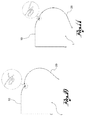
- the box 1 may be of any shape, in particular square, semi-square (see Figure 4 ) and semicircular (see Figure 12 ).
- the lower profile 20 is connected to the upper profile 10 by means of an extremal coupling portion 21 which engages a housing seat 11 made in an extremal portion 10' of the upper profile 10.
- the extremal portion 10' of the upper profile 10 has a substantially Z-shaped cross-section.
- the Z-shaped cross-section is defined by a first tract 13, which is distanced in relation to the main body 12 of the upper profile 10 on the inner side of the box, and by a second tract 14 which diagonally connects the first tract 13 to the main body 12.
- the first tract 13 may be parallel or not to the main body 12.
- the first tract 13 has an angled end portion 15, bent towards the main body 12, but distanced from it to define an access opening 16 to the housing seat 11.
- the housing seat 11 is thus delimited by the first tract 13, by the second tract 14 and by the end portion 15.
- the angled end portion 15 defines a flat surface 18 facing the seat 11 and forms with such surface an acute angle ⁇ in relation to the perpendicular p to a plane t1 which is tangent to the main body 12 of the upper profile next to the connection area 17, namely the area in which the main body 12 of the upper profile connects to the second connection tract 14.
- the conformation described above of the end portion 15 in relation to the main body 12 facilitates the insertion of the coupling portion 21 in the seat 11.
- the flat surface 18 of the end portion 15 is convergent towards the inside of the seat, so as to define an entry guide.
- the final spatial orientation of the end portion 15 depends on the conformation of the box.
- the housing seat 11 is made in part of the upper profile 10 positioned vertically and the angled end portion 15 thus results to be inclined downwards, with evident advantage in terms of ease of insertion of the coupling portion 21 in the seat 11.
- seat 11 can be made in a part of the profile positioned on a curved surface (i.e. on an inclined tangent plane) and the angled end portion 15 may not necessarily be inclined downwards.
- the conformation of the angled end portion 15 described above constitutes an advantage compared to the solutions of the prior art cited, in which even in the best situation of the upper profile being vertically positioned, the entrance to the housing seat results to be horizontal or even facing upwards.
- a semi-circular box (as shown in figure 13 ) it is possible to arrange the connection area between the two profiles in the curved area of the box with angles ⁇ of over 40° (up to values close to 50°) in relation to a plane m passing through the centre of the curve 0 of the circular area of the box 1.
- the coupling portion 21 comprises a tongue 23 engaging the housing seat 11 in a catching relation passing through the access opening 16.
- the tongue 23 is connected to the main body 22 of the lower profile by a connection tract with a double curve, which in particular defines an S-shaped cross-section.
- the coupling portion 21 has two humps 24 and 25 of opposed concavity, positioned at the connection tract of the tongue 23 to the main body 22 of the lower profile and corresponding to the aforesaid two curves.
- One hump 24 is proximal to the tongue 23 and the other hump 25 is distal in relation to said tongue.
- the coupling portion 21 is sized so that during its insertion inside the seat 11 the proximal hump 24 touches the angled end portion 15 next to or at the flat surface 18, while the distal hump 25 touches the main body 12 of the upper profile in the connection area 17.
- the flat surface 18 is inclined toward the inside of the seat 11 and thus guides toward the inside of the seat 11 the coupling portion 21, pushing it towards the main body 12 of the upper profile 10.
- the presence of the two humps 24 and 25 of opposed concavity accentuates the guide effect and at the same time ensures that there is contact between the lower profile and upper profile on the external side of the box 1, thus satisfying the aforementioned aesthetic requirements.
- An advantageous synergic effect between the conformation of the angled end portion 15 and the two hump conformation of the coupling portion 21 thus ensues.
- connection area 17 between the main body 12 of the upper profile and the second connection tract 14 is bevelled or rounded to determine a smooth sliding of the distal hump 25.
- connection area 17 has a curvilinear shape.
- each hump 24 or 25 is bevelled or rounded, and preferably has a curvilinear shape.
- the angled end portion 15 has an extremity 15a bent towards the outside of the seat.
- the extremity 15a is bevelled or rounded, to favour the insertion of the tongue 23 inside the seat.
- Such extremity 15a may also act as an abutment surface for the main body 22 of the lower profile 20.
- the abutment surface defined by the extremity 15a may, in particular, be flat with preferably bevelled or rounded corners.
- the tongue 23 of the coupling portion 21 is inclined towards a plane t2 tangent to the main body 22 next to the connection area with the tongue 23, in such a way that with the coupling portion 21 fully inserted in the seat 11 the tongue 23 is facing against the second connection tract 14 of the housing seat 11.
- the tongue 23 is sized to engage the aforesaid second tract 14, so as to guarantee coupling stability of the coupling portion 21 in the housing seat 11.
- the roller shutter box 1 according to the invention offers easy coupling of the lower profile while at the same time proving satisfactory from an aesthetic point of view without the need to make housing seats counter-shaped to the coupling portion. On the contrary, such effect is achieved by widening the entrance of the housing seat.
- the roller shutter box 1 makes it possible to position the joining area of the two profiles very close to the top of said box in the case in which the shutter box has a semicircular shape.
- the roller shutter box is lastly easy and economical to produce, given that the profiles 10 and 20 may be made by forming or pressing.
Landscapes
- Engineering & Computer Science (AREA)
- Structural Engineering (AREA)
- General Engineering & Computer Science (AREA)
- Architecture (AREA)
- Civil Engineering (AREA)
- Mechanical Engineering (AREA)
- Operating, Guiding And Securing Of Roll- Type Closing Members (AREA)
- Metal Rolling (AREA)
- Crystals, And After-Treatments Of Crystals (AREA)
- Electrochromic Elements, Electrophoresis, Or Variable Reflection Or Absorption Elements (AREA)
- Casings For Electric Apparatus (AREA)
- Closures For Containers (AREA)
Priority Applications (2)
| Application Number | Priority Date | Filing Date | Title |
|---|---|---|---|
| SI201330502A SI2828461T1 (sl) | 2012-03-23 | 2013-02-22 | Škatla za roleto |
| PL13716421T PL2828461T3 (pl) | 2012-03-23 | 2013-02-22 | Skrzynka na żaluzję zwijaną |
Applications Claiming Priority (2)
| Application Number | Priority Date | Filing Date | Title |
|---|---|---|---|
| IT000090A ITPD20120090A1 (it) | 2012-03-23 | 2012-03-23 | Cassonetto per avvolgibili |
| PCT/IB2013/051461 WO2013140277A1 (en) | 2012-03-23 | 2013-02-22 | Roller shutter box |
Publications (2)
| Publication Number | Publication Date |
|---|---|
| EP2828461A1 EP2828461A1 (en) | 2015-01-28 |
| EP2828461B1 true EP2828461B1 (en) | 2016-11-09 |
Family
ID=46548677
Family Applications (1)
| Application Number | Title | Priority Date | Filing Date |
|---|---|---|---|
| EP13716421.6A Active EP2828461B1 (en) | 2012-03-23 | 2013-02-22 | Roller shutter box |
Country Status (15)
| Country | Link |
|---|---|
| US (1) | US20150300079A1 (pl) |
| EP (1) | EP2828461B1 (pl) |
| CN (1) | CN104204392B (pl) |
| AU (1) | AU2013237116A1 (pl) |
| CA (1) | CA2864495A1 (pl) |
| EA (1) | EA024230B1 (pl) |
| ES (1) | ES2614483T3 (pl) |
| IN (1) | IN2014DN06934A (pl) |
| IT (1) | ITPD20120090A1 (pl) |
| MX (1) | MX2014011343A (pl) |
| PL (1) | PL2828461T3 (pl) |
| PT (1) | PT2828461T (pl) |
| SI (1) | SI2828461T1 (pl) |
| TN (1) | TN2014000335A1 (pl) |
| WO (1) | WO2013140277A1 (pl) |
Cited By (1)
| Publication number | Priority date | Publication date | Assignee | Title |
|---|---|---|---|---|
| EP3971384A1 (en) | 2020-09-15 | 2022-03-23 | Stec Kazimierz | Roller shutter box |
Families Citing this family (9)
| Publication number | Priority date | Publication date | Assignee | Title |
|---|---|---|---|---|
| US12044068B2 (en) | 2011-03-11 | 2024-07-23 | Lutron Technology Company Llc | Battery-powered motorized window treatment having a service position |
| US9045939B2 (en) | 2011-03-11 | 2015-06-02 | Lutron Electronics Co., Inc. | Battery-powered motorized window treatment having a service position |
| EP2757225B1 (en) * | 2011-03-11 | 2022-10-05 | Lutron Technology Company LLC | Low power radio frequency receiver |
| EP2986801B1 (en) | 2013-04-15 | 2020-07-15 | Lutron Technology Company LLC | Battery-powered roller shade with integrated accessible battery compartment |
| US10094169B2 (en) | 2014-11-01 | 2018-10-09 | Lutron Electronics Co., Inc. | Interlocking pivotable fascia for motorized window treatment |
| JP6453106B2 (ja) * | 2015-02-24 | 2019-01-16 | 三和シヤッター工業株式会社 | シャッターケース |
| JP6611599B2 (ja) * | 2015-12-25 | 2019-11-27 | 三和シヤッター工業株式会社 | シャッターケース |
| US10309153B2 (en) * | 2016-09-26 | 2019-06-04 | Draper, Inc. | Support system for rolled material |
| US10968693B2 (en) * | 2017-05-15 | 2021-04-06 | Hunter Douglas Industries Switzerland Gmbh | Valance assembly for a covering and associated packaging |
Family Cites Families (8)
| Publication number | Priority date | Publication date | Assignee | Title |
|---|---|---|---|---|
| DE3336805A1 (de) * | 1983-10-10 | 1985-04-25 | Alukon F. Grashei Kg, 8671 Konradsreuth | Rolladenkasten |
| FR2620765B1 (fr) * | 1987-09-23 | 1989-12-01 | Bubendorff Richard | Caisson pour volet roulant |
| DE4411997C1 (de) * | 1994-04-08 | 1995-06-14 | Achenbach Karl Gmbh | Rolladenkasten |
| DE10237006B4 (de) * | 2002-08-13 | 2008-04-30 | Roma Rolladensysteme Gmbh | Kasten zur Aufnahme eines aufwickelbaren Behangs. |
| US7111662B2 (en) * | 2004-10-05 | 2006-09-26 | Stephen Lukos | Roller tube having external slot for mounting screen material |
| CN2908744Y (zh) * | 2006-06-22 | 2007-06-06 | 大连舒心经贸有限公司 | 卷帘罩壳结构 |
| PL390881A1 (pl) | 2010-03-31 | 2011-10-10 | ALUPROF Spółka Akcyjna | Skrzynka rolety |
| CN201738779U (zh) * | 2010-07-15 | 2011-02-09 | 郎溪英之杰建筑科技有限公司 | 一种铝合金卷帘外罩壳 |
-
2012
- 2012-03-23 IT IT000090A patent/ITPD20120090A1/it unknown
-
2013
- 2013-02-22 WO PCT/IB2013/051461 patent/WO2013140277A1/en not_active Ceased
- 2013-02-22 US US14/387,539 patent/US20150300079A1/en not_active Abandoned
- 2013-02-22 EA EA201400902A patent/EA024230B1/ru not_active IP Right Cessation
- 2013-02-22 CA CA2864495A patent/CA2864495A1/en not_active Abandoned
- 2013-02-22 EP EP13716421.6A patent/EP2828461B1/en active Active
- 2013-02-22 CN CN201380016116.8A patent/CN104204392B/zh active Active
- 2013-02-22 SI SI201330502A patent/SI2828461T1/sl unknown
- 2013-02-22 MX MX2014011343A patent/MX2014011343A/es not_active Application Discontinuation
- 2013-02-22 AU AU2013237116A patent/AU2013237116A1/en not_active Abandoned
- 2013-02-22 PL PL13716421T patent/PL2828461T3/pl unknown
- 2013-02-22 ES ES13716421.6T patent/ES2614483T3/es active Active
- 2013-02-22 PT PT137164216T patent/PT2828461T/pt unknown
-
2014
- 2014-08-04 TN TNP2014000335A patent/TN2014000335A1/fr unknown
- 2014-08-19 IN IN6934DEN2014 patent/IN2014DN06934A/en unknown
Non-Patent Citations (1)
| Title |
|---|
| None * |
Cited By (1)
| Publication number | Priority date | Publication date | Assignee | Title |
|---|---|---|---|---|
| EP3971384A1 (en) | 2020-09-15 | 2022-03-23 | Stec Kazimierz | Roller shutter box |
Also Published As
| Publication number | Publication date |
|---|---|
| WO2013140277A1 (en) | 2013-09-26 |
| CN104204392A (zh) | 2014-12-10 |
| PT2828461T (pt) | 2017-02-07 |
| ITPD20120090A1 (it) | 2013-09-24 |
| MX2014011343A (es) | 2015-03-13 |
| EA201400902A1 (ru) | 2014-11-28 |
| PL2828461T3 (pl) | 2017-05-31 |
| SI2828461T1 (sl) | 2017-05-31 |
| EA024230B1 (ru) | 2016-08-31 |
| US20150300079A1 (en) | 2015-10-22 |
| ES2614483T3 (es) | 2017-05-31 |
| IN2014DN06934A (pl) | 2015-04-10 |
| EP2828461A1 (en) | 2015-01-28 |
| CA2864495A1 (en) | 2013-09-26 |
| CN104204392B (zh) | 2016-06-01 |
| AU2013237116A1 (en) | 2014-08-28 |
| TN2014000335A1 (en) | 2015-12-21 |
Similar Documents
| Publication | Publication Date | Title |
|---|---|---|
| EP2828461B1 (en) | Roller shutter box | |
| JP3176019U (ja) | 家具用挿入型連結部材 | |
| GB201207303D0 (en) | Corrugated tube protector | |
| USD815316S1 (en) | Slide clip with internal flanges | |
| JP2015194058A (ja) | 引違サッシの構造 | |
| WO2020228814A1 (zh) | 装饰板组件和端盖的装配结构及装饰板组件、空调器 | |
| CN106369796B (zh) | 一种空调面板及空调室内机 | |
| CN104279820A (zh) | 冰箱门体 | |
| US20130249369A1 (en) | Container rail for a drawer container | |
| TWD118725S1 (zh) | 修正帶施配器 | |
| CN116471966A (zh) | 拉出引导装置 | |
| EP2550571B1 (en) | Button push and pull mechanism | |
| CN105818725A (zh) | 一种车门内把手 | |
| CN207776374U (zh) | 踢脚线收口条 | |
| CN204207362U (zh) | 文件柜 | |
| KR102354150B1 (ko) | 도어 커버 서포터 조립구조 | |
| EP2374982B1 (en) | The box of a roller shutter | |
| US8950074B2 (en) | Slider for a cutter | |
| CN202613882U (zh) | 冷柜的门体结构 | |
| CN201348110Y (zh) | 管道连接快速卡扣 | |
| CN205373208U (zh) | 冰箱 | |
| JP7052177B2 (ja) | 出隅用土台水切 | |
| US1649214A (en) | Bracket and rod coupling for curtain fixtures | |
| WO2006036344A3 (en) | Safety pin with arcuate pin bar | |
| CN204218103U (zh) | 旁开扣 |
Legal Events
| Date | Code | Title | Description |
|---|---|---|---|
| PUAI | Public reference made under article 153(3) epc to a published international application that has entered the european phase |
Free format text: ORIGINAL CODE: 0009012 |
|
| 17P | Request for examination filed |
Effective date: 20140731 |
|
| AK | Designated contracting states |
Kind code of ref document: A1 Designated state(s): AL AT BE BG CH CY CZ DE DK EE ES FI FR GB GR HR HU IE IS IT LI LT LU LV MC MK MT NL NO PL PT RO RS SE SI SK SM TR |
|
| AX | Request for extension of the european patent |
Extension state: BA ME |
|
| DAX | Request for extension of the european patent (deleted) | ||
| GRAP | Despatch of communication of intention to grant a patent |
Free format text: ORIGINAL CODE: EPIDOSNIGR1 |
|
| INTG | Intention to grant announced |
Effective date: 20160725 |
|
| GRAS | Grant fee paid |
Free format text: ORIGINAL CODE: EPIDOSNIGR3 |
|
| GRAA | (expected) grant |
Free format text: ORIGINAL CODE: 0009210 |
|
| AK | Designated contracting states |
Kind code of ref document: B1 Designated state(s): AL AT BE BG CH CY CZ DE DK EE ES FI FR GB GR HR HU IE IS IT LI LT LU LV MC MK MT NL NO PL PT RO RS SE SI SK SM TR |
|
| REG | Reference to a national code |
Ref country code: GB Ref legal event code: FG4D |
|
| REG | Reference to a national code |
Ref country code: AT Ref legal event code: REF Ref document number: 844099 Country of ref document: AT Kind code of ref document: T Effective date: 20161115 Ref country code: CH Ref legal event code: EP |
|
| REG | Reference to a national code |
Ref country code: IE Ref legal event code: FG4D |
|
| REG | Reference to a national code |
Ref country code: DE Ref legal event code: R096 Ref document number: 602013013788 Country of ref document: DE |
|
| REG | Reference to a national code |
Ref country code: PT Ref legal event code: SC4A Ref document number: 2828461 Country of ref document: PT Date of ref document: 20170207 Kind code of ref document: T Free format text: AVAILABILITY OF NATIONAL TRANSLATION Effective date: 20170126 |
|
| REG | Reference to a national code |
Ref country code: CH Ref legal event code: NV Representative=s name: JACOBACCI AND PARTNERS SA, CH |
|
| PG25 | Lapsed in a contracting state [announced via postgrant information from national office to epo] |
Ref country code: LV Free format text: LAPSE BECAUSE OF FAILURE TO SUBMIT A TRANSLATION OF THE DESCRIPTION OR TO PAY THE FEE WITHIN THE PRESCRIBED TIME-LIMIT Effective date: 20161109 |
|
| REG | Reference to a national code |
Ref country code: FR Ref legal event code: PLFP Year of fee payment: 5 |
|
| REG | Reference to a national code |
Ref country code: LT Ref legal event code: MG4D |
|
| REG | Reference to a national code |
Ref country code: NL Ref legal event code: MP Effective date: 20161109 |
|
| PG25 | Lapsed in a contracting state [announced via postgrant information from national office to epo] |
Ref country code: NL Free format text: LAPSE BECAUSE OF FAILURE TO SUBMIT A TRANSLATION OF THE DESCRIPTION OR TO PAY THE FEE WITHIN THE PRESCRIBED TIME-LIMIT Effective date: 20161109 Ref country code: GR Free format text: LAPSE BECAUSE OF FAILURE TO SUBMIT A TRANSLATION OF THE DESCRIPTION OR TO PAY THE FEE WITHIN THE PRESCRIBED TIME-LIMIT Effective date: 20170210 Ref country code: NO Free format text: LAPSE BECAUSE OF FAILURE TO SUBMIT A TRANSLATION OF THE DESCRIPTION OR TO PAY THE FEE WITHIN THE PRESCRIBED TIME-LIMIT Effective date: 20170209 Ref country code: SE Free format text: LAPSE BECAUSE OF FAILURE TO SUBMIT A TRANSLATION OF THE DESCRIPTION OR TO PAY THE FEE WITHIN THE PRESCRIBED TIME-LIMIT Effective date: 20161109 Ref country code: LT Free format text: LAPSE BECAUSE OF FAILURE TO SUBMIT A TRANSLATION OF THE DESCRIPTION OR TO PAY THE FEE WITHIN THE PRESCRIBED TIME-LIMIT Effective date: 20161109 |
|
| PG25 | Lapsed in a contracting state [announced via postgrant information from national office to epo] |
Ref country code: HR Free format text: LAPSE BECAUSE OF FAILURE TO SUBMIT A TRANSLATION OF THE DESCRIPTION OR TO PAY THE FEE WITHIN THE PRESCRIBED TIME-LIMIT Effective date: 20161109 Ref country code: RS Free format text: LAPSE BECAUSE OF FAILURE TO SUBMIT A TRANSLATION OF THE DESCRIPTION OR TO PAY THE FEE WITHIN THE PRESCRIBED TIME-LIMIT Effective date: 20161109 Ref country code: FI Free format text: LAPSE BECAUSE OF FAILURE TO SUBMIT A TRANSLATION OF THE DESCRIPTION OR TO PAY THE FEE WITHIN THE PRESCRIBED TIME-LIMIT Effective date: 20161109 Ref country code: BE Free format text: LAPSE BECAUSE OF NON-PAYMENT OF DUE FEES Effective date: 20170228 Ref country code: IS Free format text: LAPSE BECAUSE OF FAILURE TO SUBMIT A TRANSLATION OF THE DESCRIPTION OR TO PAY THE FEE WITHIN THE PRESCRIBED TIME-LIMIT Effective date: 20170309 |
|
| REG | Reference to a national code |
Ref country code: ES Ref legal event code: FG2A Ref document number: 2614483 Country of ref document: ES Kind code of ref document: T3 Effective date: 20170531 |
|
| PG25 | Lapsed in a contracting state [announced via postgrant information from national office to epo] |
Ref country code: SK Free format text: LAPSE BECAUSE OF FAILURE TO SUBMIT A TRANSLATION OF THE DESCRIPTION OR TO PAY THE FEE WITHIN THE PRESCRIBED TIME-LIMIT Effective date: 20161109 Ref country code: EE Free format text: LAPSE BECAUSE OF FAILURE TO SUBMIT A TRANSLATION OF THE DESCRIPTION OR TO PAY THE FEE WITHIN THE PRESCRIBED TIME-LIMIT Effective date: 20161109 Ref country code: DK Free format text: LAPSE BECAUSE OF FAILURE TO SUBMIT A TRANSLATION OF THE DESCRIPTION OR TO PAY THE FEE WITHIN THE PRESCRIBED TIME-LIMIT Effective date: 20161109 Ref country code: RO Free format text: LAPSE BECAUSE OF FAILURE TO SUBMIT A TRANSLATION OF THE DESCRIPTION OR TO PAY THE FEE WITHIN THE PRESCRIBED TIME-LIMIT Effective date: 20161109 |
|
| REG | Reference to a national code |
Ref country code: DE Ref legal event code: R097 Ref document number: 602013013788 Country of ref document: DE |
|
| PG25 | Lapsed in a contracting state [announced via postgrant information from national office to epo] |
Ref country code: BG Free format text: LAPSE BECAUSE OF FAILURE TO SUBMIT A TRANSLATION OF THE DESCRIPTION OR TO PAY THE FEE WITHIN THE PRESCRIBED TIME-LIMIT Effective date: 20170209 Ref country code: BE Free format text: LAPSE BECAUSE OF FAILURE TO SUBMIT A TRANSLATION OF THE DESCRIPTION OR TO PAY THE FEE WITHIN THE PRESCRIBED TIME-LIMIT Effective date: 20161109 Ref country code: SM Free format text: LAPSE BECAUSE OF FAILURE TO SUBMIT A TRANSLATION OF THE DESCRIPTION OR TO PAY THE FEE WITHIN THE PRESCRIBED TIME-LIMIT Effective date: 20161109 |
|
| PLBE | No opposition filed within time limit |
Free format text: ORIGINAL CODE: 0009261 |
|
| STAA | Information on the status of an ep patent application or granted ep patent |
Free format text: STATUS: NO OPPOSITION FILED WITHIN TIME LIMIT |
|
| PG25 | Lapsed in a contracting state [announced via postgrant information from national office to epo] |
Ref country code: MC Free format text: LAPSE BECAUSE OF FAILURE TO SUBMIT A TRANSLATION OF THE DESCRIPTION OR TO PAY THE FEE WITHIN THE PRESCRIBED TIME-LIMIT Effective date: 20161109 |
|
| 26N | No opposition filed |
Effective date: 20170810 |
|
| GBPC | Gb: european patent ceased through non-payment of renewal fee |
Effective date: 20170222 |
|
| REG | Reference to a national code |
Ref country code: IE Ref legal event code: MM4A |
|
| PG25 | Lapsed in a contracting state [announced via postgrant information from national office to epo] |
Ref country code: LU Free format text: LAPSE BECAUSE OF NON-PAYMENT OF DUE FEES Effective date: 20170222 |
|
| PG25 | Lapsed in a contracting state [announced via postgrant information from national office to epo] |
Ref country code: IE Free format text: LAPSE BECAUSE OF NON-PAYMENT OF DUE FEES Effective date: 20170222 Ref country code: GB Free format text: LAPSE BECAUSE OF NON-PAYMENT OF DUE FEES Effective date: 20170222 |
|
| REG | Reference to a national code |
Ref country code: FR Ref legal event code: PLFP Year of fee payment: 6 |
|
| PG25 | Lapsed in a contracting state [announced via postgrant information from national office to epo] |
Ref country code: MT Free format text: LAPSE BECAUSE OF NON-PAYMENT OF DUE FEES Effective date: 20170222 |
|
| PG25 | Lapsed in a contracting state [announced via postgrant information from national office to epo] |
Ref country code: HU Free format text: LAPSE BECAUSE OF FAILURE TO SUBMIT A TRANSLATION OF THE DESCRIPTION OR TO PAY THE FEE WITHIN THE PRESCRIBED TIME-LIMIT; INVALID AB INITIO Effective date: 20130222 |
|
| REG | Reference to a national code |
Ref country code: AT Ref legal event code: UEP Ref document number: 844099 Country of ref document: AT Kind code of ref document: T Effective date: 20161109 |
|
| PG25 | Lapsed in a contracting state [announced via postgrant information from national office to epo] |
Ref country code: CY Free format text: LAPSE BECAUSE OF FAILURE TO SUBMIT A TRANSLATION OF THE DESCRIPTION OR TO PAY THE FEE WITHIN THE PRESCRIBED TIME-LIMIT Effective date: 20161109 |
|
| PG25 | Lapsed in a contracting state [announced via postgrant information from national office to epo] |
Ref country code: MK Free format text: LAPSE BECAUSE OF FAILURE TO SUBMIT A TRANSLATION OF THE DESCRIPTION OR TO PAY THE FEE WITHIN THE PRESCRIBED TIME-LIMIT Effective date: 20161109 |
|
| PG25 | Lapsed in a contracting state [announced via postgrant information from national office to epo] |
Ref country code: AL Free format text: LAPSE BECAUSE OF FAILURE TO SUBMIT A TRANSLATION OF THE DESCRIPTION OR TO PAY THE FEE WITHIN THE PRESCRIBED TIME-LIMIT Effective date: 20161109 |
|
| P01 | Opt-out of the competence of the unified patent court (upc) registered |
Effective date: 20230526 |
|
| PGFP | Annual fee paid to national office [announced via postgrant information from national office to epo] |
Ref country code: PT Payment date: 20231222 Year of fee payment: 12 |
|
| PGFP | Annual fee paid to national office [announced via postgrant information from national office to epo] |
Ref country code: CZ Payment date: 20240102 Year of fee payment: 12 Ref country code: CH Payment date: 20240301 Year of fee payment: 12 |
|
| PGFP | Annual fee paid to national office [announced via postgrant information from national office to epo] |
Ref country code: SI Payment date: 20240208 Year of fee payment: 12 |
|
| PGFP | Annual fee paid to national office [announced via postgrant information from national office to epo] |
Ref country code: TR Payment date: 20240219 Year of fee payment: 12 |
|
| PGFP | Annual fee paid to national office [announced via postgrant information from national office to epo] |
Ref country code: DE Payment date: 20250225 Year of fee payment: 13 |
|
| PGFP | Annual fee paid to national office [announced via postgrant information from national office to epo] |
Ref country code: ES Payment date: 20250303 Year of fee payment: 13 |
|
| PGFP | Annual fee paid to national office [announced via postgrant information from national office to epo] |
Ref country code: AT Payment date: 20250217 Year of fee payment: 13 |
|
| PGFP | Annual fee paid to national office [announced via postgrant information from national office to epo] |
Ref country code: FR Payment date: 20250130 Year of fee payment: 13 Ref country code: PL Payment date: 20250130 Year of fee payment: 13 |
|
| PGFP | Annual fee paid to national office [announced via postgrant information from national office to epo] |
Ref country code: IT Payment date: 20241114 Year of fee payment: 13 |
|
| REG | Reference to a national code |
Ref country code: CH Ref legal event code: PL |
|
| PG25 | Lapsed in a contracting state [announced via postgrant information from national office to epo] |
Ref country code: PT Free format text: LAPSE BECAUSE OF NON-PAYMENT OF DUE FEES Effective date: 20250822 |
|
| PG25 | Lapsed in a contracting state [announced via postgrant information from national office to epo] |
Ref country code: CH Free format text: LAPSE BECAUSE OF NON-PAYMENT OF DUE FEES Effective date: 20250228 |
|
| PG25 | Lapsed in a contracting state [announced via postgrant information from national office to epo] |
Ref country code: CZ Free format text: LAPSE BECAUSE OF NON-PAYMENT OF DUE FEES Effective date: 20250222 |