EP2827786B1 - Chirurgisches fräsinstrument - Google Patents
Chirurgisches fräsinstrument Download PDFInfo
- Publication number
- EP2827786B1 EP2827786B1 EP13713746.9A EP13713746A EP2827786B1 EP 2827786 B1 EP2827786 B1 EP 2827786B1 EP 13713746 A EP13713746 A EP 13713746A EP 2827786 B1 EP2827786 B1 EP 2827786B1
- Authority
- EP
- European Patent Office
- Prior art keywords
- insert plate
- hole
- milling instrument
- shaft tube
- end piece
- Prior art date
- Legal status (The legal status is an assumption and is not a legal conclusion. Google has not performed a legal analysis and makes no representation as to the accuracy of the status listed.)
- Not-in-force
Links
- 238000003801 milling Methods 0.000 title claims description 16
- 238000004519 manufacturing process Methods 0.000 claims description 11
- 238000005520 cutting process Methods 0.000 claims description 9
- 239000000463 material Substances 0.000 description 4
- 238000003466 welding Methods 0.000 description 3
- 238000003860 storage Methods 0.000 description 2
- 210000001015 abdomen Anatomy 0.000 description 1
- 239000000919 ceramic Substances 0.000 description 1
- 238000010276 construction Methods 0.000 description 1
- 230000006378 damage Effects 0.000 description 1
- 230000000694 effects Effects 0.000 description 1
- 238000005516 engineering process Methods 0.000 description 1
- 230000007774 longterm Effects 0.000 description 1
- 238000003754 machining Methods 0.000 description 1
- 230000002093 peripheral effect Effects 0.000 description 1
- 238000003825 pressing Methods 0.000 description 1
- 238000010008 shearing Methods 0.000 description 1
- 238000005476 soldering Methods 0.000 description 1
- 238000009987 spinning Methods 0.000 description 1
Images


Classifications
-
- A—HUMAN NECESSITIES
- A61—MEDICAL OR VETERINARY SCIENCE; HYGIENE
- A61B—DIAGNOSIS; SURGERY; IDENTIFICATION
- A61B17/00—Surgical instruments, devices or methods
- A61B17/32—Surgical cutting instruments
- A61B17/320016—Endoscopic cutting instruments, e.g. arthroscopes, resectoscopes
-
- A—HUMAN NECESSITIES
- A61—MEDICAL OR VETERINARY SCIENCE; HYGIENE
- A61B—DIAGNOSIS; SURGERY; IDENTIFICATION
- A61B17/00—Surgical instruments, devices or methods
- A61B17/32—Surgical cutting instruments
- A61B17/320016—Endoscopic cutting instruments, e.g. arthroscopes, resectoscopes
- A61B17/32002—Endoscopic cutting instruments, e.g. arthroscopes, resectoscopes with continuously rotating, oscillating or reciprocating cutting instruments
-
- A—HUMAN NECESSITIES
- A61—MEDICAL OR VETERINARY SCIENCE; HYGIENE
- A61B—DIAGNOSIS; SURGERY; IDENTIFICATION
- A61B17/00—Surgical instruments, devices or methods
- A61B17/32—Surgical cutting instruments
- A61B17/3205—Excision instruments
-
- A—HUMAN NECESSITIES
- A61—MEDICAL OR VETERINARY SCIENCE; HYGIENE
- A61B—DIAGNOSIS; SURGERY; IDENTIFICATION
- A61B17/00—Surgical instruments, devices or methods
- A61B2017/00831—Material properties
- A61B2017/0084—Material properties low friction
- A61B2017/00845—Material properties low friction of moving parts with respect to each other
-
- A—HUMAN NECESSITIES
- A61—MEDICAL OR VETERINARY SCIENCE; HYGIENE
- A61B—DIAGNOSIS; SURGERY; IDENTIFICATION
- A61B17/00—Surgical instruments, devices or methods
- A61B2017/00831—Material properties
- A61B2017/0088—Material properties ceramic
Definitions
- the invention relates to a surgical Fräsinstrument mentioned in the preamble of claim 1 and a tube diameter of the Fräsinstrumentes and a method for producing the tubular blade.
- a generic milling instrument is from the EP 0 807 413 A1 on which the preamble of claim 1 is based. It is used for milling removal of body tissue of all kinds and is used in particular endoscopically, for which purpose it is suitable with an elongated shaft tube.
- the tube knives are attached to a main body, namely the outer tube knives rotationally fixed and the inner tube knife rotationally driven. This is in the main body z. B. provided an electric motor.
- the length of the shaft tubes is adapted to the surgical conditions, eg. As working in a joint or in the abdomen.
- the inner tube turns at high speed.
- the cutting windows are moved in the shaft tubes relative to each other. In The tissue entering the cutting windows is cut off from each other by shearing movement of the edges of the cutting windows.
- the tube diameter must slide as closely as possible to each other and require for good long-term safe operation at high speed good storage together.
- bearings are provided between the cylindrical shaft tubes. In the region of the hemispherical end pieces, an axial bearing of the shaft tubes together is required.
- the hemispherical end pieces lie all over one another for axial mounting. Although this results in a good axial bearing but also a radial bearing in the ball area.
- the shaft tube is pulled at the distal end by pressing in the spherical shape and thereby closed except for a small hole, which must be closed very materially material.
- the object of the present invention is to inexpensively improve the problems of axial bearing in a generic milling instrument.
- an insert plate is inserted in an end piece, surrounding the axis of the shaft tube. This eliminates the need to close the hole remaining when the tube is pressed. Since the plate is used, it can be processed separately from the tube and can be easily formed in a suitable manner for the axial bearing. This work on the plate can be made much easier if it is still separated from the tube knife.
- the end pieces can be formed with their insert plate exactly hemispherical, which would then in the region of the end pieces in addition to the axial bearing and a radial bearing would result, which is undesirable. Therefore, care should be taken that in the region of the hemispherical distal end pieces only axial contact, but no radial contact is given.
- the features of claim 2 are advantageously provided. If an insert plate with the center of its lying to the other end surface projecting beyond the spherical surface, then results in the region of this projecting center, the axial abutment between the two distal end pieces, resulting in a very clean axial bearing position and without radial guidance.
- this design of the insert plate can be provided both on the outer tube knife, as well as on the inner tube diameter. At the outer tube knife, the plate must be projecting inwardly and projecting outwardly on the inner tube knife.
- the inner surface of the insert plate is flat.
- the flat inner surface provides good abutment for the projecting portion of the insert plate on the inner tube knife, avoiding any radial guidance in this area.
- the outer surface of the insert plate formed as part of the spherical surface. It thus results on the outside of the pipe diameter a completely undisturbed spherical surface, which z. B. injuries can be avoided.
- both insert plates may be formed identically, which facilitates the storage and the costs.
- the insert plate may have largely any peripheral shape, z. B. quadrangular.
- the hole in the end piece, which is to receive the insert plate, must then be prepared accordingly.
- this hole is formed as a bore arranged concentrically to the axis of the associated shaft tube, whereby the production of the hole in rotary machining is greatly simplified.
- the matching insert plate with cylindrical edge surface can be produced inexpensively.
- Claim 7 protects the tube diameter of the milling instrument.
- the tubular knife according to the invention can be prepared in different ways, preferably according to claim 8. Initially, preferably in rotating operation, one end of the shaft tube is pressed into the hemispherical shape until there remains a small opening which is smaller than the hole in the the insert plate is to be used. Then then the hole for the insert plate, z. B. introduced with a drill to then use the insert plate in this hole and finally connect to the edge of the shaft tube, for example by soldering, welding or the like.
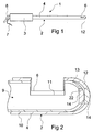
- Fig. 1 shows an inventive milling instrument 1 with an outer tube knife 2, which is fixed to a main body 3.
- the main body 3 can be used as a handle and be designed accordingly.
- the outer tube knife 2 has an elongated cylindrical shaft tube 4 and a hemispherical distal end piece 12. Near the distal end piece 12, a cutting window 6 is formed in the tube knife 2.
- the main body 3 is a in the Fig. 1 arranged invisible electric motor, which is supplied via a outgoing from the main body 3 to the outside cable 7.
- the z. B. is connected to a suitable suction device to aspirate from the interior of the shaft tube 4.
- Fig. 2 shows in enlarged section the distal end portion of the outer tube diameter 2. It can be seen that in this an inner tube knife 9 is arranged, which is arranged with its cylindrical shaft tube 10 in the cylindrical shaft tube 4 of the outer tube diameter 2 in good axial bearing. At the location of the cutting window 6 in the outer tube knife 2, the inner tube knife 9 has a matching cutting window 11th
- the inner tube knife 9 is driven by the motor in the main body 3 and rotates about the common axis of the two tube knives 2 and 9. In this case, the cutting windows 6 and 11 move relative to each other so that their edges cut off invading tissue. At high speed results in a very good milling action. Milled material passes through the cutting window 6, 11 into the interior of the inner tube diameter 9 and is sucked from there via the suction hose 8.
- Fig. 2 shows that the distal end portion 12 of the outer tube knife 2 as well as the distal end portion 13 of the inner tube diameter 9 are formed in a semi-spherical spherical shape. If the distal end pieces 12 and 13 were arranged as in the EP 0 807 413 A1 is described, the inner surface of the outer end piece 12 would correspond exactly to the outer surface of the inner end piece 13 and this abut surface.
- the inventive training according to Fig. 2 ensures that a support of the tube diameter 2 and 9 together only results in a point that lies in the axis of the tube knife.
- the other areas of the hemispherical surfaces are kept at a distance, so that in the end pieces 12 and 13 results in no axially supporting investment of the spherical surfaces.
- both end pieces 12 and 13 can be formed identical in this central region.
- the central portions of the end pieces 12 and 13 are formed as identical insert plates 14. This greatly simplifies the manufacture of the central portions of the end pieces 12 and 13 which require a precise fit.
- the insert plates 14 can be made in a completely different way than the remaining parts of the tube knives.
- Fig. 3 shows otherwise with the representation of Fig. 2 coincident, omitted for drawing simplification training only the two insert plates, but here in a different training.
- the insert plate 14 of the inner tube diameter 9 corresponds to the training of Fig. 2 .
- the insert plate 15 in the outer tube knife 2 is flat on its inner surface, as well as the insert plate 14, but in this embodiment also on the outer surface, which is shown here as an example of a possible embodiment.
- Fig. 4 shows a further variant of the insert plates, wherein the insert plate on the inner tube knife is the flat on both surfaces plate 15 and the outer insert plate 16 is of a completely different shape. It projects inwards with a bulge 17.
- Fig. 5 Yet another variant of the axial bearing is shown.
- the outer end piece 12 is formed without insert plate.
- an insert plate 18 is arranged, which has a clear projection 19 in the distal direction.
- the outer end piece 12 may be formed for reasons of ease of manufacture with an insert plate which would have spherical shape on both surfaces.
- FIGS. 6 and 8 serve to explain an advantageous method for producing the tube knife 2, which can also be used for the production of the tube knife 9, which may be formed identical to the diameter, as the Fig. 2 shows.
- the pipe section 4 is z. B. rotatably driven on a lathe and rotatably deformed in its illustrated end with a spinning tool, so that the illustrated end in the diameter is drawn ever narrower until the in Fig. 7 illustrated rounded shape of the end piece 12 results.
- a in Fig. 7 illustrated straight tool 20 are used, which is gradually bent over the positions 20, 20 ', 20 "more and more, to thereby the pipe 4 from the straight shape according to Fig. 6 in the rounded form according to Fig. 7 to press.
- a bore 22 is introduced, which in its diameter to the outer diameter of the insert plates, z. B. the insert plate 14 according to Fig. 2 fits. Therein can then insert plate 14 are used, as in Fig. 2 is shown, and attached to the edge, z. B. by welding.
- the insert plates 14, 15, 16 or 18 are exposed to the point of their contact increased wear and therefore advantageously consist of a special wear-resistant material such. Carbide or ceramic.
Landscapes
- Health & Medical Sciences (AREA)
- Surgery (AREA)
- Life Sciences & Earth Sciences (AREA)
- Biomedical Technology (AREA)
- Nuclear Medicine, Radiotherapy & Molecular Imaging (AREA)
- Engineering & Computer Science (AREA)
- Heart & Thoracic Surgery (AREA)
- Medical Informatics (AREA)
- Molecular Biology (AREA)
- Animal Behavior & Ethology (AREA)
- General Health & Medical Sciences (AREA)
- Public Health (AREA)
- Veterinary Medicine (AREA)
- Orthopedic Medicine & Surgery (AREA)
- Surgical Instruments (AREA)
Applications Claiming Priority (2)
| Application Number | Priority Date | Filing Date | Title |
|---|---|---|---|
| DE102012005536A DE102012005536A1 (de) | 2012-03-21 | 2012-03-21 | Chirurgisches Fräsinstrument |
| PCT/EP2013/000839 WO2013139473A1 (de) | 2012-03-21 | 2013-03-20 | Chirurgisches fräsinstrument |
Publications (2)
| Publication Number | Publication Date |
|---|---|
| EP2827786A1 EP2827786A1 (de) | 2015-01-28 |
| EP2827786B1 true EP2827786B1 (de) | 2016-05-18 |
Family
ID=48045403
Family Applications (1)
| Application Number | Title | Priority Date | Filing Date |
|---|---|---|---|
| EP13713746.9A Not-in-force EP2827786B1 (de) | 2012-03-21 | 2013-03-20 | Chirurgisches fräsinstrument |
Country Status (7)
Families Citing this family (8)
| Publication number | Priority date | Publication date | Assignee | Title |
|---|---|---|---|---|
| DE102014206976A1 (de) * | 2014-04-10 | 2015-10-15 | OLYMPUS Winter & lbe GmbH | Elektrochirurgisches Instrument und Verfahren zum Einführen eines Applikators in Körperlumen |
| JP2016083298A (ja) * | 2014-10-28 | 2016-05-19 | テルモ株式会社 | 血栓吸引カテーテルおよびその使用方法 |
| EP3361971B1 (en) * | 2015-10-14 | 2024-01-17 | Corinth Medtech, Inc. | Surgical device |
| WO2017180423A1 (en) * | 2016-04-14 | 2017-10-19 | Smith & Nephew, Inc | Cutting tool with bearing |
| US11826068B2 (en) | 2018-12-10 | 2023-11-28 | Acclarent, Inc. | Method of forming suction instrument end and shaver instrument end |
| CN109893175A (zh) * | 2019-02-28 | 2019-06-18 | 成都真实维度科技有限公司 | 一种通过激光引导进行穿刺活检的装置 |
| CN110755133A (zh) * | 2019-11-19 | 2020-02-07 | 昆山金泰医疗科技有限公司 | 一种旋切装置 |
| GB2598332B (en) | 2020-08-26 | 2024-07-24 | Gyrus Medical Ltd | Electrosurgical instrument |
Family Cites Families (11)
| Publication number | Priority date | Publication date | Assignee | Title |
|---|---|---|---|---|
| US4603694A (en) * | 1983-03-08 | 1986-08-05 | Richards Medical Company | Arthroscopic shaver |
| US4660267A (en) * | 1983-03-08 | 1987-04-28 | Richards Medical Company | Method for fabricating an arthroscopic shaver |
| JPH06114070A (ja) * | 1990-06-22 | 1994-04-26 | Vance Prod Inc | 外科用組織切除装置 |
| US5275609A (en) * | 1990-06-22 | 1994-01-04 | Vance Products Incorporated | Surgical cutting instrument |
| WO1994026181A1 (en) * | 1993-05-07 | 1994-11-24 | Danek Medical, Inc. | Surgical cutting instrument |
| US5665101A (en) * | 1996-04-01 | 1997-09-09 | Linvatec Corporation | Endoscopic or open lipectomy instrument |
| CN2368459Y (zh) | 1999-03-24 | 2000-03-15 | 郭自明 | 医疗用旋切器 |
| CN2576177Y (zh) | 2002-08-08 | 2003-10-01 | 任维丽 | 旋切式病理软组织穿刺活检针 |
| CN2822524Y (zh) | 2005-08-08 | 2006-10-04 | 苗诚 | 负压抽吸旋切式活检针 |
| US8177803B2 (en) * | 2006-07-19 | 2012-05-15 | Target Medical Innovations, LLC | Endoscopic cutting instruments having improved cutting efficiency and reduced manufacturing costs |
| US7666200B2 (en) * | 2006-07-19 | 2010-02-23 | Target Medical Innovations Llc | Endoscopic cutting instrument with axial and rotary motion |
-
2012
- 2012-03-21 DE DE102012005536A patent/DE102012005536A1/de not_active Withdrawn
-
2013
- 2013-03-20 EP EP13713746.9A patent/EP2827786B1/de not_active Not-in-force
- 2013-03-20 AU AU2013234750A patent/AU2013234750B2/en not_active Ceased
- 2013-03-20 JP JP2015500795A patent/JP5956671B2/ja not_active Expired - Fee Related
- 2013-03-20 WO PCT/EP2013/000839 patent/WO2013139473A1/de active Application Filing
- 2013-03-20 CN CN201380014994.6A patent/CN104203127B/zh not_active Expired - Fee Related
- 2013-03-20 US US14/386,066 patent/US9433432B2/en not_active Expired - Fee Related
Also Published As
| Publication number | Publication date |
|---|---|
| US9433432B2 (en) | 2016-09-06 |
| EP2827786A1 (de) | 2015-01-28 |
| JP5956671B2 (ja) | 2016-07-27 |
| DE102012005536A1 (de) | 2013-09-26 |
| AU2013234750B2 (en) | 2016-07-14 |
| WO2013139473A1 (de) | 2013-09-26 |
| US20150051628A1 (en) | 2015-02-19 |
| JP2015512699A (ja) | 2015-04-30 |
| AU2013234750A1 (en) | 2014-10-09 |
| CN104203127A (zh) | 2014-12-10 |
| CN104203127B (zh) | 2016-09-28 |
Similar Documents
| Publication | Publication Date | Title |
|---|---|---|
| EP2827786B1 (de) | Chirurgisches fräsinstrument | |
| DE69731786T2 (de) | Endoskopische Schaberklinge mit federnden Schneidkanten | |
| EP2825339B1 (de) | Verfahren und entgratwerkzeug zur entgratung von insbesondere unrunden ausnehmungen in werkstücken | |
| EP2434966A1 (de) | Chirurgisches instrument | |
| EP2434965B1 (de) | Chirurgisches instrument | |
| EP3528688B1 (de) | Medizinische vorrichtung | |
| DE8904260U1 (de) | Medizinischer Katheter mit Schneidvorrichtung | |
| EP0605763A1 (de) | Gewebestanze | |
| DE102009049087B4 (de) | Bohrer | |
| DE602005005599T2 (de) | Plansenker für Oberschenkelkopfgelenkpfanne. | |
| DE2814568C2 (de) | Werkzeug zum fraesen von nuten in holz, kunststoff und aehnlichem material | |
| EP1857223B1 (de) | Oszillationsantrieb mit einem Tiefenanschlag und Tiefenanschlag für einen Oszillationsantrieb | |
| EP1543903A1 (de) | Rohrendbearbeitungsvorrichtung | |
| WO2008145380A1 (de) | Chirurgisches instrument sowie verfahren zu dessen herstellung | |
| DE102004014659A1 (de) | Entgratmesser zum Entgraten von Bohrungsrändern | |
| DE10393499B4 (de) | Resektoskop mit positionierter Optik | |
| DE102009037045A1 (de) | Rohrförmiger Schaft eines chirurgischen Instruments | |
| DE102009057115A1 (de) | Rohrschneideverfahren und Vorrichtung | |
| WO2007140846A2 (de) | Probenahmevorrichtung, insbesondere biopsienadel | |
| DE202007016817U1 (de) | Werkzeug zur spanenden Bearbeitung von Werkstücken | |
| EP2229110A1 (de) | Aufsatzvorrichtung für eine chirurgische vorrichtung sowie chirurgische vorrichtung zum durchschneiden eines knochens | |
| DE3408243A1 (de) | Urethrotom fuer die harnroehrenerweiterung | |
| DE202016008660U1 (de) | Zangenlöffelanordnung für eine Biopsiezange und Biopsiezange zur Entnahme von Hirngewebeproben | |
| DE102017208567B4 (de) | Entgratwerkzeug zum Entgraten von Bohrungsverschneidungen | |
| DE202015103536U1 (de) | Medizinisches Instrument zum Abtragen von Weichgewebe oder Knorpel |
Legal Events
| Date | Code | Title | Description |
|---|---|---|---|
| PUAI | Public reference made under article 153(3) epc to a published international application that has entered the european phase |
Free format text: ORIGINAL CODE: 0009012 |
|
| 17P | Request for examination filed |
Effective date: 20140922 |
|
| AK | Designated contracting states |
Kind code of ref document: A1 Designated state(s): AL AT BE BG CH CY CZ DE DK EE ES FI FR GB GR HR HU IE IS IT LI LT LU LV MC MK MT NL NO PL PT RO RS SE SI SK SM TR |
|
| AX | Request for extension of the european patent |
Extension state: BA ME |
|
| DAX | Request for extension of the european patent (deleted) | ||
| GRAP | Despatch of communication of intention to grant a patent |
Free format text: ORIGINAL CODE: EPIDOSNIGR1 |
|
| INTG | Intention to grant announced |
Effective date: 20151029 |
|
| GRAS | Grant fee paid |
Free format text: ORIGINAL CODE: EPIDOSNIGR3 |
|
| GRAA | (expected) grant |
Free format text: ORIGINAL CODE: 0009210 |
|
| AK | Designated contracting states |
Kind code of ref document: B1 Designated state(s): AL AT BE BG CH CY CZ DE DK EE ES FI FR GB GR HR HU IE IS IT LI LT LU LV MC MK MT NL NO PL PT RO RS SE SI SK SM TR |
|
| REG | Reference to a national code |
Ref country code: GB Ref legal event code: FG4D Free format text: NOT ENGLISH |
|
| REG | Reference to a national code |
Ref country code: CH Ref legal event code: EP |
|
| REG | Reference to a national code |
Ref country code: IE Ref legal event code: FG4D Free format text: LANGUAGE OF EP DOCUMENT: GERMAN Ref country code: AT Ref legal event code: REF Ref document number: 799700 Country of ref document: AT Kind code of ref document: T Effective date: 20160615 |
|
| REG | Reference to a national code |
Ref country code: DE Ref legal event code: R096 Ref document number: 502013003063 Country of ref document: DE |
|
| REG | Reference to a national code |
Ref country code: NL Ref legal event code: MP Effective date: 20160518 |
|
| REG | Reference to a national code |
Ref country code: LT Ref legal event code: MG4D |
|
| PG25 | Lapsed in a contracting state [announced via postgrant information from national office to epo] |
Ref country code: LT Free format text: LAPSE BECAUSE OF FAILURE TO SUBMIT A TRANSLATION OF THE DESCRIPTION OR TO PAY THE FEE WITHIN THE PRESCRIBED TIME-LIMIT Effective date: 20160518 Ref country code: NL Free format text: LAPSE BECAUSE OF FAILURE TO SUBMIT A TRANSLATION OF THE DESCRIPTION OR TO PAY THE FEE WITHIN THE PRESCRIBED TIME-LIMIT Effective date: 20160518 Ref country code: FI Free format text: LAPSE BECAUSE OF FAILURE TO SUBMIT A TRANSLATION OF THE DESCRIPTION OR TO PAY THE FEE WITHIN THE PRESCRIBED TIME-LIMIT Effective date: 20160518 Ref country code: NO Free format text: LAPSE BECAUSE OF FAILURE TO SUBMIT A TRANSLATION OF THE DESCRIPTION OR TO PAY THE FEE WITHIN THE PRESCRIBED TIME-LIMIT Effective date: 20160818 |
|
| PG25 | Lapsed in a contracting state [announced via postgrant information from national office to epo] |
Ref country code: SE Free format text: LAPSE BECAUSE OF FAILURE TO SUBMIT A TRANSLATION OF THE DESCRIPTION OR TO PAY THE FEE WITHIN THE PRESCRIBED TIME-LIMIT Effective date: 20160518 Ref country code: RS Free format text: LAPSE BECAUSE OF FAILURE TO SUBMIT A TRANSLATION OF THE DESCRIPTION OR TO PAY THE FEE WITHIN THE PRESCRIBED TIME-LIMIT Effective date: 20160518 Ref country code: HR Free format text: LAPSE BECAUSE OF FAILURE TO SUBMIT A TRANSLATION OF THE DESCRIPTION OR TO PAY THE FEE WITHIN THE PRESCRIBED TIME-LIMIT Effective date: 20160518 Ref country code: PT Free format text: LAPSE BECAUSE OF FAILURE TO SUBMIT A TRANSLATION OF THE DESCRIPTION OR TO PAY THE FEE WITHIN THE PRESCRIBED TIME-LIMIT Effective date: 20160919 Ref country code: LV Free format text: LAPSE BECAUSE OF FAILURE TO SUBMIT A TRANSLATION OF THE DESCRIPTION OR TO PAY THE FEE WITHIN THE PRESCRIBED TIME-LIMIT Effective date: 20160518 Ref country code: ES Free format text: LAPSE BECAUSE OF FAILURE TO SUBMIT A TRANSLATION OF THE DESCRIPTION OR TO PAY THE FEE WITHIN THE PRESCRIBED TIME-LIMIT Effective date: 20160518 Ref country code: GR Free format text: LAPSE BECAUSE OF FAILURE TO SUBMIT A TRANSLATION OF THE DESCRIPTION OR TO PAY THE FEE WITHIN THE PRESCRIBED TIME-LIMIT Effective date: 20160819 |
|
| PG25 | Lapsed in a contracting state [announced via postgrant information from national office to epo] |
Ref country code: IT Free format text: LAPSE BECAUSE OF FAILURE TO SUBMIT A TRANSLATION OF THE DESCRIPTION OR TO PAY THE FEE WITHIN THE PRESCRIBED TIME-LIMIT Effective date: 20160518 |
|
| PG25 | Lapsed in a contracting state [announced via postgrant information from national office to epo] |
Ref country code: DK Free format text: LAPSE BECAUSE OF FAILURE TO SUBMIT A TRANSLATION OF THE DESCRIPTION OR TO PAY THE FEE WITHIN THE PRESCRIBED TIME-LIMIT Effective date: 20160518 Ref country code: EE Free format text: LAPSE BECAUSE OF FAILURE TO SUBMIT A TRANSLATION OF THE DESCRIPTION OR TO PAY THE FEE WITHIN THE PRESCRIBED TIME-LIMIT Effective date: 20160518 Ref country code: SK Free format text: LAPSE BECAUSE OF FAILURE TO SUBMIT A TRANSLATION OF THE DESCRIPTION OR TO PAY THE FEE WITHIN THE PRESCRIBED TIME-LIMIT Effective date: 20160518 Ref country code: CZ Free format text: LAPSE BECAUSE OF FAILURE TO SUBMIT A TRANSLATION OF THE DESCRIPTION OR TO PAY THE FEE WITHIN THE PRESCRIBED TIME-LIMIT Effective date: 20160518 Ref country code: RO Free format text: LAPSE BECAUSE OF FAILURE TO SUBMIT A TRANSLATION OF THE DESCRIPTION OR TO PAY THE FEE WITHIN THE PRESCRIBED TIME-LIMIT Effective date: 20160518 |
|
| REG | Reference to a national code |
Ref country code: DE Ref legal event code: R097 Ref document number: 502013003063 Country of ref document: DE |
|
| PG25 | Lapsed in a contracting state [announced via postgrant information from national office to epo] |
Ref country code: SM Free format text: LAPSE BECAUSE OF FAILURE TO SUBMIT A TRANSLATION OF THE DESCRIPTION OR TO PAY THE FEE WITHIN THE PRESCRIBED TIME-LIMIT Effective date: 20160518 Ref country code: PL Free format text: LAPSE BECAUSE OF FAILURE TO SUBMIT A TRANSLATION OF THE DESCRIPTION OR TO PAY THE FEE WITHIN THE PRESCRIBED TIME-LIMIT Effective date: 20160518 |
|
| PLBE | No opposition filed within time limit |
Free format text: ORIGINAL CODE: 0009261 |
|
| STAA | Information on the status of an ep patent application or granted ep patent |
Free format text: STATUS: NO OPPOSITION FILED WITHIN TIME LIMIT |
|
| 26N | No opposition filed |
Effective date: 20170221 |
|
| PGFP | Annual fee paid to national office [announced via postgrant information from national office to epo] |
Ref country code: DE Payment date: 20170322 Year of fee payment: 5 |
|
| PG25 | Lapsed in a contracting state [announced via postgrant information from national office to epo] |
Ref country code: SI Free format text: LAPSE BECAUSE OF FAILURE TO SUBMIT A TRANSLATION OF THE DESCRIPTION OR TO PAY THE FEE WITHIN THE PRESCRIBED TIME-LIMIT Effective date: 20160518 |
|
| PGFP | Annual fee paid to national office [announced via postgrant information from national office to epo] |
Ref country code: GB Payment date: 20170322 Year of fee payment: 5 |
|
| REG | Reference to a national code |
Ref country code: CH Ref legal event code: PL |
|
| PG25 | Lapsed in a contracting state [announced via postgrant information from national office to epo] |
Ref country code: MC Free format text: LAPSE BECAUSE OF FAILURE TO SUBMIT A TRANSLATION OF THE DESCRIPTION OR TO PAY THE FEE WITHIN THE PRESCRIBED TIME-LIMIT Effective date: 20160518 |
|
| REG | Reference to a national code |
Ref country code: IE Ref legal event code: MM4A |
|
| REG | Reference to a national code |
Ref country code: FR Ref legal event code: ST Effective date: 20171130 |
|
| PG25 | Lapsed in a contracting state [announced via postgrant information from national office to epo] |
Ref country code: FR Free format text: LAPSE BECAUSE OF NON-PAYMENT OF DUE FEES Effective date: 20170331 Ref country code: LU Free format text: LAPSE BECAUSE OF NON-PAYMENT OF DUE FEES Effective date: 20170320 |
|
| PG25 | Lapsed in a contracting state [announced via postgrant information from national office to epo] |
Ref country code: LI Free format text: LAPSE BECAUSE OF NON-PAYMENT OF DUE FEES Effective date: 20170331 Ref country code: IE Free format text: LAPSE BECAUSE OF NON-PAYMENT OF DUE FEES Effective date: 20170320 Ref country code: CH Free format text: LAPSE BECAUSE OF NON-PAYMENT OF DUE FEES Effective date: 20170331 |
|
| REG | Reference to a national code |
Ref country code: BE Ref legal event code: MM Effective date: 20170331 |
|
| PG25 | Lapsed in a contracting state [announced via postgrant information from national office to epo] |
Ref country code: BE Free format text: LAPSE BECAUSE OF NON-PAYMENT OF DUE FEES Effective date: 20170331 |
|
| PG25 | Lapsed in a contracting state [announced via postgrant information from national office to epo] |
Ref country code: MT Free format text: LAPSE BECAUSE OF FAILURE TO SUBMIT A TRANSLATION OF THE DESCRIPTION OR TO PAY THE FEE WITHIN THE PRESCRIBED TIME-LIMIT Effective date: 20160518 |
|
| REG | Reference to a national code |
Ref country code: DE Ref legal event code: R119 Ref document number: 502013003063 Country of ref document: DE |
|
| PG25 | Lapsed in a contracting state [announced via postgrant information from national office to epo] |
Ref country code: AL Free format text: LAPSE BECAUSE OF FAILURE TO SUBMIT A TRANSLATION OF THE DESCRIPTION OR TO PAY THE FEE WITHIN THE PRESCRIBED TIME-LIMIT Effective date: 20160518 |
|
| GBPC | Gb: european patent ceased through non-payment of renewal fee |
Effective date: 20180320 |
|
| PG25 | Lapsed in a contracting state [announced via postgrant information from national office to epo] |
Ref country code: DE Free format text: LAPSE BECAUSE OF NON-PAYMENT OF DUE FEES Effective date: 20181002 |
|
| PG25 | Lapsed in a contracting state [announced via postgrant information from national office to epo] |
Ref country code: GB Free format text: LAPSE BECAUSE OF NON-PAYMENT OF DUE FEES Effective date: 20180320 |
|
| REG | Reference to a national code |
Ref country code: AT Ref legal event code: MM01 Ref document number: 799700 Country of ref document: AT Kind code of ref document: T Effective date: 20180320 |
|
| PG25 | Lapsed in a contracting state [announced via postgrant information from national office to epo] |
Ref country code: HU Free format text: LAPSE BECAUSE OF FAILURE TO SUBMIT A TRANSLATION OF THE DESCRIPTION OR TO PAY THE FEE WITHIN THE PRESCRIBED TIME-LIMIT; INVALID AB INITIO Effective date: 20130320 |
|
| PG25 | Lapsed in a contracting state [announced via postgrant information from national office to epo] |
Ref country code: BG Free format text: LAPSE BECAUSE OF FAILURE TO SUBMIT A TRANSLATION OF THE DESCRIPTION OR TO PAY THE FEE WITHIN THE PRESCRIBED TIME-LIMIT Effective date: 20160518 |
|
| PG25 | Lapsed in a contracting state [announced via postgrant information from national office to epo] |
Ref country code: CY Free format text: LAPSE BECAUSE OF FAILURE TO SUBMIT A TRANSLATION OF THE DESCRIPTION OR TO PAY THE FEE WITHIN THE PRESCRIBED TIME-LIMIT Effective date: 20160518 Ref country code: AT Free format text: LAPSE BECAUSE OF NON-PAYMENT OF DUE FEES Effective date: 20180320 |
|
| PG25 | Lapsed in a contracting state [announced via postgrant information from national office to epo] |
Ref country code: MK Free format text: LAPSE BECAUSE OF FAILURE TO SUBMIT A TRANSLATION OF THE DESCRIPTION OR TO PAY THE FEE WITHIN THE PRESCRIBED TIME-LIMIT Effective date: 20160518 |
|
| PG25 | Lapsed in a contracting state [announced via postgrant information from national office to epo] |
Ref country code: TR Free format text: LAPSE BECAUSE OF FAILURE TO SUBMIT A TRANSLATION OF THE DESCRIPTION OR TO PAY THE FEE WITHIN THE PRESCRIBED TIME-LIMIT Effective date: 20160518 |
|
| PG25 | Lapsed in a contracting state [announced via postgrant information from national office to epo] |
Ref country code: IS Free format text: LAPSE BECAUSE OF FAILURE TO SUBMIT A TRANSLATION OF THE DESCRIPTION OR TO PAY THE FEE WITHIN THE PRESCRIBED TIME-LIMIT Effective date: 20160918 |