EP2827181A2 - Microscope system, objective lens unit, and microscope main body - Google Patents
Microscope system, objective lens unit, and microscope main body Download PDFInfo
- Publication number
- EP2827181A2 EP2827181A2 EP14176667.5A EP14176667A EP2827181A2 EP 2827181 A2 EP2827181 A2 EP 2827181A2 EP 14176667 A EP14176667 A EP 14176667A EP 2827181 A2 EP2827181 A2 EP 2827181A2
- Authority
- EP
- European Patent Office
- Prior art keywords
- objective lens
- unit
- holder
- optical path
- microscope system
- Prior art date
- Legal status (The legal status is an assumption and is not a legal conclusion. Google has not performed a legal analysis and makes no representation as to the accuracy of the status listed.)
- Granted
Links
Images


Classifications
-
- G—PHYSICS
- G02—OPTICS
- G02B—OPTICAL ELEMENTS, SYSTEMS OR APPARATUS
- G02B21/00—Microscopes
- G02B21/06—Means for illuminating specimens
-
- G—PHYSICS
- G02—OPTICS
- G02B—OPTICAL ELEMENTS, SYSTEMS OR APPARATUS
- G02B21/00—Microscopes
- G02B21/24—Base structure
- G02B21/248—Base structure objective (or ocular) turrets
-
- G—PHYSICS
- G02—OPTICS
- G02B—OPTICAL ELEMENTS, SYSTEMS OR APPARATUS
- G02B21/00—Microscopes
- G02B21/0004—Microscopes specially adapted for specific applications
- G02B21/0088—Inverse microscopes
-
- G—PHYSICS
- G02—OPTICS
- G02B—OPTICAL ELEMENTS, SYSTEMS OR APPARATUS
- G02B7/00—Mountings, adjusting means, or light-tight connections, for optical elements
- G02B7/02—Mountings, adjusting means, or light-tight connections, for optical elements for lenses
- G02B7/14—Mountings, adjusting means, or light-tight connections, for optical elements for lenses adapted to interchange lenses
Definitions
- the disclosure relates to a microscope system, an objective lens unit, and a microscope main body used for observing a specimen image by irradiating the specimen with irradiation light and receiving light that is reflected from the specimen or that is generated from the specimen.
- microscopes for observing specimens such as cells by irradiating the specimens with light have been conventionally used.
- microscopes have been used in various purposes including the quality control of metal tissues, research and development of new materials, inspections of electronic devices and magnetic heads, etc.
- an imaging element such as a CCD or a CMOS image sensor and the photographed image is displayed on a monitor.
- a conventional microscope includes a stage on which a specimen is disposed, a revolver for holding a plurality of objective lenses (for example, four to six lenses) with different magnification in a manner that the lenses can be exchanged relative to the specimen, a light source for emitting irradiation light, and the like that are attached to a microscope main body.
- the microscope main body is provided with an observation optical system for guiding at least observation light taken in by the objective lens toward an eyepiece or an image sensor.
- the specimen image can be observed at the desired magnification by disposing the desired objective lens on the optical axis of the observation light and the irradiation light while the revolver is rotated.
- the kinds of the objective lens vary widely for enabling the observation of various specimens.
- the objective lens is attached to the revolver generally by being inserted into the revolver with the use of a screw and the user's exchange of the objective lens is not assumed; thus, it has been difficult for the user to exchange the objective lens attached to the revolver. For this reason, the microscope has been required in which the objective lens can be easily attached to and detached from the microscope main body.
- the present invention has been made in view of the above, and an object of the invention is to provide a microscope system, an objective lens unit, and a microscope main body where an objective lens can be easily attached and detached.
- a microscope system an objective lens unit, and a microscope main body are presented.
- a microscope system includes: a main body portion having an optical system for forming an image from at least observation light from a specimen; an objective lens unit having an objective lens for taking in the observation light and having a base portion with an approximately belt shape for holding the objective lens on one end; and a unit attachment portion that is held by the main body portion and is configured to detachably attach the base portion at a position where at least an optical axis of the objective lens coincides with an optical path of the observation light.
- an objective lens unit is used for a microscope system including: a main body portion having an optical system for forming an image from at least observation light from a specimen; and a unit attachment portion that is held by the main body portion.
- the objective lens unit includes: an objective lens for taking in the observation light; and a base portion that has an approximately belt shape for holding the objective lens on one end, and is configured to be detachably attached to the unit attachment portion at a position where at least an optical axis of the objective lens coincides with an optical path of the observation light.
- a microscope main body is used for a microscope system for focusing observation light from a specimen.
- the microscope main body includes: an optical system for forming an image from at least the observation light; and a unit attachment portion configured to attach a base portion of an objective lens unit having an objective lens for taking in the observation light and having the base portion with an approximately belt shape for holding the objective lens on one end, at a position where an optical axis of the objective lens coincides with an optical path of the observation light.
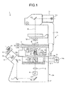
- FIG. 1 is a schematic view illustrating the entire structure of the microscope system according to the first embodiment.
- a microscope system 1 is an inverted microscope used for observing a specimen S specifically colored with, for example, a fluorescent pigment by focusing observation light from the specimen S, and includes a microscope main body 2 including a main body portion 2a as a foundation of the microscope system 1, a lens-barrel portion 2b detachably attached to the main body portion 2a and provided with at least an eyepiece, and a supporting column 2c extending from the main body portion 2a in a direction of an optical path N of the irradiation light to be delivered to the specimen S.
- the main body portion 2a includes a main body side base portion 21 having mirror legs 21a and 21b extending in approximately columnar shape to form a concave shape in a side view, and a holder 22 that has a concave shape, is supported by the mirror legs 21a and 21b, and holds a stage 3 and an objective lens 41, which are described below.
- the main body side base portion 21 may be provided with a control board that controls the entire microscope system 1.
- the control board may relay the power supplied from the outside to each unit, or may have a power source incorporated to relay the power to each unit.
- the main body side base portion 21 includes inside a tube lens 5 that forms an image by focusing the light taken in by the objective lens 41, an optical path changing prism 6 that transmits the light focused by the tube lens 5 and that bends the light in a specified direction, and mirrors 7a, 7b, and 7c that reflect the light transmitted through the optical path changing prism 6 in a specified direction.
- the optical path changing prism 6 may be provided so as to be able to be exchanged among a plurality of optical members with different transmittance, and may include any of an optical member (optical path changing prism 6) that transmits 50% of light and reflects 50% of light, an optical member that reflects all the light formed by the tube lens 5 in a specified direction, and an optical member that transmits all the light focused by the tube lens 5 so that the members can be exchanged freely on the optical path N.
- a camera port CP connected to a CCD camera or the like is provided at the position to which the optical path changing prism 6 reflects the light. The light bent by the optical path changing prism 6 in a direction orthogonal to the optical path N is introduced to the camera port CP.
- the lens-barrel portion 2b When the lens-barrel portion 2b is connected to the main body portion 2a, the observation light of the specimen S is introduced into the lens-barrel portion 2b from the main body side base portion 21.
- the lens-barrel portion 2b includes a tube lens 8 for focusing the observation light reflected from the mirror 7c, a prism 9 for bending the observation light focused by the tube lens 8 in a specified direction, and an eyepiece 10 for condensing the light bent by the prism 9.
- the eyepiece 10 is a lens for magnifying the formed intermediate image.
- the supporting column 2c is provided with a first lamp house 11 having a light source 11a and emitting transmission illumination light, and a condenser 12 supported to be able to move up and down along the optical path N of the objective lens 41.
- the first lamp house 11 is a case incorporating the light source 11a formed by a halogen lamp or the like, and is supported by the supporting column 2c. The light from the first lamp house 11 is reflected toward the specimen S (objective lens 41) by a mirror 11b.
- the holder 22 holds the stage 3 on which the specimen S is mounted at an end of the holder 22, and moreover holds a unit attachment portion 13 to which the objective lens unit 4 having the objective lens 41 for taking in at least the observation light from the specimen S on the stage 3 can be detachably attached in the hollow space with the concave shape.
- the main body side base portion 21 is provided with a second lamp house 14 having a light source 14a and emitting epi-illumination light.
- the second lamp house 14 is a case incorporating the light source 14a formed by a mercury lamp or the like, and is disposed detachably to the main body side base portion 21 through a floodlight tube 14b.
- the floodlight tube 14b can transmit the light emitted from the light source 14a of the second lamp house 14.
- the light source 14a may be replaced by a laser.
- An inner region 21c formed by the mirror legs 21a and 21b of the main body side base portion 21 is provided with a mirror unit 15 that changes the optical path of the epi-illumination light from the light source 14a, the light reflected from or emitted from the specimen S, or the light transmitted through the specimen S.
- the mirror unit 15 includes an excitation filter 15a, a dichroic mirror 15b, and an absorption filter 15c.
- the excitation filter 15a extracts (transmits) the light corresponding to the excitation wavelength from the emission light emitted from the light source 14a.
- the dichroic mirror 15b reflects the light with a specified wavelength from the light emitted from the light source 14a, and transmits the light with a specified wavelength from the light emitted from the specimen S.
- the absorption filter 15c extracts the light with a desired wavelength from the light emitted from the specimen S.
- the mirror unit 15 may be configured so that a plurality of, for example eight, mirror units is removably inserted into a mirror cassette in a manner that the mirror units 15 can advance or retract relative to the optical path of the light emitted from the light source 14a with a built-in motor (not shown).
- the stage 3 includes a mount unit 30 for having the specimen S mounted thereon, and a stage operation unit 31 for operating the position of the specimen S disposed on the mount unit 30.
- the mount unit 30 is formed by sequentially stacking a first member 30a, a second member 30b, and a third member 30c each having a plate shape.
- the first member 30a and the second member 30b are moved on a flat plane on the third member 30c with the third member 30c used as a reference (fixed) by the use of the stage operation unit 31.
- the specimen S is mounted on the first member 30a, and the first member 30a and the second member 30b move in directions orthogonal to each other on a plane parallel to the main plane.
- Each of the first member 30a to the third member 30c is provided with an aperture (not shown) through which the optical path N transmits when attached to the main body portion 2a.
- the apertures of the first member 30a and the second member 30b are formed with a size for including the optical path N regardless of the movement of the first member 30a and the second member 30b.
- the stage operation unit 31 includes input units 31a and 31b to which the travel amount of the first member 30a and the second member 30b can be input, and a support member 31c which supports the input units 31a and 31b and which sends the travel amount input through the input units 31a and 31b to the first member 30a and the second member 30b.
- the input units 31a and 31b are formed by, for example, the rack and pinion and through the input units 31a and 31b, the travel amount of the first member 30a and the second member 30b according to the amount of rotation is input.
- the first member 30a and the second member 30b may move automatically through the input bottom provided for the main body portion 2a or the like.
- the transmission illumination when the specimen S is irradiated with the transmission illumination light from the light source 11a through the mirror 11b, an intermediate image by the observation light having transmitted through the specimen S or the observation light emitted from the specimen S is formed on the observation optical path (optical path N) by the objective lens 41 and the tube lens 5, and the image is formed at the position of the eyepiece through the tube lens 8; thus, the image is observed visually by an observer as the specimen image by the transmission light.
- the transmission light observation is employed in the case of bright-field microscopy, phase contrast microscopy, differential interference contrast microscopy, or the like.
- the epi-illumination light from the light source 14a is collimated into a parallel light flux in the floodlight tube 14b, and the light with the excitation wavelength is selected by the excitation filter 15a from the light with the wavelengths included in the epi-illumination light, and then the light with the wavelength selected by the excitation filter 15a is reflected toward the objective lens 41 through the dichroic mirror 15b.
- the illumination light reflected from the dichroic mirror 15b is delivered to the specimen S through the objective lens 41 as the epi-illumination light, the fluorescent pigment or the fluorescent protein in the specimen S is excited and the fluorescent light is emitted.
- the generated fluorescent light is taken into the objective lens 41 as an image, and the light transmits through the dichroic mirror 15b and the absorption filter 15c; then, the intermediate image of the specimen S located on the optical path N is formed on the observation optical path by the objective lens 41 and the tube lens 5.
- the image is formed at the position of the eyepiece 10 through the tube lens 8 and visually observed by the observer as the specimen image by the emission of the fluorescent light or the like.
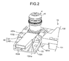
- FIG. 2 is a perspective view schematically illustrating the structure of a main part of the microscope system according to the first embodiment, in which the objective lens unit 4 is attached to the unit attachment portion 13.
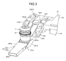
- FIG. 3 is a perspective view schematically illustrating the structure of the main part of the microscope system according to the first embodiment, in which the objective lens unit 4 is detached from the unit attachment portion 13.
- the objective lens unit 4 includes the objective lens 41 for taking in the observation light and a unit side base portion 42 (base portion) with an approximately belt shape holding the objective lens 41 on one end.
- the unit side base portion 42 includes an approximately-belt-shaped objective lens holder 421 for holding the objective lens 41 on one end, and a belt-shaped grip unit 422 extending from the other end of the objective lens holder 421.
- the grip unit 422 is a portion held by a user when the objective lens unit 4 is attached to the unit attachment portion 13.
- Each of side surfaces of the objective lens holder 421 that is orthogonal to the main plane and extends in parallel to the longitudinal direction is provided with a cut portion 421a (second engagement unit) which is a cut groove extending in the thickness direction.
- a side surface of the objective lens holder 421 that is orthogonal to the main plane and that is on the side opposite to the surface connecting to the grip unit 422 is provided with a slidable unit 421b that slides on the attachment surface (a guide groove to be described below) of the unit attachment portion 13 when attached to the unit attachment portion 13.
- the surface of the slidable unit 421b that slides on the attachment surface of the unit attachment portion 13 is tilted relative to the main plane of the objective lens holder 421.
- a side surface of the grip unit 422 that is orthogonal to the main plane and that is on the side opposite to the surface connecting to the objective lens holder 421 (on the other end side of the unit side base portion 42) is provided with a display unit 422a where the information of the objective lens 41 held by the unit side base portion 42 is displayed.
- the display unit 422a displays the information including at least the kind of the objective lens 41, the working distance (WD), and the magnification.
- the information of the kind of the immersion oil that can be used may be displayed.
- the information of the kind of the objective lens 41 includes the information related to the bright-field microscopy, the phase contrast microscopy, the differential interference contrast microscopy, and the fluorescence observation, and the correction level for the chromatic aberration.
- the color of the grip unit 422 may be different depending on the information of the objective lens 41.
- the unit attachment portion 13 includes a supporter 131 fixed to the holder 22, an intermediate portion 132 supported by the supporter 131 and extending in a direction orthogonal to the optical path N, and a unit holder 133 held by the intermediate portion 132 and detachably holding the objective lens unit 4.
- the intermediate portion 132 is provided with an aperture portion 1321 having an aperture with an approximately circular shape through which the optical path N transmits when attached to the holder 22.
- the unit holder 133 is held by the intermediate portion 132 and includes a tilt portion 1331 having a tilt surface, and a click mechanism 1332 (first engagement unit) provided on the tilt portion 1331 and engaged with the cut portion 421a of the objective lens unit 4 to control the movement of the objective lens unit 4.
- a click mechanism 1332 first engagement unit
- the tilt portion 1331 is disposed so that a plane passing along the tilt surface intersects with the optical path N, and extends obliquely downward on the main body portion 2a from the intermediate portion 132.
- the tilt portion 1331 is provided with a guide groove 1331a (guide unit) that guides the attachment direction of the objective lens holder 421 of the objective lens unit 4.
- the groove width (distance between the opposite side walls) of the guide groove 1331a is approximately equal to the maximum width of the objective lens holder 421.
- the depth (height of the side wall) of the guide groove 1331a is smaller than the plate thickness of the objective lens holder 421.
- the guide groove 1331a is provided with a concave portion 1331b that connects to the aperture portion 1321 and that forms a hollow space through which the illumination light and the observation light transmit when attached to the holder 22.
- the click mechanism 1332 is provided for each of edges of the tilt portion 1331 in the groove width direction of the guide groove 1331a.
- the click mechanism 1332 has a ball 1332a to be energized by a spring or the like.
- the ball 1332a is provided to protrude inward (toward the guide groove 1331a) relative to the plane passing along the side wall of the guide groove 1331a.
- the ball 1332a is provided to advance or retract freely in a direction approximately orthogonal to the plane passing along the side wall of the guide groove 1331a with the energizing force from the spring.
- the diameter of the ball 1332a of the click mechanism 1332 is preferably larger than the groove width of the cut portion 421a in the part that is exposed to the outside to be engaged with the cut portion 421a.
- the energizing force from the spring may be such a degree that when the cut portion 421a and the ball 1332a are engaged with each other and a load in a direction opposite to the attachment direction is applied by at least the own weight of the objective lens unit 4, the ball 1332a is not retracted.
- a dovetail groove constituting the hollow space with an approximately concave-shaped section is formed at the bottom of the guide groove 1331a and the slidable unit 421b has a projection that projects with a sectional shape according to the dovetail groove of the guide groove 1331a from the main plane.
- the projection may extend along the attachment direction of the objective lens unit 4 or be provided at the center of the attachment direction or be provided at each end in the attachment direction.
- the projection may be formed at any position or with any shape as long as the projection can be housed in the dovetail groove.
- FIG. 4 is a perspective view schematically illustrating a main part of the microscope system according to the first embodiment, and describing the attachment of the objective lens unit 4 to the unit attachment portion 13.
- a user grips the grip unit 422 and inserts the objective lens unit 4 to the unit attachment portion 13 (guide groove 1331a) from obliquely below the stage 3.
- the objective lens unit 4 is inserted while the slidable unit 421b is slid along the guide groove 1331a.
- the projection is housed in the dovetail groove of the guide groove 1331a. This can prevent the slidable unit 421b from moving deviated from the attachment direction the guide groove 1331a (slide direction, arrow in FIG. 4 ) when the objective lens unit 4 is attached to the unit attachment portion 13.
- the ball 1332a of the click mechanism 1332 is in pressure contact with the side surface of the objective lens holder 421.
- the cut portion 421a of the objective lens holder 421 is engaged with the ball 1332a of the click mechanism 1332.
- the objective lens 41 is disposed on the concave portion 1331b (see FIG. 2 ).
- the objective lens 41 when the objective lens 41 is held by the objective lens holder 421 so that the optical axis is orthogonal to the mount surface (main plane) of the objective lens holder 421, the sum of the angle between the optical path N and the bottom of the guide groove 1331a and the angle between the slide surface of the slidable unit 421b and the main plane of the objective lens holder 421 is 90°.
- the slidable unit 421b when the objective lens unit 4 is attached to the unit attachment portion 13, the slidable unit 421b is slid while the state where the main plane of the objective lens holder 421 is orthogonal to the optical path N is maintained, and the optical axis of the objective lens 41 can be moved while the optical axis is maintained to be parallel to the optical path N. Therefore, even when the immersion oil is on the upper surface of the objective lens 41, the objective lens 41 can be set without spilling the immersion oil.
- the objective lens unit 4 when the objective lens unit 4 is attached to the unit attachment portion 13, it is not always necessary to make the movement while maintaining the state that the optical axis of the objective lens 41 is parallel to the optical path N as long as the optical axis of the objective lens 41 coincides with the optical path N at the position where the cut portion 421a of the objective lens holder 421 is caught by the ball 1332a of the click mechanism 1332 and stopped thereby (at the position where the placement of the objective lens 41 is completed).
- the angle between the optical path N and the bottom of the guide groove 1331a except the position where the placement of the objective lens 41 is completed may be set to, for example, the angle according to the easiness of the insertion and removal between the objective lens unit 4 and the unit attachment portion 13.
- the side surface provided with the display unit 422a extends outward from the unit attachment portion 13 and is visible from the side surface of the main body portion 2a. Thus, the information of the objective lens 41 attached to the unit attachment portion 13 can be easily checked.
- the user pulls out the objective lens unit 4 in a direction opposite to the attachment direction while holding the grip unit 422, whereby the ball 1332a retracts to cancel the engaged state between the cut portion 421a and the ball 1332a.
- continuing to pull out the objective lens unit 4 can remove the objective lens unit 4 from the unit attachment portion 13, and thus the objective lens unit 4 can be replaced by the objective lens unit for holding another kind of objective lens.
- FIG. 5, FIG. 6 , and FIG. 9 to FIG. 15 are schematic views illustrating examples of other structures of the objective lens unit of the microscope system according to the first embodiment.
- the objective lens unit 4 may have a function of providing additional functions to the objective lens 41 in addition to holding the objective lenses 41 with different magnifications.
- the attachment unit that does not hold the objective lens 41 as illustrated in FIG. 7 and FIG. 8 may be attached to the unit attachment portion 13.
- FIG. 5 is a perspective view schematically illustrating an example of another structure of the objective lens unit of the microscope system according to the first embodiment.
- An objective lens unit 4a illustrated in FIG. 5 has a sheet-shaped heating member 43 provided for a part of the side surface of the objective lens 41.
- the heating member 43 is heated based on a control signal from an external controller, which is not shown, and maintains specified temperature. This enables the objective lens 41 to be maintained at a set temperature.
- the environment temperature needs to be maintained at approximately 37°C.
- the objective lens 41 is formed of a material with high heat efficiency, the heat dissipates to the outside through the objective lens 41, in which case the environment temperature around the specimen S may not be maintained at 37°C.
- the objective lens unit 4a can maintain the temperature of the objective lens 41 to be specified temperature; therefore, it is possible to prevent the heat dissipation through the objective lens 41 and to achieve the observation with the environment temperature maintained.
- FIG. 6 is a perspective view schematically illustrating an example of another structure of the objective lens unit of the microscope system according to the first embodiment.
- An objective lens unit 4b illustrated in FIG. 6 is provided with a supply tube 44 that supplies the immersion oil to the end of the objective lens 41.
- the immersion oil is fed to the supply tube 44 with an external liquid pumping mechanism such as a controller or a piston, which is not illustrated. This makes it possible to supply the immersion oil without retracting the stage 3 after the objective lens unit 4b is attached to the unit attachment portion 13, i.e., in the state that the objective lens 41 is disposed on the optical path N.
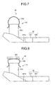
- FIG. 7 is a schematic diagram illustrating an example of the structure of the attachment unit of the microscope system according to the first embodiment.
- FIG. 8 is a schematic diagram describing an example of usage of the attachment unit of the microscope system according to the first embodiment.
- the unit side base portion 42 holds an oil removal unit 45 having an oil-absorbent paper holding member 45a for holding oil-absorbent paper 45b as a remover for removing the immersion oil instead of the objective lens 41.
- the oil-absorbent paper holding member 45a holds opposite ends of the oil-absorbent paper 45b having a band shape, for example, in the longitudinal direction.
- the oil-absorbent paper 45b has an approximately "U" shape projecting from the end of the oil-absorbent paper holding member 45a.
- the oil-absorbent paper holding member 45a holds the oil-absorbent paper 45b by using a known fixing unit such as adhesion or clipping.
- the oil-absorbent paper 45b may be any paper as long as the paper can absorb the liquid to be removed such as the immersion oil.
- the oil-absorbent paper 45b absorbs the immersion oil attached to a dish 100 holding the specimen and removes the immersion oil from the dish 100.
- the immersion oil can be easily removed from the dish 100 just by inserting and removing the attachment unit 40 into and from the unit attachment portion 13 once or several times without moving the dish 100. Therefore, the observation without the use of the immersion oil and the observation with the use of the immersion oil can be simply switched; additionally, the observation without the use of the immersion oil can be conducted without any influence from the immersion oil.
- the oil removal unit 45 may be provided at the end of the objective lens unit 4b in the attachment direction.
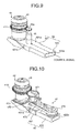
- FIG. 9 is a perspective view schematically illustrating an example of another structure of the objective lens unit of the microscope system according to the first embodiment.
- An objective lens unit 4c illustrated in FIG. 9 is provided with a motor 46 (driving source) for generating the power for rotating a correction collar 411 provided for the objective lens 41.
- the objective lens 41 is provided with the correction collar 411 with an uneven shape along the circumferential direction of the side surface of the objective lens 41.
- the correction collar 411 is rotatably provided and moves the lens group (optical system) provided inside the objective lens 41 in the direction of the optical axis with the rotation of the correction collar 411.
- the aberration spherical aberration
- a gear 46a is provided which meshes with the correction collar 411.
- the gear 46a is rotated by the rotation of the motor 46, and by transmitting the rotating power to the correction collar 411, rotates the correction collar 411.
- the motor 46 is, for example, a stepping motor. By using the stepping motor as the motor 46, the amount of rotation of the correction collar 411 can be decided by the number of given pulses; thus, the correction collar 411 can be rotated at high accuracy.
- the correction collar 411 and the motor 46 constitute the aberration correction unit.
- the motor 46 is driven based on a control signal from an external controller, which is not shown, and rotates the correction collar 411 through the gear 46a.
- FIG. 10 is a perspective view schematically illustrating an example of another structure of the objective lens unit of the microscope system according to the first embodiment.
- An objective lens unit 4d illustrated in FIG. 10 is provided with a power transmission mechanism 47 (driving source) for transmitting the power used for rotating a correction collar 412 provided for the objective lens 41.
- the power transmission mechanism 47 includes: a first gear 471 which meshes with the correction collar 412; a second gear 472 provided on the same central axis as the first gear 471; a shaft 473 connecting the first gear 471 and the second gear 472 and fixed rotatably to the objective lens holder 421; a third gear 474 rotatably provided for the grip unit 422; and a geared belt 475 which is formed by bonding opposite ends of a belt-shaped member and which meshes with the second gear 472 and the third gear 474 on the inner periphery.
- the rotation power of the third gear 474 is transmitted to the second gear 472 through the geared belt 475 when the user rotates the third gear 474.
- the second gear 472 is rotated, the first gear 471 fixed to the shaft 473 is rotated in conjunction.
- the correction collar 412 can be rotated.
- the correction collar 412 can be manually rotated by a user unlike in the objective lens unit 4c. Since the third gear 474 is provided on the grip unit 422, the operability is excellent.
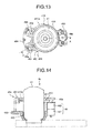
- FIG. 11 is a perspective view schematically illustrating an example of another structure of the objective lens unit of the microscope system according to the first embodiment.
- FIG. 12 is a perspective view schematically illustrating a structure of a main part of the objective lens unit illustrated in FIG. 11 .
- FIG. 13 is a top view schematically illustrating the structure of the main part of the objective lens unit illustrated in FIG. 11 .
- FIG. 14 is a partial sectional view taken along a line A-A of FIG. 13 .
- FIG. 15 is an exploded perspective view schematically illustrating the structure of the main part of the objective lens unit illustrated in FIG. 12 .
- the objective lens unit 4e illustrated in FIG. 11 includes a detection mechanism 48 for detecting the position at which the correction collar 411 is set.
- the detection mechanism 48 includes, as illustrated in FIG. 15 , a holding member 481 attached to the objective lens 41 and holding the motor 46 and detection sensors 49a and 49b (position detectors).
- the holding member 481 includes an objective lens attachment unit 482 through which the objective lens 41 is inserted and which is held by the objective lens 41, a motor holder 483 holding the motor 46, and a sensor holder 484 holding the detection sensors 49a and 49b.
- the objective lens attachment unit 482 is provided with a hole 485 through which the objective lens 41 can be inserted.
- the correction collar 411, the motor 46, the detection sensors 49a and 49b, and the holding member 481 constitute the aberration correction unit.
- the objective lens 41 is provided with, in addition to the correction collar 411, a detection wing 413 (position detector) which is provided below the correction collar 411 and which is to be detected by the detection sensors 49a and 49b.
- the detection wing 413 has a cut shape formed by circumferentially cutting a part of a light-blocking member with a hollow circular plate shape on the outer peripheral side.
- the detection wing 413 has a projection 413a formed by the cut shape and having a part of the outer periphery projecting radially.
- Each of the detection sensors 49a and 49b is formed by, for example, a photo-interrupter.
- the detection sensors 49a and 49b respectively have detection units 491 and 492 constituting a light emission unit and a light reception unit, and the projection 413a is disposed through and between the light emission unit and the light reception unit of the detection units 491 and 492.
- the light reception mode of the detection sensors 49a and 49b changes depending on whether the projection 413a has passed or not. This enables to detect the set position on the correction collar 411 depending on the change of the light reception mode.
- the detection signal upon the detection of the projection 413a by the detection sensors 49a and 49b, the detection signal is turned off and if the projection 413a is not detected, the detection signal is turned on.
- the position of the reference position relative to the detection sensors 49a and 49b can be detected by determining whether the detection signals of the two detection sensors 49a and 49b are on or off. In the case of moving the reference position to a specified position according to the detection result, it is possible to determine which direction is more appropriate to rotate the correction collar 411, clockwise or counterclockwise.
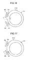
- FIG. 16 and FIG. 17 are diagrams for describing the rotation control of the correction collar of the objective lens unit illustrated in FIG. 11 .
- the control signal related to the driving of the motor 46 or the position detection based on the detection result of the detection sensors 49a and 49b is output from a control unit provided for a specified signal line, the holding member 481, the unit side base portion 42, the main body side base portion 21, or the like.
- the control unit first determines whether the detection signals of the two detection sensors 49a and 49b are on or off and detects the reference position P relative to the detection sensors 49a and 49b.
- the control unit determines that the reference position P is between the detection sensor 49a and the detection sensor 49b (see FIG. 16 ). After that, the control unit rotates the correction collar 411 counterclockwise until the detection signal of the detection sensor 49a is changed from on to off (see FIG. 17 ).
- the control unit By knowing the position of the correction collar 411 using the two detection sensors (detection sensors 49a and 49b) and the detection wing 413, the time needed to align the reference position P to the specified position can be shortened as compared to the conventional method of detecting the position of the correction collar 411 by rotating the correction collar once. Further, the optimum position adjustment of the correction collar 411 becomes possible and the favorable observation image can be obtained.
- the control unit functions as a part of the aberration correction unit.
- the holding member 481 is detachably provided for the objective lens 41 and the unit side base portion 42, the same holding member 481 can be used even after the objective lens 41 is exchanged.
- the objective lens 41 is inserted through the hole 485, by enabling the motor holder 483 to move (or rotate) in a direction apart from the objective lens attachment unit 482, the objective lens 41 can be more easily inserted because the interference between the objective lens 41 and the motor holder 483 (gear 46a) or the sensor holder 484 (detection units 491 and 492) is prevented.
- the motor holder 483 is rotated, the motor holder 483 moves away from the objective lens attachment unit 482 if the rotation shaft of the motor 46 is tilted relative to the center axis of the hole 485. If the motor holder 483 is left tilted, the correction collar 411 can even be rotated manually.
- the motor 46 preferably includes a stepping motor 461 and a decelerator 462 as illustrated in FIG. 14 because the stationary stability is high and the amount of rotation of the correction collar 411 can be controlled with high accuracy.
- the electric power may be supplied to the motor 46 or the detection sensors 49a and 49b through a specified signal line or through a connector provided for the unit side base portion 42 or the like.
- the objective lens unit 4 holding the objective lens 41 is attached from obliquely below the stage 3 in a manner that the objective lens unit 4 can be freely inserted or removed, the objective lens can be easily detached.
- the desired objective lens can be disposed without changing the position of the specimen S held on the stage 3, and the specimen S can be observed easily and certainly.
- the objective lens unit can be selectively inserted or removed and the objective lens unit with the function added can be attached; therefore, the desired objective lens can be disposed easily regardless of the function of the objective lens.
- the top (on the side to be provided with the objective lens) of the revolver is covered by the stage; therefore, it is difficult to exchange the objective lens relative to the revolver as compared to the upright microscope.
- the microscope system according to the first embodiment it is possible to easily exchange the objective lens (objective lens unit) without retracting the stage 3.
- the incubator having a function of maintaining the temperature is disposed on the stage, in which case the objective lens cannot be exchanged and the supply of the immersion oil is impossible.
- the immersion oil can be supplied without removing the incubator from the stage 3 and without moving the specimen S.
- FIG. 18 is a top view schematically illustrating the structure of the main part of the microscope system according to the modified example of the first embodiment.
- the above objective lens unit 4 and the unit attachment portion 13 are provided with an electric connection unit that enables the electric connection.
- the objective lens unit 4 illustrated in FIG. 18 the objective lens holder 421 is provided with a conductive pin 421d.
- the unit attachment portion 13 is provided with a connection unit 1322 having a housing unit 1322a that can electrically be connected to the pin 421d when the objective lens unit 4 is attached. To the connection unit 1322, the electric power is supplied through the main body side base portion 21 or the like.
- the pin 421d is housed in the housing unit 1322a and the objective lens unit 4 is electrically connected to the unit attachment portion 13.
- the electric power required to drive the objective lens units 4a, 4c, 4d, 4e, etc. can be supplied from the unit attachment portion 13 to the objective lens unit 4.
- the arrangement of the pin 421d and the housing unit 1322a is not limited thereto as long as the electric connection is possible; the pin 421d and the housing unit 1322a may be oppositely disposed or may be arranged to be electrically connected to each other wirelessly or by other known connection techniques.
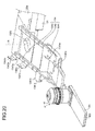
- FIG. 19 is a perspective view schematically illustrating a structure of a main part of a microscope system according to a second embodiment of the present invention, in which an objective lens unit 4f is attached to a unit attachment portion 13a.
- FIG. 20 is a perspective view schematically illustrating the structure of the main part of the microscope system according to the second embodiment of the present invention, in which the objective lens unit 4f is detached from the unit attachment portion 13a.
- the same components as those of FIG. 1 , etc. are denoted by the same reference signs.
- the microscope system according to the second embodiment includes the objective lens unit 4f and the unit attachment portion 13a instead of the objective lens unit 4 and the unit attachment portion 13 in the first embodiment.
- the objective lens unit 4f includes the objective lens 41, and a unit side base portion 42a (base portion) with an approximately belt shape for holding the objective lens 41 on one end.
- the unit side base portion 42a holds the objective lens 41 on one end and the other end thereof is held by the user when the objective lens unit 4f is attached to the unit attachment portion 13a.
- a side surface of the unit side base portion 42a that intersects with the longitudinal direction and that is opposite to the side at which the objective lens 41 is held is provided with a display unit 423 which displays the information related to the objective lens 41 held by the unit side base portion 42a.
- the display unit 423 displays the information including at least the kind of the objective lens 41, the working distance (WD), and the magnification.
- the information including the kind of the immersion oil that can be used may be displayed.
- the information of the kind of the objective lens 41 includes the information related to the bright-field microscopy, the phase contrast microscopy, the differential interference contrast microscopy, the fluorescence observation, and the like, and the correction level for the chromatic aberration.
- the color of the other end side of the unit side base portion 42a may be different depending on the information of the objective lens 41.
- the unit attachment portion 13a includes the aforementioned supporter 131, an intermediate portion 132a supported by the supporter 131 and extending in a direction intersecting with the optical path N, and a unit holder 134 held by the intermediate portion 132a, detachably holding the objective lens unit 4f, and inserting the objective lens unit 4f onto the optical path N and retracting the objective lens unit 4f from the optical path N.
- the intermediate portion 132a is provided with an aperture portion 1323 having an aperture with an approximately circular shape through which the optical path N transmits when attached to the holder 22.
- the unit holder 134 includes: a holder 1341 for holding detachably the objective lens unit 4f; an extension portion 1342 supported on the supporter 131 side of the intermediate portion 132a and extending in the approximately prism shape oblique to the optical path N; and an extension portion 1343 supported on the side opposite to the aperture portion 1323 relative to the extension portion 1342 and extending in the approximately prism shape in parallel to and at the same tilt angle as the extension portion 1342.
- the extension portions 1342 and 1343 extend obliquely downward from the intermediate portion 132a, and functions as a guiding portion that guides the attachment direction of the unit side base portion 42a.
- the holder 1341 is disposed on the extension portions 1342 and 1343, and can move along the longitudinal direction of the extension portions 1342 and 1343.
- the holder 1341 includes a housing unit 1341a that can house the unit side base portion 42a of the objective lens unit 4f so that the unit side base portion 42a can be freely inserted into or removed from the housing unit 1341a, and a control member 1341b for controlling the position where the holder 1341 is stopped on the extension portions 1342 and 1343.
- the housing unit 1341a is provided with an aperture portion 1341c forming an aperture through which the illumination light or the observation light passes.
- the extension portion 1342 is provided with a plurality of balls 1342a formed by projecting parts of the top surface of the extension portion 1342 and disposed rotatably in the longitudinal direction of the extension portion 1342.
- the extension portion 1343 is provided with a plurality of balls 1343a formed by projecting parts of the top surface of the extension portion 1343 and disposed rotatably in the longitudinal direction of the extension portion 1343, and three engagement members (first engagement member 1343b, second engagement member 1343c, and third engagement member 1343d) with a flat plate shape that engage with the control member 1341b and have a main plane bent to have an L shape in side view.
- the three engagement members (first engagement member) include a bottom portion constituting a bottom part of L and a vertical portion constituting a vertical part of L.
- the holder 1341 is attached so that the holder 1341 is not detached from the extension portions 1342 and 1343, and is supported by the balls 1342a and 1343a and can be smoothly moved by the rotation of the balls 1342a and 1343a.
- the holder 1341 has claws that are hooked by the bottoms of the extension portions 1342 and 1343, and by slidably having the claws hooked in the bottoms of the extension portions 1342 and 1343, the detachment of the holder 1341 from the extension portions 1342 and 1343 can be prevented in the state that the extension portions 1342 and 1343 can be freely moved in the longitudinal direction of the extension portions 1342 and 1343.
- the first engagement member 1343b, the second engagement member 1343c, and the third engagement member 1343d are provided along the longitudinal direction of the extension portion 1343, and the bottoms thereof are supported so that the vertical portions thereof come to the side opposite to the extension portion 1342 relative to the extension portion 1343.
- An end of the first engagement member 1343b is provided with a projection 1343e projecting toward the extension portion 1343.
- the second engagement member 1343c and the third engagement member 1343d are similarly provided with the projection 1343e.
- control member 1341b is provided at a side end of the housing unit 1341a, and is located on the extension portion 1343 when the holder 1341 is inserted through the extension portions 1342 and 1343 to be able to be in contact with the projection 1343e of the engagement member.
- a surface of the control member 1341b that faces the vertical portion of the engagement member is provided with a cut portion 1341d (second engagement unit) with a cut shape that can be engaged with the projection 1343e.
- the first engagement member 1343b, the second engagement member 1343c, and the third engagement member 1343d are disposed so that the position where the projection 1343e is hooked by the cut portion 1341d of the control member 1341b comes to the specified position.
- the first engagement member 1343b is disposed at the position where the optical axis of the objective lens 41 coincides with the optical path N
- the second engagement member 1343c is disposed at the position where the objective lens 41 does not interfere with the optical path N and the distance from the optical path N is the shortest
- the third engagement member 1343d is disposed at the position where the objective lens 41 is disposed at an end of the extension portion 1343.
- the user When the objective lens unit 4f is attached to the unit attachment portion 13a and the objective lens 41 is disposed on the optical path N, the user first houses the unit side base portion 42a in the housing unit 1341a. On this occasion, the user holds the objective lens unit 4f while gripping the end of the unit side base portion 42a and inserts the objective lens unit 4f into the housing unit 1341a of the unit attachment portion 13a.
- a click mechanism may be provided at the completion position so as to prevent the detachment of the objective lens unit 4f from the housing unit 1341a.
- the optical axis of the objective lens 41 is preferably in parallel to the optical path N.
- the holder 1341 moves along the extension portions 1342 and 1343.
- the holder 1341 can move smoothly owing to the rotation of the balls 1342a and 1343a provided for the extension portions 1342 and 1343.
- the objective lens unit 4f is inserted into the optical path N from obliquely below the stage 3.
- the engagement occurs in the order of the third engagement member 1343d, the second engagement member 1343c, and the first engagement member 1343b, and the optical axis of the objective lens 41 coincides with the optical path N at the position where the projection 1343e of the first engagement member 1343b is engaged and stopped.
- the display unit 423 can be visually observed from outside.
- the information of the objective lens 41 attached to the unit attachment portion 13a can be easily checked.
- the holder 1341 is pulled out in a direction opposite to the attachment direction to cancel the engaged state between the cut portion 1341d and the projection 1343e. After that, continuing the pulling out can take out the holder 1341 to the position where the holder 1341 is engaged with the third engagement member 1343d. After that, the objective lens unit 4f can be replaced by the objective lens unit holding another kind of objective lens.
- the objective lens unit 4f holding the objective lens 41 is detachably attached to the holder 1341 from obliquely below the stage 3; therefore, the objective lens can be easily attached to or detached from the microscope main body.
- the objective lens unit 4f is housed in the holder 1341 and the objective lens 41 is disposed on the optical path N by moving the holder 1341; thus, the structure of the objective lens unit 4f can be made simple.
- the objective lens unit 4f according to the second embodiment can have a mechanism of adding the functions of FIG. 5 to FIG. 11 .
- the objective lens unit is attached to the unit holder from one direction; alternatively, the objective lens unit may be attached to the unit holder from a plurality of directions. In this case, by providing a second tilt portion on the side opposite to the tilt portion 1331, the objective lens unit 4 can be attached from the opposite direction.
- a plurality of click mechanisms may be provided at the positions of the engagement members described in the second embodiment.
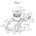
- FIG. 21 is a perspective view schematically illustrating a structure of a main part of a microscope system according to a third embodiment of the present invention, in which the objective lens unit 4 is attached to a unit attachment portion 13b.
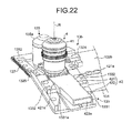
- FIG. 22 is a perspective view schematically illustrating the structure of the main part of the microscope system according to the third embodiment of the present invention, in which the objective lens unit 4 is attached to the unit attachment portion 13b and which is viewed from the direction opposite to that of FIG. 21 .
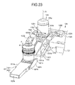
- FIG. 23 is a perspective view schematically illustrating the structure of the main part of the microscope system according to the third embodiment, in which the objective lens unit 4 is detached from the unit attachment portion 13b.
- the microscope system according to the third embodiment includes a unit attachment portion 13b instead of the unit attachment portion 13 according to the first embodiment.
- the unit attachment portion 13b includes: the supporter 131 fixed to the holder 22; an intermediate portion 132b supported by the supporter 131; the unit holder 133 that is held by the intermediate portion 132b and detachably holds the objective lens unit 4; an objective lens holder 135 that is held by the intermediate portion 132b and holds an objective lens 135a (second objective lens) such that the objective lens 135a can freely advance or retract relative to the optical path N; and energizing members 136 and 137 that energize the objective lens holder 135 in a direction intersecting with the optical path N.
- the intermediate portion 132b has the aperture portion 1321 having an aperture with an approximately circular shape through which the optical path N passes when attached to the holder 22.
- the intermediate portion 132b includes: a support member 1324 that is provided adjacent to the holder part of the unit holder 133 on the supporter 131 side, supporting the energizing member 136, and restricting the movement of the objective lens holder 135; and a support member 1325 provided on the side surface near the aperture portion 1321, which is on the side opposite to the supporter 131, and supporting the energizing member 137.
- the objective lens holder 135 includes: the objective lens 135a with a specified magnification; a holder 135b holding the objective lens 135a and movably provided in the direction where the lens is attached or detached relative to the optical path N; and a contact unit 135c brought into contact with the objective lens unit 4 by the insertion of the objective lens unit 4.
- the contact unit 135c has a contact member 1351 with an approximately rod shape.
- the contact member 1351 extends in a direction parallel to the optical path N, and has a part advancing into the aperture portion 1321.
- the objective lens 135a for example, an objective lens with lower magnification than the objective lens 41 attached to the objective lens unit 4 is used.
- the holder 135b is provided on the side opposite to the contact unit 135c relative to the objective lens 135a and includes a belt-shaped member 1352 with an approximately belt shape.
- the belt-shaped member 1352 is disposed with the longitudinal direction thereof orthogonal to the direction where the holder 135b moves.
- the length of the belt-shaped member 1352 in the longitudinal direction is approximately the same as the width of the unit holder 133.
- the energizing member 136 connects the support member 1324 provided for the intermediate portion 132b, and one end of the belt-shaped member 1352 (end on the supporter 131 side).
- the energizing member 137 connects the support member 1325 provided for the intermediate portion 132b and the other end of the belt-shaped member 1352.
- the energizing members 136 and 137 have the minimum energizing force when the objective lens 135a is disposed on the optical path N, and have larger energizing force as the objective lens 135a is set apart from the optical path N. In other words, the energizing members 136 and 137 energize the objective lens holder 135 in a direction toward the optical path N, which is the direction intersecting with the optical path N.
- the energizing members 136 and 137 are formed using, for example, a coil spring.
- the slidable unit 421b is slid along the guide groove 1331a to be inserted in a manner similar to the first embodiment. Note that in the state that the objective lens unit 4 is not inserted onto the optical path N, the holder 135b is in contact with the support member 1324 and the objective lens 135a is disposed on the optical path N.
- the contact member 1351 is brought into contact with a contact surface 421c of the objective lens holder 421. After that, continuing the insertion of the objective lens unit 4 makes the objective lens unit 4 press the contact member 1351, whereby the objective lens holder 135 moves to retract from the optical path N. Thus, the objective lens 135a retracts from the optical path N.
- the user pulls out the objective lens unit 4 in a direction opposite to the attachment direction while gripping the grip unit 422, thereby cancelling the engaged state between the cut portion 421a and the ball 1332a.
- continuing the pulling out can remove the objective lens unit 4 from the unit attachment portion 13b and the objective lens unit 4 can be replaced by the objective lens unit holding another kind of objective lens.
- the energizing force from the energizing members 136 and 137 the holder 135b moves toward the optical path N following the movement of the objective lens unit 4, and upon the contact with the support member 1324, the objective lens 135a comes on the optical path N again.
- the objective lens unit 4 holding the objective lens 41 is detachably attached from obliquely below the stage 3 in a manner similar to the first embodiment; therefore, the objective lens can be easily attached to or detached from the microscope main body.
- the objective lens 135a with different magnification from the objective lens 41 is disposed so that the objective lens 135a can advance or retract freely relative to the optical path N and the objective lens to be disposed on the optical path N can be replaced by the insertion of the objective lens unit 4; thus, by disposing the frequently used objective lens in advance, the objective lens can be replaced just by the insertion or removal of the objective lens unit 4. Accordingly, the specimen can be observed with higher efficiency.
- the incubator with a function of maintaining the temperature constant may be disposed on the stage 3.
- the portion of the specimen S to be observed is found using the low-magnification objective lens that enables the observation of a wide field and then the detailed observation is made with the high-magnification objective lens to which the immersion oil is supplied.
- the presence of the incubator interrupts the oil supply.
- the observation at the low magnification to the high magnification can be smoothly conducted by disposing the high-magnification objective lens to which the immersion oil is supplied on the optical path N after the observation with the low-magnification objective lens.
- the contact surface 421c of the objective lens holder 421 may have a cut shape according to the shape of the contact member 1351. This makes more certain the slidable contact between the contact surface 421c and the contact member 1351.
- the objective lens holder 135 according to the third embodiment can be applied to the structure of the second embodiment.
- the intermediate portion 132a is replaced by the intermediate portion 132b, and the energizing members 136 and 137 are attached.
- the aforementioned oil removal unit 45 may be disposed instead of the objective lens holder 135 according to the third embodiment.
- the oil removal unit 45 is disposed on the optical path N and the immersion oil can be automatically removed from the dish 100 when the objective lens unit 4 is detached.
- the stage 3 may be able to move up and down along the direction of the optical path N, or the supporter 131 may be provided with a driving mechanism to enable the up and down movement of the intermediate portions 132, 132a, and 132b along the optical path N.
- the first to third embodiments have described the inverted microscope system; however, the present invention can be applied also to an upright microscope system.
- the dovetail groove formed in the guide groove 1331a and the convex portion formed in the slidable unit 421b of the objective lens unit 4 are fitted to each other to prevent the drop due to the gravity.
- the first to third embodiments above are just the examples of the present invention and the present invention is not limited thereto.
- Various inventions can be accomplished by combining a plurality of components disclosed in the embodiments or modified example as appropriate.
- the present invention can be variously modified according to the specification, etc. and it is apparent that various embodiments can be applied within the scope of the present invention.
Landscapes
- Physics & Mathematics (AREA)
- General Physics & Mathematics (AREA)
- Optics & Photonics (AREA)
- Chemical & Material Sciences (AREA)
- Analytical Chemistry (AREA)
- Microscoopes, Condenser (AREA)
- Lens Barrels (AREA)
- Lenses (AREA)
Abstract
Description
- The disclosure relates to a microscope system, an objective lens unit, and a microscope main body used for observing a specimen image by irradiating the specimen with irradiation light and receiving light that is reflected from the specimen or that is generated from the specimen.
- In the medical and biological fields, microscopes for observing specimens such as cells by irradiating the specimens with light have been conventionally used. Moreover, in the industrial fields, microscopes have been used in various purposes including the quality control of metal tissues, research and development of new materials, inspections of electronic devices and magnetic heads, etc. As the observation of the specimen through the microscope, in addition to the visual observation with the use of an eyepiece or the like, such observation has been known that the specimen is photographed using an imaging element such as a CCD or a CMOS image sensor and the photographed image is displayed on a monitor.
- As disclosed in Japanese Patent Application Laid-Open Publication No.
2007-286440 3690834 - In the conventional microscope, the specimen image can be observed at the desired magnification by disposing the desired objective lens on the optical axis of the observation light and the irradiation light while the revolver is rotated. In recent years, moreover, the kinds of the objective lens vary widely for enabling the observation of various specimens.
- However, there is the limitation on the number of objective lenses that can be held by the conventional revolver as disclosed in Japanese Patent Application Laid-Open Publication No.
2007-286440 3690834 - The objective lens is attached to the revolver generally by being inserted into the revolver with the use of a screw and the user's exchange of the objective lens is not assumed; thus, it has been difficult for the user to exchange the objective lens attached to the revolver. For this reason, the microscope has been required in which the objective lens can be easily attached to and detached from the microscope main body.
- The present invention has been made in view of the above, and an object of the invention is to provide a microscope system, an objective lens unit, and a microscope main body where an objective lens can be easily attached and detached.
- In accordance with some embodiments, a microscope system, an objective lens unit, and a microscope main body are presented.
- In some embodiments, a microscope system includes: a main body portion having an optical system for forming an image from at least observation light from a specimen; an objective lens unit having an objective lens for taking in the observation light and having a base portion with an approximately belt shape for holding the objective lens on one end; and a unit attachment portion that is held by the main body portion and is configured to detachably attach the base portion at a position where at least an optical axis of the objective lens coincides with an optical path of the observation light.
- In some embodiments, an objective lens unit is used for a microscope system including: a main body portion having an optical system for forming an image from at least observation light from a specimen; and a unit attachment portion that is held by the main body portion. The objective lens unit includes: an objective lens for taking in the observation light; and a base portion that has an approximately belt shape for holding the objective lens on one end, and is configured to be detachably attached to the unit attachment portion at a position where at least an optical axis of the objective lens coincides with an optical path of the observation light.
- In some embodiments, a microscope main body is used for a microscope system for focusing observation light from a specimen. The microscope main body includes: an optical system for forming an image from at least the observation light; and a unit attachment portion configured to attach a base portion of an objective lens unit having an objective lens for taking in the observation light and having the base portion with an approximately belt shape for holding the objective lens on one end, at a position where an optical axis of the objective lens coincides with an optical path of the observation light.
- The above and other features, advantages and technical and industrial significance of this invention will be better understood by reading the following detailed description of presently preferred embodiments of the invention, when considered in connection with the accompanying drawings.
-
-
FIG. 1 is a schematic view illustrating an entire structure of a microscope system according to a first embodiment of the present invention; -
FIG. 2 is a perspective view schematically illustrating a structure of a main part of the microscope system according to the first embodiment of the present invention; -
FIG. 3 is a perspective view schematically illustrating the structure of the main part of the microscope system according to the first embodiment of the present invention; -
FIG. 4 is a perspective view schematically illustrating the structure of the main part of the microscope system according to the first embodiment of the present invention; -
FIG. 5 is a perspective view schematically illustrating an example of another structure of an objective lens unit of the microscope system according to the first embodiment of the present invention; -
FIG. 6 is a perspective view schematically illustrating an example of another structure of an objective lens unit of the microscope system according to the first embodiment of the present invention; -
FIG. 7 is a schematic view illustrating an example of a structure of an attachment unit of the microscope system according to the first embodiment of the present invention; -
FIG. 8 is a schematic view illustrating an example of usage of the attachment unit of the microscope system according to the first embodiment of the present invention; -
FIG. 9 is a perspective view schematically illustrating an example of another structure of the objective lens unit of the microscope system according to the first embodiment of the present invention; -
FIG. 10 is a perspective view schematically illustrating an example of another structure of the objective lens unit of the microscope system according to the first embodiment of the present invention; -
FIG. 11 is a perspective view schematically illustrating an example of another structure of the objective lens unit of the microscope system according to the first embodiment of the present invention; -
FIG. 12 is a perspective view schematically illustrating a structure of a main part of the objective lens unit illustrated inFIG. 11 ; -
FIG. 13 is a top view schematically illustrating the structure of the main part of the objective lens unit illustrated inFIG. 11 ; -
FIG. 14 is a partial sectional view taken along a line A-A ofFIG. 13 ; -
FIG. 15 is an exploded perspective view schematically illustrating a structure of a main part of the objective lens unit illustrated inFIG. 12 ; -
FIG. 16 is a diagram for describing the rotation control of a correction collar of the objective lens unit illustrated inFIG. 11 ; -
FIG. 17 is a diagram for describing the rotation control of the correction collar of the objective lens unit illustrated inFIG. 11 ; -
FIG. 18 is a top view schematically illustrating a structure of a main part of a microscope system according to a modified example of the first embodiment of the present invention; -
FIG. 19 is a perspective view schematically illustrating a structure of a main part of a microscope system according to a second embodiment of the present invention; -
FIG. 20 is a perspective view schematically illustrating the structure of the main part of the microscope system according to the second embodiment of the present invention; -
FIG. 21 is a perspective view schematically illustrating a structure of a main part of a microscope system according to a third embodiment of the present invention; -
FIG. 22 is a perspective view schematically illustrating the structure of the main part of the microscope system according to the third embodiment of the present invention; -
FIG. 23 is a perspective view schematically illustrating the structure of the main part of the microscope system according to the third embodiment of the present invention; and -
FIG. 24 is a perspective view schematically illustrating the structure of the main part of the microscope system according to the third embodiment of the present invention. - Modes for carrying out the invention will be described below with reference to the attached drawings. The invention is not limited to the embodiments below. In each drawing used in the description below, the shape, the size, and the positional relation are schematically shown to such a degree that the content of the present invention can be understood. In other words, the present invention is not limited to the shape, the size, and the positional relation illustrated in each drawing only.
- First, an inverted microscope system according to a first embodiment of the present invention will be described with reference to the drawings.
FIG. 1 is a schematic view illustrating the entire structure of the microscope system according to the first embodiment. As illustrated inFIG. 1 , a microscope system 1 is an inverted microscope used for observing a specimen S specifically colored with, for example, a fluorescent pigment by focusing observation light from the specimen S, and includes a microscopemain body 2 including amain body portion 2a as a foundation of the microscope system 1, a lens-barrel portion 2b detachably attached to themain body portion 2a and provided with at least an eyepiece, and a supportingcolumn 2c extending from themain body portion 2a in a direction of an optical path N of the irradiation light to be delivered to the specimen S. - The
main body portion 2a includes a main bodyside base portion 21 havingmirror legs holder 22 that has a concave shape, is supported by themirror legs objective lens 41, which are described below. The main bodyside base portion 21 may be provided with a control board that controls the entire microscope system 1. The control board may relay the power supplied from the outside to each unit, or may have a power source incorporated to relay the power to each unit. - The main body
side base portion 21 includes inside atube lens 5 that forms an image by focusing the light taken in by theobjective lens 41, an optical path changing prism 6 that transmits the light focused by thetube lens 5 and that bends the light in a specified direction, andmirrors - The optical path changing prism 6 may be provided so as to be able to be exchanged among a plurality of optical members with different transmittance, and may include any of an optical member (optical path changing prism 6) that transmits 50% of light and reflects 50% of light, an optical member that reflects all the light formed by the
tube lens 5 in a specified direction, and an optical member that transmits all the light focused by thetube lens 5 so that the members can be exchanged freely on the optical path N. At the position to which the optical path changing prism 6 reflects the light, a camera port CP connected to a CCD camera or the like is provided. The light bent by the optical path changing prism 6 in a direction orthogonal to the optical path N is introduced to the camera port CP. - When the lens-
barrel portion 2b is connected to themain body portion 2a, the observation light of the specimen S is introduced into the lens-barrel portion 2b from the main bodyside base portion 21. The lens-barrel portion 2b includes atube lens 8 for focusing the observation light reflected from themirror 7c, a prism 9 for bending the observation light focused by thetube lens 8 in a specified direction, and aneyepiece 10 for condensing the light bent by the prism 9. Theeyepiece 10 is a lens for magnifying the formed intermediate image. - The supporting
column 2c is provided with afirst lamp house 11 having alight source 11a and emitting transmission illumination light, and acondenser 12 supported to be able to move up and down along the optical path N of theobjective lens 41. Thefirst lamp house 11 is a case incorporating thelight source 11a formed by a halogen lamp or the like, and is supported by the supportingcolumn 2c. The light from thefirst lamp house 11 is reflected toward the specimen S (objective lens 41) by amirror 11b. - The
holder 22 holds the stage 3 on which the specimen S is mounted at an end of theholder 22, and moreover holds aunit attachment portion 13 to which theobjective lens unit 4 having theobjective lens 41 for taking in at least the observation light from the specimen S on the stage 3 can be detachably attached in the hollow space with the concave shape. - The main body
side base portion 21 is provided with asecond lamp house 14 having alight source 14a and emitting epi-illumination light. Thesecond lamp house 14 is a case incorporating thelight source 14a formed by a mercury lamp or the like, and is disposed detachably to the main bodyside base portion 21 through afloodlight tube 14b. Thefloodlight tube 14b can transmit the light emitted from thelight source 14a of thesecond lamp house 14. Note that thelight source 14a may be replaced by a laser. - An
inner region 21c formed by themirror legs side base portion 21 is provided with amirror unit 15 that changes the optical path of the epi-illumination light from thelight source 14a, the light reflected from or emitted from the specimen S, or the light transmitted through the specimen S. - The
mirror unit 15 includes anexcitation filter 15a, adichroic mirror 15b, and anabsorption filter 15c. Theexcitation filter 15a extracts (transmits) the light corresponding to the excitation wavelength from the emission light emitted from thelight source 14a. Thedichroic mirror 15b reflects the light with a specified wavelength from the light emitted from thelight source 14a, and transmits the light with a specified wavelength from the light emitted from the specimen S. Theabsorption filter 15c extracts the light with a desired wavelength from the light emitted from the specimen S. Themirror unit 15 may be configured so that a plurality of, for example eight, mirror units is removably inserted into a mirror cassette in a manner that themirror units 15 can advance or retract relative to the optical path of the light emitted from thelight source 14a with a built-in motor (not shown). - The stage 3 includes a
mount unit 30 for having the specimen S mounted thereon, and astage operation unit 31 for operating the position of the specimen S disposed on themount unit 30. Themount unit 30 is formed by sequentially stacking afirst member 30a, asecond member 30b, and athird member 30c each having a plate shape. In themount unit 30, for example, thefirst member 30a and thesecond member 30b are moved on a flat plane on thethird member 30c with thethird member 30c used as a reference (fixed) by the use of thestage operation unit 31. On this occasion, the specimen S is mounted on thefirst member 30a, and thefirst member 30a and thesecond member 30b move in directions orthogonal to each other on a plane parallel to the main plane. Each of thefirst member 30a to thethird member 30c is provided with an aperture (not shown) through which the optical path N transmits when attached to themain body portion 2a. Note that the apertures of thefirst member 30a and thesecond member 30b are formed with a size for including the optical path N regardless of the movement of thefirst member 30a and thesecond member 30b. - The
stage operation unit 31 includesinput units first member 30a and thesecond member 30b can be input, and a support member 31c which supports theinput units input units first member 30a and thesecond member 30b. In the first embodiment, theinput units input units first member 30a and thesecond member 30b according to the amount of rotation is input. Thefirst member 30a and thesecond member 30b may move automatically through the input bottom provided for themain body portion 2a or the like. - In the microscope system 1 with the above structure, in the case of the transmission illumination, when the specimen S is irradiated with the transmission illumination light from the
light source 11a through themirror 11b, an intermediate image by the observation light having transmitted through the specimen S or the observation light emitted from the specimen S is formed on the observation optical path (optical path N) by theobjective lens 41 and thetube lens 5, and the image is formed at the position of the eyepiece through thetube lens 8; thus, the image is observed visually by an observer as the specimen image by the transmission light. Note that the transmission light observation is employed in the case of bright-field microscopy, phase contrast microscopy, differential interference contrast microscopy, or the like. - In the case of the epi-illumination, the epi-illumination light from the
light source 14a is collimated into a parallel light flux in thefloodlight tube 14b, and the light with the excitation wavelength is selected by theexcitation filter 15a from the light with the wavelengths included in the epi-illumination light, and then the light with the wavelength selected by theexcitation filter 15a is reflected toward theobjective lens 41 through thedichroic mirror 15b. When the illumination light reflected from thedichroic mirror 15b is delivered to the specimen S through theobjective lens 41 as the epi-illumination light, the fluorescent pigment or the fluorescent protein in the specimen S is excited and the fluorescent light is emitted. The generated fluorescent light is taken into theobjective lens 41 as an image, and the light transmits through thedichroic mirror 15b and theabsorption filter 15c; then, the intermediate image of the specimen S located on the optical path N is formed on the observation optical path by theobjective lens 41 and thetube lens 5. The image is formed at the position of theeyepiece 10 through thetube lens 8 and visually observed by the observer as the specimen image by the emission of the fluorescent light or the like. - Subsequently, the
objective lens unit 4 and theunit attachment portion 13 will be described with reference toFIG. 2 andFIG. 3 .FIG. 2 is a perspective view schematically illustrating the structure of a main part of the microscope system according to the first embodiment, in which theobjective lens unit 4 is attached to theunit attachment portion 13.FIG. 3 is a perspective view schematically illustrating the structure of the main part of the microscope system according to the first embodiment, in which theobjective lens unit 4 is detached from theunit attachment portion 13. - The
objective lens unit 4 includes theobjective lens 41 for taking in the observation light and a unit side base portion 42 (base portion) with an approximately belt shape holding theobjective lens 41 on one end. The unitside base portion 42 includes an approximately-belt-shapedobjective lens holder 421 for holding theobjective lens 41 on one end, and a belt-shapedgrip unit 422 extending from the other end of theobjective lens holder 421. Thegrip unit 422 is a portion held by a user when theobjective lens unit 4 is attached to theunit attachment portion 13. - Each of side surfaces of the
objective lens holder 421 that is orthogonal to the main plane and extends in parallel to the longitudinal direction is provided with acut portion 421a (second engagement unit) which is a cut groove extending in the thickness direction. Moreover, a side surface of theobjective lens holder 421 that is orthogonal to the main plane and that is on the side opposite to the surface connecting to thegrip unit 422 is provided with aslidable unit 421b that slides on the attachment surface (a guide groove to be described below) of theunit attachment portion 13 when attached to theunit attachment portion 13. The surface of theslidable unit 421b that slides on the attachment surface of theunit attachment portion 13 is tilted relative to the main plane of theobjective lens holder 421. - A side surface of the
grip unit 422 that is orthogonal to the main plane and that is on the side opposite to the surface connecting to the objective lens holder 421 (on the other end side of the unit side base portion 42) is provided with adisplay unit 422a where the information of theobjective lens 41 held by the unitside base portion 42 is displayed. - The
display unit 422a displays the information including at least the kind of theobjective lens 41, the working distance (WD), and the magnification. In addition to this, the information of the kind of the immersion oil that can be used may be displayed. The information of the kind of theobjective lens 41 includes the information related to the bright-field microscopy, the phase contrast microscopy, the differential interference contrast microscopy, and the fluorescence observation, and the correction level for the chromatic aberration. The color of thegrip unit 422 may be different depending on the information of theobjective lens 41. - The
unit attachment portion 13 includes asupporter 131 fixed to theholder 22, anintermediate portion 132 supported by thesupporter 131 and extending in a direction orthogonal to the optical path N, and aunit holder 133 held by theintermediate portion 132 and detachably holding theobjective lens unit 4. - The
intermediate portion 132 is provided with anaperture portion 1321 having an aperture with an approximately circular shape through which the optical path N transmits when attached to theholder 22. - The
unit holder 133 is held by theintermediate portion 132 and includes atilt portion 1331 having a tilt surface, and a click mechanism 1332 (first engagement unit) provided on thetilt portion 1331 and engaged with thecut portion 421a of theobjective lens unit 4 to control the movement of theobjective lens unit 4. - The
tilt portion 1331 is disposed so that a plane passing along the tilt surface intersects with the optical path N, and extends obliquely downward on themain body portion 2a from theintermediate portion 132. Thetilt portion 1331 is provided with aguide groove 1331a (guide unit) that guides the attachment direction of theobjective lens holder 421 of theobjective lens unit 4. The groove width (distance between the opposite side walls) of theguide groove 1331a is approximately equal to the maximum width of theobjective lens holder 421. The depth (height of the side wall) of theguide groove 1331a is smaller than the plate thickness of theobjective lens holder 421. Theguide groove 1331a is provided with aconcave portion 1331b that connects to theaperture portion 1321 and that forms a hollow space through which the illumination light and the observation light transmit when attached to theholder 22. - The
click mechanism 1332 is provided for each of edges of thetilt portion 1331 in the groove width direction of theguide groove 1331a. Theclick mechanism 1332 has aball 1332a to be energized by a spring or the like. Theball 1332a is provided to protrude inward (toward theguide groove 1331a) relative to the plane passing along the side wall of theguide groove 1331a. Theball 1332a is provided to advance or retract freely in a direction approximately orthogonal to the plane passing along the side wall of theguide groove 1331a with the energizing force from the spring. - The diameter of the
ball 1332a of theclick mechanism 1332 is preferably larger than the groove width of thecut portion 421a in the part that is exposed to the outside to be engaged with thecut portion 421a. The energizing force from the spring may be such a degree that when thecut portion 421a and theball 1332a are engaged with each other and a load in a direction opposite to the attachment direction is applied by at least the own weight of theobjective lens unit 4, theball 1332a is not retracted. - Here, it is preferable that a dovetail groove constituting the hollow space with an approximately concave-shaped section is formed at the bottom of the
guide groove 1331a and theslidable unit 421b has a projection that projects with a sectional shape according to the dovetail groove of theguide groove 1331a from the main plane. Note that the projection may extend along the attachment direction of theobjective lens unit 4 or be provided at the center of the attachment direction or be provided at each end in the attachment direction. The projection may be formed at any position or with any shape as long as the projection can be housed in the dovetail groove. -
FIG. 4 is a perspective view schematically illustrating a main part of the microscope system according to the first embodiment, and describing the attachment of theobjective lens unit 4 to theunit attachment portion 13. When theobjective lens unit 4 is attached to theunit attachment portion 13, a user grips thegrip unit 422 and inserts theobjective lens unit 4 to the unit attachment portion 13 (guidegroove 1331a) from obliquely below the stage 3. On this occasion, theobjective lens unit 4 is inserted while theslidable unit 421b is slid along theguide groove 1331a. - On this occasion, when the
slidable unit 421b has the projection, the projection is housed in the dovetail groove of theguide groove 1331a. This can prevent theslidable unit 421b from moving deviated from the attachment direction theguide groove 1331a (slide direction, arrow inFIG. 4 ) when theobjective lens unit 4 is attached to theunit attachment portion 13. Theball 1332a of theclick mechanism 1332 is in pressure contact with the side surface of theobjective lens holder 421. - After that, when the insertion is continued, the
cut portion 421a of theobjective lens holder 421 is engaged with theball 1332a of theclick mechanism 1332. At the position where theobjective lens unit 4 is stopped by this engagement, theobjective lens 41 is disposed on theconcave portion 1331b (seeFIG. 2 ). - Here, when the
objective lens 41 is held by theobjective lens holder 421 so that the optical axis is orthogonal to the mount surface (main plane) of theobjective lens holder 421, the sum of the angle between the optical path N and the bottom of theguide groove 1331a and the angle between the slide surface of theslidable unit 421b and the main plane of theobjective lens holder 421 is 90°. Thus, when theobjective lens unit 4 is attached to theunit attachment portion 13, theslidable unit 421b is slid while the state where the main plane of theobjective lens holder 421 is orthogonal to the optical path N is maintained, and the optical axis of theobjective lens 41 can be moved while the optical axis is maintained to be parallel to the optical path N. Therefore, even when the immersion oil is on the upper surface of theobjective lens 41, theobjective lens 41 can be set without spilling the immersion oil. - Note that when the
objective lens unit 4 is attached to theunit attachment portion 13, it is not always necessary to make the movement while maintaining the state that the optical axis of theobjective lens 41 is parallel to the optical path N as long as the optical axis of theobjective lens 41 coincides with the optical path N at the position where thecut portion 421a of theobjective lens holder 421 is caught by theball 1332a of theclick mechanism 1332 and stopped thereby (at the position where the placement of theobjective lens 41 is completed). The angle between the optical path N and the bottom of theguide groove 1331a except the position where the placement of theobjective lens 41 is completed may be set to, for example, the angle according to the easiness of the insertion and removal between theobjective lens unit 4 and theunit attachment portion 13. - When the
objective lens unit 4 is attached to theunit attachment portion 13, the side surface provided with thedisplay unit 422a extends outward from theunit attachment portion 13 and is visible from the side surface of themain body portion 2a. Thus, the information of theobjective lens 41 attached to theunit attachment portion 13 can be easily checked. - On the other hand, when the
objective lens unit 4 is removed, the user pulls out theobjective lens unit 4 in a direction opposite to the attachment direction while holding thegrip unit 422, whereby theball 1332a retracts to cancel the engaged state between thecut portion 421a and theball 1332a. After that, continuing to pull out theobjective lens unit 4 can remove theobjective lens unit 4 from theunit attachment portion 13, and thus theobjective lens unit 4 can be replaced by the objective lens unit for holding another kind of objective lens. -
FIG. 5, FIG. 6 , andFIG. 9 toFIG. 15 are schematic views illustrating examples of other structures of the objective lens unit of the microscope system according to the first embodiment. Theobjective lens unit 4 may have a function of providing additional functions to theobjective lens 41 in addition to holding theobjective lenses 41 with different magnifications. Alternatively, the attachment unit that does not hold theobjective lens 41 as illustrated inFIG. 7 and FIG. 8 may be attached to theunit attachment portion 13. -
FIG. 5 is a perspective view schematically illustrating an example of another structure of the objective lens unit of the microscope system according to the first embodiment. Anobjective lens unit 4a illustrated inFIG. 5 has a sheet-shapedheating member 43 provided for a part of the side surface of theobjective lens 41. Theheating member 43 is heated based on a control signal from an external controller, which is not shown, and maintains specified temperature. This enables theobjective lens 41 to be maintained at a set temperature. - For example, in the case of observing the cultivation of the cell as the specimen S over time, the environment temperature needs to be maintained at approximately 37°C. In general, since the
objective lens 41 is formed of a material with high heat efficiency, the heat dissipates to the outside through theobjective lens 41, in which case the environment temperature around the specimen S may not be maintained at 37°C. In contrast to this, theobjective lens unit 4a can maintain the temperature of theobjective lens 41 to be specified temperature; therefore, it is possible to prevent the heat dissipation through theobjective lens 41 and to achieve the observation with the environment temperature maintained. -
FIG. 6 is a perspective view schematically illustrating an example of another structure of the objective lens unit of the microscope system according to the first embodiment. Anobjective lens unit 4b illustrated inFIG. 6 is provided with asupply tube 44 that supplies the immersion oil to the end of theobjective lens 41. The immersion oil is fed to thesupply tube 44 with an external liquid pumping mechanism such as a controller or a piston, which is not illustrated. This makes it possible to supply the immersion oil without retracting the stage 3 after theobjective lens unit 4b is attached to theunit attachment portion 13, i.e., in the state that theobjective lens 41 is disposed on the optical path N. -
FIG. 7 is a schematic diagram illustrating an example of the structure of the attachment unit of the microscope system according to the first embodiment.FIG. 8 is a schematic diagram describing an example of usage of the attachment unit of the microscope system according to the first embodiment. In anattachment unit 40 illustrated inFIG. 7 , the unitside base portion 42 holds anoil removal unit 45 having an oil-absorbentpaper holding member 45a for holding oil-absorbent paper 45b as a remover for removing the immersion oil instead of theobjective lens 41. - The oil-absorbent
paper holding member 45a holds opposite ends of the oil-absorbent paper 45b having a band shape, for example, in the longitudinal direction. The oil-absorbent paper 45b has an approximately "U" shape projecting from the end of the oil-absorbentpaper holding member 45a. Note that the oil-absorbentpaper holding member 45a holds the oil-absorbent paper 45b by using a known fixing unit such as adhesion or clipping. The oil-absorbent paper 45b may be any paper as long as the paper can absorb the liquid to be removed such as the immersion oil. - Upon the attachment of the
attachment unit 40 to theunit attachment portion 13 in a manner similar to the above objective lens unit, the oil-absorbent paper 45b absorbs the immersion oil attached to adish 100 holding the specimen and removes the immersion oil from thedish 100. Thus, the immersion oil can be easily removed from thedish 100 just by inserting and removing theattachment unit 40 into and from theunit attachment portion 13 once or several times without moving thedish 100. Therefore, the observation without the use of the immersion oil and the observation with the use of the immersion oil can be simply switched; additionally, the observation without the use of the immersion oil can be conducted without any influence from the immersion oil. Theoil removal unit 45 may be provided at the end of theobjective lens unit 4b in the attachment direction. -
FIG. 9 is a perspective view schematically illustrating an example of another structure of the objective lens unit of the microscope system according to the first embodiment. Anobjective lens unit 4c illustrated inFIG. 9 is provided with a motor 46 (driving source) for generating the power for rotating acorrection collar 411 provided for theobjective lens 41. Here, theobjective lens 41 is provided with thecorrection collar 411 with an uneven shape along the circumferential direction of the side surface of theobjective lens 41. Thecorrection collar 411 is rotatably provided and moves the lens group (optical system) provided inside theobjective lens 41 in the direction of the optical axis with the rotation of thecorrection collar 411. By the operation of thecorrection collar 411, the aberration (spherical aberration) can be corrected according to the thickness of the slide glass to have the specimen S mounted thereon or the cultivation vessel to have the specimen S housed therein. - At the end of the rotation shaft of the
motor 46, agear 46a is provided which meshes with thecorrection collar 411. Thegear 46a is rotated by the rotation of themotor 46, and by transmitting the rotating power to thecorrection collar 411, rotates thecorrection collar 411. Themotor 46 is, for example, a stepping motor. By using the stepping motor as themotor 46, the amount of rotation of thecorrection collar 411 can be decided by the number of given pulses; thus, thecorrection collar 411 can be rotated at high accuracy. Thecorrection collar 411 and themotor 46 constitute the aberration correction unit. - The
motor 46 is driven based on a control signal from an external controller, which is not shown, and rotates thecorrection collar 411 through thegear 46a. -
FIG. 10 is a perspective view schematically illustrating an example of another structure of the objective lens unit of the microscope system according to the first embodiment. Anobjective lens unit 4d illustrated inFIG. 10 is provided with a power transmission mechanism 47 (driving source) for transmitting the power used for rotating acorrection collar 412 provided for theobjective lens 41. Thepower transmission mechanism 47 includes: afirst gear 471 which meshes with thecorrection collar 412; asecond gear 472 provided on the same central axis as thefirst gear 471; ashaft 473 connecting thefirst gear 471 and thesecond gear 472 and fixed rotatably to theobjective lens holder 421; athird gear 474 rotatably provided for thegrip unit 422; and ageared belt 475 which is formed by bonding opposite ends of a belt-shaped member and which meshes with thesecond gear 472 and thethird gear 474 on the inner periphery. - In the
power transmission mechanism 47, the rotation power of thethird gear 474 is transmitted to thesecond gear 472 through the gearedbelt 475 when the user rotates thethird gear 474. When thesecond gear 472 is rotated, thefirst gear 471 fixed to theshaft 473 is rotated in conjunction. By the rotation of thefirst gear 471, thecorrection collar 412 can be rotated. - In the
objective lens unit 4d illustrated inFIG. 10 , thecorrection collar 412 can be manually rotated by a user unlike in theobjective lens unit 4c. Since thethird gear 474 is provided on thegrip unit 422, the operability is excellent. -
FIG. 11 is a perspective view schematically illustrating an example of another structure of the objective lens unit of the microscope system according to the first embodiment.FIG. 12 is a perspective view schematically illustrating a structure of a main part of the objective lens unit illustrated inFIG. 11 .FIG. 13 is a top view schematically illustrating the structure of the main part of the objective lens unit illustrated inFIG. 11 .FIG. 14 is a partial sectional view taken along a line A-A ofFIG. 13 .FIG. 15 is an exploded perspective view schematically illustrating the structure of the main part of the objective lens unit illustrated inFIG. 12 . - The
objective lens unit 4e illustrated inFIG. 11 includes adetection mechanism 48 for detecting the position at which thecorrection collar 411 is set. Thedetection mechanism 48 includes, as illustrated inFIG. 15 , a holdingmember 481 attached to theobjective lens 41 and holding themotor 46 anddetection sensors member 481 includes an objectivelens attachment unit 482 through which theobjective lens 41 is inserted and which is held by theobjective lens 41, amotor holder 483 holding themotor 46, and asensor holder 484 holding thedetection sensors lens attachment unit 482 is provided with ahole 485 through which theobjective lens 41 can be inserted. Thecorrection collar 411, themotor 46, thedetection sensors member 481 constitute the aberration correction unit. - The
objective lens 41 is provided with, in addition to thecorrection collar 411, a detection wing 413 (position detector) which is provided below thecorrection collar 411 and which is to be detected by thedetection sensors detection wing 413 has a cut shape formed by circumferentially cutting a part of a light-blocking member with a hollow circular plate shape on the outer peripheral side. Thedetection wing 413 has aprojection 413a formed by the cut shape and having a part of the outer periphery projecting radially. - Each of the
detection sensors detection sensors detection units projection 413a is disposed through and between the light emission unit and the light reception unit of thedetection units detection sensors projection 413a has passed or not. This enables to detect the set position on thecorrection collar 411 depending on the change of the light reception mode. - Specifically, upon the detection of the
projection 413a by thedetection sensors projection 413a is not detected, the detection signal is turned on. When one point on the outer periphery of thedetection wing 413 is set as a reference position (for example, end of cut portion), the position of the reference position relative to thedetection sensors detection sensors correction collar 411, clockwise or counterclockwise. -
FIG. 16 and FIG. 17 are diagrams for describing the rotation control of the correction collar of the objective lens unit illustrated inFIG. 11 . The control signal related to the driving of themotor 46 or the position detection based on the detection result of thedetection sensors member 481, the unitside base portion 42, the main bodyside base portion 21, or the like. For example, when the driving of themotor 46 is controlled by the control unit and the reference position P of thedetection wing 413 is aligned to thedetection sensor 49a, the control unit first determines whether the detection signals of the twodetection sensors detection sensors detection sensor 49a is on and the detection result of thedetection sensor 49b is off, the control unit determines that the reference position P is between thedetection sensor 49a and thedetection sensor 49b (seeFIG. 16 ). After that, the control unit rotates thecorrection collar 411 counterclockwise until the detection signal of thedetection sensor 49a is changed from on to off (seeFIG. 17 ). By knowing the position of thecorrection collar 411 using the two detection sensors (detection sensors detection wing 413, the time needed to align the reference position P to the specified position can be shortened as compared to the conventional method of detecting the position of thecorrection collar 411 by rotating the correction collar once. Further, the optimum position adjustment of thecorrection collar 411 becomes possible and the favorable observation image can be obtained. In this case, the control unit functions as a part of the aberration correction unit. - Since the holding
member 481 is detachably provided for theobjective lens 41 and the unitside base portion 42, the same holdingmember 481 can be used even after theobjective lens 41 is exchanged. When theobjective lens 41 is inserted through thehole 485, by enabling themotor holder 483 to move (or rotate) in a direction apart from the objectivelens attachment unit 482, theobjective lens 41 can be more easily inserted because the interference between theobjective lens 41 and the motor holder 483 (gear 46a) or the sensor holder 484 (detection units 491 and 492) is prevented. When themotor holder 483 is rotated, themotor holder 483 moves away from the objectivelens attachment unit 482 if the rotation shaft of themotor 46 is tilted relative to the center axis of thehole 485. If themotor holder 483 is left tilted, thecorrection collar 411 can even be rotated manually. - As the
detection sensors motor 46 preferably includes a steppingmotor 461 and adecelerator 462 as illustrated inFIG. 14 because the stationary stability is high and the amount of rotation of thecorrection collar 411 can be controlled with high accuracy. - The electric power may be supplied to the
motor 46 or thedetection sensors side base portion 42 or the like. - According to the first embodiment, since the
objective lens unit 4 holding theobjective lens 41 is attached from obliquely below the stage 3 in a manner that theobjective lens unit 4 can be freely inserted or removed, the objective lens can be easily detached. Thus, the desired objective lens can be disposed without changing the position of the specimen S held on the stage 3, and the specimen S can be observed easily and certainly. - Here, if a cable or the like is connected to the objective lens attached to the revolver by the use of the added function in the conventional microscope, the signal line is entangled with another objective lens due to the rotation of the revolver, which may result in the disconnection of the signal line or the damage of the objective lens. In contrast to this, in the microscope system according to the first embodiment described above, the objective lens unit can be selectively inserted or removed and the objective lens unit with the function added can be attached; therefore, the desired objective lens can be disposed easily regardless of the function of the objective lens.
- Moreover, in the conventional microscope, especially the inverted microscope, the top (on the side to be provided with the objective lens) of the revolver is covered by the stage; therefore, it is difficult to exchange the objective lens relative to the revolver as compared to the upright microscope. In contrast to this, in the microscope system according to the first embodiment, it is possible to easily exchange the objective lens (objective lens unit) without retracting the stage 3.
- In the conventional microscope, when the cell is observed alive, the incubator having a function of maintaining the temperature is disposed on the stage, in which case the objective lens cannot be exchanged and the supply of the immersion oil is impossible. In contrast to this, in the microscope system according to the first embodiment, the immersion oil can be supplied without removing the incubator from the stage 3 and without moving the specimen S.
-
FIG. 18 is a top view schematically illustrating the structure of the main part of the microscope system according to the modified example of the first embodiment. In this modified example, the aboveobjective lens unit 4 and theunit attachment portion 13 are provided with an electric connection unit that enables the electric connection. In theobjective lens unit 4 illustrated inFIG. 18 , theobjective lens holder 421 is provided with aconductive pin 421d. Theunit attachment portion 13 is provided with aconnection unit 1322 having ahousing unit 1322a that can electrically be connected to thepin 421d when theobjective lens unit 4 is attached. To theconnection unit 1322, the electric power is supplied through the main bodyside base portion 21 or the like. - When the
objective lens unit 4 is attached to theunit attachment portion 13, thepin 421d is housed in thehousing unit 1322a and theobjective lens unit 4 is electrically connected to theunit attachment portion 13. Thus, the electric power required to drive theobjective lens units unit attachment portion 13 to theobjective lens unit 4. The arrangement of thepin 421d and thehousing unit 1322a is not limited thereto as long as the electric connection is possible; thepin 421d and thehousing unit 1322a may be oppositely disposed or may be arranged to be electrically connected to each other wirelessly or by other known connection techniques. By the connection between theobjective lens unit 4 and theunit attachment portion 13, the information related to theobjective lens 41 attached to the objective lens unit 4 (for example, the magnification or the like) may be acquired by theconnection unit 1322. -
FIG. 19 is a perspective view schematically illustrating a structure of a main part of a microscope system according to a second embodiment of the present invention, in which anobjective lens unit 4f is attached to aunit attachment portion 13a.FIG. 20 is a perspective view schematically illustrating the structure of the main part of the microscope system according to the second embodiment of the present invention, in which theobjective lens unit 4f is detached from theunit attachment portion 13a. The same components as those ofFIG. 1 , etc. are denoted by the same reference signs. The microscope system according to the second embodiment includes theobjective lens unit 4f and theunit attachment portion 13a instead of theobjective lens unit 4 and theunit attachment portion 13 in the first embodiment. - The
objective lens unit 4f includes theobjective lens 41, and a unitside base portion 42a (base portion) with an approximately belt shape for holding theobjective lens 41 on one end. The unitside base portion 42a holds theobjective lens 41 on one end and the other end thereof is held by the user when theobjective lens unit 4f is attached to theunit attachment portion 13a. - A side surface of the unit
side base portion 42a that intersects with the longitudinal direction and that is opposite to the side at which theobjective lens 41 is held is provided with adisplay unit 423 which displays the information related to theobjective lens 41 held by the unitside base portion 42a. - The
display unit 423 displays the information including at least the kind of theobjective lens 41, the working distance (WD), and the magnification. In addition to this, the information including the kind of the immersion oil that can be used may be displayed. The information of the kind of theobjective lens 41 includes the information related to the bright-field microscopy, the phase contrast microscopy, the differential interference contrast microscopy, the fluorescence observation, and the like, and the correction level for the chromatic aberration. The color of the other end side of the unitside base portion 42a may be different depending on the information of theobjective lens 41. - The
unit attachment portion 13a includes theaforementioned supporter 131, anintermediate portion 132a supported by thesupporter 131 and extending in a direction intersecting with the optical path N, and aunit holder 134 held by theintermediate portion 132a, detachably holding theobjective lens unit 4f, and inserting theobjective lens unit 4f onto the optical path N and retracting theobjective lens unit 4f from the optical path N. - The
intermediate portion 132a is provided with anaperture portion 1323 having an aperture with an approximately circular shape through which the optical path N transmits when attached to theholder 22. - The
unit holder 134 includes: aholder 1341 for holding detachably theobjective lens unit 4f; anextension portion 1342 supported on thesupporter 131 side of theintermediate portion 132a and extending in the approximately prism shape oblique to the optical path N; and anextension portion 1343 supported on the side opposite to theaperture portion 1323 relative to theextension portion 1342 and extending in the approximately prism shape in parallel to and at the same tilt angle as theextension portion 1342. Theextension portions intermediate portion 132a, and functions as a guiding portion that guides the attachment direction of the unitside base portion 42a. - The
holder 1341 is disposed on theextension portions extension portions holder 1341 includes ahousing unit 1341a that can house the unitside base portion 42a of theobjective lens unit 4f so that the unitside base portion 42a can be freely inserted into or removed from thehousing unit 1341a, and acontrol member 1341b for controlling the position where theholder 1341 is stopped on theextension portions housing unit 1341a is provided with anaperture portion 1341c forming an aperture through which the illumination light or the observation light passes. - The
extension portion 1342 is provided with a plurality ofballs 1342a formed by projecting parts of the top surface of theextension portion 1342 and disposed rotatably in the longitudinal direction of theextension portion 1342. - The
extension portion 1343 is provided with a plurality ofballs 1343a formed by projecting parts of the top surface of theextension portion 1343 and disposed rotatably in the longitudinal direction of theextension portion 1343, and three engagement members (first engagement member 1343b,second engagement member 1343c, andthird engagement member 1343d) with a flat plate shape that engage with thecontrol member 1341b and have a main plane bent to have an L shape in side view. The three engagement members (first engagement member) include a bottom portion constituting a bottom part of L and a vertical portion constituting a vertical part of L. - The
holder 1341 is attached so that theholder 1341 is not detached from theextension portions balls balls holder 1341 has claws that are hooked by the bottoms of theextension portions extension portions holder 1341 from theextension portions extension portions extension portions - The
first engagement member 1343b, thesecond engagement member 1343c, and thethird engagement member 1343d are provided along the longitudinal direction of theextension portion 1343, and the bottoms thereof are supported so that the vertical portions thereof come to the side opposite to theextension portion 1342 relative to theextension portion 1343. - An end of the
first engagement member 1343b is provided with aprojection 1343e projecting toward theextension portion 1343. Thesecond engagement member 1343c and thethird engagement member 1343d are similarly provided with theprojection 1343e. - Here, the
control member 1341b is provided at a side end of thehousing unit 1341a, and is located on theextension portion 1343 when theholder 1341 is inserted through theextension portions projection 1343e of the engagement member. A surface of thecontrol member 1341b that faces the vertical portion of the engagement member is provided with acut portion 1341d (second engagement unit) with a cut shape that can be engaged with theprojection 1343e. - The
first engagement member 1343b, thesecond engagement member 1343c, and thethird engagement member 1343d are disposed so that the position where theprojection 1343e is hooked by thecut portion 1341d of thecontrol member 1341b comes to the specified position. For example, thefirst engagement member 1343b is disposed at the position where the optical axis of theobjective lens 41 coincides with the optical path N, thesecond engagement member 1343c is disposed at the position where theobjective lens 41 does not interfere with the optical path N and the distance from the optical path N is the shortest, and thethird engagement member 1343d is disposed at the position where theobjective lens 41 is disposed at an end of theextension portion 1343. - When the
objective lens unit 4f is attached to theunit attachment portion 13a and theobjective lens 41 is disposed on the optical path N, the user first houses the unitside base portion 42a in thehousing unit 1341a. On this occasion, the user holds theobjective lens unit 4f while gripping the end of the unitside base portion 42a and inserts theobjective lens unit 4f into thehousing unit 1341a of theunit attachment portion 13a. - Note that when the insertion of the
objective lens unit 4f into thehousing unit 1341a is completed, a click mechanism may be provided at the completion position so as to prevent the detachment of theobjective lens unit 4f from thehousing unit 1341a. In the state that theobjective lens unit 4f is housed in thehousing unit 1341a, the optical axis of theobjective lens 41 is preferably in parallel to the optical path N. By having the optical axis of theobjective lens 41 in parallel to the optical path N, the movement can be made in the state that the optical axis of theobjective lens 41 is maintained to be parallel to the optical path N. - After that, the
holder 1341 moves along theextension portions holder 1341, theholder 1341 can move smoothly owing to the rotation of theballs extension portions objective lens unit 4f is inserted into the optical path N from obliquely below the stage 3. - After that, continuing the insertion sequentially engages the
cut portion 1341d with theprojections 1343e of thefirst engagement member 1343b, thesecond engagement member 1343c, and thethird engagement member 1343d. In the second embodiment, the engagement occurs in the order of thethird engagement member 1343d, thesecond engagement member 1343c, and thefirst engagement member 1343b, and the optical axis of theobjective lens 41 coincides with the optical path N at the position where theprojection 1343e of thefirst engagement member 1343b is engaged and stopped. - Moreover, when the
objective lens 41 is disposed on the optical path N, thedisplay unit 423 can be visually observed from outside. Thus, the information of theobjective lens 41 attached to theunit attachment portion 13a can be easily checked. - On the other hand, when the
objective lens unit 4f is removed, theholder 1341 is pulled out in a direction opposite to the attachment direction to cancel the engaged state between thecut portion 1341d and theprojection 1343e. After that, continuing the pulling out can take out theholder 1341 to the position where theholder 1341 is engaged with thethird engagement member 1343d. After that, theobjective lens unit 4f can be replaced by the objective lens unit holding another kind of objective lens. - According to the second embodiment, the
objective lens unit 4f holding theobjective lens 41 is detachably attached to theholder 1341 from obliquely below the stage 3; therefore, the objective lens can be easily attached to or detached from the microscope main body. - According to the second embodiment, the
objective lens unit 4f is housed in theholder 1341 and theobjective lens 41 is disposed on the optical path N by moving theholder 1341; thus, the structure of theobjective lens unit 4f can be made simple. - The
objective lens unit 4f according to the second embodiment can have a mechanism of adding the functions ofFIG. 5 to FIG. 11 . - In the first and second embodiments, the objective lens unit is attached to the unit holder from one direction; alternatively, the objective lens unit may be attached to the unit holder from a plurality of directions. In this case, by providing a second tilt portion on the side opposite to the
tilt portion 1331, theobjective lens unit 4 can be attached from the opposite direction. - In the first embodiment, a plurality of click mechanisms may be provided at the positions of the engagement members described in the second embodiment.
-
FIG. 21 is a perspective view schematically illustrating a structure of a main part of a microscope system according to a third embodiment of the present invention, in which theobjective lens unit 4 is attached to aunit attachment portion 13b.FIG. 22 is a perspective view schematically illustrating the structure of the main part of the microscope system according to the third embodiment of the present invention, in which theobjective lens unit 4 is attached to theunit attachment portion 13b and which is viewed from the direction opposite to that ofFIG. 21 .FIG. 23 is a perspective view schematically illustrating the structure of the main part of the microscope system according to the third embodiment, in which theobjective lens unit 4 is detached from theunit attachment portion 13b.FIG. 24 is a perspective view schematically illustrating the structure of the main part of the microscope system according to the third embodiment, which describes the attachment of theobjective lens unit 4 to theunit attachment portion 13b. The same components as those ofFIG. 1 , etc. are denoted by the same reference signs. The microscope system according to the third embodiment includes aunit attachment portion 13b instead of theunit attachment portion 13 according to the first embodiment. - The
unit attachment portion 13b includes: thesupporter 131 fixed to theholder 22; anintermediate portion 132b supported by thesupporter 131; theunit holder 133 that is held by theintermediate portion 132b and detachably holds theobjective lens unit 4; anobjective lens holder 135 that is held by theintermediate portion 132b and holds anobjective lens 135a (second objective lens) such that theobjective lens 135a can freely advance or retract relative to the optical path N; and energizingmembers objective lens holder 135 in a direction intersecting with the optical path N. - The
intermediate portion 132b has theaperture portion 1321 having an aperture with an approximately circular shape through which the optical path N passes when attached to theholder 22. Theintermediate portion 132b includes: asupport member 1324 that is provided adjacent to the holder part of theunit holder 133 on thesupporter 131 side, supporting the energizingmember 136, and restricting the movement of theobjective lens holder 135; and asupport member 1325 provided on the side surface near theaperture portion 1321, which is on the side opposite to thesupporter 131, and supporting the energizingmember 137. - The
objective lens holder 135 includes: theobjective lens 135a with a specified magnification; aholder 135b holding theobjective lens 135a and movably provided in the direction where the lens is attached or detached relative to the optical path N; and acontact unit 135c brought into contact with theobjective lens unit 4 by the insertion of theobjective lens unit 4. Thecontact unit 135c has acontact member 1351 with an approximately rod shape. Thecontact member 1351 extends in a direction parallel to the optical path N, and has a part advancing into theaperture portion 1321. As theobjective lens 135a, for example, an objective lens with lower magnification than theobjective lens 41 attached to theobjective lens unit 4 is used. - The
holder 135b is provided on the side opposite to thecontact unit 135c relative to theobjective lens 135a and includes a belt-shapedmember 1352 with an approximately belt shape. The belt-shapedmember 1352 is disposed with the longitudinal direction thereof orthogonal to the direction where theholder 135b moves. The length of the belt-shapedmember 1352 in the longitudinal direction is approximately the same as the width of theunit holder 133. - The energizing
member 136 connects thesupport member 1324 provided for theintermediate portion 132b, and one end of the belt-shaped member 1352 (end on thesupporter 131 side). The energizingmember 137 connects thesupport member 1325 provided for theintermediate portion 132b and the other end of the belt-shapedmember 1352. The energizingmembers objective lens 135a is disposed on the optical path N, and have larger energizing force as theobjective lens 135a is set apart from the optical path N. In other words, the energizingmembers objective lens holder 135 in a direction toward the optical path N, which is the direction intersecting with the optical path N.The energizing members - To attach the
objective lens unit 4 to theunit attachment portion 13b, theslidable unit 421b is slid along theguide groove 1331a to be inserted in a manner similar to the first embodiment. Note that in the state that theobjective lens unit 4 is not inserted onto the optical path N, theholder 135b is in contact with thesupport member 1324 and theobjective lens 135a is disposed on the optical path N. - On this occasion, by the insertion of the
objective lens unit 4, thecontact member 1351 is brought into contact with acontact surface 421c of theobjective lens holder 421. After that, continuing the insertion of theobjective lens unit 4 makes theobjective lens unit 4 press thecontact member 1351, whereby theobjective lens holder 135 moves to retract from the optical path N. Thus, theobjective lens 135a retracts from the optical path N. - Then, further continuing the insertion makes the
cut portion 421a of theobjective lens holder 421 engage with theball 1332a of the click mechanism 1332 (seeFIG. 21 andFIG. 22 ). At the position where theobjective lens unit 4 is stopped by this engagement, the optical axis of theobjective lens 41 coincides with the optical path N. On this occasion, theholder 135b is in the state of being energized toward the optical path N by the energizingmembers - On the other hand, when the
objective lens unit 4 is removed, the user pulls out theobjective lens unit 4 in a direction opposite to the attachment direction while gripping thegrip unit 422, thereby cancelling the engaged state between thecut portion 421a and theball 1332a. After that, continuing the pulling out can remove theobjective lens unit 4 from theunit attachment portion 13b and theobjective lens unit 4 can be replaced by the objective lens unit holding another kind of objective lens. By the energizing force from the energizingmembers holder 135b moves toward the optical path N following the movement of theobjective lens unit 4, and upon the contact with thesupport member 1324, theobjective lens 135a comes on the optical path N again. - According to the third embodiment, the
objective lens unit 4 holding theobjective lens 41 is detachably attached from obliquely below the stage 3 in a manner similar to the first embodiment; therefore, the objective lens can be easily attached to or detached from the microscope main body. - Moreover, according to the third embodiment, the
objective lens 135a with different magnification from theobjective lens 41 is disposed so that theobjective lens 135a can advance or retract freely relative to the optical path N and the objective lens to be disposed on the optical path N can be replaced by the insertion of theobjective lens unit 4; thus, by disposing the frequently used objective lens in advance, the objective lens can be replaced just by the insertion or removal of theobjective lens unit 4. Accordingly, the specimen can be observed with higher efficiency. - When the cell is observed alive, the incubator with a function of maintaining the temperature constant may be disposed on the stage 3. In the general microscope observation, the portion of the specimen S to be observed is found using the low-magnification objective lens that enables the observation of a wide field and then the detailed observation is made with the high-magnification objective lens to which the immersion oil is supplied. In the conventional microscope, however, when the low-magnification objective lens having a wide field is replaced by the high-magnification objective lens requiring the immersion oil, the presence of the incubator interrupts the oil supply. In contrast, in the microscope system according to the third embodiment, as long as the low-magnification objective lens is disposed in advance, the observation at the low magnification to the high magnification can be smoothly conducted by disposing the high-magnification objective lens to which the immersion oil is supplied on the optical path N after the observation with the low-magnification objective lens.
- In the third embodiment, the
contact surface 421c of theobjective lens holder 421 may have a cut shape according to the shape of thecontact member 1351. This makes more certain the slidable contact between thecontact surface 421c and thecontact member 1351. - The
objective lens holder 135 according to the third embodiment can be applied to the structure of the second embodiment. On this occasion, theintermediate portion 132a is replaced by theintermediate portion 132b, and the energizingmembers - Moreover, the aforementioned oil removal unit 45 (oil-absorbent
paper holding member 45a) may be disposed instead of theobjective lens holder 135 according to the third embodiment. In the case of using theobjective lens 41 to which the immersion oil has been supplied in the observation, theoil removal unit 45 is disposed on the optical path N and the immersion oil can be automatically removed from thedish 100 when theobjective lens unit 4 is detached. - In the aforementioned first to third embodiments, the stage 3 may be able to move up and down along the direction of the optical path N, or the
supporter 131 may be provided with a driving mechanism to enable the up and down movement of theintermediate portions - The first to third embodiments have described the inverted microscope system; however, the present invention can be applied also to an upright microscope system. Specifically, for example, the dovetail groove formed in the
guide groove 1331a and the convex portion formed in theslidable unit 421b of theobjective lens unit 4 are fitted to each other to prevent the drop due to the gravity. - The first to third embodiments above are just the examples of the present invention and the present invention is not limited thereto. Various inventions can be accomplished by combining a plurality of components disclosed in the embodiments or modified example as appropriate. The present invention can be variously modified according to the specification, etc. and it is apparent that various embodiments can be applied within the scope of the present invention.
- Additional advantages and modifications will readily occur to those skilled in the art. Therefore, the invention in its broader aspects is not limited to the specific details and representative embodiments shown and described herein.
Claims (12)
- A microscope system (1) comprising:a main body portion (2a) having an optical system (5, 6, 7a, 7b, 7c) for forming an image from at least observation light from a specimen;an objective lens unit (4; 4a; 4b; 4c; 4d; 4e; 4f) having an objective lens (41) for taking in the observation light and having a base portion (42; 42a) with an approximately belt shape for holding the objective lens (41) on one end; anda unit attachment portion (13; 13a; 13b) that is held by the main body portion (2a) and is configured to detachably attach the base portion (42; 42a) at a position where at least an optical axis of the objective lens (41) coincides with an optical path of the observation light.
- The microscope system according to claim 1, wherein the unit attachment portion (13; 13a; 13b) includes:a supporter (131) fixed to the main body portion (2a);an intermediate portion (132; 132a; 132b) that is supported by the supporter (131), extends in a direction intersecting with the optical path, and has an aperture portion through which the optical path passes; anda unit holder (133; 134) that is held by the intermediate portion (132; 132a; 132b) and is configured to detachably hold the objective lens unit (4; 4a; 4b; 4c; 4d; 4e; 4f).
- The microscope system according to claim 2, wherein the unit holder (133) includes:a guide unit (1331a) that is held by the intermediate portion (132; 132b) and is configured to guide an attachment direction of the base portion (42); anda first engagement unit (1332) provided in the guide unit (1331a) and engaged with the base portion (42), and
the base portion (42) includes:a slidable unit (421b) that is slidable on the guide unit (1331a); anda second engagement unit (421a) engaged with the first engagement unit (1332). - The microscope system according to claim 2, wherein the unit holder (134) includes:a guide unit (1342, 1343) that is held by the intermediate portion (132a) and is configured to guide an attachment direction of the base portion (42a);a holder (1341) that is movable along the guide unit (1342, 1343) and is configured to detachably hold the objective lens unit (4f);a first engagement unit (1343b, 1343c, 1343d) provided in the guide unit (1342, 1343) and engaged with the holder (1341); anda second engagement unit (1341d) provided in the holder (1341) and engaged with the first engagement unit (1343b, 1343c, 1343d).
- The microscope system according to claim 4, wherein the base portion (42; 42a) includes a display unit that is provided on a side surface on the other end and is configured to display information of the objective lens (41) held by the base portion (42; 42a).
- The microscope system according to claim 2, wherein the unit attachment portion (13b) further includes:an objective lens holder (135) that is held by the intermediate portion (132b) and is configured to hold a second objective lens (135a) different from the objective lens (41) such that the second objective lens (135a) can freely advance or retract relative to the optical path; andan energizing unit (136, 137) configured to energize the objective lens holder (135) in a direction intersecting with the optical path.
- The microscope system according to claim 1, wherein the objective lens unit (4c; 4d; 4e) comprises an aberration correction unit including:a correction collar (411; 412) that is provided in the objective lens (41) and is configured to correct aberration by moving an optical system provided inside the objective lens in a direction of the optical axis; anda driving source (46; 47) for rotating the correction collar.
- The microscope system according to claim 7, wherein the aberration correction unit further includes a position detection unit (49a, 49b) configured to detect a position of the correction collar (411; 412).
- An objective lens unit (4; 4a; 4b; 4c; 4d; 4e; 4f) used for a microscope system (1) including: a main body portion (2a) having an optical system for forming an image from at least observation light from a specimen; and a unit attachment portion (13; 13a; 13b) that is held by the main body portion (2a), the objective lens unit comprising:an objective lens (41) for taking in the observation light; anda base portion (42; 42a) that has an approximately belt shape for holding the objective lens (41) on one end, and is configured to be detachably attached to the unit attachment portion (13; 13a; 13b) at a position where at least an optical axis of the objective lens (41) coincides with an optical path of the observation light.
- The objective lens unit according to claim 9, further comprising an aberration correction unit including:a correction collar (411; 412) that is provided in the objective lens (41) and is configured to correct aberration by moving an optical system provided inside the objective lens (41) in a direction of an optical axis; anda driving source (46; 47) for rotating the correction collar (411; 412).
- The objective lens unit according to claim 10, wherein the aberration correction unit further includes a position detection unit (49a, 49b) configured to detect a position of the correction collar (411; 412).
- A microscope main body (2) used for a microscope system (1) for focusing observation light from a specimen, the microscope main body (2) comprising:an optical system (5, 6, 7a, 7b, 7c) for forming an image from at least the observation light; anda unit attachment portion (13; 13a; 13b) configured to attach a base portion (42; 42a) of an objective lens unit (4; 4a; 4b; 4c; 4d; 4e; 4f) having an objective lens (41) for taking in the observation light and having the base portion (42; 42a) with an approximately belt shape for holding the objective lens (41) on one end, at a position where an optical axis of the objective lens (41) coincides with an optical path of the observation light.
Applications Claiming Priority (2)
| Application Number | Priority Date | Filing Date | Title |
|---|---|---|---|
| JP2013149731 | 2013-07-18 | ||
| JP2014077067A JP6411763B2 (en) | 2013-07-18 | 2014-04-03 | Microscope system and objective lens unit |
Publications (3)
| Publication Number | Publication Date |
|---|---|
| EP2827181A2 true EP2827181A2 (en) | 2015-01-21 |
| EP2827181A3 EP2827181A3 (en) | 2015-04-22 |
| EP2827181B1 EP2827181B1 (en) | 2019-09-04 |
Family
ID=51176201
Family Applications (1)
| Application Number | Title | Priority Date | Filing Date |
|---|---|---|---|
| EP14176667.5A Active EP2827181B1 (en) | 2013-07-18 | 2014-07-11 | Microscope system, objective lens unit, and microscope main body |
Country Status (4)
| Country | Link |
|---|---|
| US (1) | US9383567B2 (en) |
| EP (1) | EP2827181B1 (en) |
| JP (1) | JP6411763B2 (en) |
| CN (1) | CN104297914B (en) |
Cited By (4)
| Publication number | Priority date | Publication date | Assignee | Title |
|---|---|---|---|---|
| WO2017072094A1 (en) * | 2015-10-28 | 2017-05-04 | Carl Zeiss Microscopy Gmbh | Microscope having an objective-exchanging device |
| EP3528028A4 (en) * | 2016-10-14 | 2020-07-22 | Nikon Corporation | Microscope apparatus and objective lens unit |
| EP3889660A1 (en) * | 2020-04-02 | 2021-10-06 | Mitutoyo Corporation | Mounting mechanism of lens unit |
| EP4270076A1 (en) * | 2022-04-25 | 2023-11-01 | SCREEN Holdings Co., Ltd. | Objective lens unit and microscope |
Families Citing this family (7)
| Publication number | Priority date | Publication date | Assignee | Title |
|---|---|---|---|---|
| CN105785560B (en) * | 2016-05-16 | 2022-11-08 | 上海吉倍生物技术有限公司 | Dark field microscope for cell culture on-line observation |
| JP6817083B2 (en) * | 2017-01-19 | 2021-01-20 | オリンパス株式会社 | Upright microscope |
| DE102017105926A1 (en) | 2017-03-20 | 2018-09-20 | Carl Zeiss Microscopy Gmbh | Method and microscope for imaging an object |
| DE102018205894A1 (en) * | 2018-04-18 | 2019-10-24 | Carl Zeiss Microscopy Gmbh | Objective change device for a microscope system, adapter for a lens and method for delivering a lens |
| DE102018205897A1 (en) * | 2018-04-18 | 2019-10-24 | Carl Zeiss Microscopy Gmbh | Adapter for a lens, device for holding the adapter and adjusting device |
| WO2020056291A1 (en) * | 2018-09-14 | 2020-03-19 | University Of Massachusetts | Heated stage assembly for high temperature fluorescence microscopy |
| CN117120907A (en) | 2021-01-05 | 2023-11-24 | 分子装置有限公司 | Method and system for compensating substrate thickness error |
Citations (2)
| Publication number | Priority date | Publication date | Assignee | Title |
|---|---|---|---|---|
| JP3690834B2 (en) | 1995-03-24 | 2005-08-31 | ライカ マイクロシステムス ヴェツラー ゲゼルシャフト ミット ベシュレンクテル ハフツング | Fluorescent device for inverted microscope |
| JP2007286440A (en) | 2006-04-18 | 2007-11-01 | Olympus Corp | Inverted microscopic device |
Family Cites Families (10)
| Publication number | Priority date | Publication date | Assignee | Title |
|---|---|---|---|---|
| GB271993A (en) * | 1926-04-15 | 1927-06-09 | Alan Faraday Campbell Pollard | Improvements in and relating to microscope objective changers |
| JP3885305B2 (en) * | 1997-08-27 | 2007-02-21 | 株式会社ニコン | Inverted microscope |
| DE10323711B3 (en) * | 2003-05-22 | 2004-11-25 | Waldemar Knittel Glasbearbeitungs Gmbh | Slide with marking area |
| EP1712945A3 (en) * | 2005-04-15 | 2006-11-08 | Olympus Corporation | Microscope examination apparatus |
| JP2006301015A (en) * | 2005-04-15 | 2006-11-02 | Olympus Corp | Optical equipment |
| EP2149064B1 (en) * | 2007-02-09 | 2013-08-21 | GE Healthcare Bio-Sciences Corp. | System and method for adjusting the spherical aberration of objective lenses |
| DE102009029146B4 (en) * | 2009-06-16 | 2014-04-24 | Leica Microsystems Cms Gmbh | Objective changer and microscope with such a lens changer |
| JP2011017940A (en) * | 2009-07-09 | 2011-01-27 | Nikon Corp | Ring, microscope, object information detection unit |
| DE102010061170B4 (en) | 2010-12-10 | 2015-11-12 | Leica Microsystems Cms Gmbh | Microscope with pivoting lens mount and microscope with such a microscope stage |
| GB2497700A (en) * | 2011-01-12 | 2013-06-19 | Idea Machine Dev Design & Production Ltd | Compact microscopy system and method |
-
2014
- 2014-04-03 JP JP2014077067A patent/JP6411763B2/en active Active
- 2014-07-11 US US14/329,388 patent/US9383567B2/en not_active Expired - Fee Related
- 2014-07-11 EP EP14176667.5A patent/EP2827181B1/en active Active
- 2014-07-16 CN CN201410339336.0A patent/CN104297914B/en active Active
Patent Citations (2)
| Publication number | Priority date | Publication date | Assignee | Title |
|---|---|---|---|---|
| JP3690834B2 (en) | 1995-03-24 | 2005-08-31 | ライカ マイクロシステムス ヴェツラー ゲゼルシャフト ミット ベシュレンクテル ハフツング | Fluorescent device for inverted microscope |
| JP2007286440A (en) | 2006-04-18 | 2007-11-01 | Olympus Corp | Inverted microscopic device |
Cited By (5)
| Publication number | Priority date | Publication date | Assignee | Title |
|---|---|---|---|---|
| WO2017072094A1 (en) * | 2015-10-28 | 2017-05-04 | Carl Zeiss Microscopy Gmbh | Microscope having an objective-exchanging device |
| US10768405B2 (en) | 2015-10-28 | 2020-09-08 | Carl Zeiss Microscopy Gmbh | Microscope having an objective-exchanging device |
| EP3528028A4 (en) * | 2016-10-14 | 2020-07-22 | Nikon Corporation | Microscope apparatus and objective lens unit |
| EP3889660A1 (en) * | 2020-04-02 | 2021-10-06 | Mitutoyo Corporation | Mounting mechanism of lens unit |
| EP4270076A1 (en) * | 2022-04-25 | 2023-11-01 | SCREEN Holdings Co., Ltd. | Objective lens unit and microscope |
Also Published As
| Publication number | Publication date |
|---|---|
| EP2827181A3 (en) | 2015-04-22 |
| CN104297914B (en) | 2018-12-21 |
| US9383567B2 (en) | 2016-07-05 |
| JP6411763B2 (en) | 2018-10-24 |
| CN104297914A (en) | 2015-01-21 |
| US20150022882A1 (en) | 2015-01-22 |
| JP2015038594A (en) | 2015-02-26 |
| EP2827181B1 (en) | 2019-09-04 |
Similar Documents
| Publication | Publication Date | Title |
|---|---|---|
| EP2827181B1 (en) | Microscope system, objective lens unit, and microscope main body | |
| JP5621259B2 (en) | Microscope equipment | |
| JP6280770B2 (en) | measuring device | |
| JPH11344675A (en) | Inverted microscope | |
| US11249296B2 (en) | Microscope apparatus and objective lens unit | |
| US20120062987A1 (en) | Adaptor for microscopes | |
| JP2004302441A (en) | System microscope | |
| JP6053412B2 (en) | microscope | |
| US20180045940A1 (en) | Microscope and optical unit | |
| EP2594982B1 (en) | Microscope system | |
| CN111338067A (en) | Micro-imaging module of miniature fluorescence | |
| US10317658B2 (en) | Microscope system and correction collar operating device | |
| US9140886B2 (en) | Inverted microscope including a control unit configured to synchronize a switching operation between absorption filters with a switching operation between excitation filters | |
| US9250433B2 (en) | Microscope system with plural attachable/detachable objective lens units | |
| JP2011112880A (en) | Microscope | |
| JP5003404B2 (en) | Microscope illumination system | |
| JP7022521B2 (en) | Microscope and optical unit | |
| JP5804154B2 (en) | Autofocus optical device, microscope | |
| CN211878296U (en) | Micro-imaging module of miniature fluorescence | |
| JP2008009186A (en) | Container holder | |
| JP2001264641A (en) | Inverted microscope | |
| WO2012137212A2 (en) | Portable microscope | |
| JP2013231852A (en) | Inverted type microscope | |
| JP2018063409A (en) | Illumination device and microscope | |
| JP2015203785A (en) | Observation method, microscope system and microscope device |
Legal Events
| Date | Code | Title | Description |
|---|---|---|---|
| 17P | Request for examination filed |
Effective date: 20140711 |
|
| AK | Designated contracting states |
Kind code of ref document: A2 Designated state(s): AL AT BE BG CH CY CZ DE DK EE ES FI FR GB GR HR HU IE IS IT LI LT LU LV MC MK MT NL NO PL PT RO RS SE SI SK SM TR |
|
| AX | Request for extension of the european patent |
Extension state: BA ME |
|
| PUAI | Public reference made under article 153(3) epc to a published international application that has entered the european phase |
Free format text: ORIGINAL CODE: 0009012 |
|
| RIN1 | Information on inventor provided before grant (corrected) |
Inventor name: TAJIMA, TETSUYA Inventor name: UE, YOSHIHIRO Inventor name: NISHIWAKI, DAISUKE Inventor name: HIGUCHI, KAORI |
|
| PUAL | Search report despatched |
Free format text: ORIGINAL CODE: 0009013 |
|
| AK | Designated contracting states |
Kind code of ref document: A3 Designated state(s): AL AT BE BG CH CY CZ DE DK EE ES FI FR GB GR HR HU IE IS IT LI LT LU LV MC MK MT NL NO PL PT RO RS SE SI SK SM TR |
|
| AX | Request for extension of the european patent |
Extension state: BA ME |
|
| RIC1 | Information provided on ipc code assigned before grant |
Ipc: G02B 7/14 20060101ALN20150318BHEP Ipc: G02B 21/24 20060101AFI20150318BHEP |
|
| R17P | Request for examination filed (corrected) |
Effective date: 20151008 |
|
| RBV | Designated contracting states (corrected) |
Designated state(s): AL AT BE BG CH CY CZ DE DK EE ES FI FR GB GR HR HU IE IS IT LI LT LU LV MC MK MT NL NO PL PT RO RS SE SI SK SM TR |
|
| RAP1 | Party data changed (applicant data changed or rights of an application transferred) |
Owner name: OLYMPUS CORPORATION |
|
| RAP1 | Party data changed (applicant data changed or rights of an application transferred) |
Owner name: OLYMPUS CORPORATION |
|
| RAP1 | Party data changed (applicant data changed or rights of an application transferred) |
Owner name: OLYMPUS CORPORATION |
|
| RIN1 | Information on inventor provided before grant (corrected) |
Inventor name: HIGUCHI, KAORI Inventor name: UE, YOSHIHIRO Inventor name: TAJIMA, TETSUYA Inventor name: NISHIWAKI, DAISUKE |
|
| GRAP | Despatch of communication of intention to grant a patent |
Free format text: ORIGINAL CODE: EPIDOSNIGR1 |
|
| RIC1 | Information provided on ipc code assigned before grant |
Ipc: G02B 21/24 20060101AFI20181123BHEP Ipc: G02B 7/14 20060101ALN20181123BHEP |
|
| STAA | Information on the status of an ep patent application or granted ep patent |
Free format text: STATUS: GRANT OF PATENT IS INTENDED |
|
| RIC1 | Information provided on ipc code assigned before grant |
Ipc: G02B 7/14 20060101ALN20181204BHEP Ipc: G02B 21/24 20060101AFI20181204BHEP |
|
| INTG | Intention to grant announced |
Effective date: 20190103 |
|
| GRAS | Grant fee paid |
Free format text: ORIGINAL CODE: EPIDOSNIGR3 |
|
| GRAJ | Information related to disapproval of communication of intention to grant by the applicant or resumption of examination proceedings by the epo deleted |
Free format text: ORIGINAL CODE: EPIDOSDIGR1 |
|
| GRAL | Information related to payment of fee for publishing/printing deleted |
Free format text: ORIGINAL CODE: EPIDOSDIGR3 |
|
| STAA | Information on the status of an ep patent application or granted ep patent |
Free format text: STATUS: REQUEST FOR EXAMINATION WAS MADE |
|
| GRAR | Information related to intention to grant a patent recorded |
Free format text: ORIGINAL CODE: EPIDOSNIGR71 |
|
| STAA | Information on the status of an ep patent application or granted ep patent |
Free format text: STATUS: GRANT OF PATENT IS INTENDED |
|
| INTC | Intention to grant announced (deleted) | ||
| RIC1 | Information provided on ipc code assigned before grant |
Ipc: G02B 21/24 20060101AFI20190517BHEP Ipc: G02B 7/14 20060101ALN20190517BHEP |
|
| INTG | Intention to grant announced |
Effective date: 20190607 |
|
| GRAA | (expected) grant |
Free format text: ORIGINAL CODE: 0009210 |
|
| STAA | Information on the status of an ep patent application or granted ep patent |
Free format text: STATUS: THE PATENT HAS BEEN GRANTED |
|
| AK | Designated contracting states |
Kind code of ref document: B1 Designated state(s): AL AT BE BG CH CY CZ DE DK EE ES FI FR GB GR HR HU IE IS IT LI LT LU LV MC MK MT NL NO PL PT RO RS SE SI SK SM TR |
|
| REG | Reference to a national code |
Ref country code: GB Ref legal event code: FG4D |
|
| REG | Reference to a national code |
Ref country code: CH Ref legal event code: EP |
|
| REG | Reference to a national code |
Ref country code: AT Ref legal event code: REF Ref document number: 1176170 Country of ref document: AT Kind code of ref document: T Effective date: 20190915 |
|
| REG | Reference to a national code |
Ref country code: DE Ref legal event code: R096 Ref document number: 602014052856 Country of ref document: DE |
|
| REG | Reference to a national code |
Ref country code: IE Ref legal event code: FG4D |
|
| REG | Reference to a national code |
Ref country code: NL Ref legal event code: MP Effective date: 20190904 |
|
| REG | Reference to a national code |
Ref country code: LT Ref legal event code: MG4D |
|
| PG25 | Lapsed in a contracting state [announced via postgrant information from national office to epo] |
Ref country code: SE Free format text: LAPSE BECAUSE OF FAILURE TO SUBMIT A TRANSLATION OF THE DESCRIPTION OR TO PAY THE FEE WITHIN THE PRESCRIBED TIME-LIMIT Effective date: 20190904 Ref country code: BG Free format text: LAPSE BECAUSE OF FAILURE TO SUBMIT A TRANSLATION OF THE DESCRIPTION OR TO PAY THE FEE WITHIN THE PRESCRIBED TIME-LIMIT Effective date: 20191204 Ref country code: NO Free format text: LAPSE BECAUSE OF FAILURE TO SUBMIT A TRANSLATION OF THE DESCRIPTION OR TO PAY THE FEE WITHIN THE PRESCRIBED TIME-LIMIT Effective date: 20191204 Ref country code: FI Free format text: LAPSE BECAUSE OF FAILURE TO SUBMIT A TRANSLATION OF THE DESCRIPTION OR TO PAY THE FEE WITHIN THE PRESCRIBED TIME-LIMIT Effective date: 20190904 Ref country code: HR Free format text: LAPSE BECAUSE OF FAILURE TO SUBMIT A TRANSLATION OF THE DESCRIPTION OR TO PAY THE FEE WITHIN THE PRESCRIBED TIME-LIMIT Effective date: 20190904 Ref country code: LT Free format text: LAPSE BECAUSE OF FAILURE TO SUBMIT A TRANSLATION OF THE DESCRIPTION OR TO PAY THE FEE WITHIN THE PRESCRIBED TIME-LIMIT Effective date: 20190904 |
|
| PG25 | Lapsed in a contracting state [announced via postgrant information from national office to epo] |
Ref country code: AL Free format text: LAPSE BECAUSE OF FAILURE TO SUBMIT A TRANSLATION OF THE DESCRIPTION OR TO PAY THE FEE WITHIN THE PRESCRIBED TIME-LIMIT Effective date: 20190904 Ref country code: RS Free format text: LAPSE BECAUSE OF FAILURE TO SUBMIT A TRANSLATION OF THE DESCRIPTION OR TO PAY THE FEE WITHIN THE PRESCRIBED TIME-LIMIT Effective date: 20190904 Ref country code: LV Free format text: LAPSE BECAUSE OF FAILURE TO SUBMIT A TRANSLATION OF THE DESCRIPTION OR TO PAY THE FEE WITHIN THE PRESCRIBED TIME-LIMIT Effective date: 20190904 Ref country code: GR Free format text: LAPSE BECAUSE OF FAILURE TO SUBMIT A TRANSLATION OF THE DESCRIPTION OR TO PAY THE FEE WITHIN THE PRESCRIBED TIME-LIMIT Effective date: 20191205 Ref country code: ES Free format text: LAPSE BECAUSE OF FAILURE TO SUBMIT A TRANSLATION OF THE DESCRIPTION OR TO PAY THE FEE WITHIN THE PRESCRIBED TIME-LIMIT Effective date: 20190904 |
|
| REG | Reference to a national code |
Ref country code: AT Ref legal event code: MK05 Ref document number: 1176170 Country of ref document: AT Kind code of ref document: T Effective date: 20190904 |
|
| PG25 | Lapsed in a contracting state [announced via postgrant information from national office to epo] |
Ref country code: PT Free format text: LAPSE BECAUSE OF FAILURE TO SUBMIT A TRANSLATION OF THE DESCRIPTION OR TO PAY THE FEE WITHIN THE PRESCRIBED TIME-LIMIT Effective date: 20200106 Ref country code: PL Free format text: LAPSE BECAUSE OF FAILURE TO SUBMIT A TRANSLATION OF THE DESCRIPTION OR TO PAY THE FEE WITHIN THE PRESCRIBED TIME-LIMIT Effective date: 20190904 Ref country code: EE Free format text: LAPSE BECAUSE OF FAILURE TO SUBMIT A TRANSLATION OF THE DESCRIPTION OR TO PAY THE FEE WITHIN THE PRESCRIBED TIME-LIMIT Effective date: 20190904 Ref country code: IT Free format text: LAPSE BECAUSE OF FAILURE TO SUBMIT A TRANSLATION OF THE DESCRIPTION OR TO PAY THE FEE WITHIN THE PRESCRIBED TIME-LIMIT Effective date: 20190904 Ref country code: AT Free format text: LAPSE BECAUSE OF FAILURE TO SUBMIT A TRANSLATION OF THE DESCRIPTION OR TO PAY THE FEE WITHIN THE PRESCRIBED TIME-LIMIT Effective date: 20190904 Ref country code: NL Free format text: LAPSE BECAUSE OF FAILURE TO SUBMIT A TRANSLATION OF THE DESCRIPTION OR TO PAY THE FEE WITHIN THE PRESCRIBED TIME-LIMIT Effective date: 20190904 Ref country code: RO Free format text: LAPSE BECAUSE OF FAILURE TO SUBMIT A TRANSLATION OF THE DESCRIPTION OR TO PAY THE FEE WITHIN THE PRESCRIBED TIME-LIMIT Effective date: 20190904 |
|
| PG25 | Lapsed in a contracting state [announced via postgrant information from national office to epo] |
Ref country code: IS Free format text: LAPSE BECAUSE OF FAILURE TO SUBMIT A TRANSLATION OF THE DESCRIPTION OR TO PAY THE FEE WITHIN THE PRESCRIBED TIME-LIMIT Effective date: 20200224 Ref country code: CZ Free format text: LAPSE BECAUSE OF FAILURE TO SUBMIT A TRANSLATION OF THE DESCRIPTION OR TO PAY THE FEE WITHIN THE PRESCRIBED TIME-LIMIT Effective date: 20190904 Ref country code: SK Free format text: LAPSE BECAUSE OF FAILURE TO SUBMIT A TRANSLATION OF THE DESCRIPTION OR TO PAY THE FEE WITHIN THE PRESCRIBED TIME-LIMIT Effective date: 20190904 Ref country code: SM Free format text: LAPSE BECAUSE OF FAILURE TO SUBMIT A TRANSLATION OF THE DESCRIPTION OR TO PAY THE FEE WITHIN THE PRESCRIBED TIME-LIMIT Effective date: 20190904 |
|
| REG | Reference to a national code |
Ref country code: DE Ref legal event code: R097 Ref document number: 602014052856 Country of ref document: DE |
|
| PLBE | No opposition filed within time limit |
Free format text: ORIGINAL CODE: 0009261 |
|
| STAA | Information on the status of an ep patent application or granted ep patent |
Free format text: STATUS: NO OPPOSITION FILED WITHIN TIME LIMIT |
|
| PG2D | Information on lapse in contracting state deleted |
Ref country code: IS |
|
| PG25 | Lapsed in a contracting state [announced via postgrant information from national office to epo] |
Ref country code: DK Free format text: LAPSE BECAUSE OF FAILURE TO SUBMIT A TRANSLATION OF THE DESCRIPTION OR TO PAY THE FEE WITHIN THE PRESCRIBED TIME-LIMIT Effective date: 20190904 Ref country code: IS Free format text: LAPSE BECAUSE OF FAILURE TO SUBMIT A TRANSLATION OF THE DESCRIPTION OR TO PAY THE FEE WITHIN THE PRESCRIBED TIME-LIMIT Effective date: 20200105 |
|
| 26N | No opposition filed |
Effective date: 20200605 |
|
| PG25 | Lapsed in a contracting state [announced via postgrant information from national office to epo] |
Ref country code: SI Free format text: LAPSE BECAUSE OF FAILURE TO SUBMIT A TRANSLATION OF THE DESCRIPTION OR TO PAY THE FEE WITHIN THE PRESCRIBED TIME-LIMIT Effective date: 20190904 |
|
| REG | Reference to a national code |
Ref country code: DE Ref legal event code: R119 Ref document number: 602014052856 Country of ref document: DE |
|
| PG25 | Lapsed in a contracting state [announced via postgrant information from national office to epo] |
Ref country code: MC Free format text: LAPSE BECAUSE OF FAILURE TO SUBMIT A TRANSLATION OF THE DESCRIPTION OR TO PAY THE FEE WITHIN THE PRESCRIBED TIME-LIMIT Effective date: 20190904 |
|
| REG | Reference to a national code |
Ref country code: CH Ref legal event code: PL |
|
| GBPC | Gb: european patent ceased through non-payment of renewal fee |
Effective date: 20200711 |
|
| REG | Reference to a national code |
Ref country code: BE Ref legal event code: MM Effective date: 20200731 |
|
| PG25 | Lapsed in a contracting state [announced via postgrant information from national office to epo] |
Ref country code: LI Free format text: LAPSE BECAUSE OF NON-PAYMENT OF DUE FEES Effective date: 20200731 Ref country code: GB Free format text: LAPSE BECAUSE OF NON-PAYMENT OF DUE FEES Effective date: 20200711 Ref country code: CH Free format text: LAPSE BECAUSE OF NON-PAYMENT OF DUE FEES Effective date: 20200731 Ref country code: LU Free format text: LAPSE BECAUSE OF NON-PAYMENT OF DUE FEES Effective date: 20200711 Ref country code: FR Free format text: LAPSE BECAUSE OF NON-PAYMENT OF DUE FEES Effective date: 20200731 |
|
| PG25 | Lapsed in a contracting state [announced via postgrant information from national office to epo] |
Ref country code: BE Free format text: LAPSE BECAUSE OF NON-PAYMENT OF DUE FEES Effective date: 20200731 Ref country code: DE Free format text: LAPSE BECAUSE OF NON-PAYMENT OF DUE FEES Effective date: 20210202 |
|
| PG25 | Lapsed in a contracting state [announced via postgrant information from national office to epo] |
Ref country code: IE Free format text: LAPSE BECAUSE OF NON-PAYMENT OF DUE FEES Effective date: 20200711 |
|
| PG25 | Lapsed in a contracting state [announced via postgrant information from national office to epo] |
Ref country code: TR Free format text: LAPSE BECAUSE OF FAILURE TO SUBMIT A TRANSLATION OF THE DESCRIPTION OR TO PAY THE FEE WITHIN THE PRESCRIBED TIME-LIMIT Effective date: 20190904 Ref country code: MT Free format text: LAPSE BECAUSE OF FAILURE TO SUBMIT A TRANSLATION OF THE DESCRIPTION OR TO PAY THE FEE WITHIN THE PRESCRIBED TIME-LIMIT Effective date: 20190904 Ref country code: CY Free format text: LAPSE BECAUSE OF FAILURE TO SUBMIT A TRANSLATION OF THE DESCRIPTION OR TO PAY THE FEE WITHIN THE PRESCRIBED TIME-LIMIT Effective date: 20190904 |
|
| PG25 | Lapsed in a contracting state [announced via postgrant information from national office to epo] |
Ref country code: MK Free format text: LAPSE BECAUSE OF FAILURE TO SUBMIT A TRANSLATION OF THE DESCRIPTION OR TO PAY THE FEE WITHIN THE PRESCRIBED TIME-LIMIT Effective date: 20190904 |